EP2843768A1 - Sim card connector and mobile terminal - Google Patents
Sim card connector and mobile terminal Download PDFInfo
- Publication number
- EP2843768A1 EP2843768A1 EP13884947.6A EP13884947A EP2843768A1 EP 2843768 A1 EP2843768 A1 EP 2843768A1 EP 13884947 A EP13884947 A EP 13884947A EP 2843768 A1 EP2843768 A1 EP 2843768A1
- Authority
- EP
- European Patent Office
- Prior art keywords
- terminal
- power supply
- sim card
- control signal
- management module
- Prior art date
- Legal status (The legal status is an assumption and is not a legal conclusion. Google has not performed a legal analysis and makes no representation as to the accuracy of the status listed.)
- Granted
Links
Images


Classifications
-
- H—ELECTRICITY
- H04—ELECTRIC COMMUNICATION TECHNIQUE
- H04B—TRANSMISSION
- H04B1/00—Details of transmission systems, not covered by a single one of groups H04B3/00 - H04B13/00; Details of transmission systems not characterised by the medium used for transmission
- H04B1/38—Transceivers, i.e. devices in which transmitter and receiver form a structural unit and in which at least one part is used for functions of transmitting and receiving
- H04B1/3816—Mechanical arrangements for accommodating identification devices, e.g. cards or chips; with connectors for programming identification devices
- H04B1/3818—Arrangements for facilitating insertion or removal of identification devices
-
- G—PHYSICS
- G06—COMPUTING OR CALCULATING; COUNTING
- G06K—GRAPHICAL DATA READING; PRESENTATION OF DATA; RECORD CARRIERS; HANDLING RECORD CARRIERS
- G06K7/00—Methods or arrangements for sensing record carriers, e.g. for reading patterns
- G06K7/0013—Methods or arrangements for sensing record carriers, e.g. for reading patterns by galvanic contacts, e.g. card connectors for ISO-7816 compliant smart cards or memory cards, e.g. SD card readers
- G06K7/0086—Methods or arrangements for sensing record carriers, e.g. for reading patterns by galvanic contacts, e.g. card connectors for ISO-7816 compliant smart cards or memory cards, e.g. SD card readers the connector comprising a circuit for steering the operations of the card connector
-
- H—ELECTRICITY
- H01—ELECTRIC ELEMENTS
- H01R—ELECTRICALLY-CONDUCTIVE CONNECTIONS; STRUCTURAL ASSOCIATIONS OF A PLURALITY OF MUTUALLY-INSULATED ELECTRICAL CONNECTING ELEMENTS; COUPLING DEVICES; CURRENT COLLECTORS
- H01R12/00—Structural associations of a plurality of mutually-insulated electrical connecting elements, specially adapted for printed circuits, e.g. printed circuit boards [PCB], flat or ribbon cables, or like generally planar structures, e.g. terminal strips, terminal blocks; Coupling devices specially adapted for printed circuits, flat or ribbon cables, or like generally planar structures; Terminals specially adapted for contact with, or insertion into, printed circuits, flat or ribbon cables, or like generally planar structures
- H01R12/70—Coupling devices
- H01R12/71—Coupling devices for rigid printing circuits or like structures
- H01R12/712—Coupling devices for rigid printing circuits or like structures co-operating with the surface of the printed circuit or with a coupling device exclusively provided on the surface of the printed circuit
- H01R12/714—Coupling devices for rigid printing circuits or like structures co-operating with the surface of the printed circuit or with a coupling device exclusively provided on the surface of the printed circuit with contacts abutting directly the printed circuit; Button contacts therefore provided on the printed circuit
-
- H—ELECTRICITY
- H01—ELECTRIC ELEMENTS
- H01R—ELECTRICALLY-CONDUCTIVE CONNECTIONS; STRUCTURAL ASSOCIATIONS OF A PLURALITY OF MUTUALLY-INSULATED ELECTRICAL CONNECTING ELEMENTS; COUPLING DEVICES; CURRENT COLLECTORS
- H01R13/00—Details of coupling devices of the kinds covered by groups H01R12/70 or H01R24/00 - H01R33/00
- H01R13/66—Structural association with built-in electrical component
- H01R13/665—Structural association with built-in electrical component with built-in electronic circuit
- H01R13/6691—Structural association with built-in electrical component with built-in electronic circuit with built-in signalling means
-
- H—ELECTRICITY
- H04—ELECTRIC COMMUNICATION TECHNIQUE
- H04B—TRANSMISSION
- H04B1/00—Details of transmission systems, not covered by a single one of groups H04B3/00 - H04B13/00; Details of transmission systems not characterised by the medium used for transmission
- H04B1/38—Transceivers, i.e. devices in which transmitter and receiver form a structural unit and in which at least one part is used for functions of transmitting and receiving
- H04B1/3816—Mechanical arrangements for accommodating identification devices, e.g. cards or chips; with connectors for programming identification devices
-
- H—ELECTRICITY
- H04—ELECTRIC COMMUNICATION TECHNIQUE
- H04M—TELEPHONIC COMMUNICATION
- H04M1/00—Substation equipment, e.g. for use by subscribers
- H04M1/26—Devices for calling a subscriber
- H04M1/27—Devices whereby a plurality of signals may be stored simultaneously
- H04M1/274—Devices whereby a plurality of signals may be stored simultaneously with provision for storing more than one subscriber number at a time, e.g. using toothed disc
Definitions
- the present disclosure generally relates to the technical field of circuit designing, and more particularly, to an SIM card connector and also a mobile terminal.
- An SIM (Subscriber Identity Module) card stores information of a user of the corresponding digital mobile terminal, a key for encryption, a telephone book of the user and so on.
- the mobile terminal can be used by the user for communication only when the SIM card is plugged therein.
- the SIM card is provided with metal contacts, which connect with terminals of an SIM card connector of the mobile terminal to allow for communication.
- each of the metal contacts connects to just one terminal.
- some terminals of the SIM card connector connect to more than one metal contact simultaneously. If, in this case, the SIM card connector is still kept energized, there will be a risk of damaging the SIM card due to a short-circuit.
- FIG. 1 is a schematic view illustrating operations of plugging or removing the SIM card in the prior art.
- the metal contacts 101 of the SIM card 10 are in one-to-one correspondence with the terminals 102 of the SIM card connector.
- the process of removing the SIM card 10 it is likely that one terminal 102 connects to two metal contacts 101 simultaneously because of the large touch areas between the terminal 102 and the metal contacts 101. If, in this case, the terminal 102 is still connected with the power supply, then the SIM card 10 will be short-circuited.
- the structure design is such that the battery can be installed only after the SIM card has been plugged and, on the other hand, the SIM card can be removed only after the battery has been removed, so there is no risk of short-circuit of the SIM card.
- built-in batteries have become a general trend.
- the SIM card is hot plugged in or removed with the mobile terminal being powered on.
- a primary objective of the present disclosure is to provide an SIM card connector and a mobile terminal which can support hot plug-in and removal of an SIM card.
- a mobile terminal which comprises an AND gate circuit, a power supply management module and an SIM card connector for connecting an SIM card
- the SIM card connector comprises a card holder as well as a power supply terminal, a first terminal and a second terminal disposed within the card holder, the SIM card is plugged into or removed from the card holder along a fixed direction, the second terminal is spaced apart from the first terminal by a first predetermined distance of 0.3mm along the fixed direction, and the first terminal is spaced apart from the power supply terminal by a second predetermined distance along the fixed direction; wherein the power supply terminal, the first terminal and the second terminal are all used to connect with a power supply contact of the SIM card, and when the SIM card is plugged, the power supply terminal connects with the power supply contact earlier than the first terminal, and the first terminal connects with the power supply contact earlier than the second terminal; and when the SIM card is removed, the second terminal is disconnected from the power supply contact
- an SIM card connector for connecting an SIM card
- the SIM card connector comprises a card holder as well as a power supply terminal, a first terminal and a second terminal disposed within the card holder, the SIM card is plugged into or removed from the card holder along a fixed direction, the second terminal is spaced apart from the first terminal by a first predetermined distance along the fixed direction, and the first terminal is spaced apart from the power supply terminal by a second predetermined distance along the fixed direction; and wherein the power supply terminal, the first terminal and the second terminal are all used to connect with a power supply contact of the SIM card, and when the SIM card is plugged, the power supply terminal connects with the power supply contact earlier than the first terminal, and the first terminal connects with the power supply contact earlier than the second terminal; and when the SIM card is removed, the second terminal is disconnected from the power supply contact earlier than the first terminal.
- the first predetermined distance is smaller than 1mm.
- the first predetermined distance is 0.3mm.
- a mobile terminal which comprises an interruption detection module, a power supply management module and any of the aforesaid SIM card connectors, wherein the power supply management module is configured to, when the SIM card is plugged in a powered-on state of the mobile terminal, supply power to the power supply terminal so that the SIM card connector communicates with the SIM card;
- the interruption detection module is configured to detect whether levels at the first terminal and the second terminal are a predetermined level, and if it is detected that neither of the levels is the predetermined level, then transmit a first control signal to the power supply management module, and otherwise, transmit a second control signal to the power supply management module, wherein the levels at the first terminal and the second terminal are the predetermined level only when they connect to the power supply contact;
- the power supply management module is further configured to supply power to the power supply terminal when it is detected that a signal received changes from the first control signal into the second control signal, and stop supplying power to the power supply terminal when
- the predetermined level is a high level
- the first control signal is a low level
- the second control signal is the high level
- the interruption detection module is an AND gate circuit.
- the predetermined level is a high level
- the first control signal is the high level
- the second control signal is a low level
- the interruption detection module is an NAND gate circuit.
- the first predetermined distance is smaller than 1mm.
- the first predetermined distance is 0.3mm.
- the SIM card connector and the mobile terminal of the present disclosure are provided with a first terminal, a second terminal and a power supply terminal in the SIM card connector, which are all connected to the power supply contact of the SIM card; when the SIM card is plugged, the power supply terminal, the first terminal and the second terminal connect to the power supply contact sequentially; when it is detected that neither of the levels at the first terminal and the second terminal is a predetermined level, the interruption detection module transmits the first control signal to the power supply management module, and otherwise, transmits the second control signal to the power supply management module; and if it is detected that a signal received changes from the second control signal into the first control signal, the power supply module stops supplying power to the power supply terminal, and the levels at the first terminal and the second terminal are the predetermined level only when they connect to the power supply contact.
- the goal of cutting off the power supply when the SIM card is removed can be achieved, thus solving the technical problem that the prior art cannot support hot plug-in and removal of the SIM card and preventing short-circuit of the SIM card when the SIM card is removed in a powered-on state of the mobile terminal.
- FIG. 2 there is shown a schematic structural view of an embodiment of an SIM card connector according to the present disclosure.
- This figure shows not only a partially enlarged structure of a card holder 200 but also an SIM card 21.
- the SIM card is shown by dashed lines in order to clearly show the structure of the card holder 200.
- the SIM card connector 20 comprises the card holder 200 as well as a first terminal 201, a second terminal 202 and a power supply terminal 203 disposed within the card holder 200.
- the first terminal 201, the second terminal 202 and the power supply terminal 203 are all used to connect with a power supply contact 211 of the SIM card 21.
- a plurality of conductive terminals are disposed within the card holder 200 in one-to-one correspondence with a plurality of conductive contacts on the SIM card 21, and the first terminal 201, the second terminal 202 and the power supply terminals 203 are just a part of these conductive terminals.
- the power supply contact 211 of the SIM card 21 is one of the conductive contacts and acts as a power supply input terminal of the SIM card 21.
- the SIM card 21 can operate when there is a power supply input at the power supply contact 211.
- the SIM card 21 is plugged into or removed from the card holder 200 along a fixed direction D, the second terminal 202 is spaced apart from the first terminal 201 by a first predetermined distance L1 along the fixed direction, and the first terminal 201 is spaced apart from the power supply terminal 203 by a second predetermined distance L2 along the fixed direction.
- the first predetermined distance L1 is less than 1mm, and preferably is 0.3mm.
- FIG. 3 there is shown a schematic view illustrating operations of plugging an SIM card into and removing the SIM card from the SIM card connector shown in FIG. 2 .
- the power supply terminal 203 connects with the power supply contact 211 earlier than the first terminal 201
- the first terminal 201 connects with the power supply contact 211 earlier than the second terminal 202
- the second terminal 202 is disconnected from the power supply contact 211 earlier than the first terminal 201
- the first terminal 201 is disconnected from the power supply contact 211 earlier than the power supply terminal 203.
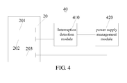
- the mobile terminal 40 comprises an interruption detection module 410, a power supply management module 420 and an SIM card connector 20 according to the aforesaid embodiment.
- the mobile terminal 40 is an electronic device such as a mobile phone, a tablet computer or a personal digital assistant (PDA).
- PDA personal digital assistant
- the power supply management module 420 is configured to, when the SIM card 21 is plugged in a powered-on state of the mobile terminal 40, supply power to the power supply terminal 203 so that the SIM card connector 20 communicates with the SIM card 21.
- the interruption detection module 410 is configured to detect whether levels at the first terminal 201 and the second terminal 202 are a predetermined level. If it is detected that neither of the levels is the predetermined level, then the interruption detection module 410 transmits a first control signal to the power supply management module 420, and otherwise, transmits a second control signal to the power supply management module 420.
- the levels at the first terminal 201 and the second terminal 202 are the predetermined level only when they connect to the power supply contact 211.
- the power supply management module 420 is further configured to supply power to the power supply terminal 203 when it is detected that a signal received changes from the first control signal into the second control signal; and stop supplying power to the power supply terminal 203 when it is detected that the signal received changes from the second control signal into the first control signal so as to prevent short-circuit of the SIM card 21 when the SIM card 21 is removed in a powered-on state of the mobile terminal 40.
- the predetermined level is a high level
- the first control signal is a low level
- the second control signal is the high level
- the interruption detection module 410 is an AND gate circuit.
- the two input terminals of the AND gate circuit are the first terminal 201 and the second terminal 202, and an output terminal of the AND gate circuit is connected to the power supply management module 420.
- both the first terminal 201 and the second terminal 202 are at a low level.
- the power supply management module 420 may supply power to the power supply terminal 203 as a default setting, and of course, it may also not supply power to the power supply terminal 203.
- the first terminal 201 connects to the power supply contact 211 but the second terminal 202 has not connected to the power supply contact 211 yet, the first terminal 201 is at a high level and the second terminal 202 is at a low level.
- the AND gate circuit outputs a low level, and the power supply management module 420 still keeps supplying power to the power supply terminal 203.
- both the first terminal 201 and the second terminal 202 connect to the power supply contact 211 (equivalent to a connection with the power supply terminal 203), and both the first terminal 201 and the second terminal 202 are at a high level.
- the AND gate circuit outputs a high level.
- the power supply management module 420 detects that a signal received changes from the low level into the high level, so it still keeps supplying power to the power supply terminal 203.
- the first terminal 201 is at a high level and the second terminal 202 is at a low level.
- the AND gate circuit outputs a low level.
- the power supply management module 420 detects that the signal received changes from the high level into the low level, so it stops supplying power to the power supply terminal 203.
- both the first terminal 201 and the second terminal 202 are disconnected from the power supply contacts 211 and are both at a low level.
- the AND gate circuit outputs a low level, and correspondingly, the power supply management module 420 does not supply power to the power supply terminal 203 yet.
- the power supply terminal 203 loses the power input immediately at the instant that the SIM card 21 is removed. In this way, short-circuit of the SIM card 21 when the SIM card 21 is removed in a powered-on state of the mobile terminal 40 can be prevented.
- the power supply contact 211 connects to the power supply terminal 203 of the SIM card connector 20 the latest among the conductive contacts of the SIM card 21. That is to way, even if the power supply terminal 203 connects to two conductive contacts simultaneously in the process of plugging the SIM card 21, there is still no power input to the SIM card 21 because the power supply contact 211 does not connect to the power supply terminal 203 and, thus, the SIM card 21 will not be short-circuited.
- the predetermined level is a high level
- the first control signal is the high level
- the second control signal is a low level
- the interruption detection module is an NAND gate circuit.
- the specific operation process of the mobile terminal 40 is similar to the aforesaid process, so it will not be further detailed herein.
- the SIM card connector and the mobile terminal of the present disclosure are provided with a first terminal, a second terminal and a power supply terminal in the SIM card connector, which are all connected to the power supply contact of the SIM card.
- the power supply terminal, the first terminal and the second terminal connect to the power supply contact sequentially.
- the interruption detection module transmits the first control signal to the power supply management module, and otherwise, transmits the second control signal to the power supply management module.
- the power supply module stops supplying power to the power supply terminal, and the levels at the first terminal and the second terminal are the predetermined level only when they connect to the power supply contact.
Landscapes
- Engineering & Computer Science (AREA)
- Signal Processing (AREA)
- Computer Networks & Wireless Communication (AREA)
- Artificial Intelligence (AREA)
- Computer Vision & Pattern Recognition (AREA)
- Physics & Mathematics (AREA)
- General Physics & Mathematics (AREA)
- Theoretical Computer Science (AREA)
- Microelectronics & Electronic Packaging (AREA)
- Telephone Function (AREA)
- Coupling Device And Connection With Printed Circuit (AREA)
- Telephone Set Structure (AREA)
Abstract
Description
- The present disclosure generally relates to the technical field of circuit designing, and more particularly, to an SIM card connector and also a mobile terminal.
- An SIM (Subscriber Identity Module) card stores information of a user of the corresponding digital mobile terminal, a key for encryption, a telephone book of the user and so on. The mobile terminal can be used by the user for communication only when the SIM card is plugged therein.
- The SIM card is provided with metal contacts, which connect with terminals of an SIM card connector of the mobile terminal to allow for communication. When the SIM card is completely plugged into the SIM card connector, each of the metal contacts connects to just one terminal. However, in the process of plugging the SIM card into or removing the SIM card from the SIM card connector, it is likely that some terminals of the SIM card connector connect to more than one metal contact simultaneously. If, in this case, the SIM card connector is still kept energized, there will be a risk of damaging the SIM card due to a short-circuit. For example, refer to
FIG. 1 , which is a schematic view illustrating operations of plugging or removing the SIM card in the prior art. After theSIM card 10 is completely plugged into the SIM card connector (not shown), themetal contacts 101 of theSIM card 10 are in one-to-one correspondence with theterminals 102 of the SIM card connector. In the process of removing theSIM card 10, it is likely that oneterminal 102 connects to twometal contacts 101 simultaneously because of the large touch areas between theterminal 102 and themetal contacts 101. If, in this case, theterminal 102 is still connected with the power supply, then theSIM card 10 will be short-circuited. - In mobile terminals of the early stage, the structure design is such that the battery can be installed only after the SIM card has been plugged and, on the other hand, the SIM card can be removed only after the battery has been removed, so there is no risk of short-circuit of the SIM card. However, as the mobile terminals are developing towards an integrated form, built-in batteries have become a general trend. Correspondingly, there might be cases where the SIM card is hot plugged in or removed with the mobile terminal being powered on.
- A primary objective of the present disclosure is to provide an SIM card connector and a mobile terminal which can support hot plug-in and removal of an SIM card.
- To solve the aforesaid technical problem, a solution adopted by the present disclosure is as follows: a mobile terminal, which comprises an AND gate circuit, a power supply management module and an SIM card connector for connecting an SIM card, wherein: the SIM card connector comprises a card holder as well as a power supply terminal, a first terminal and a second terminal disposed within the card holder, the SIM card is plugged into or removed from the card holder along a fixed direction, the second terminal is spaced apart from the first terminal by a first predetermined distance of 0.3mm along the fixed direction, and the first terminal is spaced apart from the power supply terminal by a second predetermined distance along the fixed direction; wherein the power supply terminal, the first terminal and the second terminal are all used to connect with a power supply contact of the SIM card, and when the SIM card is plugged, the power supply terminal connects with the power supply contact earlier than the first terminal, and the first terminal connects with the power supply contact earlier than the second terminal; and when the SIM card is removed, the second terminal is disconnected from the power supply contact earlier than the first terminal; the power supply management module is configured to, when the SIM card is plugged in a powered-on state of the mobile terminal, supply power to the power supply terminal so that the SIM card connector communicates with the SIM card; the AND gate circuit is configured to detect whether levels at the first terminal and the second terminal are a predetermined level, and if it is detected that neither of the levels is the predetermined level, then transmit a low level to the power supply management module, and otherwise, transmit a high level to the power supply management module, wherein the levels at the first terminal and the second terminal are the predetermined level only when they connect to the power supply contact; and the power supply management module is further configured to supply power to the power supply terminal when it is detected that a signal received changes from the low level into the high level; and stop supplying power to the power supply terminal when it is detected that the signal received changes from the high level into the low level so as to prevent short-circuit of the SIM card when the SIM card is removed in a powered-on state of the mobile terminal.
- To solve the aforesaid technical problem, another solution adopted by the present disclosure is as follows: an SIM card connector for connecting an SIM card, wherein the SIM card connector comprises a card holder as well as a power supply terminal, a first terminal and a second terminal disposed within the card holder, the SIM card is plugged into or removed from the card holder along a fixed direction, the second terminal is spaced apart from the first terminal by a first predetermined distance along the fixed direction, and the first terminal is spaced apart from the power supply terminal by a second predetermined distance along the fixed direction; and wherein the power supply terminal, the first terminal and the second terminal are all used to connect with a power supply contact of the SIM card, and when the SIM card is plugged, the power supply terminal connects with the power supply contact earlier than the first terminal, and the first terminal connects with the power supply contact earlier than the second terminal; and when the SIM card is removed, the second terminal is disconnected from the power supply contact earlier than the first terminal.
- The first predetermined distance is smaller than 1mm.
- The first predetermined distance is 0.3mm.
- To solve the aforesaid technical problem, yet another solution adopted by the present disclosure is as follows: a mobile terminal, which comprises an interruption detection module, a power supply management module and any of the aforesaid SIM card connectors, wherein the power supply management module is configured to, when the SIM card is plugged in a powered-on state of the mobile terminal, supply power to the power supply terminal so that the SIM card connector communicates with the SIM card; the interruption detection module is configured to detect whether levels at the first terminal and the second terminal are a predetermined level, and if it is detected that neither of the levels is the predetermined level, then transmit a first control signal to the power supply management module, and otherwise, transmit a second control signal to the power supply management module, wherein the levels at the first terminal and the second terminal are the predetermined level only when they connect to the power supply contact; and the power supply management module is further configured to supply power to the power supply terminal when it is detected that a signal received changes from the first control signal into the second control signal, and stop supplying power to the power supply terminal when it is detected that the signal received changes from the second control signal into the first control signal so as to prevent short-circuit of the SIM card when the SIM card is removed in a powered-on state of the mobile terminal.
- The predetermined level is a high level, the first control signal is a low level, the second control signal is the high level, and the interruption detection module is an AND gate circuit.
- The predetermined level is a high level, the first control signal is the high level, the second control signal is a low level, and the interruption detection module is an NAND gate circuit.
- The first predetermined distance is smaller than 1mm.
- The first predetermined distance is 0.3mm.
- The present disclosure has the following benefits: as compared to the prior art, the SIM card connector and the mobile terminal of the present disclosure are provided with a first terminal, a second terminal and a power supply terminal in the SIM card connector, which are all connected to the power supply contact of the SIM card; when the SIM card is plugged, the power supply terminal, the first terminal and the second terminal connect to the power supply contact sequentially; when it is detected that neither of the levels at the first terminal and the second terminal is a predetermined level, the interruption detection module transmits the first control signal to the power supply management module, and otherwise, transmits the second control signal to the power supply management module; and if it is detected that a signal received changes from the second control signal into the first control signal, the power supply module stops supplying power to the power supply terminal, and the levels at the first terminal and the second terminal are the predetermined level only when they connect to the power supply contact. Thereby, the goal of cutting off the power supply when the SIM card is removed can be achieved, thus solving the technical problem that the prior art cannot support hot plug-in and removal of the SIM card and preventing short-circuit of the SIM card when the SIM card is removed in a powered-on state of the mobile terminal.
-
-
FIG. 1 is a schematic view illustrating operations of plugging and removing an SIM card in the prior art; -
FIG. 2 is a schematic structural view of an embodiment of an SIM card connector according to the present disclosure; -
FIG. 3 is a schematic view illustrating operations of plugging an SIM card into and removing the SIM card from the SIM card connector shown inFIG. 2 ; and -
FIG. 4 is a schematic structural view of an embodiment of a mobile terminal according to the present disclosure. - Hereinbelow, technical solutions of embodiments of the present disclosure will be described clearly and completely with reference to the attached drawings. Obviously, embodiments described herein are only some of but not all of the embodiments of the present disclosure. All other embodiments that can be obtained without making inventive efforts by those of ordinary skill in the art upon reviewing the disclosures of the embodiments of the present disclosure shall fall within the scope of the present disclosure.
- Referring to
FIG. 2 , there is shown a schematic structural view of an embodiment of an SIM card connector according to the present disclosure. This figure shows not only a partially enlarged structure of acard holder 200 but also anSIM card 21. The SIM card is shown by dashed lines in order to clearly show the structure of thecard holder 200. - The
SIM card connector 20 comprises thecard holder 200 as well as afirst terminal 201, asecond terminal 202 and apower supply terminal 203 disposed within thecard holder 200. Thefirst terminal 201, thesecond terminal 202 and thepower supply terminal 203 are all used to connect with apower supply contact 211 of theSIM card 21. Generally speaking, a plurality of conductive terminals are disposed within thecard holder 200 in one-to-one correspondence with a plurality of conductive contacts on theSIM card 21, and thefirst terminal 201, thesecond terminal 202 and thepower supply terminals 203 are just a part of these conductive terminals. Similarly, thepower supply contact 211 of theSIM card 21 is one of the conductive contacts and acts as a power supply input terminal of theSIM card 21. TheSIM card 21 can operate when there is a power supply input at thepower supply contact 211. - The
SIM card 21 is plugged into or removed from thecard holder 200 along a fixed direction D, thesecond terminal 202 is spaced apart from thefirst terminal 201 by a first predetermined distance L1 along the fixed direction, and thefirst terminal 201 is spaced apart from thepower supply terminal 203 by a second predetermined distance L2 along the fixed direction. In this embodiment, the first predetermined distance L1 is less than 1mm, and preferably is 0.3mm. - Referring to
FIG. 3 , there is shown a schematic view illustrating operations of plugging an SIM card into and removing the SIM card from the SIM card connector shown inFIG. 2 . As can be seen, in the process of plugging theSIM card 21, thepower supply terminal 203 connects with thepower supply contact 211 earlier than thefirst terminal 201, and thefirst terminal 201 connects with thepower supply contact 211 earlier than thesecond terminal 202; and conversely, in the process of removing theSIM card 21, thesecond terminal 202 is disconnected from thepower supply contact 211 earlier than thefirst terminal 201, and thefirst terminal 201 is disconnected from thepower supply contact 211 earlier than thepower supply terminal 203. - Referring to
FIG. 4 , there is shown a schematic structural view of an embodiment of the mobile terminal according to the present disclosure. Themobile terminal 40 comprises aninterruption detection module 410, a powersupply management module 420 and anSIM card connector 20 according to the aforesaid embodiment. In this embodiment, themobile terminal 40 is an electronic device such as a mobile phone, a tablet computer or a personal digital assistant (PDA). - The power
supply management module 420 is configured to, when theSIM card 21 is plugged in a powered-on state of themobile terminal 40, supply power to thepower supply terminal 203 so that theSIM card connector 20 communicates with theSIM card 21. - The
interruption detection module 410 is configured to detect whether levels at thefirst terminal 201 and thesecond terminal 202 are a predetermined level. If it is detected that neither of the levels is the predetermined level, then theinterruption detection module 410 transmits a first control signal to the powersupply management module 420, and otherwise, transmits a second control signal to the powersupply management module 420. The levels at thefirst terminal 201 and thesecond terminal 202 are the predetermined level only when they connect to thepower supply contact 211. - The power
supply management module 420 is further configured to supply power to thepower supply terminal 203 when it is detected that a signal received changes from the first control signal into the second control signal; and stop supplying power to thepower supply terminal 203 when it is detected that the signal received changes from the second control signal into the first control signal so as to prevent short-circuit of theSIM card 21 when theSIM card 21 is removed in a powered-on state of themobile terminal 40. - In this embodiment, the predetermined level is a high level, the first control signal is a low level, the second control signal is the high level, and the
interruption detection module 410 is an AND gate circuit. The two input terminals of the AND gate circuit are thefirst terminal 201 and thesecond terminal 202, and an output terminal of the AND gate circuit is connected to the powersupply management module 420. - Hereinbelow, a specific operation process of the
mobile terminal 40 in the process of hot plug-in and removal of theSIM card 21 will be detailed. - When the
mobile terminal 40 is powered on but theSIM card 21 has not been plugged in, both thefirst terminal 201 and thesecond terminal 202 are at a low level. However, because themobile terminal 40 has just been powered on, the powersupply management module 420 may supply power to thepower supply terminal 203 as a default setting, and of course, it may also not supply power to thepower supply terminal 203. - In the process of plugging the
SIM card 21, when thefirst terminal 201 connects to thepower supply contact 211 but thesecond terminal 202 has not connected to thepower supply contact 211 yet, thefirst terminal 201 is at a high level and thesecond terminal 202 is at a low level. In this case, the AND gate circuit outputs a low level, and the powersupply management module 420 still keeps supplying power to thepower supply terminal 203. - After the
SIM card 21 has been completely plugged, both thefirst terminal 201 and thesecond terminal 202 connect to the power supply contact 211 (equivalent to a connection with the power supply terminal 203), and both thefirst terminal 201 and thesecond terminal 202 are at a high level. In this case, the AND gate circuit outputs a high level. Correspondingly, the powersupply management module 420 detects that a signal received changes from the low level into the high level, so it still keeps supplying power to thepower supply terminal 203. - In the process of removing the
SIM card 21, when thesecond terminal 202 is disconnected from thepower supply contact 211 but thefirst terminal 201 is still connected to thepower supply contact 211, thefirst terminal 201 is at a high level and thesecond terminal 202 is at a low level. In this case, the AND gate circuit outputs a low level. Correspondingly, the powersupply management module 420 detects that the signal received changes from the high level into the low level, so it stops supplying power to thepower supply terminal 203. - After the
SIM card 21 has been completely removed, both thefirst terminal 201 and thesecond terminal 202 are disconnected from thepower supply contacts 211 and are both at a low level. In this case, the AND gate circuit outputs a low level, and correspondingly, the powersupply management module 420 does not supply power to thepower supply terminal 203 yet. - Because the first predetermined distance L1 is very small, the
power supply terminal 203 loses the power input immediately at the instant that theSIM card 21 is removed. In this way, short-circuit of theSIM card 21 when theSIM card 21 is removed in a powered-on state of themobile terminal 40 can be prevented. - It shall be noted that, when the
mobile terminal 40 is initially powered on, short-circuit of theSIM card 21 will not be caused when theSIM card 21 is plugged regardless of whether the powersupply management module 420 supplies power to thepower supply terminal 203. According to the standard structure design of theSIM card 21, thepower supply contact 211 connects to thepower supply terminal 203 of theSIM card connector 20 the latest among the conductive contacts of theSIM card 21. That is to way, even if thepower supply terminal 203 connects to two conductive contacts simultaneously in the process of plugging theSIM card 21, there is still no power input to theSIM card 21 because thepower supply contact 211 does not connect to thepower supply terminal 203 and, thus, theSIM card 21 will not be short-circuited. - Further, in other embodiments, the predetermined level is a high level, the first control signal is the high level, the second control signal is a low level, and the interruption detection module is an NAND gate circuit. In this case, the specific operation process of the
mobile terminal 40 is similar to the aforesaid process, so it will not be further detailed herein. - According to the above descriptions, the SIM card connector and the mobile terminal of the present disclosure are provided with a first terminal, a second terminal and a power supply terminal in the SIM card connector, which are all connected to the power supply contact of the SIM card. When the SIM card is plugged, the power supply terminal, the first terminal and the second terminal connect to the power supply contact sequentially. When it is detected that neither of the levels at the first terminal and the second terminal is a predetermined level, the interruption detection module transmits the first control signal to the power supply management module, and otherwise, transmits the second control signal to the power supply management module. If it is detected that a signal received changes from the second control signal into the first control signal, the power supply module stops supplying power to the power supply terminal, and the levels at the first terminal and the second terminal are the predetermined level only when they connect to the power supply contact. Thereby, the goal of cutting off the power supply when the SIM card is removed can be achieved, thus solving the technical problem that the prior art cannot support hot plug-in and removal of the SIM card and preventing short-circuit of the SIM card when the SIM card is removed in a powered-on state of the mobile terminal.
- What described above are only the embodiments of the present disclosure, but are not intended to limit the scope of the present disclosure. Any equivalent structures or equivalent process flow modifications that are made according to the specification and the attached drawings of the present disclosure, or any direct or indirect applications of the present disclosure in other related technical fields shall all be covered within the scope of the present disclosure.
Claims (9)
- A mobile terminal, comprising an AND gate circuit, a power supply management module and an SIM card connector for connecting an SIM card, wherein:the SIM card connector comprises a card holder as well as a power supply terminal, a first terminal and a second terminal disposed within the card holder, the SIM card is plugged into or removed from the card holder along a fixed direction, the second terminal is spaced apart from the first terminal by a first predetermined distance of 0.3mm along the fixed direction, and the first terminal is spaced apart from the power supply terminal by a second predetermined distance along the fixed direction; wherein the power supply terminal, the first terminal and the second terminal are all used to connect with a power supply contact of the SIM card, and when the SIM card is plugged, the power supply terminal connects with the power supply contact earlier than the first terminal, and the first terminal connects with the power supply contact earlier than the second terminal; and when the SIM card is removed, the second terminal is disconnected from the power supply contact earlier than the first terminal;the power supply management module is configured to, when the SIM card is plugged in a powered-on state of the mobile terminal, supply power to the power supply terminal so that the SIM card connector communicates with the SIM card;the AND gate circuit is configured to detect whether levels at the first terminal and the second terminal are a predetermined level, and if it is detected that neither of the levels is the predetermined level, then transmit a low level to the power supply management module, and otherwise, transmit a high level to the power supply management module, wherein the levels at the first terminal and the second terminal are the predetermined level only when they connect to the power supply contact; andthe power supply management module is further configured to supply power to the power supply terminal when it is detected that a signal received changes from the low level into the high level; and stop supplying power to the power supply terminal when it is detected that the signal received changes from the high level into the low level so as to prevent short-circuit of the SIM card when the SIM card is removed in a powered-on state of the mobile terminal.
- An SIM card connector for connecting an SIM card, wherein the SIM card connector comprises a card holder as well as a power supply terminal, a first terminal and a second terminal disposed within the card holder, the SIM card is plugged into or removed from the card holder along a fixed direction, the second terminal is spaced apart from the first terminal by a first predetermined distance along the fixed direction, and the first terminal is spaced apart from the power supply terminal by a second predetermined distance along the fixed direction;
and wherein the power supply terminal, the first terminal and the second terminal are all used to connect with power supply contact of the SIM card, and when the SIM card is plugged, the power supply terminal connects with the power supply contact earlier than the first terminal, and the first terminal connects with the power supply contact earlier than the second terminal; and when the SIM card is removed, the second terminal is disconnected from the power supply contact earlier than the first terminal. - The SIM card connector of claim 2, wherein the first predetermined distance is smaller than 1mm.
- The SIM card connector of claim 3, wherein the first predetermined distance is 0.3mm.
- A mobile terminal, comprising an interruption detection module, a power supply management module and an SIM card connector for connecting an SIM card, wherein:the SIM card connector comprises a card holder as well as a power supply terminal, a first terminal and a second terminal disposed within the card holder, the SIM card is plugged into or removed from the card holder along a fixed direction, the second terminal is spaced apart from the first terminal by a first predetermined distance of 0.3mm along the fixed direction, and the first terminal is spaced apart from the power supply terminal by a second predetermined distance along the fixed direction; wherein the power supply terminal, the first terminal and the second terminal are all used to connect with a power supply contact of the SIM card, and when the SIM card is plugged, the power supply terminal connects with the power supply contact earlier than the first terminal, and the first terminal connects with the power supply contact earlier than the second terminal; and when the SIM card is removed, the second terminal is disconnected from the power supply contact earlier than the first terminal;the power supply management module is configured to, when the SIM card is plugged in a powered-on state of the mobile terminal, supply power to the power supply terminal so that the SIM card connector communicates with the SIM card;the interruption detection module is configured to detect whether levels at the first terminal and the second terminal are a predetermined level, and if it is detected that neither of the levels is the predetermined level, then transmit a first control signal to the power supply management module, and otherwise, transmit a second control signal to the power supply management module, wherein the levels at the first terminal and the second terminal are the predetermined level only when they connect to the power supply contact; andthe power supply management module is further configured to supply power to the power supply terminal when it is detected that a signal received changes from the first control signal into the second control signal; and stop supplying power to the power supply terminal when it is detected that the signal received changes from the second control signal into the first control signal so as to prevent short-circuit of the SIM card when the SIM card is removed in a powered-on state of the mobile terminal.
- The mobile terminal of claim 5, wherein the predetermined level is a high level, the first control signal is a low level, the second control signal is the high level, and the interruption detection module is an AND gate circuit.
- The mobile terminal of claim 5, wherein the predetermined level is a high level, the first control signal is the high level, the second control signal is a low level, and the interruption detection module is an NAND gate circuit.
- The mobile terminal of claim 5, wherein the first predetermined distance is smaller than 1mm.
- The mobile terminal of claim 5, wherein the first predetermined distance is 0.3mm.
Applications Claiming Priority (2)
| Application Number | Priority Date | Filing Date | Title |
|---|---|---|---|
| CN201310191088.5A CN103326149B (en) | 2013-05-21 | 2013-05-21 | Sim card connector and mobile terminal |
| PCT/CN2013/080836 WO2014187030A1 (en) | 2013-05-21 | 2013-08-05 | Sim card connector and mobile terminal |
Publications (3)
| Publication Number | Publication Date |
|---|---|
| EP2843768A1 true EP2843768A1 (en) | 2015-03-04 |
| EP2843768A4 EP2843768A4 (en) | 2016-01-06 |
| EP2843768B1 EP2843768B1 (en) | 2018-05-02 |
Family
ID=49194763
Family Applications (1)
| Application Number | Title | Priority Date | Filing Date |
|---|---|---|---|
| EP13884947.6A Active EP2843768B1 (en) | 2013-05-21 | 2013-08-05 | Sim card connector and mobile terminal |
Country Status (5)
| Country | Link |
|---|---|
| US (1) | US9258024B2 (en) |
| EP (1) | EP2843768B1 (en) |
| CN (1) | CN103326149B (en) |
| ES (1) | ES2669514T3 (en) |
| WO (1) | WO2014187030A1 (en) |
Families Citing this family (15)
| Publication number | Priority date | Publication date | Assignee | Title |
|---|---|---|---|---|
| CN103809879B (en) * | 2014-02-20 | 2017-01-18 | 联想(北京)有限公司 | Information processing method and electronic equipment |
| CN105100303A (en) * | 2014-05-22 | 2015-11-25 | 中兴通讯股份有限公司 | Power supply protecting device and terminal equipment |
| JP1553611S (en) * | 2015-11-03 | 2016-07-11 | ||
| JP1552812S (en) * | 2015-11-03 | 2016-06-27 | ||
| JP1553879S (en) * | 2015-11-03 | 2016-07-11 | ||
| JP1552814S (en) * | 2015-11-04 | 2016-06-27 | ||
| JP1552813S (en) * | 2015-11-04 | 2016-06-27 | ||
| JP1552815S (en) * | 2015-11-06 | 2016-06-27 | ||
| US10821922B2 (en) * | 2016-07-18 | 2020-11-03 | Texas Instruments Incorporated | Power control system |
| CN106207074B (en) * | 2016-07-20 | 2019-03-08 | 北京小米移动软件有限公司 | Trays and Electronic Devices |
| CN106210198B (en) * | 2016-07-29 | 2019-03-05 | 维沃移动通信有限公司 | A smart card protection circuit, mobile terminal and smart card protection method |
| CN106527607B (en) * | 2016-10-12 | 2019-10-29 | Tcl移动通信科技(宁波)有限公司 | A kind of configuration method and system of mobile terminal pin |
| CN106851025A (en) * | 2017-01-03 | 2017-06-13 | 惠州Tcl移动通信有限公司 | A kind of switch discharge device and mobile terminal for preventing power supply short circuit |
| CN107317897A (en) * | 2017-07-05 | 2017-11-03 | 宇龙计算机通信科技(深圳)有限公司 | Terminal deck and terminal |
| CN118821828A (en) * | 2024-06-24 | 2024-10-22 | 厦门紫光展锐科技有限公司 | A power control method, device, equipment and storage medium |
Family Cites Families (14)
| Publication number | Priority date | Publication date | Assignee | Title |
|---|---|---|---|---|
| US5547385A (en) * | 1994-05-27 | 1996-08-20 | The Whitaker Corporation | Blind mating guides on backwards compatible connector |
| US5478253A (en) * | 1994-09-21 | 1995-12-26 | The Whitaker Corporation | Electrostatic discharge contacts for blind mating connectors |
| RU2150745C1 (en) * | 1995-03-22 | 2000-06-10 | Фраматом Коннектор Энтернасьональ | Device for reading card with embedded chip |
| JP3020020B2 (en) * | 1995-05-18 | 2000-03-15 | モレックス インコーポレーテッド | Card connector |
| US6587354B1 (en) * | 1998-09-18 | 2003-07-01 | Duane B. Kutsch | Telecommunication assembly |
| GB2346726B (en) * | 1999-02-12 | 2003-05-07 | Nokia Mobile Phones Ltd | Mechanism for holding an intergrated circuit card |
| US7540766B2 (en) * | 2006-06-14 | 2009-06-02 | Itron, Inc. | Printed circuit board connector for utility meters |
| US7611386B1 (en) * | 2008-06-12 | 2009-11-03 | Hon Hai Precision Ind. Co., Ltd | Electrical connector with power contacts designed to handle instantaneous inrush current |
| CN101777709B (en) * | 2009-01-08 | 2012-05-30 | 倚天资讯股份有限公司 | Chip card connector |
| JP2012256530A (en) * | 2011-06-09 | 2012-12-27 | Tyco Electronics Japan Kk | Card connector |
| CN102548206B (en) * | 2012-02-20 | 2014-07-09 | 华为技术有限公司 | Golden finger, terminal and communication equipment mainboard |
| CN102665302B (en) * | 2012-04-01 | 2016-08-03 | 惠州Tcl移动通信有限公司 | A kind of wireless communication system |
| CN102945189B (en) * | 2012-11-07 | 2015-11-25 | 惠州Tcl移动通信有限公司 | Mobile terminal and storage card hot-plug method thereof |
| CN103001075B (en) * | 2012-12-12 | 2016-01-27 | 惠州Tcl移动通信有限公司 | A kind of mobile terminal and sim card connector thereof |
-
2013
- 2013-05-21 CN CN201310191088.5A patent/CN103326149B/en active Active
- 2013-08-05 EP EP13884947.6A patent/EP2843768B1/en active Active
- 2013-08-05 US US14/433,922 patent/US9258024B2/en active Active
- 2013-08-05 WO PCT/CN2013/080836 patent/WO2014187030A1/en not_active Ceased
- 2013-08-05 ES ES13884947.6T patent/ES2669514T3/en active Active
Also Published As
| Publication number | Publication date |
|---|---|
| US9258024B2 (en) | 2016-02-09 |
| ES2669514T3 (en) | 2018-05-28 |
| CN103326149A (en) | 2013-09-25 |
| WO2014187030A1 (en) | 2014-11-27 |
| CN103326149B (en) | 2016-06-08 |
| US20150280766A1 (en) | 2015-10-01 |
| EP2843768B1 (en) | 2018-05-02 |
| EP2843768A4 (en) | 2016-01-06 |
Similar Documents
| Publication | Publication Date | Title |
|---|---|---|
| US9258024B2 (en) | SIM card connector and mobile terminal | |
| US9197000B2 (en) | SIM card holder, mobile terminal and method for identifying hotplug of SIM card | |
| US9141141B2 (en) | Portable device and peripheral extension dock | |
| US20130335010A1 (en) | Connector and control chip | |
| CN104063348A (en) | Device and method for realizing compatible USB (Universal Serial Bus) communication and audio communication | |
| WO2015184833A1 (en) | Portable power source apparatus and charging/discharging processing method | |
| CN103094793A (en) | Smart card connecting circuit for electronic equipment and electronic equipment | |
| EP4160861A1 (en) | Charger, data cable, and charging device | |
| CN105048199B (en) | A kind of detecting system and its detection method of connector break-make | |
| KR20090084488A (en) | Method and apparatus for determining external device connected to mobile terminal | |
| CN106164686B (en) | A Terminal Leakage Current Detection System | |
| US8320963B2 (en) | Subscriber identity module card and terminal device having the same | |
| CN106526403A (en) | Terminal leak current detection circuit, terminal and terminal leak current detection system | |
| WO2016141572A1 (en) | Leakage current detection circuit of terminal, and terminal | |
| US8463978B2 (en) | Computer with ability to charge electronic device in power off state and USB interface module thereof | |
| CN106210198B (en) | A smart card protection circuit, mobile terminal and smart card protection method | |
| US8780514B2 (en) | Data cable and electronic device using same | |
| US20150253828A1 (en) | Electronic system | |
| EP3291404A1 (en) | Method and device for implementing connection control | |
| US12009680B2 (en) | Charging circuit, charging method, and terminal | |
| CN106786978A (en) | A kind of charging system and mobile terminal | |
| CN105071488B (en) | A kind of charging method and device of the terminal with data exchanging function | |
| JP2015106537A (en) | Power supply cable, relay connector, and electronic equipment unit | |
| CN105098854A (en) | Charging method and electronic device | |
| CN105224484B (en) | The method and apparatus that multiplex roles application is realized in ID authentication device |
Legal Events
| Date | Code | Title | Description |
|---|---|---|---|
| PUAI | Public reference made under article 153(3) epc to a published international application that has entered the european phase |
Free format text: ORIGINAL CODE: 0009012 |
|
| 17P | Request for examination filed |
Effective date: 20141125 |
|
| AK | Designated contracting states |
Kind code of ref document: A1 Designated state(s): AL AT BE BG CH CY CZ DE DK EE ES FI FR GB GR HR HU IE IS IT LI LT LU LV MC MK MT NL NO PL PT RO RS SE SI SK SM TR |
|
| AX | Request for extension of the european patent |
Extension state: BA ME |
|
| RA4 | Supplementary search report drawn up and despatched (corrected) |
Effective date: 20151203 |
|
| RIC1 | Information provided on ipc code assigned before grant |
Ipc: G06K 7/00 20060101ALI20151127BHEP Ipc: H01R 13/66 20060101ALI20151127BHEP Ipc: H04B 1/3816 20150101ALI20151127BHEP Ipc: H04M 1/725 20060101ALI20151127BHEP Ipc: H01R 12/71 20110101AFI20151127BHEP |
|
| DAX | Request for extension of the european patent (deleted) | ||
| REG | Reference to a national code |
Ref country code: DE Ref legal event code: R079 Ref document number: 602013037103 Country of ref document: DE Free format text: PREVIOUS MAIN CLASS: H01R0012710000 Ipc: G06K0007000000 |
|
| GRAP | Despatch of communication of intention to grant a patent |
Free format text: ORIGINAL CODE: EPIDOSNIGR1 |
|
| RIC1 | Information provided on ipc code assigned before grant |
Ipc: H01R 12/71 20110101ALI20180115BHEP Ipc: H04M 1/274 20060101ALI20180115BHEP Ipc: H04B 1/3816 20150101ALI20180115BHEP Ipc: G06K 7/00 20060101AFI20180115BHEP Ipc: H04B 1/3818 20150101ALI20180115BHEP Ipc: H01R 13/66 20060101ALI20180115BHEP |
|
| INTG | Intention to grant announced |
Effective date: 20180207 |
|
| GRAS | Grant fee paid |
Free format text: ORIGINAL CODE: EPIDOSNIGR3 |
|
| GRAA | (expected) grant |
Free format text: ORIGINAL CODE: 0009210 |
|
| AK | Designated contracting states |
Kind code of ref document: B1 Designated state(s): AL AT BE BG CH CY CZ DE DK EE ES FI FR GB GR HR HU IE IS IT LI LT LU LV MC MK MT NL NO PL PT RO RS SE SI SK SM TR |
|
| REG | Reference to a national code |
Ref country code: GB Ref legal event code: FG4D |
|
| REG | Reference to a national code |
Ref country code: CH Ref legal event code: EP Ref country code: AT Ref legal event code: REF Ref document number: 996027 Country of ref document: AT Kind code of ref document: T Effective date: 20180515 |
|
| REG | Reference to a national code |
Ref country code: ES Ref legal event code: FG2A Ref document number: 2669514 Country of ref document: ES Kind code of ref document: T3 Effective date: 20180528 |
|
| REG | Reference to a national code |
Ref country code: DE Ref legal event code: R096 Ref document number: 602013037103 Country of ref document: DE Ref country code: IE Ref legal event code: FG4D |
|
| REG | Reference to a national code |
Ref country code: FR Ref legal event code: PLFP Year of fee payment: 6 |
|
| REG | Reference to a national code |
Ref country code: NL Ref legal event code: MP Effective date: 20180502 |
|
| REG | Reference to a national code |
Ref country code: LT Ref legal event code: MG4D |
|
| PG25 | Lapsed in a contracting state [announced via postgrant information from national office to epo] |
Ref country code: NO Free format text: LAPSE BECAUSE OF FAILURE TO SUBMIT A TRANSLATION OF THE DESCRIPTION OR TO PAY THE FEE WITHIN THE PRESCRIBED TIME-LIMIT Effective date: 20180802 Ref country code: FI Free format text: LAPSE BECAUSE OF FAILURE TO SUBMIT A TRANSLATION OF THE DESCRIPTION OR TO PAY THE FEE WITHIN THE PRESCRIBED TIME-LIMIT Effective date: 20180502 Ref country code: LT Free format text: LAPSE BECAUSE OF FAILURE TO SUBMIT A TRANSLATION OF THE DESCRIPTION OR TO PAY THE FEE WITHIN THE PRESCRIBED TIME-LIMIT Effective date: 20180502 Ref country code: SE Free format text: LAPSE BECAUSE OF FAILURE TO SUBMIT A TRANSLATION OF THE DESCRIPTION OR TO PAY THE FEE WITHIN THE PRESCRIBED TIME-LIMIT Effective date: 20180502 Ref country code: BG Free format text: LAPSE BECAUSE OF FAILURE TO SUBMIT A TRANSLATION OF THE DESCRIPTION OR TO PAY THE FEE WITHIN THE PRESCRIBED TIME-LIMIT Effective date: 20180802 |
|
| PG25 | Lapsed in a contracting state [announced via postgrant information from national office to epo] |
Ref country code: NL Free format text: LAPSE BECAUSE OF FAILURE TO SUBMIT A TRANSLATION OF THE DESCRIPTION OR TO PAY THE FEE WITHIN THE PRESCRIBED TIME-LIMIT Effective date: 20180502 Ref country code: LV Free format text: LAPSE BECAUSE OF FAILURE TO SUBMIT A TRANSLATION OF THE DESCRIPTION OR TO PAY THE FEE WITHIN THE PRESCRIBED TIME-LIMIT Effective date: 20180502 Ref country code: RS Free format text: LAPSE BECAUSE OF FAILURE TO SUBMIT A TRANSLATION OF THE DESCRIPTION OR TO PAY THE FEE WITHIN THE PRESCRIBED TIME-LIMIT Effective date: 20180502 Ref country code: GR Free format text: LAPSE BECAUSE OF FAILURE TO SUBMIT A TRANSLATION OF THE DESCRIPTION OR TO PAY THE FEE WITHIN THE PRESCRIBED TIME-LIMIT Effective date: 20180803 Ref country code: HR Free format text: LAPSE BECAUSE OF FAILURE TO SUBMIT A TRANSLATION OF THE DESCRIPTION OR TO PAY THE FEE WITHIN THE PRESCRIBED TIME-LIMIT Effective date: 20180502 |
|
| REG | Reference to a national code |
Ref country code: AT Ref legal event code: MK05 Ref document number: 996027 Country of ref document: AT Kind code of ref document: T Effective date: 20180502 |
|
| PG25 | Lapsed in a contracting state [announced via postgrant information from national office to epo] |
Ref country code: DK Free format text: LAPSE BECAUSE OF FAILURE TO SUBMIT A TRANSLATION OF THE DESCRIPTION OR TO PAY THE FEE WITHIN THE PRESCRIBED TIME-LIMIT Effective date: 20180502 Ref country code: AT Free format text: LAPSE BECAUSE OF FAILURE TO SUBMIT A TRANSLATION OF THE DESCRIPTION OR TO PAY THE FEE WITHIN THE PRESCRIBED TIME-LIMIT Effective date: 20180502 Ref country code: EE Free format text: LAPSE BECAUSE OF FAILURE TO SUBMIT A TRANSLATION OF THE DESCRIPTION OR TO PAY THE FEE WITHIN THE PRESCRIBED TIME-LIMIT Effective date: 20180502 Ref country code: PL Free format text: LAPSE BECAUSE OF FAILURE TO SUBMIT A TRANSLATION OF THE DESCRIPTION OR TO PAY THE FEE WITHIN THE PRESCRIBED TIME-LIMIT Effective date: 20180502 Ref country code: SK Free format text: LAPSE BECAUSE OF FAILURE TO SUBMIT A TRANSLATION OF THE DESCRIPTION OR TO PAY THE FEE WITHIN THE PRESCRIBED TIME-LIMIT Effective date: 20180502 Ref country code: RO Free format text: LAPSE BECAUSE OF FAILURE TO SUBMIT A TRANSLATION OF THE DESCRIPTION OR TO PAY THE FEE WITHIN THE PRESCRIBED TIME-LIMIT Effective date: 20180502 Ref country code: CZ Free format text: LAPSE BECAUSE OF FAILURE TO SUBMIT A TRANSLATION OF THE DESCRIPTION OR TO PAY THE FEE WITHIN THE PRESCRIBED TIME-LIMIT Effective date: 20180502 |
|
| REG | Reference to a national code |
Ref country code: DE Ref legal event code: R097 Ref document number: 602013037103 Country of ref document: DE |
|
| PG25 | Lapsed in a contracting state [announced via postgrant information from national office to epo] |
Ref country code: SM Free format text: LAPSE BECAUSE OF FAILURE TO SUBMIT A TRANSLATION OF THE DESCRIPTION OR TO PAY THE FEE WITHIN THE PRESCRIBED TIME-LIMIT Effective date: 20180502 |
|
| PLBE | No opposition filed within time limit |
Free format text: ORIGINAL CODE: 0009261 |
|
| STAA | Information on the status of an ep patent application or granted ep patent |
Free format text: STATUS: NO OPPOSITION FILED WITHIN TIME LIMIT |
|
| PG25 | Lapsed in a contracting state [announced via postgrant information from national office to epo] |
Ref country code: MC Free format text: LAPSE BECAUSE OF FAILURE TO SUBMIT A TRANSLATION OF THE DESCRIPTION OR TO PAY THE FEE WITHIN THE PRESCRIBED TIME-LIMIT Effective date: 20180502 |
|
| REG | Reference to a national code |
Ref country code: CH Ref legal event code: PL |
|
| 26N | No opposition filed |
Effective date: 20190205 |
|
| PG25 | Lapsed in a contracting state [announced via postgrant information from national office to epo] |
Ref country code: CH Free format text: LAPSE BECAUSE OF NON-PAYMENT OF DUE FEES Effective date: 20180831 Ref country code: LI Free format text: LAPSE BECAUSE OF NON-PAYMENT OF DUE FEES Effective date: 20180831 Ref country code: LU Free format text: LAPSE BECAUSE OF NON-PAYMENT OF DUE FEES Effective date: 20180805 |
|
| REG | Reference to a national code |
Ref country code: BE Ref legal event code: MM Effective date: 20180831 |
|
| REG | Reference to a national code |
Ref country code: IE Ref legal event code: MM4A |
|
| PG25 | Lapsed in a contracting state [announced via postgrant information from national office to epo] |
Ref country code: SI Free format text: LAPSE BECAUSE OF FAILURE TO SUBMIT A TRANSLATION OF THE DESCRIPTION OR TO PAY THE FEE WITHIN THE PRESCRIBED TIME-LIMIT Effective date: 20180502 |
|
| PG25 | Lapsed in a contracting state [announced via postgrant information from national office to epo] |
Ref country code: IE Free format text: LAPSE BECAUSE OF NON-PAYMENT OF DUE FEES Effective date: 20180805 |
|
| PG25 | Lapsed in a contracting state [announced via postgrant information from national office to epo] |
Ref country code: BE Free format text: LAPSE BECAUSE OF NON-PAYMENT OF DUE FEES Effective date: 20180831 |
|
| PG25 | Lapsed in a contracting state [announced via postgrant information from national office to epo] |
Ref country code: AL Free format text: LAPSE BECAUSE OF FAILURE TO SUBMIT A TRANSLATION OF THE DESCRIPTION OR TO PAY THE FEE WITHIN THE PRESCRIBED TIME-LIMIT Effective date: 20180502 |
|
| PG25 | Lapsed in a contracting state [announced via postgrant information from national office to epo] |
Ref country code: MT Free format text: LAPSE BECAUSE OF NON-PAYMENT OF DUE FEES Effective date: 20180805 |
|
| PG25 | Lapsed in a contracting state [announced via postgrant information from national office to epo] |
Ref country code: TR Free format text: LAPSE BECAUSE OF FAILURE TO SUBMIT A TRANSLATION OF THE DESCRIPTION OR TO PAY THE FEE WITHIN THE PRESCRIBED TIME-LIMIT Effective date: 20180502 |
|
| PG25 | Lapsed in a contracting state [announced via postgrant information from national office to epo] |
Ref country code: HU Free format text: LAPSE BECAUSE OF FAILURE TO SUBMIT A TRANSLATION OF THE DESCRIPTION OR TO PAY THE FEE WITHIN THE PRESCRIBED TIME-LIMIT; INVALID AB INITIO Effective date: 20130805 Ref country code: PT Free format text: LAPSE BECAUSE OF FAILURE TO SUBMIT A TRANSLATION OF THE DESCRIPTION OR TO PAY THE FEE WITHIN THE PRESCRIBED TIME-LIMIT Effective date: 20180502 |
|
| PG25 | Lapsed in a contracting state [announced via postgrant information from national office to epo] |
Ref country code: MK Free format text: LAPSE BECAUSE OF NON-PAYMENT OF DUE FEES Effective date: 20180502 Ref country code: CY Free format text: LAPSE BECAUSE OF FAILURE TO SUBMIT A TRANSLATION OF THE DESCRIPTION OR TO PAY THE FEE WITHIN THE PRESCRIBED TIME-LIMIT Effective date: 20180502 |
|
| PG25 | Lapsed in a contracting state [announced via postgrant information from national office to epo] |
Ref country code: IS Free format text: LAPSE BECAUSE OF FAILURE TO SUBMIT A TRANSLATION OF THE DESCRIPTION OR TO PAY THE FEE WITHIN THE PRESCRIBED TIME-LIMIT Effective date: 20180902 |
|
| P01 | Opt-out of the competence of the unified patent court (upc) registered |
Effective date: 20230530 |
|
| PGFP | Annual fee paid to national office [announced via postgrant information from national office to epo] |
Ref country code: ES Payment date: 20250926 Year of fee payment: 13 |
|
| PGFP | Annual fee paid to national office [announced via postgrant information from national office to epo] |
Ref country code: DE Payment date: 20250820 Year of fee payment: 13 |
|
| PGFP | Annual fee paid to national office [announced via postgrant information from national office to epo] |
Ref country code: IT Payment date: 20250825 Year of fee payment: 13 |
|
| PGFP | Annual fee paid to national office [announced via postgrant information from national office to epo] |
Ref country code: GB Payment date: 20250820 Year of fee payment: 13 |
|
| PGFP | Annual fee paid to national office [announced via postgrant information from national office to epo] |
Ref country code: FR Payment date: 20250829 Year of fee payment: 13 |