EP3291404A1 - Method and device for implementing connection control - Google Patents
Method and device for implementing connection control Download PDFInfo
- Publication number
- EP3291404A1 EP3291404A1 EP15890460.7A EP15890460A EP3291404A1 EP 3291404 A1 EP3291404 A1 EP 3291404A1 EP 15890460 A EP15890460 A EP 15890460A EP 3291404 A1 EP3291404 A1 EP 3291404A1
- Authority
- EP
- European Patent Office
- Prior art keywords
- data line
- state
- electric equipment
- connection
- wireless charging
- Prior art date
- Legal status (The legal status is an assumption and is not a legal conclusion. Google has not performed a legal analysis and makes no representation as to the accuracy of the status listed.)
- Withdrawn
Links
Images

Classifications
-
- H—ELECTRICITY
- H02—GENERATION; CONVERSION OR DISTRIBUTION OF ELECTRIC POWER
- H02J—CIRCUIT ARRANGEMENTS OR SYSTEMS FOR SUPPLYING OR DISTRIBUTING ELECTRIC POWER; SYSTEMS FOR STORING ELECTRIC ENERGY
- H02J7/00—Circuit arrangements for charging or depolarising batteries or for supplying loads from batteries
-
- G—PHYSICS
- G05—CONTROLLING; REGULATING
- G05B—CONTROL OR REGULATING SYSTEMS IN GENERAL; FUNCTIONAL ELEMENTS OF SUCH SYSTEMS; MONITORING OR TESTING ARRANGEMENTS FOR SUCH SYSTEMS OR ELEMENTS
- G05B19/00—Programme-control systems
- G05B19/02—Programme-control systems electric
- G05B19/04—Programme control other than numerical control, i.e. in sequence controllers or logic controllers
- G05B19/10—Programme control other than numerical control, i.e. in sequence controllers or logic controllers using selector switches
-
- G—PHYSICS
- G05—CONTROLLING; REGULATING
- G05B—CONTROL OR REGULATING SYSTEMS IN GENERAL; FUNCTIONAL ELEMENTS OF SUCH SYSTEMS; MONITORING OR TESTING ARRANGEMENTS FOR SUCH SYSTEMS OR ELEMENTS
- G05B2219/00—Program-control systems
- G05B2219/20—Pc systems
- G05B2219/26—Pc applications
- G05B2219/2639—Energy management, use maximum of cheap power, keep peak load low
-
- H—ELECTRICITY
- H02—GENERATION; CONVERSION OR DISTRIBUTION OF ELECTRIC POWER
- H02J—CIRCUIT ARRANGEMENTS OR SYSTEMS FOR SUPPLYING OR DISTRIBUTING ELECTRIC POWER; SYSTEMS FOR STORING ELECTRIC ENERGY
- H02J7/00—Circuit arrangements for charging or depolarising batteries or for supplying loads from batteries
- H02J7/00032—Circuit arrangements for charging or depolarising batteries or for supplying loads from batteries characterised by data exchange
- H02J7/00034—Charger exchanging data with an electronic device, i.e. telephone, whose internal battery is under charge
Definitions
- the present disclosure relates to electronic control technologies, and more particularly, to a method and device for implementing connection control.
- wireless charging stems from the wireless power transmission technologies, in which energy is transmitted by power supply equipment (chargers) to electric devices by means of inductive coupling to charge batteries. Energy transmission between the power supply equipment and the electric devices can be implemented through inductive coupling. Therefore, the power supply equipment and the electric devices may implement nonconductive contact point exposure without wired connection.
- power supply equipment chargers
- inductive coupling energy transmission between the power supply equipment and the electric devices can be implemented through inductive coupling. Therefore, the power supply equipment and the electric devices may implement nonconductive contact point exposure without wired connection.
- receivers of the electric devices are charged by converting AC signal to 5V DC signal.
- the output signal is only a power line and a ground wire.
- Charging managers of most of electric devices in the market regard by default, chargers only provided with power lines and ground wires as a computer connection entry USB mode. In this mode, charging current less than or equal to 500mA (such as 450mA) can be supplied.
- Counting system consumption in, current actually available for battery charging is only about 400mA, which leads to a slow charging process. Therefore, the above mode is slow in charging and unable to meet charging demands of users, which affects the application of the wireless charging technologies.
- the wireless charging is configured as AC charging since the charge manager has completed the enumeration of charge types.
- the wireless charging is interrupted, after the USB connection is disconnected or the OTG equipment is removed, it is impossible to recover the wireless charging because the wireless charging communication is disconnected. That is, because of cutoff of wireless charging, the charging manager performs enumeration of charge types. Therefore, it is still impossible to recognize disconnection of the USB connection or removal of the OTG equipment.
- the method of using two charging managers has a great impact on the electric devices in cost and PCB layout, which is to the disadvantage of application of the electric devices.
- the method of using one charging manager is adopted, it is impossible to recognize connection of a computer or OTG equipment after completing enumeration of wireless charging, and it is impossible to recognize disconnection of the USB connection or removal of the OTG equipment after completing enumeration of connection of the computer or OTG equipment. Therefore, the method of using one charging manager is also unavailable for wireless charging.
- Embodiments of the present disclosure provide a method and device for implementing connection control, which can recognize a connection state of an electric terminal, thereby correctly performing corresponding connection control.
- An embodiment of the present disclosure provides a method for implementing connection control, including:
- connection parameter information includes one or more of following parameters:
- the determining, according to the connection parameter information, a connection state of electric equipment includes:
- the controlling, according to the connection state of the electric equipment, ON or OFF of a circuit and/or an enabled state of the circuit includes:
- ON or OFF of the circuit is implemented by means of one or more analog switches.
- An embodiment of the present disclosure also provides a device for implementing connection control, which includes a determining unit and a switching unit.
- the determining unit is configured to read connection parameter information from a charging manager, and determine, according to the connection parameter information, a connection state of electric equipment.
- the switching unit is configured to control, according to the connection state of the electric equipment, ON or OFF of a circuit and/or an enabled state of the circuit.
- connection parameter information includes one or more of following parameters: a wireless charging state parameter CHG, a power line VBUS ON state, an external power input pin voltage value, and an ID detection parameter for determining whether there is an On-The-Go (OTG) equipment connection.
- a wireless charging state parameter CHG a wireless charging state parameter
- a power line VBUS ON state a power line VBUS ON state
- an external power input pin voltage value a wireless charging state parameter CHG
- ID detection parameter for determining whether there is an On-The-Go (OTG) equipment connection.
- the determining, by the determining unit according to the connection parameter information, a connection state of electric equipment includes:
- the switching unit is configured to:
- the switching unit is configured to implement OFF or ON of the circuit by means of one or more analog switches according to the connection state of the electric equipment, and/or implement the enabled state of the circuit by means of an enable signal so as to implement switching control of connection.
- the device further includes a baseband chip unit, configured to control the analog switches and/or transmit a wireless charging enable or disenable signal according to a signal of the switching unit.
- a baseband chip unit configured to control the analog switches and/or transmit a wireless charging enable or disenable signal according to a signal of the switching unit.
- An embodiment of the present disclosure further provides a computer readable storage medium, which stores program instructions. When the program instructions are executed, the above method may be implemented.
- the technical solution of the embodiment of the present disclosure includes: reading connection parameter information from a charging manager, and determining, according to the connection parameter information, a connection state of electric equipment; and controlling, according to the connection state of the electric equipment, ON or OFF of a circuit and/or an enabled state of the circuit.
- the connection state of the electric equipment is determined according to the connection parameter information, thereby implementing the connection control. In this way, connection management of the electric equipment merely applicable to one charging manager is implemented, thereby reducing cost and guaranteeing the switching control of wireless charging or connection of the electric equipment when the connection changes.
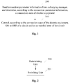
- FIG. 1 is a flowchart illustrating a method for implementing connection control according to an embodiment of the present disclosure. As shown in FIG. 1 , the method includes following steps.
- connection parameter information is read from a charging manager, and a connection state of electric equipment is determined according to the connection parameter information.
- connection parameter information includes one or more of following parameters:
- the determining, according to the connection parameter information, a connection state of electric equipment includes:
- Step 101 the switching control of connection is implemented by controlling, according to the connection state of the electric equipment, ON or OFF of a circuit and/or an enabled state of the circuit.
- a data line anode is disconnected from a data line cathode of the electric equipment, and connection between the data line anode and the data line cathode is turned on; or when the electric equipment is in the wired charging state, the connection of the data line anode and the data line cathode of the electric equipment is turned on, the data line anode is disconnected from the data line cathode, and a circuit controlling external power input is turned on; or when the electric equipment is in the USB-connecting computer state, the connection of the data line anode and the data line cathode of the electric equipment is turned on, the data line anode is disconnected from the data line cathode, and the circuit controlling external power input is turned on; or when the electric equipment is in the connection OTG equipment state, the connection of the data line anode and the data line cathode of the electric equipment is turned on, the data line anode is disconnected from the data line cathode, and the circuit controlling external power input is turned on; or when the electric equipment is in the
- ON or OFF of the circuit may be implemented by means of one or more analog switches.
- FIG. 2 is a block diagram illustrating a device for implementing connection control according to an embodiment of the present disclosure. As shown in FIG. 2 , the device includes a determining unit 200 and a switching unit 201.
- the determining unit 200 is configured to read connection parameter information from a charging manager, and determine, according to the connection parameter information, a connection state of electric equipment.
- the switching unit 201 is configured to control, according to the connection state of the electric equipment, ON or OFF of a circuit and/or an enabled state of the circuit.
- connection parameter information includes one or more of following parameters: a wireless charging state parameter CHG, a power line VBUS ON state, an external power input pin voltage value, and an ID detection parameter for determining whether there is an On-The-Go (OTG) equipment connection.
- a wireless charging state parameter CHG a wireless charging state parameter
- a power line VBUS ON state a power line VBUS ON state
- an external power input pin voltage value a wireless charging state parameter CHG
- ID detection parameter for determining whether there is an On-The-Go (OTG) equipment connection.
- the determining, by the determining unit 200 according to the connection parameter information, a connection state of electric equipment includes:
- the switching unit 201 is configured to:
- the switching unit 201 is configured to implement OFF or ON of the circuit by means of one or more analog switches according to the connection state of the electric equipment, and/or implement the enabled state of the circuit by means of an enable signal so as to implement switching control of connection.
- the device according to the embodiment of the present disclosure further includes a baseband chip unit, which is configured to control the analog switches and/or transmit a wireless charging enable or disenable signal according to a signal of the switching unit.
- FIG. 3 is a circuit connection diagram of electric equipment according to an application example.
- S1, S2, S3 and S4 represent analog switches, which are arranged in the circuit in the form of analog switch chips.
- a wireless charging output is connected to the analog switch S4.
- the S2 is configured to control ON or OFF of the data line anode of the electric equipment.
- the S1 is configured to control ON or OFF of the data line cathode of the electric equipment.
- the S3 is configured to control ON or OFF of a circuit between the data line anode and the data line cathode.
- the S4 is configured to control ON or OFF of a circuit of an external power input. Switches of the S1, S2, S3 and S4 are controlled by baseband signal.
- the wireless charging enable is controlled by an enable signal transmitted by the baseband chip.
- the connection parameter information read from a USB connector includes: a wireless charging state parameter CHG, a power line VBUS ON state, an external power input pin voltage value, and an ID detection parameter for determining whether there is an On-The-Go (OTG) equipment connection.
- the electric equipment is determined as a wireless charging state when the wireless charging state parameter CHG is a high level.
- the electric equipment is determined as a wired charging state when the power line VBUS ON state is ON and the external power input pin voltage value is greater than 3.6V.
- the electric equipment is determined as a USB-connecting computer state when the power line VBUS ON state is ON and the external power input pin voltage value is smaller than 3.6V.
- the electric equipment is determined as a connection OTG equipment state when the ID detection parameter determines there is OTG equipment.
- the electric equipment is determined as a USB-connecting computer and wireless charging disenabled state when the wireless charging state parameter CHG is a high level, the power line VBUS is ON and the external power input pin voltage value is smaller than 3.6V.
- the electric equipment is determined as a connection OTG equipment and wireless charging disenabled state when the wireless charging state parameter CHG is a high level and the ID detection parameter determines there is OTG equipment.
- the electric equipment is determined as an idle state when the wireless charging state parameter CHG is a low level, the power line VBUS is OFF and the ID detection parameter determines no OTG equipment is connected.
- the S1 and the S2 are turned off, the S3 is turned on, and the S4 is turned off.
- the S 1 and the S2 are turned on, the S3 is turned off, and the S4 is turned on.
- the S 1 and the S2 are turned on, the S3 is turned off, and the S4 is turned on.
- the S1 and the S2 are turned on, the S3 is turned off, a wireless charging disenabled signal is transmitted so that the wireless charging is disenabled, and the S4 is turned on.
- the S1 and the S2 are turned on, the S3 is turned off, the S4 is turned on, and a wireless charging disenabled signal is transmitted so that the wireless charging is disenabled.
- connection state of electric equipment is determined according to the connection parameter information, thereby implementing the connection control.
- connection management of the electric equipment merely applicable to one charging manager is implemented, thereby reducing cost and guaranteeing the switching control of wireless charging or connection of the electric equipment when the connection changes.
Abstract
Description
- The present disclosure relates to electronic control technologies, and more particularly, to a method and device for implementing connection control.
- As mobile terminal charging technologies are in the continuous development, charging needs become increasingly simple, fast and diversified. Consequently, wireless charging technologies are generated on demand. Also known as inductive charging, wireless charging stems from the wireless power transmission technologies, in which energy is transmitted by power supply equipment (chargers) to electric devices by means of inductive coupling to charge batteries. Energy transmission between the power supply equipment and the electric devices can be implemented through inductive coupling. Therefore, the power supply equipment and the electric devices may implement nonconductive contact point exposure without wired connection.
- During wireless charging, receivers of the electric devices are charged by converting AC signal to 5V DC signal. Unlike standard chargers (wired chargers), the output signal is only a power line and a ground wire. Charging managers of most of electric devices in the market regard, by default, chargers only provided with power lines and ground wires as a computer connection entry USB mode. In this mode, charging current less than or equal to 500mA (such as 450mA) can be supplied. Counting system consumption in, current actually available for battery charging is only about 400mA, which leads to a slow charging process. Therefore, the above mode is slow in charging and unable to meet charging demands of users, which affects the application of the wireless charging technologies.
- To improve the wireless charging efficiency, most of electric devices having wireless charging functions are provided with different charging managers for wired charging and wireless charging, which increases costs of the electric devices and layouts of printed circuit boards (PCBs). If one charging manager is used, the wireless charging is configured as AC charging since the charge manager has completed the enumeration of charge types. Thus, when a computer or OTG equipment is connected during wireless charging, it is impossible to recognize the computer or OTG equipment. If the wireless charging is interrupted, after the USB connection is disconnected or the OTG equipment is removed, it is impossible to recover the wireless charging because the wireless charging communication is disconnected. That is, because of cutoff of wireless charging, the charging manager performs enumeration of charge types. Therefore, it is still impossible to recognize disconnection of the USB connection or removal of the OTG equipment.
- In summary, the method of using two charging managers has a great impact on the electric devices in cost and PCB layout, which is to the disadvantage of application of the electric devices. However, if the method of using one charging manager is adopted, it is impossible to recognize connection of a computer or OTG equipment after completing enumeration of wireless charging, and it is impossible to recognize disconnection of the USB connection or removal of the OTG equipment after completing enumeration of connection of the computer or OTG equipment. Therefore, the method of using one charging manager is also unavailable for wireless charging.
- Embodiments of the present disclosure provide a method and device for implementing connection control, which can recognize a connection state of an electric terminal, thereby correctly performing corresponding connection control.
- An embodiment of the present disclosure provides a method for implementing connection control, including:
- reading connection parameter information from a charging manager, and determining, according to the connection parameter information, a connection state of electric equipment; and
- controlling, according to the connection state of the electric equipment, ON or OFF of a circuit and/or an enabled state of the circuit.
- Alternatively, the connection parameter information includes one or more of following parameters:
- a wireless charging state parameter CHG, a power line VBUS ON state, an external power input pin voltage value, and an identity number ID detection parameter for determining whether there is an On-The-Go (OTG) equipment connection.
- Alternatively, the determining, according to the connection parameter information, a connection state of electric equipment includes:
- determining the electric equipment as a wireless charging state when the wireless charging state parameter CHG is a high level; or
- determining the electric equipment as a wired charging state when the power line VBUS ON state is ON and the external power input pin voltage value is greater than a preset voltage value; or
- determining the electric equipment as a USB-connecting computer state when the power line VBUS ON state is ON and the external power input pin voltage value is smaller than the preset voltage value; or
- determining the electric equipment as a connection OTG equipment state when the ID detection parameter determines there is OTG equipment; or
- determining the electric equipment as a USB-connecting computer and wireless charging disenabled state when the wireless charging state parameter CHG is the high level, the power line VBUS ON state is ON and the external power input pin voltage value is smaller than the preset voltage value; or
- determining the electric equipment as a connection OTG equipment and wireless charging disenabled state when the wireless charging state parameter CHG is a high level and the ID detection parameter determines there is OTG equipment; or
- determining the electric equipment as an idle state when the wireless charging state parameter CHG is a low level, the power line VBUS state is OFF and the ID detection parameter determines no OTG equipment is connected.
- Alternatively, the controlling, according to the connection state of the electric equipment, ON or OFF of a circuit and/or an enabled state of the circuit includes:
- disconnecting a data line anode from a data line cathode of the electric equipment and turning on connection between the data line anode and the data line cathode when the electric equipment is in the wireless charging state; or
- turning on connection of the data line anode and the data line cathode of the electric equipment, disconnecting the data line anode from the data line cathode, and turning on a circuit controlling external power input when the electric equipment is in the wired charging state; or
- turning on connection of the data line anode and the data line cathode of the electric equipment, disconnecting the data line anode from the data line cathode, and turning on the circuit controlling external power input when the electric equipment is in the USB-connecting computer state; or
- turning on connection of the data line anode and the data line cathode of the electric equipment, disconnecting the data line anode from the data line cathode, and turning on the circuit controlling external power input when the electric equipment is in the connection OTG equipment state; or
- turning on connection of the data line anode and the data line cathode of the electric equipment, disconnecting the data line anode from the data line cathode, turning on the circuit controlling external power input, and transmitting a wireless charging disenabled signal so that the wireless charging is disenabled when the electric equipment is in the USB-connecting computer and wireless charging disenabled state; or
- turning on connection of the data line anode and the data line cathode of the electric equipment, disconnecting the data line anode from the data line cathode, turning on the circuit controlling external power input, and transmitting a wireless charging disenabled signal so that the wireless charging is disenabled when the electric equipment is in the connection OTG equipment and wireless charging disenabled state; or
- disconnecting the data line anode from the data line cathode of the electric equipment and turning on connection between the data line anode and the data line cathode when the electric equipment is in the idle state.
- Alternatively, ON or OFF of the circuit is implemented by means of one or more analog switches.
- An embodiment of the present disclosure also provides a device for implementing connection control, which includes a determining unit and a switching unit.
- The determining unit is configured to read connection parameter information from a charging manager, and determine, according to the connection parameter information, a connection state of electric equipment.
- The switching unit is configured to control, according to the connection state of the electric equipment, ON or OFF of a circuit and/or an enabled state of the circuit.
- Alternatively, the connection parameter information includes one or more of following parameters: a wireless charging state parameter CHG, a power line VBUS ON state, an external power input pin voltage value, and an ID detection parameter for determining whether there is an On-The-Go (OTG) equipment connection.
- The determining, by the determining unit according to the connection parameter information, a connection state of electric equipment includes:
- the determining unit determines the electric equipment as a wireless charging state when the wireless charging state parameter CHG is a high level; or
- the determining unit determines the electric equipment as a wired charging state when the power line VBUS ON state is ON and the external power input pin voltage value is greater than a preset voltage value; or
- the determining unit determines the electric equipment as a USB-connecting computer state when the power line VBUS ON state is ON and the external power input pin voltage value is smaller than the preset voltage value; or
- the determining unit determines the electric equipment as a connection OTG equipment state when the ID detection parameter determines there is OTG equipment; or
- the determining unit determines the electric equipment as a USB-connecting computer and wireless charging disenabled state when the wireless charging state parameter CHG is the high level, the power line VBUS ON state is ON and the external power input pin voltage value is smaller than the preset voltage value; or
- the determining unit determines the electric equipment as a connection OTG equipment and wireless charging disenabled state when the wireless charging state parameter CHG is a high level and the ID detection parameter determines there is OTG equipment; or
- the determining unit determines the electric equipment as an idle state when the wireless charging state parameter CHG is a low level, the power line VBUS state is OFF and the ID detection parameter determines no OTG equipment is connected.
- Alternatively, the switching unit is configured to:
- disconnect a data line anode from a data line cathode of the electric equipment and turn on connection between the data line anode and the data line cathode when the electric equipment is in the wireless charging state; or
- turn on connection of the data line anode and the data line cathode of the electric equipment, disconnect the data line anode from the data line cathode, and turn on a circuit controlling external power input when the electric equipment is in the wired charging state; or
- turn on connection of the data line anode and the data line cathode of the electric equipment, disconnect the data line anode from the data line cathode, and turn on the circuit controlling external power input when the electric equipment is in the USB-connecting computer state; or
- turn on connection of the data line anode and the data line cathode of the electric equipment, disconnect the data line anode from the data line cathode, and turn on the circuit controlling external power input when the electric equipment is in the connection OTG equipment state; or
- turn on connection of the data line anode and the data line cathode of the electric equipment, disconnect the data line anode from the data line cathode, turn on the circuit controlling external power input, and transmit a wireless charging disenabled signal so that the wireless charging is disenabled when the electric equipment is in the USB-connecting computer and wireless charging disenabled state; or
- turn on connection of the data line anode and the data line cathode of the electric equipment, disconnect the data line anode from the data line cathode, turn on the circuit controlling external power input, and transmit a wireless charging disenabled signal so that the wireless charging is disenabled when the electric equipment is in the connection OTG equipment and wireless charging disenabled state; or
- disconnect the data line anode from the data line cathode of the electric equipment and turn on connection between the data line anode and the data line cathode when the electric equipment is in the idle state.
- Alternatively, the switching unit is configured to implement OFF or ON of the circuit by means of one or more analog switches according to the connection state of the electric equipment, and/or implement the enabled state of the circuit by means of an enable signal so as to implement switching control of connection.
- Alternatively, the device further includes a baseband chip unit, configured to control the analog switches and/or transmit a wireless charging enable or disenable signal according to a signal of the switching unit.
- An embodiment of the present disclosure further provides a computer readable storage medium, which stores program instructions. When the program instructions are executed, the above method may be implemented.
- Compared with related technologies, the technical solution of the embodiment of the present disclosure includes: reading connection parameter information from a charging manager, and determining, according to the connection parameter information, a connection state of electric equipment; and controlling, according to the connection state of the electric equipment, ON or OFF of a circuit and/or an enabled state of the circuit. The connection state of the electric equipment is determined according to the connection parameter information, thereby implementing the connection control. In this way, connection management of the electric equipment merely applicable to one charging manager is implemented, thereby reducing cost and guaranteeing the switching control of wireless charging or connection of the electric equipment when the connection changes.
-
-
FIG. 1 is a flowchart illustrating a method for implementing connection control according to an embodiment of the present disclosure; -
FIG. 2 is a block diagram illustrating a device for implementing connection control according to an embodiment of the present disclosure; and -
FIG. 3 is a flowchart illustrating a method according to an application example of the present disclosure. - It is to be noted that the embodiments of this application and the features in the embodiments may be arbitrarily combined with each other in the case of no conflict.
-
FIG. 1 is a flowchart illustrating a method for implementing connection control according to an embodiment of the present disclosure. As shown inFIG. 1 , the method includes following steps. - In
Step 100, connection parameter information is read from a charging manager, and a connection state of electric equipment is determined according to the connection parameter information. - In this step, the connection parameter information includes one or more of following parameters:
- a wireless charging state parameter (CHG), a power line (VBUS) ON state, an external power input pin voltage value, and an identity number (ID) detection parameter for determining whether there is an On-The-Go (OTG) equipment connection. Herein, the CHG is used for determining whether the wireless charging parameter is available for a wireless terminal.
- The determining, according to the connection parameter information, a connection state of electric equipment includes:
- determining the electric equipment as a wireless charging state when the wireless charging state parameter CHG is a high level; or
- determining the electric equipment as a wired charging state when the power line VBUS ON state is ON and the external power input pin voltage value is greater than a preset voltage value; or
- determining the electric equipment as a USB-connecting computer state when the power line VBUS ON state is ON and the external power input pin voltage value is smaller than the preset voltage value; or
- determining the electric equipment as a connection OTG equipment state when the ID detection parameter determines there is OTG equipment; or
- determining the electric equipment as a USB-connecting computer and wireless charging disenabled state when the wireless charging state parameter CHG is the high level, the power line VBUS ON state is ON and the external power input pin voltage value is smaller than the preset voltage value; herein the preset voltage value is 3.6V according to the current USB-connecting computer parameter; or
- determining the electric equipment as a connection OTG equipment and wireless charging disenabled state when the wireless charging state parameter CHG is a high level and the ID detection parameter determines there is OTG equipment; or
- determining the electric equipment as an idle state when the wireless charging state parameter CHG is a low level, the power line VBUS state is OFF and the ID detection parameter determines no OTG equipment is connected.
- In
Step 101, the switching control of connection is implemented by controlling, according to the connection state of the electric equipment, ON or OFF of a circuit and/or an enabled state of the circuit. - When the electric equipment is in the wireless charging state, a data line anode is disconnected from a data line cathode of the electric equipment, and connection between the data line anode and the data line cathode is turned on; or
when the electric equipment is in the wired charging state, the connection of the data line anode and the data line cathode of the electric equipment is turned on, the data line anode is disconnected from the data line cathode, and a circuit controlling external power input is turned on; or
when the electric equipment is in the USB-connecting computer state, the connection of the data line anode and the data line cathode of the electric equipment is turned on, the data line anode is disconnected from the data line cathode, and the circuit controlling external power input is turned on; or
when the electric equipment is in the connection OTG equipment state, the connection of the data line anode and the data line cathode of the electric equipment is turned on, the data line anode is disconnected from the data line cathode, and the circuit controlling external power input is turned on; or
when the electric equipment is in the USB-connecting computer and wireless charging disenabled state, the connection of the data line anode and the data line cathode of the electric equipment is turned on, the data line anode is disconnected from the data line cathode, the circuit controlling external power input is turned on, and a wireless charging disenabled signal is transmitted so that the wireless charging is disenabled; or
when the electric equipment is in the connection OTG equipment and wireless charging disenabled state, the connection of the data line anode and the data line cathode of the electric equipment is turned on, the data line anode is disconnected from the data line cathode, the circuit controlling external power input is turned on, and a wireless charging disenabled signal is transmitted so that the wireless charging is disenabled; or
when the electric equipment is in the idle state, the data line anode is disconnected from the data line cathode of the electric equipment, and the connection between the data line anode and the data line cathode is turned on. - Alternatively, ON or OFF of the circuit may be implemented by means of one or more analog switches.
-
FIG. 2 is a block diagram illustrating a device for implementing connection control according to an embodiment of the present disclosure. As shown inFIG. 2 , the device includes a determiningunit 200 and aswitching unit 201. - The determining
unit 200 is configured to read connection parameter information from a charging manager, and determine, according to the connection parameter information, a connection state of electric equipment. - The
switching unit 201 is configured to control, according to the connection state of the electric equipment, ON or OFF of a circuit and/or an enabled state of the circuit. - In an alternative embodiment, the connection parameter information includes one or more of following parameters: a wireless charging state parameter CHG, a power line VBUS ON state, an external power input pin voltage value, and an ID detection parameter for determining whether there is an On-The-Go (OTG) equipment connection.
- The determining, by the determining
unit 200 according to the connection parameter information, a connection state of electric equipment includes: - the determining
unit 200 determines the electric equipment as a wireless charging state when the wireless charging state parameter CHG is a high level; or - the determining
unit 200 determines the electric equipment as a wired charging state when the power line VBUS ON state is ON and the external power input pin voltage value is greater than a preset voltage value; or - the determining
unit 200 determines the electric equipment as a USB-connecting computer state when the power line VBUS ON state is ON and the external power input pin voltage value is smaller than the preset voltage value; or - the determining
unit 200 determines the electric equipment as a connection OTG equipment state when the ID detection parameter determines there is OTG equipment; or - the determining
unit 200 determines the electric equipment as a USB-connecting computer and wireless charging disenabled state when the wireless charging state parameter CHG is the high level, the power line VBUS ON state is ON and the external power input pin voltage value is smaller than the preset voltage value; or - the determining
unit 200 determines the electric equipment as a connection OTG equipment and wireless charging disenabled state when the wireless charging state parameter CHG is a high level and the ID detection parameter determines there is OTG equipment; or - the determining
unit 200 determines the electric equipment as an idle state when the wireless charging state parameter CHG is a low level, the power line VBUS state is OFF and the ID detection parameter determines no OTG equipment is connected. - In an alternative embodiment, the
switching unit 201 is configured to: - disconnect a data line anode from a data line cathode of the electric equipment and turn on connection between the data line anode and the data line cathode when the electric equipment is in the wireless charging state; or
- turn on the connection between the data line anode and the data line cathode of the electric equipment, disconnect the data line anode from the data line cathode, and turn on a circuit controlling external power input when the electric equipment is in the wired charging state; or turn on the connection between the data line anode and the data line cathode of the electric equipment, disconnect the data line anode from the data line cathode, and turn on the circuit controlling external power input when the electric equipment is in the USB-connecting computer state; or
- turn on the connection between the data line anode and the data line cathode of the electric equipment, disconnect the data line anode from the data line cathode, and turn on the circuit controlling external power input when the electric equipment is in the connection OTG equipment state; or
- turn on the connection between the data line anode and the data line cathode of the electric equipment, disconnect the data line anode from the data line cathode, turn on the circuit controlling external power input, and transmit a wireless charging disenabled signal so that the wireless charging is disenabled when the electric equipment is in the USB-connecting computer and wireless charging disenabled state; or
- turn on connection between the data line anode and the data line cathode of the electric equipment, disconnect the data line anode from the data line cathode, turn on the circuit controlling external power input, and transmit a wireless charging disenabled signal so that the wireless charging is disenabled when the electric equipment is in the connection OTG equipment and wireless charging disenabled state; or
- disconnect the data line anode from the data line cathode of the electric equipment and turn on the connection between the data line anode and the data line cathode when the electric equipment is in the idle state.
- In an alternative embodiment, the
switching unit 201 is configured to implement OFF or ON of the circuit by means of one or more analog switches according to the connection state of the electric equipment, and/or implement the enabled state of the circuit by means of an enable signal so as to implement switching control of connection. - In an alternative embodiment, the device according to the embodiment of the present disclosure further includes a baseband chip unit, which is configured to control the analog switches and/or transmit a wireless charging enable or disenable signal according to a signal of the switching unit.
-
FIG. 3 is a circuit connection diagram of electric equipment according to an application example. As shown inFIG. 3 , S1, S2, S3 and S4 represent analog switches, which are arranged in the circuit in the form of analog switch chips. A wireless charging output is connected to the analog switch S4. The S2 is configured to control ON or OFF of the data line anode of the electric equipment. The S1 is configured to control ON or OFF of the data line cathode of the electric equipment. The S3 is configured to control ON or OFF of a circuit between the data line anode and the data line cathode. The S4 is configured to control ON or OFF of a circuit of an external power input. Switches of the S1, S2, S3 and S4 are controlled by baseband signal. The wireless charging enable is controlled by an enable signal transmitted by the baseband chip. - The connection parameter information read from a USB connector includes: a wireless charging state parameter CHG, a power line VBUS ON state, an external power input pin voltage value, and an ID detection parameter for determining whether there is an On-The-Go (OTG) equipment connection.
- The electric equipment is determined as a wireless charging state when the wireless charging state parameter CHG is a high level.
- The electric equipment is determined as a wired charging state when the power line VBUS ON state is ON and the external power input pin voltage value is greater than 3.6V.
- The electric equipment is determined as a USB-connecting computer state when the power line VBUS ON state is ON and the external power input pin voltage value is smaller than 3.6V.
- The electric equipment is determined as a connection OTG equipment state when the ID detection parameter determines there is OTG equipment.
- The electric equipment is determined as a USB-connecting computer and wireless charging disenabled state when the wireless charging state parameter CHG is a high level, the power line VBUS is ON and the external power input pin voltage value is smaller than 3.6V.
- The electric equipment is determined as a connection OTG equipment and wireless charging disenabled state when the wireless charging state parameter CHG is a high level and the ID detection parameter determines there is OTG equipment.
- The electric equipment is determined as an idle state when the wireless charging state parameter CHG is a low level, the power line VBUS is OFF and the ID detection parameter determines no OTG equipment is connected.
- When the electric equipment is in the wireless charging state, the S1 and the S2 are turned off, the S3 is turned on, and the S4 is turned off.
- When the electric equipment is in the wired charging state, the
S 1 and the S2 are turned on, the S3 is turned off, and the S4 is turned on. - When the electric equipment is in the USB-connecting computer state, the
S 1 and the S2 are turned on, the S3 is turned off, and the S4 is turned on. - When the electric equipment is in the connection OTG equipment state, the S1 and the S2 are turned on, the S3 is turned off, and the S4 is turned on.
- When the electric equipment is in the USB-connecting computer and wireless charging disenabled state, the S1 and the S2 are turned on, the S3 is turned off, a wireless charging disenabled signal is transmitted so that the wireless charging is disenabled, and the S4 is turned on.
- When the electric equipment is in the connection OTG equipment and wireless charging disenabled state, the S1 and the S2 are turned on, the S3 is turned off, the S4 is turned on, and a wireless charging disenabled signal is transmitted so that the wireless charging is disenabled.
- When the electric equipment is in the idle state, the S1 and the S2 are turned off, the S3 is turned on, and the S4 is turned off.
- Persons of ordinary skill in the art may understand that all or a part of steps in the foregoing method may be implemented by programs instructing the related hardware. The programs may be stored in a computer readable storage medium, such as a red-only memory, a magnetic disc, an optical disc or the like. Alternatively, all or a part of steps in the foregoing embodiments may also be implemented by one or more integrated circuits. Correspondingly, various modules/units in the foregoing embodiments may be implemented in the form of hardware, or be implemented in the form of software function modules. The embodiments of the present disclosure are not limited to combination of hardware and software in any particular form.
- In the method according to the embodiment of the present disclosure, the connection state of electric equipment is determined according to the connection parameter information, thereby implementing the connection control. In this way, connection management of the electric equipment merely applicable to one charging manager is implemented, thereby reducing cost and guaranteeing the switching control of wireless charging or connection of the electric equipment when the connection changes.
Claims (11)
- A method for implementing connection control, comprising:reading connection parameter information from a charging manager, and determining, according to the connection parameter information, a connection state of an electric equipment; andcontrolling, according to the connection state of the electric equipment, ON or OFF of a circuit and/or an enabled state of the circuit.
- The method according to claim 1, wherein the connection parameter information comprises one or more of following parameters:a wireless charging state parameter CHG, a power line VBUS ON state, an external power input pin voltage value, and an identity number ID detection parameter for determining whether there is an On-The-Go (OTG) equipment connection.
- The method according to claim 2, wherein the determining, according to the connection parameter information, a connection state of electric equipment comprises:determining the electric equipment as a wireless charging state when the wireless charging state parameter CHG is a high level; ordetermining the electric equipment as a wired charging state when the power line VBUS ON state is ON and the external power input pin voltage value is greater than a preset voltage value; ordetermining the electric equipment as a USB-connecting computer state when the power line VBUS ON state is ON and the external power input pin voltage value is smaller than the preset voltage value; ordetermining the electric equipment as a connection OTG equipment state when the ID detection parameter determines there is OTG equipment; ordetermining the electric equipment as a USB-connecting computer and wireless charging disenabled state when the wireless charging state parameter CHG is the high level, the power line VBUS ON state is ON and the external power input pin voltage value is smaller than the preset voltage value; ordetermining the electric equipment as a connection OTG equipment and wireless charging disenabled state when the wireless charging state parameter CHG is a high level and the ID detection parameter determines there is OTG equipment; ordetermining the electric equipment as an idle state when the wireless charging state parameter CHG is a low level, the power line VBUS state is OFF and the ID detection parameter determines no OTG equipment is connected.
- The method according to claim 3, wherein the controlling, according to the connection state of the electric equipment, ON or OFF of a circuit and/or an enabled state of the circuit comprises:disconnecting a data line anode from a data line cathode of the electric equipment and turning on connection between the data line anode and the data line cathode when the electric equipment is in the wireless charging state; orturning on connection of the data line anode and the data line cathode of the electric equipment, disconnecting the data line anode from the data line cathode, and turning on a circuit controlling external power input when the electric equipment is in the wired charging state; orturning on connection of the data line anode and the data line cathode of the electric equipment, disconnecting the data line anode from the data line cathode, and turning on the circuit controlling external power input when the electric equipment is in the USB-connecting computer state; orturning on connection of the data line anode and the data line cathode of the electric equipment, disconnecting the data line anode from the data line cathode, and turning on the circuit controlling external power input when the electric equipment is in the connection OTG equipment state; orturning on connection of the data line anode and the data line cathode of the electric equipment, disconnecting the data line anode from the data line cathode, turning on the circuit controlling external power input, and transmitting a wireless charging disenabled signal so that the wireless charging is disenabled when the electric equipment is in the USB-connecting computer and wireless charging disenabled state; orturning on connection of the data line anode and the data line cathode of the electric equipment, disconnecting the data line anode from the data line cathode, turning on the circuit controlling external power input, and transmitting a wireless charging disenabled signal so that the wireless charging is disenabled when the electric equipment is in the connection OTG equipment and wireless charging disenabled state; ordisconnecting the data line anode from the data line cathode of the electric equipment and turning on connection between the data line anode and the data line cathode when the electric equipment is in the idle state.
- The method according to claim 1, wherein ON or OFF of the circuit is implemented by means of one or more analog switches.
- A device for implementing connection control, comprising a determining unit and a switching unit, wherein
the determining unit is configured to read connection parameter information from a charging manager, and determine, according to the connection parameter information, a connection state of electric equipment; and
the switching unit is configured to control, according to the connection state of the electric equipment, ON or OFF of a circuit and/or an enabled state of the circuit. - The device according to claim 6, wherein the connection parameter information comprises one or more of following parameters: a wireless charging state parameter CHG, a power line VBUS ON state, an external power input pin voltage value, and an ID detection parameter for determining whether there is an On-The-Go (OTG) equipment connection;
determining, by the determining unit according to the connection parameter information, a connection state of electric equipment comprises:the determining unit determines the electric equipment as a wireless charging state when the wireless charging state parameter CHG is a high level; orthe determining unit determines the electric equipment as a wired charging state when the power line VBUS ON state is ON and the external power input pin voltage value is greater than a preset voltage value; orthe determining unit determines the electric equipment as a USB-connecting computer state when the power line VBUS ON state is ON and the external power input pin voltage value is smaller than the preset voltage value; orthe determining unit determines the electric equipment as a connection OTG equipment state when the ID detection parameter determines there is OTG equipment; orthe determining unit determines the electric equipment as a USB-connecting computer and wireless charging disenabled state when the wireless charging state parameter CHG is the high level, the power line VBUS ON state is ON and the external power input pin voltage value is smaller than the preset voltage value; orthe determining unit determines the electric equipment as a connection OTG equipment and wireless charging disenabled state when the wireless charging state parameter CHG is a high level and the ID detection parameter determines there is OTG equipment; orthe determining unit determines the electric equipment as an idle state when the wireless charging state parameter CHG is a low level, the power line VBUS state is OFF and the ID detection parameter determines no OTG equipment is connected. - The device according to claim 7, wherein the switching unit is configured to:disconnect a data line anode from a data line cathode of the electric equipment and turn on connection between the data line anode and the data line cathode when the electric equipment is in the wireless charging state; orturn on connection of the data line anode and the data line cathode of the electric equipment, disconnect the data line anode from the data line cathode, and turn on a circuit controlling external power input when the electric equipment is in the wired charging state; orturn on connection of the data line anode and the data line cathode of the electric equipment, disconnect the data line anode from the data line cathode, and turn on the circuit controlling external power input when the electric equipment is in the USB-connecting computer state; orturn on connection of the data line anode and the data line cathode of the electric equipment, disconnect the data line anode from the data line cathode, and turn on the circuit controlling external power input when the electric equipment is in the connection OTG equipment state; orturn on connection of the data line anode and the data line cathode of the electric equipment, disconnect the data line anode from the data line cathode, turn on the circuit controlling external power input, and transmit a wireless charging disenabled signal so that the wireless charging is disenabled when the electric equipment is in the USB-connecting computer and wireless charging disenabled state; orturn on connection of the data line anode and the data line cathode of the electric equipment, disconnect the data line anode from the data line cathode, turn on the circuit controlling external power input, and transmit a wireless charging disenabled signal so that the wireless charging is disenabled when the electric equipment is in the connection OTG equipment and wireless charging disenabled state; ordisconnect the data line anode from the data line cathode of the electric equipment and turn on connection between the data line anode and the data line cathode when the electric equipment is in the idle state.
- The device according to claim 6, wherein the switching unit is configured to implement OFF or ON of the circuit by means of one or more analog switches according to the connection state of the electric equipment, and/or implement the enabled state of the circuit by means of an enable signal so as to implement switching control of connection.
- The device according to claim 9, further comprising a baseband chip unit, configured to control the analog switches and/or transmit a wireless charging enable or disenable signal according to a signal of the switching unit.
- A computer readable storage medium, storing program instructions, wherein when the program instructions are executed, the method according to any one of claims 1-5 is implemented.
Applications Claiming Priority (2)
| Application Number | Priority Date | Filing Date | Title |
|---|---|---|---|
| CN201510216881.5A CN106200442B (en) | 2015-04-30 | 2015-04-30 | Method and device for realizing connection control |
| PCT/CN2015/080503 WO2016173081A1 (en) | 2015-04-30 | 2015-06-01 | Method and device for implementing connection control |
Publications (2)
| Publication Number | Publication Date |
|---|---|
| EP3291404A1 true EP3291404A1 (en) | 2018-03-07 |
| EP3291404A4 EP3291404A4 (en) | 2018-05-02 |
Family
ID=57198996
Family Applications (1)
| Application Number | Title | Priority Date | Filing Date |
|---|---|---|---|
| EP15890460.7A Withdrawn EP3291404A4 (en) | 2015-04-30 | 2015-06-01 | Method and device for implementing connection control |
Country Status (4)
| Country | Link |
|---|---|
| US (1) | US10481576B2 (en) |
| EP (1) | EP3291404A4 (en) |
| CN (1) | CN106200442B (en) |
| WO (1) | WO2016173081A1 (en) |
Cited By (1)
| Publication number | Priority date | Publication date | Assignee | Title |
|---|---|---|---|---|
| US11011945B2 (en) | 2018-12-21 | 2021-05-18 | Western Digital Technologies, Inc. | Systems and methods for wireless charging and wired data transfer |
Families Citing this family (2)
| Publication number | Priority date | Publication date | Assignee | Title |
|---|---|---|---|---|
| CN108711719B (en) * | 2018-03-30 | 2020-08-25 | 联想(北京)有限公司 | Joint and electronic equipment |
| CN109687235B (en) * | 2019-01-02 | 2021-03-16 | Oppo广东移动通信有限公司 | Control circuit and contact actuation formula USB data line |
Family Cites Families (11)
| Publication number | Priority date | Publication date | Assignee | Title |
|---|---|---|---|---|
| JP5340803B2 (en) * | 2009-05-18 | 2013-11-13 | 株式会社ソニー・コンピュータエンタテインメント | Information processing device |
| KR101072276B1 (en) * | 2009-10-21 | 2011-10-11 | 유노시스템 주식회사 | charging and communication system in wireless |
| CN102222942A (en) | 2010-04-16 | 2011-10-19 | 联芯科技有限公司 | Power supply circuit and charging method for electronic equipment |
| KR101727495B1 (en) * | 2010-12-28 | 2017-05-02 | 엘지전자 주식회사 | Mobile terminal |
| CN103425220B (en) * | 2012-05-22 | 2017-09-29 | 华为终端有限公司 | A kind of Power control module, device and equipment |
| KR101920236B1 (en) * | 2012-06-19 | 2018-11-20 | 삼성전자주식회사 | Method for charging battery and an electronic device thereof |
| CN202632567U (en) * | 2012-06-21 | 2012-12-26 | 上海学创数码科技有限公司 | Wireless chargeable learning machine |
| US9461499B2 (en) * | 2012-09-07 | 2016-10-04 | Everpurse, Inc. | Personal wireless charging system |
| CN203387203U (en) | 2013-05-09 | 2014-01-08 | 上海斐讯数据通信技术有限公司 | Charging switching system possessing USB on-the-go (OTG) function |
| CN104124732A (en) * | 2014-06-27 | 2014-10-29 | 青岛众海汇智能源科技有限责任公司 | USB (Universal Serial Bus) interface based universal wireless power supply circuit for mobile terminal and power supply method thereof |
| CN204167970U (en) | 2014-11-14 | 2015-02-18 | 无锡中星微电子有限公司 | Charge management circuit and charger |
-
2015
- 2015-04-30 CN CN201510216881.5A patent/CN106200442B/en active Active
- 2015-06-01 EP EP15890460.7A patent/EP3291404A4/en not_active Withdrawn
- 2015-06-01 US US15/570,069 patent/US10481576B2/en active Active
- 2015-06-01 WO PCT/CN2015/080503 patent/WO2016173081A1/en active Application Filing
Cited By (1)
| Publication number | Priority date | Publication date | Assignee | Title |
|---|---|---|---|---|
| US11011945B2 (en) | 2018-12-21 | 2021-05-18 | Western Digital Technologies, Inc. | Systems and methods for wireless charging and wired data transfer |
Also Published As
| Publication number | Publication date |
|---|---|
| US10481576B2 (en) | 2019-11-19 |
| CN106200442B (en) | 2021-04-09 |
| EP3291404A4 (en) | 2018-05-02 |
| US20180307195A1 (en) | 2018-10-25 |
| CN106200442A (en) | 2016-12-07 |
| WO2016173081A1 (en) | 2016-11-03 |
Similar Documents
| Publication | Publication Date | Title |
|---|---|---|
| US9647475B2 (en) | Charger, terminal, charging system, and charging control method | |
| CN103208850B (en) | The USB charging system of charge-variable voltage, charger and intelligent terminal | |
| US10574073B2 (en) | Electronic device and method for controlling power supply | |
| CN104917016A (en) | Charging type concentrator | |
| US20130049680A1 (en) | Electronic device | |
| CN103365388A (en) | Power supply method of terminal device and terminal device | |
| CN103618356A (en) | Charging system for mobile terminal and charging method thereof | |
| CN107707000B (en) | OTG power supply and wireless charging compatible circuit, related method and terminal equipment | |
| CN103915863B (en) | Terminal unit and method of supplying power to thereof | |
| CN105068959A (en) | Terminal and charging method and apparatus for terminal with data exchange function | |
| CN109921481A (en) | To the OTG equipment and method of supplying power to of communication object power supply when USB is communicated | |
| EP2619843B1 (en) | Providing power to a component | |
| JP2012205007A (en) | Input/output circuit | |
| CN102593930A (en) | Charging system of mobile terminal | |
| CN101853970A (en) | Method and device for charging through universal serial bus (USB) interface | |
| CN105576753A (en) | Information processing method and electronic equipment | |
| CN105071484A (en) | Charging method and apparatus of terminal having data exchange function | |
| US10481576B2 (en) | Method and device for implementing connection control | |
| CN113949167A (en) | Charging device and electronic equipment | |
| CN108181978B (en) | Power control method and device for electronic equipment | |
| CN104953631A (en) | Current control method and terminal device | |
| EP3082213B1 (en) | Charger control circuit and method for charger control | |
| CN103036276B (en) | Charger, terminal, controller, system and charger recognition method | |
| CN108683236A (en) | A kind of mobile terminal OTG charging methods and device | |
| CN105357579A (en) | Online upgrading method for set top box, related device and set top box |
Legal Events
| Date | Code | Title | Description |
|---|---|---|---|
| STAA | Information on the status of an ep patent application or granted ep patent |
Free format text: STATUS: THE INTERNATIONAL PUBLICATION HAS BEEN MADE |
|
| PUAI | Public reference made under article 153(3) epc to a published international application that has entered the european phase |
Free format text: ORIGINAL CODE: 0009012 |
|
| STAA | Information on the status of an ep patent application or granted ep patent |
Free format text: STATUS: REQUEST FOR EXAMINATION WAS MADE |
|
| 17P | Request for examination filed |
Effective date: 20171110 |
|
| AK | Designated contracting states |
Kind code of ref document: A1 Designated state(s): AL AT BE BG CH CY CZ DE DK EE ES FI FR GB GR HR HU IE IS IT LI LT LU LV MC MK MT NL NO PL PT RO RS SE SI SK SM TR |
|
| AX | Request for extension of the european patent |
Extension state: BA ME |
|
| A4 | Supplementary search report drawn up and despatched |
Effective date: 20180329 |
|
| RIC1 | Information provided on ipc code assigned before grant |
Ipc: H02J 7/00 20060101AFI20180323BHEP |
|
| DAV | Request for validation of the european patent (deleted) | ||
| DAX | Request for extension of the european patent (deleted) | ||
| STAA | Information on the status of an ep patent application or granted ep patent |
Free format text: STATUS: EXAMINATION IS IN PROGRESS |
|
| 17Q | First examination report despatched |
Effective date: 20191106 |
|
| STAA | Information on the status of an ep patent application or granted ep patent |
Free format text: STATUS: EXAMINATION IS IN PROGRESS |
|
| STAA | Information on the status of an ep patent application or granted ep patent |
Free format text: STATUS: THE APPLICATION IS DEEMED TO BE WITHDRAWN |
|
| 18D | Application deemed to be withdrawn |
Effective date: 20201117 |