EP2843544A2 - Arithmetic processing unit and method for controlling arithmetic processing unit - Google Patents
Arithmetic processing unit and method for controlling arithmetic processing unit Download PDFInfo
- Publication number
- EP2843544A2 EP2843544A2 EP14179013.9A EP14179013A EP2843544A2 EP 2843544 A2 EP2843544 A2 EP 2843544A2 EP 14179013 A EP14179013 A EP 14179013A EP 2843544 A2 EP2843544 A2 EP 2843544A2
- Authority
- EP
- European Patent Office
- Prior art keywords
- branch instruction
- instruction
- completion
- signal
- toq
- Prior art date
- Legal status (The legal status is an assumption and is not a legal conclusion. Google has not performed a legal analysis and makes no representation as to the accuracy of the status listed.)
- Withdrawn
Links
Images





Classifications
-
- G—PHYSICS
- G06—COMPUTING OR CALCULATING; COUNTING
- G06F—ELECTRIC DIGITAL DATA PROCESSING
- G06F9/00—Arrangements for program control, e.g. control units
- G06F9/06—Arrangements for program control, e.g. control units using stored programs, i.e. using an internal store of processing equipment to receive or retain programs
- G06F9/30—Arrangements for executing machine instructions, e.g. instruction decode
- G06F9/38—Concurrent instruction execution, e.g. pipeline or look ahead
- G06F9/3802—Instruction prefetching
- G06F9/3804—Instruction prefetching for branches, e.g. hedging, branch folding
-
- G—PHYSICS
- G06—COMPUTING OR CALCULATING; COUNTING
- G06F—ELECTRIC DIGITAL DATA PROCESSING
- G06F9/00—Arrangements for program control, e.g. control units
- G06F9/06—Arrangements for program control, e.g. control units using stored programs, i.e. using an internal store of processing equipment to receive or retain programs
- G06F9/30—Arrangements for executing machine instructions, e.g. instruction decode
- G06F9/30003—Arrangements for executing specific machine instructions
- G06F9/30007—Arrangements for executing specific machine instructions to perform operations on data operands
- G06F9/3001—Arithmetic instructions
-
- G—PHYSICS
- G06—COMPUTING OR CALCULATING; COUNTING
- G06F—ELECTRIC DIGITAL DATA PROCESSING
- G06F9/00—Arrangements for program control, e.g. control units
- G06F9/06—Arrangements for program control, e.g. control units using stored programs, i.e. using an internal store of processing equipment to receive or retain programs
- G06F9/30—Arrangements for executing machine instructions, e.g. instruction decode
- G06F9/30003—Arrangements for executing specific machine instructions
- G06F9/3005—Arrangements for executing specific machine instructions to perform operations for flow control
- G06F9/30058—Conditional branch instructions
Definitions
- the embodiments discussed herein are related to an arithmetic processing unit and a method for controlling the arithmetic processing unit.
- FIG. 1 is a diagram illustrating the configuration of a superscalar processor.
- the configuration of the superscalar processor will be described with reference to FIG. 1 .
- the superscalar processor illustrated in FIG. 1 has an instruction fetch address generator 1 which generates an instruction fetch address, a branch prediction mechanism 2 which performs branch prediction for a branch instruction, a primary instruction cache 3 which caches an instruction, an instruction decoder 4 which decodes a fetched instruction, reservation stations (an RSA 5, an RSE 6, an RSF 7, and an RSBR 8) which accumulate a decoded instruction, a commit stack entry (CSE) 9 which performs completion processing of an instruction, an operand address generator 10 which generates an operand address, a primary data cache 11 which stores data, arithmetic units 12 which execute a decoded instruction, update buffers (a fixed-point update buffer 13 and a floating-point update buffer 14) which store a result of executing an operation, registers (a fixed-point register 15 and a floating-point register
- An instruction is fetched from the primary instruction cache 3 according to the execution sequence of a program.
- the fetched instruction is decoded by the instruction decoder 4.
- the instruction decoded by the instruction decoder 4 is accumulated in a storage having a queue structure called a reservation station.
- a reservation station is prepared for each type of instruction.
- the reservation station for execution (RSE) 6 for fixed-point calculation, the reservation station for branch (RSBR) 8 for a branch instruction, and the like are examples of a reservation station. Instructions accumulated in the reservation stations are executed out of order from the first to be ready for execution.
- Instructions decoded by the instruction decoder 4 are each assigned an instruction identification (IID) according to the order the instructions are decoded.
- IID is an example of an identifier for instruction identification.
- the instructions assigned IIDs are sent to the CSE 9 in the order the IIDs are assigned.
- the CSE 9 is an example of a circuit which performs completion processing of an instruction.
- the CSE 9 has a storage having a queue structure in which instructions decoded by the instruction decoder 4 are accumulated in the order the instructions are to be executed and a completion processing circuit.
- the completion processing circuit of the CSE 9 receives completion reports for processes from the RSBR 8, the arithmetic units 12, the primary data cache 11, and the like.
- the completion processing circuit of the CSE 9 performs instruction completion processing on the basis of a received completion report and information accumulated in the queue.
- the instruction completion processing is called COMMIT.
- An instruction decoded by the instruction decoder 4 is accumulated in the queue of the CSE 9.
- the instruction accumulated in the queue of the CSE 9 waits for a report on completion of instruction processing. Completion reports for instructions accumulated in the reservation stations and executed out of order are sent to the CSE 9.
- the completion processing circuit of the CSE 9 subjects an instruction corresponding to a completion report to COMMIT among instructions waiting for completion reports accumulated in the queue of the CSE 9 according to the original execution sequence of a program. When the instruction is subjected to COMMIT, resource updating is performed.
- FIG. 2 is a chart illustrating processing of a branch instruction.
- the branch instruction processing will be described with reference to FIG. 2 .
- An instruction is fetched from the primary instruction cache 3.
- the fetched instruction is decoded by the instruction decoder 4.
- the decoded instruction is assigned an IID.
- the instruction assigned the IID is accumulated in a queue 9A for instructions waiting for completion processing of the CSE 9 (hereinafter referred to as the queue 9A of the CSE 9).
- the queue 9A of the CSE 9 is an example of a completion processing waiting storage unit in which the identifiers of instructions waiting for completion processing are accumulated according to the execution sequence of a program.
- An instruction which is determined to be a branch instruction as a result of the decoding is accumulated in the RSBR 8.
- a branch instruction accumulated in the RSBR 8 waits for branch determination in the branch instruction to become possible.
- the branch instruction whether a branch is taken (TAKEN) or is not taken (NOT TAKEN) is settled (resolved), depending on a value of a register called the condition code (CC) register 19.
- CC condition code
- a resolution in a subsequent branch instruction comes after completion of an instruction which changes the condition code.
- the CC register 19 is updated when the instruction that changes the condition code is subjected to COMMIT. However, it takes time to perform branch determination in the RSBR 8 after the CC register 19 is updated.
- the condition code calculated in the arithmetic unit 12 may be sent from the arithmetic unit 12 to the RSBR 8.
- the RSBR 8 may perform branch determination on the basis of the condition code sent from the arithmetic unit 12. When branch determination becomes possible, the RSBR 8 performs branch determination.
- the RSBR 8 sends a completion report for a branch instruction and resource update information to a completion processing circuit 9B of the CSE 9. Examples of the resource update information include TAKEN and NOT TAKEN described above.
- the RSBR 8 is an example of a branch instruction execution management unit which manages completion of a branch instruction.
- the completion processing circuit 9B of the CSE 9 receives the report from the RSBR 8, performs completion processing of a branch instruction corresponding to the completion report among instructions waiting for completion reports accumulated in the queue 9A of the CSE 9, and performs resource updating.
- the completion processing circuit 9B of the CSE 9 is an example of a completion processing unit which activates resource update processing accompanying execution of a branch instruction.
- FIG. 3 is a chart illustrating a flow of processing from an instruction which changes the condition code to a branch instruction in the superscalar processor.
- the abscissa axis in FIG. 3 represents a clock of the processor.
- the ordinate axis in FIG. 3 represents the type of an instruction to be executed.
- a subcc instruction is illustrated as an instruction which changes the condition code.
- the description "TOQ-IID” in FIG. 3 denotes the IID of an instruction at the top of the queue 9A of the CSE 9.
- CC(EU ⁇ IU) denotes that the condition code as a result of the subcc instruction is transmitted from the arithmetic unit 12 to the RSBR 8.
- Reference character EU denotes the arithmetic unit 12 while reference character IU denotes the RSBR 8.
- a subcc instruction is executed in a five-stage pipeline, Priority (P), Buffer 1 (B1), Buffer 2 (B2), Execute (X), Update (U), and Write (W).
- P Priority
- B1 Buffer 1
- B2 Buffer 2
- X Execute
- U Update
- W Write
- the reservation stations each select one with a high priority among from instructions waiting to be executed and send the instruction to the arithmetic unit 12.
- B1 and B2 cycles the arithmetic unit 12 prepares itself to execute the instruction sent from the reservation station.
- an X cycle the arithmetic unit 12 executes the instruction.
- U cycle the CSE 9 performs instruction completion determination.
- W cycle update signals for resources update the resources, such as the program counter 18.
- a branch instruction is executed in a four-stage pipeline, Resolve (R), Complete (C), Update (U), and Write (W).
- R Resolve
- C Complete
- U Update
- W Write
- R Resolve
- C Complete
- U Update
- W Write
- R Resolve
- C Complete
- U Update
- W Write
- a seventh cycle the condition code as a result of the subcc instruction is sent from the arithmetic unit 12 to the RSBR 8.
- branch determination in the subsequent branch instruction is performed on the basis of the condition code sent in the seventh cycle.
- the branch instruction is completed.
- a BR_COMP signal 105 indicating completion of a branch instruction is generated.
- a resource update signal is generated.
- update signals for the resources update the resources on the basis of a WRITE signal.
- Patent document 1 Japanese Laid-Open Patent Publication No. 2004-021711
- the CSE 9 waits for the condition code to be settled in order to complete a branch instruction.
- the condition code is settled on the basis of, e.g., a result of executing a different instruction. For this reason, dependence of a branch instruction on a different instruction is likely to develop. A branch instruction is thus likely to wait for completion. As a result, the performance of the processor may decrease.
- the present proposal discloses an arithmetic processing unit including a branch instruction execution management unit configured to accumulate a branch instruction waiting to be executed and to manage completion of a branch instruction that is executed when a branch condition in the branch instruction is settled, a completion processing waiting storage unit configured to accumulate an identifier of an instruction waiting for completion processing according to an execution sequence of a program, a completion processing unit configured to activate resource update processing due to execution of a branch instruction when the completion processing unit receives an execution completion report for the branch instruction from the branch instruction execution management unit and identified by the identifier, and a promotion unit configured to, when an identifier accumulated at the top of the completion processing waiting storage unit indicates a branch instruction, cause the completion processing unit to activate the resource update processing without waiting for the execution completion report for the branch instruction.
- completion of a branch instruction can be speeded up.
- FIG. 4 is a diagram illustrating a plurality of processors (a CPU 401 and a CPU 402), memories (a memory 403 and a memory 404) connected to the processors, and an interconnect control unit 405 which performs I/O control between the processors and an external device.
- the system according to the comparative example can be applied to, for example, the CPU 401 or 402 in FIG. 4 .
- the system according to the comparative example may be a superscalar processor having an out-of-order function and a pipeline function as illustrated in FIG. 1 .
- FIG. 5 is a chart illustrating a flow from an instruction which changes a condition code to COMMIT processing of a branch instruction in the system according to the comparative example.
- the abscissa axis in FIG. 5 represents a clock of a processor.
- the ordinate axis in FIG. 5 represents the type of an instruction to be executed.
- a subcc instruction is illustrated as an instruction which changes the condition code.
- COMMIT processing of a branch instruction in the system according to the comparative example will be described with reference to FIG. 5 .
- the condition code as a result of a subcc instruction is sent from an arithmetic unit 12 to an RSBR 8.
- branch determination in a subsequent branch instruction is performed on the basis of the condition code sent in the seventh cycle.
- the branch instruction is completed.
- a resource update signal is generated.
- update signals for resources update the resources on the basis of a WRITE signal.
- FIG. 6 is a chart illustrating the details of processing by components in each cycle in the system according to the comparative example.
- the abscissa axis in FIG. 6 represents a clock of the processor.
- the ordinate axis in FIG. 6 represents a component to perform processing.
- the condition code as the result of the subcc instruction is sent from the arithmetic unit 12 to the RSBR 8 (S61).
- the RSBR 8 determines whether to branch on the basis of a branch condition based on the details of the instruction in the RSBR 8 and the condition code (S62).
- the subsequent branch instruction becomes the top (hereinafter referred to as a TOQ-CSE) in a queue 9A of a CSE 9.
- the branch instruction as the TOQ-CSE waits for a BR_COMP signal 105 which is a completion report from the RSBR 8 (S63).
- the RSBR 8 selects a piece of branch determination information to be sent to the CSE 9 among from pieces of branch determination information.
- the RSBR 8 generates the BR_COMP signal 105 and a BR_TAKEN signal on the basis of the selected piece of branch determination information (S64).
- the branch instruction as the TOQ-CSE waits for COMMIT processing.
- a completion processing circuit 9B of the CSE 9 Upon receipt of the BR_COMP signal 105 and the BR_TAKEN signal, a completion processing circuit 9B of the CSE 9 generates a TOQ_BR_COMP signal and a TOQ_BR_TAKEN signal (S65).
- the completion processing circuit 9B of the CSE 9 determines that the branch instruction is completed.
- the completion processing circuit 9B of the CSE 9 generates a TOQ_COMMIT signal which is a COMMIT signal.
- the completion processing circuit 9B of the CSE 9 further generates a WRITE signal which is a resource update signal on the basis of the TOQ_BR_TAKEN signal and the like (S66). Update signals for the resources update the resources on the basis of the WRITE signal (S67).
- FIG. 7 is a diagram illustrating a COMMIT processing circuit of the processor according to the comparative example.
- FIG. 7 illustrates a portion corresponding to the CSE 9 and the RSBR 8 in FIG. 1 .
- the CSE 9 according to the comparative example has the queue 9A of the CSE 9 and the completion processing circuit 9B of the CSE 9.
- the completion processing circuit 9B of the CSE 9 has a WRITE signal generation circuit 20, latches 24a to 24c, AND circuits 114a to 114c, and an OR circuit 115a.
- COMMIT processing according to the comparative example will be described with reference to FIG. 7 .
- the queue 9A of the CSE 9 generates a TOQ_BR_USE signal 104 indicating that the branch instruction is a TOQ-CSE instruction.
- the TOQ_BR_USE signal 104 is saved in the latch 24a.
- the RSBR 8 When a branch instruction is completed, the RSBR 8 generates the BR_COMP signal 105 indicating completion of a branch instruction. If a branch instruction in the RSBR 8 is a TOQ-CSE instruction, a TOQ_BR_COMP_SEL signal 106 is generated.
- the TOQ_BR_COMP_SEL signal 106 is a signal indicating that a branch instruction executed in the RSBR 8 is a TOQ-CSE instruction.
- the TOQ_BR_COMP_SEL signal 106 is generated in the completion processing circuit 9B of the CSE 9 if, for example, the IID of an instruction, for which the BR_COMP signal 105 is sent from the RSBR 8, and the IID of a TOQ-CSE instruction match.
- the AND circuit 114b performs an AND operation between the TOQ_BR_COMP_SEL signal 106 and the BR_COMP signal 105 sent from the RSBR 8 to generate a TOQ_BR_COMP signal 107.
- the TOQ_BR_COMP signal 107 is a signal indicating completion of a TOQ-CSE branch instruction.
- the TOQ_BR_COMP signal 107 is saved in the latch 24b.
- the AND circuit 114c performs an AND operation between the TOQ_BR_COMP_SEL signal 106 and a BR_TAKEN signal 108 from the RSBR 8 to generate a TOQ_BR_TAKEN signal 109.
- the TOQ_BR_TAKEN signal 109 is a signal indicating that a branch in a TOQ-CSE branch instruction is taken (TAKEN).
- the TOQ_BR_TAKEN signal 109 is saved in the latch 24c.
- the OR circuit 115a performs an OR operation between a result of performing a NOT operation on the TOQ_BR_USE signal 104 saved in the latch 24a and the TOQ_BR_COMP signal 107 saved in the latch 24b to generate a TOQ_BR_COMMIT signal 111.
- the TOQ_BR_COMMIT signal 111 is an example of a signal indicating that COMMIT processing of a TOQ-CSE branch instruction may be performed.
- the AND circuit 114a generates a TOQ_COMMIT signal 110 indicating completion of a TOQ-CSE instruction.
- the TOQ_COMMIT signal 110 is generated through an AND operation among the TOQ_BR_COMMIT signal 111, a TOQ_EU_COMMIT signal 112, and a TOQ_FCH_COMMIT signal 113.
- the TOQ_EU_COMMIT signal 112 is an example of a signal indicating that COMMIT processing of a TOQ-CSE instruction executed in an execution unit of the processor may be performed.
- An instruction which is executed in the execution unit of the processor will be referred to as an EU instruction hereinafter.
- the TOQ_EU_COMMIT signal 112 is generated through, for example, a logical operation.
- An OR operation between a - TOQ_EU_USE signal and a TOQ_EU_COMP signal is an example of the logical operation that generates the TOQ_EU_COMMIT signal 112.
- the TOQ_EU_COMP signal is an example of a signal indicating that a TOQ-CSE EU instruction is completed.
- the -TOQ_EU_USE signal is an example of a signal indicating that a TOQ-CSE instruction is not an EU instruction. If a TOQ-CSE instruction is a branch instruction, the TOQ-CSE instruction is not an EU instruction, and the -TOQ_EU_USE signal is generated. As a result, the TOQ_EU_COMMIT signal 112 is generated.
- the TOQ_FCH_COMMIT signal 113 is an example of a signal indicating that COMMIT processing of a TOQ-CSE instruction using an FCH port may be performed.
- An instruction using an FCH port will be referred to as an FCH instruction hereinafter.
- the TOQ_FCH_COMMIT signal 113 is generated through, for example, a logical operation.
- An OR operation between a -TOQ_FCH_USE signal and a TOQ_FCH_COMP signal is an example of the logical operation that generates the TOQ_FCH_COMMIT signal 113.
- the TOQ_FCH_COMP signal is an example of a signal indicating that a TOQ-CSE FCH instruction is completed.
- the -TOQ_FCH_USE signal is an example of a signal indicating that a TOQ-CSE instruction is not an FCH instruction. If a TOQ-CSE instruction is a branch instruction, the TOQ-CSE instruction is not an FCH instruction, and the -TOQ_FCH_USE signal is generated. As a result, the TOQ_FCH_COMMIT signal 113 is generated. Note that a LOAD instruction and a STORE instruction are examples of an FCH instruction.
- the AND circuit 114a generates the TOQ_COMMIT signal 110 by performing an AND operation among the TOQ_BR_COMMIT signal 111, the TOQ_EU_COMMIT signal 112, and the TOQ_FCH_COMMIT signal 113.
- the WRITE signal generation circuit 20 generates a WRITE signal which is resource update information on the basis of the TOQ_COMMIT signal 110 and the TOQ_BR_TAKEN signal 109 saved in the latch 24c. Update signals for the resources update the resources on the basis of the WRITE signal.
- completion processing of a branch instruction is performed by waiting for the BR_COMP signal 105 from the RSBR 8.
- a first embodiment illustrates COMMIT processing of a branch instruction which is performed without waiting for completion of the branch instruction.
- a system according to the first embodiment can be applied to, for example, the CPU 401 or 402 in FIG. 4 .
- the system according to the first embodiment may be a superscalar processor having an out-of-order function and a pipeline function as illustrated in FIG. 1 .
- the processor in FIG. 1 and the CPUs 401 and 402 in FIG. 4 are examples of an arithmetic processing unit.
- a branch instruction is assumed to be completed in a predetermined number of cycles after a condition code is settled.
- the first embodiment will illustrate a case where the predetermined number of cycles are two cycles.
- FIG. 8 is a chart illustrating a flow of processing from an instruction which changes the condition code to a branch instruction in the system according to the first embodiment.
- the abscissa axis in FIG. 8 represents a clock of a processor.
- the ordinate axis in FIG. 8 represents the type of an instruction to be executed.
- a subcc instruction is illustrated here as an instruction which changes the condition code.
- TOQ_BR_COMP is an example of a signal indicating completion of a subsequent branch instruction as a TOQ-CSE.
- COMMIT processing of a branch instruction will be described with reference to FIG. 8 .
- the condition code as a result of a subcc instruction is sent from an arithmetic unit 12 to an RSBR 8.
- branch determination in a subsequent branch instruction is performed on the basis of the condition code sent in the seventh cycle.
- the branch instruction is completed. Without waiting for a BR_COMP signal 105 to be generated, a TOQ_BR_COMP signal 107 indicating completion of a TOQ-CSE branch instruction is generated.
- the BR_COMP signal 105 indicating completion of a branch instruction is generated.
- a WRITE signal is generated on the basis of a BR_TAKEN signal 108 and the like.
- update signals for resources update the resources on the basis of the WRITE signal.
- FIG. 9 is a diagram illustrating the configuration of COMMIT processing according to the first embodiment.
- FIG. 9 illustrates a portion corresponding to the RSBR 8 and the CSE 9 of the processor illustrated in FIG. 1 .
- the system according to the first embodiment has the queue 9A of the CSE 9, the completion processing circuit 9B of the CSE 9, a branch instruction COMMIT speedup circuit 22 which speeds up COMMIT of a branch instruction, and a selector 25.
- the queue 9A of the CSE 9 generates a TOQ_BR_USE signal 104.
- the branch instruction COMMIT speedup circuit 22 Upon receipt of the TOQ_BR_USE signal 104, the branch instruction COMMIT speedup circuit 22 generates a SET_FORCE_BR_COMP signal 101 which starts completion processing of a branch instruction. In the generation of the SET_FORCE_BR_COMP signal 101, the branch instruction COMMIT speedup circuit 22 need not wait for the BR_COMP signal 105 that is a branch instruction completion signal.
- the branch instruction COMMIT speedup circuit 22 is an example of a promotion unit.
- a TOQ-CSE instruction is a branch instruction
- an instruction executed before the branch instruction which changes the condition code is presumed to have been completed.
- the condition code used for branch determination is presumed to be settled.
- the branch instruction is thus expected to be completed in the predetermined number of cycles.
- the first embodiment illustrates a case where a branch instruction is completed in two cycles as the predetermined number of cycles after the condition code is settled. For this reason, if a branch instruction becomes a TOQ-CSE instruction, the branch instruction is expected to be completed in a next cycle.
- the TOQ_BR_COMP signal 107 indicating completion of a branch instruction in the CSE 9 is generated.
- the completion processing circuit 9B of the CSE 9 need not wait for the BR_COMP signal 105 indicating completion of a branch instruction from the RSBR 8. As a result, COMMIT of a branch instruction is performed one cycle earlier than in the comparative example. For this reason, transmission of resource update information to a WRITE signal generation circuit 20 with the same timing as in the comparative example is too late for generation of a WRITE signal. Thus, in the first embodiment, a circuit which transmits resource update information to the WRITE signal generation circuit 20 one cycle earlier is added.
- FIG. 10 is a diagram illustrating a COMMIT processing circuit of the system according to the first embodiment.
- FIG. 10 illustrates a portion corresponding to the CSE 9 and the RSBR 8 in FIG. 1 .
- the CSE 9 according to the first embodiment has the queue 9A of the CSE 9 and the completion processing circuit 9B of the CSE 9.
- the completion processing circuit 9B of the CSE 9 has the WRITE signal generation circuit 20, latches 24a to 24d, AND circuits 114a to 114c, and OR circuits 115a and 115b.
- the same components as those in the comparative example are denoted by the same reference numerals, and a description of the components will be omitted.
- COMMIT processing of the system according to the first embodiment will be described with reference to FIG. 10 .
- a branch instruction is a TOQ-CSE instruction
- the branch instruction is presumed to be completed in a next cycle.
- the OR circuit 115b When the TOQ_BR_USE signal 104 is generated, the OR circuit 115b generates the TOQ_BR_COMP signal 107 without waiting for the BR_COMP signal 105.
- the TOQ_BR_COMP signal 107 is saved in the latch 24b. The lack of the need to wait for the BR_COMP signal 105 allows the TOQ_BR_COMP signal 107 to be generated one cycle earlier than in the comparative example. How the TOQ_COMMIT signal 110 is generated afterward is the same as in the comparative example, and a description thereof will be omitted.
- the TOQ_BR_USE signal 104 is saved as the SET_FORCE_BR_COMP signal 101 in the latch 24d.
- the SET_FORCE_BR_COMP signal 101 saved in the latch 24d is transmitted as a FORCE_BR_COMP signal 101a to the selector 25.
- the selector 25 selects a path which bypasses the latch 24c and transmits the BR_TAKEN signal 108 to the WRITE signal generation circuit 20.
- the bypassing of the latch 24c allows one-cycle earlier generation of a WRITE signal.
- completion processing of a branch instruction can be started without waiting for the BR_COMP signal 105 from the RSBR 8. It is thus possible to make the processing cycle of a branch instruction one cycle shorter than in the comparative example.
- completion of a branch instruction is speeded up on the assumption that a branch instruction is completed in a predetermined number of cycles.
- a first modification discloses a configuration in which the present proposal is applied to a case where a branch instruction is not completed in a predetermined number of cycles.
- the branch instruction COMMIT speedup circuit 22 generates the SET_FORCE_BR_COMP signal 101 on the assumption that a branch instruction is completed in a predetermined number of cycles. Thus, if a branch instruction is not completed in the predetermined number of cycles, the branch instruction COMMIT speedup circuit 22 preferably does not generate the SET_FORCE_BR_COMP signal 101. For this reason, in the first modification, an inhibiting signal generation circuit which inhibits operation of the branch instruction COMMIT speedup circuit 22 if a branch instruction is not completed in a predetermined number of cycles is added.
- the inhibiting signal generation circuit is an example of an inhibition unit.
- Examples of a case where a branch instruction fails to be completed in a predetermined number of cycles even if the branch instruction is a TOQ-CSE include the cases (1) to (3) below.
- a signal which gives notice of the situations (1) to (3) below is an example of predetermined condition information.
- a branch instruction doubles as a function of settling a condition code.
- a BPR instruction is an example of a branch instruction doubling as the function of settling the condition code.
- a branch instruction may fail to be completed in a predetermined number of cycles. Operation of the branch instruction COMMIT speedup circuit 22 needs to be inhibited. For this reason, the inhibiting signal generation circuit according to the first modification transmits an inhibiting signal to the branch instruction COMMIT speedup circuit 22 in each of the cases (1) to (3) above. Upon receipt of the inhibiting signal, the branch instruction COMMIT speedup circuit 22 does not generate the SET_FORCE_BR_COMP signal 101. As a result, a TOQ_BR_COMMIT signal 111 is generated after reception of the BR_COMP signal 105 from the RSBR 8.
- FIG. 11 is a diagram illustrating the configuration of COMMIT processing according to the first modification.
- FIG. 11 illustrates a portion corresponding to the CSE 9 and the RSBR 8 in FIG. 1 .
- the first modification is obtained by adding an inhibiting signal generation circuit 23 for the branch instruction COMMIT speedup circuit (hereinafter referred to as the inhibiting signal generation circuit 23) to the configuration according to the first embodiment.
- the inhibiting signal generation circuit 23 is an example of a circuit which inhibits operation of the branch instruction COMMIT speedup circuit 22.
- the first modification a case is assumed where a branch instruction is completed in two cycles after a condition code is settled.
- the same components as those in the first embodiment are denoted by the same reference numerals, and a description thereof will be omitted.
- the configuration of the COMMIT processing according to the first modification will be described with reference to FIG. 11 .
- the RSBR 8 transmits information on the type of a branch instruction and branch misprediction information to the inhibiting signal generation circuit 23. It is determined from the report from the RSBR 8 that the branch instruction will not be completed in the predetermined number of cycles, the inhibiting signal generation circuit 23 transmits an INH_SET_FORCE_BR_COMP signal 102 which is a signal inhibiting operation of the branch instruction COMMIT speedup circuit 22 to the branch instruction COMMIT speedup circuit 22.
- the INH_SET_FORCE_BR_COMP signal 102 (abbreviated as an INH signal in FIG. 11 ) is an example of an inhibiting signal.
- the branch instruction COMMIT speedup circuit 22 Upon receipt of the INH_SET_FORCE_BR_COMP signal 102, the branch instruction COMMIT speedup circuit 22 does not generate the SET_FORCE_BR_COMP signal 101. As a result, the TOQ_BR_COMMIT signal 111 is generated after reception of the BR_COMP signal 105 from the RSBR 8. Resource update information from the RSBR 8 is transmitted by the selector 25 to the WRITE signal generation circuit 20 via the latch 24c.
- FIG. 12 is a diagram illustrating a COMMIT processing circuit of a processor according to the first modification.
- the COMMIT processing according to the first modification will be described with reference to FIG. 12 .
- the same components as those in the first embodiment are denoted by the same reference numerals, and a description thereof will be omitted.
- the inhibiting signal generation circuit 23 generates the INH_SET_FORCE_BR_COMP signal 102 on the basis of information on a branch misprediction and the type of a branch instruction from the RSBR 8.
- An AND circuit 114d of the branch instruction COMMIT speedup circuit 22 performs an AND operation between a result of a NOT operation on the INH_SET_FORCE_BR_COMP signal 102 and the TOQ_BR_USE signal 104.
- the TOQ_BR_COMMIT signal 111 is generated after reception of the BR_COMP signal 105 from the RSBR 8. Resource update information from the RSBR 8 is transmitted by the selector 25 to the WRITE signal generation circuit 20 via the latch 24c.
- FIG. 13 is a chart illustrating pipeline processing from an instruction which changes the condition code to a branch instruction in the system according to the first modification.
- the abscissa axis in FIG. 13 represents a clock of the processor.
- the ordinate axis in FIG. 13 represents the type of an instruction to be executed.
- a subcc instruction is illustrated as the instruction that changes the condition code.
- COMMIT processing of a branch instruction in the system according to the first modification will be described with reference to FIG. 13 .
- the condition code as a result of a subcc instruction is sent from the arithmetic unit 12 to the RSBR 8.
- branch determination in a subsequent branch instruction is performed on the basis of the condition code sent in the seventh cycle.
- the branch instruction is completed. If the INH_SET_FORCE_BR_COMP signal 102 is not generated, the TOQ_BR_COMP signal 107 indicating completion of a TOQ-CSE branch instruction is generated without waiting for the BR_COMP signal 105 to be generated.
- the BR_COMP signal 105 indicating completion of a branch instruction is generated.
- a WRITE signal is generated on the basis of the BR_TAKEN signal 108 and the like.
- update signals for resources update the resources on the basis of the WRITE signal.
- FIG. 14 is a chart illustrating the details of processing by components in each cycle in the first modification.
- the abscissa axis in FIG. 14 represents a clock of the processor.
- the ordinate axis in FIG. 14 represents a component to perform processing.
- the subcc instruction is completed, and the subsequent branch instruction becomes a TOQ-CSE. If there is no INH_SET_FORCE_BR_COMP signal 102 from the inhibiting signal generation circuit 23, the SET_FORCE_BR_COMP signal 101 is generated by the branch instruction COMMIT speedup circuit 22 (S141). A set signal for the TOQ_BR_COMP signal 107 is generated on the basis of the SET_FORCE_BR_COMP signal 101 (S142). In the ninth cycle, the CSE 9 having received the TOQ_BR_COMP signal 107 generates the TOQ_BR_COMMIT signal 111.
- a branch instruction is a TOQ-CSE
- the TOQ_EU_COMMIT signal 112 and the TOQ_FCH_COMMIT signal 113 are generated.
- An AND operation among the signals, the TOQ_BR_COMMIT signal 111, the TOQ_EU_COMMIT signal 112, and the TOQ_FCH_COMMIT signal 113, is performed to generate the TOQ_COMMIT signal 110.
- Resource update information is transmitted from the RSBR 8 to the WRITE signal generation circuit 20. Examples of the resource update information include the BR_TAKEN signal 108.
- the WRITE signal generation circuit 20 combines the TOQ_COMMIT signal 110 and the update information received from the RSBR 8 to generate a WRITE signal (S143). In the tenth cycle, the branch instruction is completed, and the resources are updated on the basis of the WRITE signal (S144).
- a branch instruction may fail to be completed in the predetermined number of cycles even if the branch instruction is a TOQ-CSE. If a branch instruction is not completed in the predetermined number of cycles, the branch instruction COMMIT speedup circuit 22 does not generate the SET_FORCE_BR_COMP signal 101. In this case, the inhibiting signal generation circuit 23 generates an inhibiting signal which inhibits generation of the SET_FORCE_BR_COMP signal 101.
- the INH_SET_FORCE_BR_COMP signal 102 is an example of the inhibiting signal.
- the TOQ_BR_COMMIT signal 111 is generated after reception of the BR_COMP signal 105 from the RSBR 8.
- FIG. 15 is a chart illustrating pipeline processing from an instruction which changes the condition code to a branch instruction when the inhibiting signal generation circuit 23 generates an inhibiting signal in the first modification.
- the abscissa axis in FIG. 15 represents a clock of the processor.
- the ordinate axis in FIG. 15 represents the type of an instruction to be executed.
- a subcc instruction is illustrated as the instruction that changes the condition code.
- FIG. 16 is a chart illustrating processing by the components in each cycle when the inhibiting signal is generated by the inhibiting signal generation circuit 23, in the first modification.
- the abscissa axis in FIG. 16 represents a clock of the processor.
- the ordinate axis in FIG. 16 represents a component to perform processing.
- the present proposal can also be applied to a processor in which a branch instruction may fail to be completed in a predetermined number of cycles.
- a second modification will illustrate a configuration in which the present proposal is applied to a processor having a simultaneous multithreading (SMT) function.
- SMT is an example of a function of simultaneously executing a plurality of threads by a single processor.
- a condition under which the inhibiting signal generation circuit 23 generates an inhibiting signal may be added.
- the second modification will illustrate a configuration in which COMMIT processing is performed while selecting one thread for one cycle. In this case, threads to perform processing in two consecutive cycles may be different. If the threads are different, executed instructions may be different.
- the inhibiting signal generation circuit 23 inhibits operation of the branch instruction COMMIT speedup circuit 22.
- the completion processing circuit 9B of the CSE 9 performs COMMIT processing after reception of the BR_COMP signal 105 transmitted from the RSBR 8.
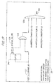
- FIG. 17 is a diagram illustrating the inhibiting signal generation circuit 23 when the present proposal is applied to a processor having an SMT function. Inhibition conditions added in the second modification will be described with reference to FIG. 17 .
- Inhibition conditions (1) to (3) illustrated in FIG. 17 correspond to the cases (1) to (3), respectively, illustrated in the first modification as examples of a case where a branch instruction fails to be completed in a predetermined number of cycles.
- a NEXT_U_STRAND_ID signal 117 indicates a thread in which U cycle completion processing is to be performed next.
- the second modification illustrates a case where the number of threads is two. That is, in this case, the value of the NEXT_U_STRAND_ID signal 117 is, for example, 0 or 1.
- the NEXT_U_STRAND_ID signal 117 is saved as a NEXT_U_STRAND_ID_1TD signal 118 in a latch 24e.
- the latch 24e is an example of a thread management unit. If the value of the NEXT_U_STRAND_ID signal 117 in the current cycle is different from the value of the NEXT_U_STRAND_ID_1TD signal 118 for an immediately preceding cycle saved in the latch 24e, thread switching has occurred.
- the NEXT_U_STRAND_ID signal 117 and the NEXT_U_STRAND_ID_1TD signal 118 are examples of a thread identifier.
- an XOR circuit 116 outputs an inhibiting signal to an OR circuit 115c.
- the OR circuit 115c generates an INH_SET_FORCE_BR_COMP signal 102 (abbreviated as INH in FIG. 17 ).
- the mechanism for sensing thread switching is an example of predetermined condition information.
- thread switching can be sensed.
- the present proposal can be applied to a processor having an SMT function.
- first modification and the second modification can be combined.
- This case can support SMT while supporting a case where a branch instruction fails to be completed in a predetermined number of cycles.
Landscapes
- Engineering & Computer Science (AREA)
- Software Systems (AREA)
- Theoretical Computer Science (AREA)
- Physics & Mathematics (AREA)
- General Physics & Mathematics (AREA)
- General Engineering & Computer Science (AREA)
- Computational Mathematics (AREA)
- Mathematical Analysis (AREA)
- Mathematical Optimization (AREA)
- Pure & Applied Mathematics (AREA)
- Advance Control (AREA)
- Executing Machine-Instructions (AREA)
Abstract
An arithmetic processing unit including a branch instruction execution management unit configured to accumulate a branch instruction waiting so be executed and to manage completion of a branch instruction, a completion processing waiting storage unit configured to accumulate an identifier of an instruction waiting for completion processing according to an execution sequence of a program, a completion processing unit configured to activate resource update processing due to execution of a branch instruction when the completion processing unit receives an execution completion report for the branch instruction from the branch instruction execution management unit and identified by the identifier, and a promotion unit configured to, when an identifier accumulated at the top of the completion processing waiting storage unit indicates a branch instruction, cause the completion processing unit to activate the resource update processing without waiting for the execution completion report for the branch instruction.
Description
- The embodiments discussed herein are related to an arithmetic processing unit and a method for controlling the arithmetic processing unit.
-
FIG. 1 is a diagram illustrating the configuration of a superscalar processor. The configuration of the superscalar processor will be described with reference toFIG. 1 . The superscalar processor illustrated inFIG. 1 has an instructionfetch address generator 1 which generates an instruction fetch address, abranch prediction mechanism 2 which performs branch prediction for a branch instruction, aprimary instruction cache 3 which caches an instruction, aninstruction decoder 4 which decodes a fetched instruction, reservation stations (anRSA 5, an RSE 6, an RSF 7, and an RSBR 8) which accumulate a decoded instruction, a commit stack entry (CSE) 9 which performs completion processing of an instruction, anoperand address generator 10 which generates an operand address, aprimary data cache 11 which stores data,arithmetic units 12 which execute a decoded instruction, update buffers (a fixed-point update buffer 13 and a floating-point update buffer 14) which store a result of executing an operation, registers (a fixed-point register 15 and a floating-point register 16) which are used at the time of execution of an operation, program counters (a NEXT program counter (NEXT PC) 17 and a program counter (PC) 18) which hold the address of an instruction, and a condition code (CC)register 19 which stores a condition code used for condition determination. - Execution of an instruction in the processor in
FIG. 1 will be illustrated in the manner below. An instruction is fetched from theprimary instruction cache 3 according to the execution sequence of a program. The fetched instruction is decoded by theinstruction decoder 4. The instruction decoded by theinstruction decoder 4 is accumulated in a storage having a queue structure called a reservation station. A reservation station is prepared for each type of instruction. The reservation station for execution (RSE) 6 for fixed-point calculation, the reservation station for branch (RSBR) 8 for a branch instruction, and the like are examples of a reservation station. Instructions accumulated in the reservation stations are executed out of order from the first to be ready for execution. - Instructions decoded by the
instruction decoder 4 are each assigned an instruction identification (IID) according to the order the instructions are decoded. An IID is an example of an identifier for instruction identification. The instructions assigned IIDs are sent to theCSE 9 in the order the IIDs are assigned. The CSE 9 is an example of a circuit which performs completion processing of an instruction. The CSE 9 has a storage having a queue structure in which instructions decoded by theinstruction decoder 4 are accumulated in the order the instructions are to be executed and a completion processing circuit. The completion processing circuit of theCSE 9 receives completion reports for processes from theRSBR 8, thearithmetic units 12, theprimary data cache 11, and the like. The completion processing circuit of theCSE 9 performs instruction completion processing on the basis of a received completion report and information accumulated in the queue. The instruction completion processing is called COMMIT. An instruction decoded by theinstruction decoder 4 is accumulated in the queue of the CSE 9. The instruction accumulated in the queue of theCSE 9 waits for a report on completion of instruction processing. Completion reports for instructions accumulated in the reservation stations and executed out of order are sent to the CSE 9. The completion processing circuit of theCSE 9 subjects an instruction corresponding to a completion report to COMMIT among instructions waiting for completion reports accumulated in the queue of theCSE 9 according to the original execution sequence of a program. When the instruction is subjected to COMMIT, resource updating is performed. -
FIG. 2 is a chart illustrating processing of a branch instruction. The branch instruction processing will be described with reference toFIG. 2 . An instruction is fetched from theprimary instruction cache 3. The fetched instruction is decoded by theinstruction decoder 4. The decoded instruction is assigned an IID. The instruction assigned the IID is accumulated in aqueue 9A for instructions waiting for completion processing of the CSE 9 (hereinafter referred to as thequeue 9A of the CSE 9). Thequeue 9A of the CSE 9 is an example of a completion processing waiting storage unit in which the identifiers of instructions waiting for completion processing are accumulated according to the execution sequence of a program. An instruction which is determined to be a branch instruction as a result of the decoding is accumulated in theRSBR 8. A branch instruction accumulated in theRSBR 8 waits for branch determination in the branch instruction to become possible. In the branch instruction, whether a branch is taken (TAKEN) or is not taken (NOT TAKEN) is settled (resolved), depending on a value of a register called the condition code (CC)register 19. Thus, a resolution in a subsequent branch instruction comes after completion of an instruction which changes the condition code. Note that theCC register 19 is updated when the instruction that changes the condition code is subjected to COMMIT. However, it takes time to perform branch determination in theRSBR 8 after theCC register 19 is updated. The condition code calculated in thearithmetic unit 12 may be sent from thearithmetic unit 12 to theRSBR 8. TheRSBR 8 may perform branch determination on the basis of the condition code sent from thearithmetic unit 12. When branch determination becomes possible, theRSBR 8 performs branch determination. TheRSBR 8 sends a completion report for a branch instruction and resource update information to acompletion processing circuit 9B of the CSE 9. Examples of the resource update information include TAKEN and NOT TAKEN described above. TheRSBR 8 is an example of a branch instruction execution management unit which manages completion of a branch instruction. Thecompletion processing circuit 9B of the CSE 9 receives the report from theRSBR 8, performs completion processing of a branch instruction corresponding to the completion report among instructions waiting for completion reports accumulated in thequeue 9A of the CSE 9, and performs resource updating. Thecompletion processing circuit 9B of theCSE 9 is an example of a completion processing unit which activates resource update processing accompanying execution of a branch instruction. -
FIG. 3 is a chart illustrating a flow of processing from an instruction which changes the condition code to a branch instruction in the superscalar processor. The abscissa axis inFIG. 3 represents a clock of the processor. The ordinate axis inFIG. 3 represents the type of an instruction to be executed. InFIG. 3 , a subcc instruction is illustrated as an instruction which changes the condition code. The description "TOQ-IID" inFIG. 3 denotes the IID of an instruction at the top of thequeue 9A of theCSE 9. The description "subcc INSTRUCTION(IID=0x10)" denotes that the IID of a subcc instruction illustrated inFIG. 3 is 0x10. The description "CC(EU→IU)" denotes that the condition code as a result of the subcc instruction is transmitted from thearithmetic unit 12 to theRSBR 8. Reference character EU denotes thearithmetic unit 12 while reference character IU denotes theRSBR 8. The description "SUBSEQUENT BRANCH INSTRUCTION(IID=0x11)" denotes that the IID of a branch instruction which performs branch determination on the basis of the condition code settled by the subcc instruction is 0x11. The description "RESOLVE(IID=0x11)" denotes that whether a branch in the subsequent branch instruction (IID=0x11) is taken or not taken is settled. Reference character BR_COMP denotes an example of a signal which indicates completion of the subsequent branch instruction (IID=0x11). - A subcc instruction is executed in a five-stage pipeline, Priority (P), Buffer 1 (B1), Buffer 2 (B2), Execute (X), Update (U), and Write (W). In a P cycle, the reservation stations each select one with a high priority among from instructions waiting to be executed and send the instruction to the
arithmetic unit 12. In B1 and B2 cycles, thearithmetic unit 12 prepares itself to execute the instruction sent from the reservation station. In an X cycle, thearithmetic unit 12 executes the instruction. In a U cycle, theCSE 9 performs instruction completion determination. In a W cycle, update signals for resources update the resources, such as the program counter 18. - A branch instruction is executed in a four-stage pipeline, Resolve (R), Complete (C), Update (U), and Write (W). In an R cycle, whether a branch in the branch instruction is taken (TAKEN) or not taken (NOT TAKEN) is settled. In a C cycle, an instruction completion report is sent from the
RSBR 8 to thecompletion processing circuit 9B of theCSE 9. In a U cycle, theCSE 9 performs instruction completion determination. In a W cycle, update signals for the resources update the resources. - The processing in each cycle will be described below with reference to
FIG. 3 . In a seventh cycle, the condition code as a result of the subcc instruction is sent from thearithmetic unit 12 to theRSBR 8. In an eighth cycle, branch determination in the subsequent branch instruction is performed on the basis of the condition code sent in the seventh cycle. In a ninth cycle, the branch instruction is completed. ABR_COMP signal 105 indicating completion of a branch instruction is generated. In a tenth cycle, a resource update signal is generated. In an 11th cycle, update signals for the resources update the resources on the basis of a WRITE signal. - [Patent document 1] Japanese Laid-Open Patent Publication No.
2004-021711 - The
CSE 9 waits for the condition code to be settled in order to complete a branch instruction. The condition code is settled on the basis of, e.g., a result of executing a different instruction. For this reason, dependence of a branch instruction on a different instruction is likely to develop. A branch instruction is thus likely to wait for completion. As a result, the performance of the processor may decrease. - Under the circumstances, it is an object of the present proposal to speed up completion of a branch instruction.
- The present proposal discloses an arithmetic processing unit including a branch instruction execution management unit configured to accumulate a branch instruction waiting to be executed and to manage completion of a branch instruction that is executed when a branch condition in the branch instruction is settled, a completion processing waiting storage unit configured to accumulate an identifier of an instruction waiting for completion processing according to an execution sequence of a program, a completion processing unit configured to activate resource update processing due to execution of a branch instruction when the completion processing unit receives an execution completion report for the branch instruction from the branch instruction execution management unit and identified by the identifier, and a promotion unit configured to, when an identifier accumulated at the top of the completion processing waiting storage unit indicates a branch instruction, cause the completion processing unit to activate the resource update processing without waiting for the execution completion report for the branch instruction.
- According to the present proposal, completion of a branch instruction can be speeded up.
-
-
FIG. 1 is a diagram illustrating the configuration of a superscalar processor; -
FIG. 2 is a chart illustrating processing of a branch instruction; -
FIG. 3 is a chart illustrating a flow of processing from an instruction which changes a condition code to a branch instruction in the superscalar processor; -
FIG. 4 is a diagram illustrating a plurality of processors, memories connected to the processors, and an interconnect control unit which performs I/O control between the processors and an external device; -
FIG. 5 is a chart illustrating a flow from an instruction which changes a condition code to COMMIT processing of a branch instruction in a system according to a comparative example; -
FIG. 6 is a chart illustrating the details of processing by components in each cycle in the system according to the comparative example; -
FIG. 7 is a diagram illustrating a COMMIT processing circuit of a processor according to the comparative example; -
FIG. 8 is a chart illustrating a flow of processing from an instruction which changes a condition code to a branch instruction in a system according to a first embodiment; -
FIG. 9 is a diagram illustrating the configuration of COMMIT processing according to the first embodiment; -
FIG. 10 is a diagram illustrating a COMMIT processing circuit of a processor according to the first embodiment; -
FIG. 11 is a diagram illustrating the configuration of COMMIT processing according to a first modification; -
FIG. 12 is a diagram illustrating a COMMIT processing circuit of a processor according to the first modification; -
FIG. 13 is a chart illustrating pipeline processing from an instruction which changes a condition code to a branch instruction in a system according to the first modification; -
FIG. 14 is a chart illustrating the details of processing by components in each cycle in the first modification; -
FIG. 15 is a chart illustrating pipeline processing from an instruction which changes the condition code to a branch instruction when an inhibiting signal generation circuit generates an inhibiting signal in the first modification; -
FIG. 16 is a chart illustrating the details of processing by the components in each cycle when the inhibiting signal is generated by an inhibitingsignal generation circuit 23, in the first modification; and -
FIG. 17 is a diagram illustrating an inhibiting signal generation circuit when the present proposal is applied to a processor having an SMT function. - Embodiments to be disclosed in the present proposal will be described below with reference to the drawings. The configurations of the embodiments below are illustrative only, and the present proposal is not limited to the configurations of the embodiments disclosed below.
- A system will be illustrated as a comparative example which performs COMMIT processing of a branch instruction after receiving a completion report for the branch instruction.
FIG. 4 is a diagram illustrating a plurality of processors (aCPU 401 and a CPU 402), memories (amemory 403 and a memory 404) connected to the processors, and aninterconnect control unit 405 which performs I/O control between the processors and an external device. The system according to the comparative example can be applied to, for example, theCPU FIG. 4 . The system according to the comparative example may be a superscalar processor having an out-of-order function and a pipeline function as illustrated inFIG. 1 . -
FIG. 5 is a chart illustrating a flow from an instruction which changes a condition code to COMMIT processing of a branch instruction in the system according to the comparative example. The abscissa axis inFIG. 5 represents a clock of a processor. The ordinate axis inFIG. 5 represents the type of an instruction to be executed. InFIG. 5 , a subcc instruction is illustrated as an instruction which changes the condition code. The meanings of the descriptions "TOQ-IID," "subcc INSTRUCTION(IID=0x11)," "CC(EU→IU)," and "SUBSEQUENT BRANCH INSTRUCTION(IID=0x11)" are the same as those inFIG. 3 , and a description thereof will be omitted. - COMMIT processing of a branch instruction in the system according to the comparative example will be described with reference to
FIG. 5 . In a seventh cycle, the condition code as a result of a subcc instruction is sent from anarithmetic unit 12 to anRSBR 8. In an eighth cycle, branch determination in a subsequent branch instruction is performed on the basis of the condition code sent in the seventh cycle. In a ninth cycle, the branch instruction is completed. In a tenth cycle, a resource update signal is generated. In an eleventh cycle, update signals for resources update the resources on the basis of a WRITE signal. -
FIG. 6 is a chart illustrating the details of processing by components in each cycle in the system according to the comparative example. The abscissa axis inFIG. 6 represents a clock of the processor. The ordinate axis inFIG. 6 represents a component to perform processing. - Processing performed by the components in each cycle will be described with reference to
FIG. 6 . In the seventh cycle, the condition code as the result of the subcc instruction is sent from thearithmetic unit 12 to the RSBR 8 (S61). In the eighth cycle, theRSBR 8 determines whether to branch on the basis of a branch condition based on the details of the instruction in theRSBR 8 and the condition code (S62). Upon completion of the subcc instruction, the subsequent branch instruction becomes the top (hereinafter referred to as a TOQ-CSE) in aqueue 9A of aCSE 9. The branch instruction as the TOQ-CSE waits for aBR_COMP signal 105 which is a completion report from the RSBR 8 (S63). In the ninth cycle, theRSBR 8 selects a piece of branch determination information to be sent to theCSE 9 among from pieces of branch determination information. TheRSBR 8 generates theBR_COMP signal 105 and a BR_TAKEN signal on the basis of the selected piece of branch determination information (S64). In thequeue 9A of theCSE 9, the branch instruction as the TOQ-CSE waits for COMMIT processing. Upon receipt of theBR_COMP signal 105 and the BR_TAKEN signal, acompletion processing circuit 9B of theCSE 9 generates a TOQ_BR_COMP signal and a TOQ_BR_TAKEN signal (S65). From the TOQ_BR_COMP signal, thecompletion processing circuit 9B of theCSE 9 determines that the branch instruction is completed. Thecompletion processing circuit 9B of theCSE 9 generates a TOQ_COMMIT signal which is a COMMIT signal. Thecompletion processing circuit 9B of theCSE 9 further generates a WRITE signal which is a resource update signal on the basis of the TOQ_BR_TAKEN signal and the like (S66). Update signals for the resources update the resources on the basis of the WRITE signal (S67). -
FIG. 7 is a diagram illustrating a COMMIT processing circuit of the processor according to the comparative example.FIG. 7 illustrates a portion corresponding to theCSE 9 and theRSBR 8 inFIG. 1 . As illustrated inFIG. 7 , theCSE 9 according to the comparative example has thequeue 9A of theCSE 9 and thecompletion processing circuit 9B of theCSE 9. Thecompletion processing circuit 9B of theCSE 9 has a WRITEsignal generation circuit 20, latches 24a to 24c, ANDcircuits 114a to 114c, and anOR circuit 115a. - COMMIT processing according to the comparative example will be described with reference to
FIG. 7 . If a branch instruction is a TOQ-CSE instruction, thequeue 9A of theCSE 9 generates aTOQ_BR_USE signal 104 indicating that the branch instruction is a TOQ-CSE instruction. TheTOQ_BR_USE signal 104 is saved in thelatch 24a. When a branch instruction is completed, theRSBR 8 generates theBR_COMP signal 105 indicating completion of a branch instruction. If a branch instruction in theRSBR 8 is a TOQ-CSE instruction, aTOQ_BR_COMP_SEL signal 106 is generated. TheTOQ_BR_COMP_SEL signal 106 is a signal indicating that a branch instruction executed in theRSBR 8 is a TOQ-CSE instruction. TheTOQ_BR_COMP_SEL signal 106 is generated in thecompletion processing circuit 9B of theCSE 9 if, for example, the IID of an instruction, for which theBR_COMP signal 105 is sent from theRSBR 8, and the IID of a TOQ-CSE instruction match. The ANDcircuit 114b performs an AND operation between theTOQ_BR_COMP_SEL signal 106 and theBR_COMP signal 105 sent from theRSBR 8 to generate aTOQ_BR_COMP signal 107. TheTOQ_BR_COMP signal 107 is a signal indicating completion of a TOQ-CSE branch instruction. TheTOQ_BR_COMP signal 107 is saved in thelatch 24b. The ANDcircuit 114c performs an AND operation between theTOQ_BR_COMP_SEL signal 106 and aBR_TAKEN signal 108 from theRSBR 8 to generate aTOQ_BR_TAKEN signal 109. TheTOQ_BR_TAKEN signal 109 is a signal indicating that a branch in a TOQ-CSE branch instruction is taken (TAKEN). TheTOQ_BR_TAKEN signal 109 is saved in thelatch 24c. - It can be seen from the
TOQ_BR_COMP signal 107 saved in thelatch 24b that a TOQ-CSE branch instruction is completed. It can be seen, if theTOQ_BR_USE signal 104 is not asserted, that a TOQ-CSE instruction is not a branch instruction. For this reason, theOR circuit 115a performs an OR operation between a result of performing a NOT operation on theTOQ_BR_USE signal 104 saved in thelatch 24a and theTOQ_BR_COMP signal 107 saved in thelatch 24b to generate aTOQ_BR_COMMIT signal 111. TheTOQ_BR_COMMIT signal 111 is an example of a signal indicating that COMMIT processing of a TOQ-CSE branch instruction may be performed. - The AND
circuit 114a generates aTOQ_COMMIT signal 110 indicating completion of a TOQ-CSE instruction. TheTOQ_COMMIT signal 110 is generated through an AND operation among theTOQ_BR_COMMIT signal 111, aTOQ_EU_COMMIT signal 112, and aTOQ_FCH_COMMIT signal 113. - The
TOQ_EU_COMMIT signal 112 is an example of a signal indicating that COMMIT processing of a TOQ-CSE instruction executed in an execution unit of the processor may be performed. An instruction which is executed in the execution unit of the processor will be referred to as an EU instruction hereinafter. TheTOQ_EU_COMMIT signal 112 is generated through, for example, a logical operation. An OR operation between a - TOQ_EU_USE signal and a TOQ_EU_COMP signal is an example of the logical operation that generates theTOQ_EU_COMMIT signal 112. The TOQ_EU_COMP signal is an example of a signal indicating that a TOQ-CSE EU instruction is completed. The -TOQ_EU_USE signal is an example of a signal indicating that a TOQ-CSE instruction is not an EU instruction. If a TOQ-CSE instruction is a branch instruction, the TOQ-CSE instruction is not an EU instruction, and the -TOQ_EU_USE signal is generated. As a result, theTOQ_EU_COMMIT signal 112 is generated. - The
TOQ_FCH_COMMIT signal 113 is an example of a signal indicating that COMMIT processing of a TOQ-CSE instruction using an FCH port may be performed. An instruction using an FCH port will be referred to as an FCH instruction hereinafter. TheTOQ_FCH_COMMIT signal 113 is generated through, for example, a logical operation. An OR operation between a -TOQ_FCH_USE signal and a TOQ_FCH_COMP signal is an example of the logical operation that generates theTOQ_FCH_COMMIT signal 113. The TOQ_FCH_COMP signal is an example of a signal indicating that a TOQ-CSE FCH instruction is completed. The -TOQ_FCH_USE signal is an example of a signal indicating that a TOQ-CSE instruction is not an FCH instruction. If a TOQ-CSE instruction is a branch instruction, the TOQ-CSE instruction is not an FCH instruction, and the -TOQ_FCH_USE signal is generated. As a result, theTOQ_FCH_COMMIT signal 113 is generated. Note that a LOAD instruction and a STORE instruction are examples of an FCH instruction. - That is, if the
TOQ_BR_COMMIT signal 111, theTOQ_EU_COMMIT signal 112, and theTOQ_FCH_COMMIT signal 113 are generated, it can be seen that a TOQ-CSE instruction is completed. Thus, the ANDcircuit 114a generates theTOQ_COMMIT signal 110 by performing an AND operation among theTOQ_BR_COMMIT signal 111, theTOQ_EU_COMMIT signal 112, and theTOQ_FCH_COMMIT signal 113. - The WRITE
signal generation circuit 20 generates a WRITE signal which is resource update information on the basis of theTOQ_COMMIT signal 110 and theTOQ_BR_TAKEN signal 109 saved in thelatch 24c. Update signals for the resources update the resources on the basis of the WRITE signal. - In the comparative example, completion processing of a branch instruction is performed by waiting for the BR_COMP signal 105 from the
RSBR 8. - In the comparative example, COMMIT processing is performed after completion of a branch instruction. A first embodiment illustrates COMMIT processing of a branch instruction which is performed without waiting for completion of the branch instruction. A system according to the first embodiment can be applied to, for example, the
CPU FIG. 4 . The system according to the first embodiment may be a superscalar processor having an out-of-order function and a pipeline function as illustrated inFIG. 1 . The processor inFIG. 1 and theCPUs FIG. 4 are examples of an arithmetic processing unit. A branch instruction is assumed to be completed in a predetermined number of cycles after a condition code is settled. The first embodiment will illustrate a case where the predetermined number of cycles are two cycles. -
FIG. 8 is a chart illustrating a flow of processing from an instruction which changes the condition code to a branch instruction in the system according to the first embodiment. The abscissa axis inFIG. 8 represents a clock of a processor. The ordinate axis inFIG. 8 represents the type of an instruction to be executed. A subcc instruction is illustrated here as an instruction which changes the condition code. TOQ_BR_COMP is an example of a signal indicating completion of a subsequent branch instruction as a TOQ-CSE. The meanings of the descriptions "TOQ-IID," "subcc INSTRUCTION(IID=0x11)," "CC(EU→IU)," "SUBSEQUENT BRANCH INSTRUCTION(IID=0x11)," "RESOLVE(IID=0x11)," and "BR_COMP" are the same as those inFIG. 3 , and a description thereof will be omitted. - COMMIT processing of a branch instruction according to the first embodiment will be described with reference to
FIG. 8 . In a seventh cycle, the condition code as a result of a subcc instruction is sent from anarithmetic unit 12 to anRSBR 8. In an eighth cycle, branch determination in a subsequent branch instruction is performed on the basis of the condition code sent in the seventh cycle. In a ninth cycle, the branch instruction is completed. Without waiting for aBR_COMP signal 105 to be generated, aTOQ_BR_COMP signal 107 indicating completion of a TOQ-CSE branch instruction is generated. Upon completion of the branch instruction, theBR_COMP signal 105 indicating completion of a branch instruction is generated. A WRITE signal is generated on the basis of aBR_TAKEN signal 108 and the like. In a tenth cycle, update signals for resources update the resources on the basis of the WRITE signal. -
FIG. 9 is a diagram illustrating the configuration of COMMIT processing according to the first embodiment.FIG. 9 illustrates a portion corresponding to theRSBR 8 and theCSE 9 of the processor illustrated inFIG. 1 . As illustrated inFIG. 9 , the system according to the first embodiment has thequeue 9A of theCSE 9, thecompletion processing circuit 9B of theCSE 9, a branch instruction COMMITspeedup circuit 22 which speeds up COMMIT of a branch instruction, and aselector 25. - If a branch instruction becomes a TOQ-CSE, the
queue 9A of theCSE 9 generates aTOQ_BR_USE signal 104. Upon receipt of theTOQ_BR_USE signal 104, the branch instruction COMMITspeedup circuit 22 generates aSET_FORCE_BR_COMP signal 101 which starts completion processing of a branch instruction. In the generation of theSET_FORCE_BR_COMP signal 101, the branch instruction COMMITspeedup circuit 22 need not wait for theBR_COMP signal 105 that is a branch instruction completion signal. The branch instruction COMMITspeedup circuit 22 is an example of a promotion unit. - If a TOQ-CSE instruction is a branch instruction, an instruction executed before the branch instruction which changes the condition code is presumed to have been completed. The condition code used for branch determination is presumed to be settled. The branch instruction is thus expected to be completed in the predetermined number of cycles. The first embodiment illustrates a case where a branch instruction is completed in two cycles as the predetermined number of cycles after the condition code is settled. For this reason, if a branch instruction becomes a TOQ-CSE instruction, the branch instruction is expected to be completed in a next cycle. When a branch instruction becomes a TOQ-CSE instruction, the
TOQ_BR_COMP signal 107 indicating completion of a branch instruction in theCSE 9 is generated. Thecompletion processing circuit 9B of theCSE 9 need not wait for theBR_COMP signal 105 indicating completion of a branch instruction from theRSBR 8. As a result, COMMIT of a branch instruction is performed one cycle earlier than in the comparative example. For this reason, transmission of resource update information to a WRITEsignal generation circuit 20 with the same timing as in the comparative example is too late for generation of a WRITE signal. Thus, in the first embodiment, a circuit which transmits resource update information to the WRITEsignal generation circuit 20 one cycle earlier is added. -
FIG. 10 is a diagram illustrating a COMMIT processing circuit of the system according to the first embodiment.FIG. 10 illustrates a portion corresponding to theCSE 9 and theRSBR 8 inFIG. 1 . As illustrated inFIG. 10 , theCSE 9 according to the first embodiment has thequeue 9A of theCSE 9 and thecompletion processing circuit 9B of theCSE 9. Thecompletion processing circuit 9B of theCSE 9 has the WRITEsignal generation circuit 20, latches 24a to 24d, ANDcircuits 114a to 114c, andOR circuits - COMMIT processing of the system according to the first embodiment will be described with reference to
FIG. 10 . As described above, if a branch instruction is a TOQ-CSE instruction, the branch instruction is presumed to be completed in a next cycle. When theTOQ_BR_USE signal 104 is generated, theOR circuit 115b generates theTOQ_BR_COMP signal 107 without waiting for theBR_COMP signal 105. TheTOQ_BR_COMP signal 107 is saved in thelatch 24b. The lack of the need to wait for theBR_COMP signal 105 allows theTOQ_BR_COMP signal 107 to be generated one cycle earlier than in the comparative example. How theTOQ_COMMIT signal 110 is generated afterward is the same as in the comparative example, and a description thereof will be omitted. - The
TOQ_BR_USE signal 104 is saved as theSET_FORCE_BR_COMP signal 101 in thelatch 24d. TheSET_FORCE_BR_COMP signal 101 saved in thelatch 24d is transmitted as aFORCE_BR_COMP signal 101a to theselector 25. Upon receipt of theFORCE_BR_COMP signal 101a, theselector 25 selects a path which bypasses thelatch 24c and transmits theBR_TAKEN signal 108 to the WRITEsignal generation circuit 20. The bypassing of thelatch 24c allows one-cycle earlier generation of a WRITE signal. - According to the first embodiment, completion processing of a branch instruction can be started without waiting for the BR_COMP signal 105 from the
RSBR 8. It is thus possible to make the processing cycle of a branch instruction one cycle shorter than in the comparative example. - In the first embodiment, completion of a branch instruction is speeded up on the assumption that a branch instruction is completed in a predetermined number of cycles. A first modification discloses a configuration in which the present proposal is applied to a case where a branch instruction is not completed in a predetermined number of cycles.
- The branch instruction COMMIT
speedup circuit 22 generates theSET_FORCE_BR_COMP signal 101 on the assumption that a branch instruction is completed in a predetermined number of cycles. Thus, if a branch instruction is not completed in the predetermined number of cycles, the branch instruction COMMITspeedup circuit 22 preferably does not generate theSET_FORCE_BR_COMP signal 101. For this reason, in the first modification, an inhibiting signal generation circuit which inhibits operation of the branch instruction COMMITspeedup circuit 22 if a branch instruction is not completed in a predetermined number of cycles is added. The inhibiting signal generation circuit is an example of an inhibition unit. - Examples of a case where a branch instruction fails to be completed in a predetermined number of cycles even if the branch instruction is a TOQ-CSE include the cases (1) to (3) below. A signal which gives notice of the situations (1) to (3) below is an example of predetermined condition information.
- (1) If a branch prediction for a branch instruction is wrong, an instruction is re-fetched. In this case, the present embodiment needs preparation to re-fetch an instruction and the like, and a completion report for the branch instruction may fail to be made in a predetermined number of cycles. Thus, a branch instruction may fail to be completed in the predetermined number of cycles.
- (2) In the case of a register-indirect branch instruction, an operation in an exceptional case may occur, depending on the value of a branch destination address. This involves time to handle the exceptional case. For this reason, a branch instruction may fail to be completed in a predetermined number of cycles. A JUMP instruction and a RETURN instruction are examples of a register-indirect branch instruction.
- (3) A case is conceivable where a branch instruction doubles as a function of settling a condition code. A BPR instruction is an example of a branch instruction doubling as the function of settling the condition code.
- In this case, even if a TOQ-CSE instruction is a branch instruction, a condition code has not yet been settled. Information for branch determination may be insufficient.
- In each of the cases (1) to (3) above, a branch instruction may fail to be completed in a predetermined number of cycles. Operation of the branch instruction COMMIT
speedup circuit 22 needs to be inhibited. For this reason, the inhibiting signal generation circuit according to the first modification transmits an inhibiting signal to the branch instruction COMMITspeedup circuit 22 in each of the cases (1) to (3) above. Upon receipt of the inhibiting signal, the branch instruction COMMITspeedup circuit 22 does not generate theSET_FORCE_BR_COMP signal 101. As a result, aTOQ_BR_COMMIT signal 111 is generated after reception of the BR_COMP signal 105 from theRSBR 8. -
FIG. 11 is a diagram illustrating the configuration of COMMIT processing according to the first modification.FIG. 11 illustrates a portion corresponding to theCSE 9 and theRSBR 8 inFIG. 1 . The first modification is obtained by adding an inhibitingsignal generation circuit 23 for the branch instruction COMMIT speedup circuit (hereinafter referred to as the inhibiting signal generation circuit 23) to the configuration according to the first embodiment. The inhibitingsignal generation circuit 23 is an example of a circuit which inhibits operation of the branch instruction COMMITspeedup circuit 22. In the first modification, a case is assumed where a branch instruction is completed in two cycles after a condition code is settled. The same components as those in the first embodiment are denoted by the same reference numerals, and a description thereof will be omitted. - The configuration of the COMMIT processing according to the first modification will be described with reference to
FIG. 11 . TheRSBR 8 transmits information on the type of a branch instruction and branch misprediction information to the inhibitingsignal generation circuit 23. It is determined from the report from theRSBR 8 that the branch instruction will not be completed in the predetermined number of cycles, the inhibitingsignal generation circuit 23 transmits anINH_SET_FORCE_BR_COMP signal 102 which is a signal inhibiting operation of the branch instruction COMMITspeedup circuit 22 to the branch instruction COMMITspeedup circuit 22. The INH_SET_FORCE_BR_COMP signal 102 (abbreviated as an INH signal inFIG. 11 ) is an example of an inhibiting signal. - Upon receipt of the
INH_SET_FORCE_BR_COMP signal 102, the branch instruction COMMITspeedup circuit 22 does not generate theSET_FORCE_BR_COMP signal 101. As a result, theTOQ_BR_COMMIT signal 111 is generated after reception of the BR_COMP signal 105 from theRSBR 8. Resource update information from theRSBR 8 is transmitted by theselector 25 to the WRITEsignal generation circuit 20 via thelatch 24c. -
FIG. 12 is a diagram illustrating a COMMIT processing circuit of a processor according to the first modification. The COMMIT processing according to the first modification will be described with reference toFIG. 12 . The same components as those in the first embodiment are denoted by the same reference numerals, and a description thereof will be omitted. The inhibitingsignal generation circuit 23 generates theINH_SET_FORCE_BR_COMP signal 102 on the basis of information on a branch misprediction and the type of a branch instruction from theRSBR 8. An ANDcircuit 114d of the branch instruction COMMITspeedup circuit 22 performs an AND operation between a result of a NOT operation on theINH_SET_FORCE_BR_COMP signal 102 and theTOQ_BR_USE signal 104. As a result, if theINH_SET_FORCE_BR_COMP signal 102 is asserted, theSET_FORCE_BR_COMP signal 101 is not generated. With this processing, in the case of a branch misprediction or the like, theTOQ_BR_COMMIT signal 111 is generated after reception of the BR_COMP signal 105 from theRSBR 8. Resource update information from theRSBR 8 is transmitted by theselector 25 to the WRITEsignal generation circuit 20 via thelatch 24c. -
FIG. 13 is a chart illustrating pipeline processing from an instruction which changes the condition code to a branch instruction in the system according to the first modification. The abscissa axis inFIG. 13 represents a clock of the processor. The ordinate axis inFIG. 13 represents the type of an instruction to be executed. InFIG. 13 , a subcc instruction is illustrated as the instruction that changes the condition code. The meanings of the descriptions "TOQ-IID," "subcc INSTRUCTION(IID=0x11)," "CC (EU->IU)," and "SUBSEQUENT BRANCH INSTRUCTION(IID=0x11)" are the same as those inFIG. 3 , and a description thereof will be omitted. - COMMIT processing of a branch instruction in the system according to the first modification will be described with reference to
FIG. 13 . In a seventh cycle, the condition code as a result of a subcc instruction is sent from thearithmetic unit 12 to theRSBR 8. In an eighth cycle, branch determination in a subsequent branch instruction is performed on the basis of the condition code sent in the seventh cycle. In a ninth cycle, the branch instruction is completed. If theINH_SET_FORCE_BR_COMP signal 102 is not generated, theTOQ_BR_COMP signal 107 indicating completion of a TOQ-CSE branch instruction is generated without waiting for theBR_COMP signal 105 to be generated. Upon the completion of the branch instruction, theBR_COMP signal 105 indicating completion of a branch instruction is generated. A WRITE signal is generated on the basis of theBR_TAKEN signal 108 and the like. In a tenth cycle, update signals for resources update the resources on the basis of the WRITE signal. -
FIG. 14 is a chart illustrating the details of processing by components in each cycle in the first modification. The abscissa axis inFIG. 14 represents a clock of the processor. The ordinate axis inFIG. 14 represents a component to perform processing. - Processing performed by the components in each cycle will be described with reference to
FIG. 14 . In the eighth cycle, the subcc instruction is completed, and the subsequent branch instruction becomes a TOQ-CSE. If there is no INH_SET_FORCE_BR_COMP signal 102 from the inhibitingsignal generation circuit 23, theSET_FORCE_BR_COMP signal 101 is generated by the branch instruction COMMIT speedup circuit 22 (S141). A set signal for theTOQ_BR_COMP signal 107 is generated on the basis of the SET_FORCE_BR_COMP signal 101 (S142). In the ninth cycle, theCSE 9 having received theTOQ_BR_COMP signal 107 generates theTOQ_BR_COMMIT signal 111. If a branch instruction is a TOQ-CSE, since the branch instruction is not an EU instruction or an FCH instruction, theTOQ_EU_COMMIT signal 112 and theTOQ_FCH_COMMIT signal 113 are generated. An AND operation among the signals, theTOQ_BR_COMMIT signal 111, theTOQ_EU_COMMIT signal 112, and theTOQ_FCH_COMMIT signal 113, is performed to generate theTOQ_COMMIT signal 110. Resource update information is transmitted from theRSBR 8 to the WRITEsignal generation circuit 20. Examples of the resource update information include theBR_TAKEN signal 108. The WRITEsignal generation circuit 20 combines theTOQ_COMMIT signal 110 and the update information received from theRSBR 8 to generate a WRITE signal (S143). In the tenth cycle, the branch instruction is completed, and the resources are updated on the basis of the WRITE signal (S144). - Note that, as described above, a branch instruction may fail to be completed in the predetermined number of cycles even if the branch instruction is a TOQ-CSE. If a branch instruction is not completed in the predetermined number of cycles, the branch instruction COMMIT
speedup circuit 22 does not generate theSET_FORCE_BR_COMP signal 101. In this case, the inhibitingsignal generation circuit 23 generates an inhibiting signal which inhibits generation of theSET_FORCE_BR_COMP signal 101. TheINH_SET_FORCE_BR_COMP signal 102 is an example of the inhibiting signal. As a result, theTOQ_BR_COMMIT signal 111 is generated after reception of the BR_COMP signal 105 from theRSBR 8. -
FIG. 15 is a chart illustrating pipeline processing from an instruction which changes the condition code to a branch instruction when the inhibitingsignal generation circuit 23 generates an inhibiting signal in the first modification. The abscissa axis inFIG. 15 represents a clock of the processor. The ordinate axis inFIG. 15 represents the type of an instruction to be executed. InFIG. 15 , a subcc instruction is illustrated as the instruction that changes the condition code. The meanings of the descriptions 'TOQ-IID," "subcc INSTRUCTION(IID=0x11)," "CC(EU->IU)," and "SUBSEQUENT BRANCH INSTRUCTION(IID=0x11)" are the same as those inFIG. 3 , and a description thereof will be omitted. - COMMIT processing of a branch instruction when an inhibiting signal is generated will be described with reference to
FIG. 15 . In an eighth cycle, theINH_SET_FORCE_BR_COMP signal 102 is generated. Thus, the branch instruction COMMITspeedup circuit 22 does not generate theSET_FORCE_BR_COMP signal 101. Processes in a ninth cycle and afterward are the same as those inFIG. 5 , and a description thereof will be omitted. -
FIG. 16 is a chart illustrating processing by the components in each cycle when the inhibiting signal is generated by the inhibitingsignal generation circuit 23, in the first modification. The abscissa axis inFIG. 16 represents a clock of the processor. The ordinate axis inFIG. 16 represents a component to perform processing. - Processing performed by the components in each cycle will be described with reference to
FIG. 16 . In the eighth cycle, for example, if an instruction is re-fetched due to a branch misprediction, the inhibitingsignal generation circuit 23 generates theINH_SET_FORCE_BR_COMP signal 102. For this reason, the branch instruction COMMITspeedup circuit 22 does not generate the SET_FORCE_BR_COMP signal 101 (S161). The subsequent branch instruction having become a TOQ-CSE is completed after reception of the BR_COMP signal 105 from the RSBR 8 (S162). Processes in a ninth cycle and afterward are the same as those inFIG. 6 , and a description thereof will be omitted. - In the first modification, if a branch instruction is not completed in the predetermined number of cycles, operation of the branch instruction COMMIT
speedup circuit 22 is inhibited. As a result, the present proposal can also be applied to a processor in which a branch instruction may fail to be completed in a predetermined number of cycles. - In each of the first embodiment and the first modification, the present proposal is applied to a processor free from thread switching. A second modification will illustrate a configuration in which the present proposal is applied to a processor having a simultaneous multithreading (SMT) function. SMT is an example of a function of simultaneously executing a plurality of threads by a single processor. To apply the present proposal to a processor having an SMT function, a condition under which the inhibiting
signal generation circuit 23 generates an inhibiting signal may be added. The second modification will illustrate a configuration in which COMMIT processing is performed while selecting one thread for one cycle. In this case, threads to perform processing in two consecutive cycles may be different. If the threads are different, executed instructions may be different. Thus, generation of theTOQ_BR_COMP signal 107 using theSET_FORCE_BR_COMP signal 101 in a different thread is impossible. When switching between threads is detected, the inhibitingsignal generation circuit 23 inhibits operation of the branch instruction COMMITspeedup circuit 22. Thus, thecompletion processing circuit 9B of theCSE 9 performs COMMIT processing after reception of theBR_COMP signal 105 transmitted from theRSBR 8. -
FIG. 17 is a diagram illustrating the inhibitingsignal generation circuit 23 when the present proposal is applied to a processor having an SMT function. Inhibition conditions added in the second modification will be described with reference toFIG. 17 . Inhibition conditions (1) to (3) illustrated inFIG. 17 correspond to the cases (1) to (3), respectively, illustrated in the first modification as examples of a case where a branch instruction fails to be completed in a predetermined number of cycles. InFIG. 17 , aNEXT_U_STRAND_ID signal 117 indicates a thread in which U cycle completion processing is to be performed next. The second modification illustrates a case where the number of threads is two. That is, in this case, the value of theNEXT_U_STRAND_ID signal 117 is, for example, 0 or 1. TheNEXT_U_STRAND_ID signal 117 is saved as aNEXT_U_STRAND_ID_1TD signal 118 in alatch 24e. Thelatch 24e is an example of a thread management unit. If the value of theNEXT_U_STRAND_ID signal 117 in the current cycle is different from the value of theNEXT_U_STRAND_ID_1TD signal 118 for an immediately preceding cycle saved in thelatch 24e, thread switching has occurred. TheNEXT_U_STRAND_ID signal 117 and theNEXT_U_STRAND_ID_1TD signal 118 are examples of a thread identifier. If thread switching occurs, anXOR circuit 116 outputs an inhibiting signal to an ORcircuit 115c. The ORcircuit 115c generates an INH_SET_FORCE_BR_COMP signal 102 (abbreviated as INH inFIG. 17 ). The mechanism for sensing thread switching is an example of predetermined condition information. - According to the second modification, thread switching can be sensed. As a result, the present proposal can be applied to a processor having an SMT function.
- The embodiment and modifications disclosed above can be combined. For example, the first modification and the second modification can be combined. This case can support SMT while supporting a case where a branch instruction fails to be completed in a predetermined number of cycles.
Claims (6)
- An arithmetic processing unit comprising:a branch instruction execution management unit (8) configured to accumulate a branch instruction waiting to be executed and to manage completion of a branch instruction that is executed when a branch condition in the branch instruction is settled;a completion processing waiting storage unit (9A) configured to accumulate an identifier of an instruction waiting for completion processing according to an execution sequence of a program;a completion processing unit (9B) configured to activate resource update processing due to execution of a branch instruction when the completion processing unit receives an execution completion report for a branch instruction from the branch instruction execution management unit and identified by the identifier; anda promotion unit (22) configured to , when an identifier accumulated at the top of the completion processing waiting storage unit indicates a branch instruction, cause the completion processing unit to activate the resource update processing without waiting for the execution completion report for the branch instruction.
- The arithmetic processing unit according to Claim 1, further comprising an inhibition unit (23) configured to receive predetermined condition information and to inhibit operation of the promotion unit.
- The arithmetic processing unit according to Claim 2, wherein
the predetermined condition information is information which gives notice of a branch misprediction for a branch instruction from the branch instruction execution management unit. - The arithmetic processing unit according to Claim 2 or Claim 3,
wherein
the predetermined condition information is information which gives notice of a type of a branch instruction from the branch instruction execution management unit. - The arithmetic processing unit according to Claim 2 to Claim 4,
wherein
the arithmetic processing unit is an arithmetic processing unit which concurrently executes a plurality of threads,
the arithmetic processing unit further comprising:a thread management unit (24e) configured to hold a thread identifier for identifying a thread; andthe predetermined condition information is information which is transmitted when a thread identifier of a current thread (117) is different from the thread identifier held in the thread management unit (118). - A method for controlling an arithmetic processing unit having a branch instruction execution management unit configured to accumulate a branch instruction waiting to be executed and to manage completion of a branch instruction that is executed when a branch condition in the branch instruction is settled and a completion processing waiting storage unit configured to accumulate an identifier of an instruction waiting for completion processing according to an execution sequence of a program, the method comprising:activating resource update processing due to execution of a branch instruction when receiving an execution completion report for a branch instruction from the branch instruction execution management unit and identified by the identifier; andcausing resource update processing of the activating to activate the resource update processing without waiting for the execution completion report for the branch instruction when an identifier accumulated at the top of the completion processing waiting storage unit indicates a branch instruction.
Applications Claiming Priority (1)
| Application Number | Priority Date | Filing Date | Title |
|---|---|---|---|
| JP2013167781A JP6098429B2 (en) | 2013-08-12 | 2013-08-12 | Arithmetic processing device and control method of arithmetic processing device |
Publications (1)
| Publication Number | Publication Date |
|---|---|
| EP2843544A2 true EP2843544A2 (en) | 2015-03-04 |
Family
ID=51300529
Family Applications (1)
| Application Number | Title | Priority Date | Filing Date |
|---|---|---|---|
| EP14179013.9A Withdrawn EP2843544A2 (en) | 2013-08-12 | 2014-07-29 | Arithmetic processing unit and method for controlling arithmetic processing unit |
Country Status (3)
| Country | Link |
|---|---|
| US (1) | US20150046689A1 (en) |
| EP (1) | EP2843544A2 (en) |
| JP (1) | JP6098429B2 (en) |
Families Citing this family (1)
| Publication number | Priority date | Publication date | Assignee | Title |
|---|---|---|---|---|
| JP6314620B2 (en) * | 2014-04-11 | 2018-04-25 | 富士通株式会社 | Arithmetic processing device and control method of arithmetic processing device |
Citations (1)
| Publication number | Priority date | Publication date | Assignee | Title |
|---|---|---|---|---|
| JP2004021711A (en) | 2002-06-18 | 2004-01-22 | Nec Corp | Method of speeding up branch instruction by branch prediction, and processor |
Family Cites Families (7)
| Publication number | Priority date | Publication date | Assignee | Title |
|---|---|---|---|---|
| JPH0740226B2 (en) * | 1987-08-04 | 1995-05-01 | 富士通株式会社 | Branch instruction control method |
| US5487156A (en) * | 1989-12-15 | 1996-01-23 | Popescu; Valeri | Processor architecture having independently fetching issuing and updating operations of instructions which are sequentially assigned and stored in order fetched |
| JPH0820950B2 (en) * | 1990-10-09 | 1996-03-04 | インターナショナル・ビジネス・マシーンズ・コーポレイション | Multi-predictive branch prediction mechanism |
| US5884059A (en) * | 1996-01-26 | 1999-03-16 | Advanced Micro Devices, Inc. | Unified multi-function operation scheduler for out-of-order execution in a superscalar processor |
| JP3808013B2 (en) * | 2002-07-05 | 2006-08-09 | 富士通株式会社 | Instruction execution device |
| WO2010116403A1 (en) * | 2009-03-30 | 2010-10-14 | 富士通株式会社 | Prefetch request circuit |
| JP5861354B2 (en) * | 2011-09-22 | 2016-02-16 | 富士通株式会社 | Arithmetic processing device and control method of arithmetic processing device |
-
2013
- 2013-08-12 JP JP2013167781A patent/JP6098429B2/en not_active Expired - Fee Related
-
2014
- 2014-07-29 EP EP14179013.9A patent/EP2843544A2/en not_active Withdrawn
- 2014-07-31 US US14/447,682 patent/US20150046689A1/en not_active Abandoned
Patent Citations (1)
| Publication number | Priority date | Publication date | Assignee | Title |
|---|---|---|---|---|
| JP2004021711A (en) | 2002-06-18 | 2004-01-22 | Nec Corp | Method of speeding up branch instruction by branch prediction, and processor |
Also Published As
| Publication number | Publication date |
|---|---|
| JP2015036855A (en) | 2015-02-23 |
| JP6098429B2 (en) | 2017-03-22 |
| US20150046689A1 (en) | 2015-02-12 |
Similar Documents
| Publication | Publication Date | Title |
|---|---|---|
| KR100234648B1 (en) | In-processor instruction execution method and system and data processing system | |
| US8099586B2 (en) | Branch misprediction recovery mechanism for microprocessors | |
| US6952764B2 (en) | Stopping replay tornadoes | |
| CN100557564C (en) | Method for assigning priority and multithreaded processor | |
| US9361111B2 (en) | Tracking speculative execution of instructions for a register renaming data store | |
| US9612844B2 (en) | Scheduling execution of instructions on a processor having multiple hardware threads with different execution resources | |
| JP2006114036A (en) | Instruction group formation and mechanism for smt dispatch | |
| US20140129805A1 (en) | Execution pipeline power reduction | |
| US7711934B2 (en) | Processor core and method for managing branch misprediction in an out-of-order processor pipeline | |
| EP2270652B1 (en) | Priority circuit for dispatching instructions in a superscalar processor having a shared reservation station and processing method | |
| EP4034994B1 (en) | Retire queue compression | |
| US20240103874A1 (en) | Instruction elimination through hardware driven memoization of loop instances | |
| US20100306513A1 (en) | Processor Core and Method for Managing Program Counter Redirection in an Out-of-Order Processor Pipeline | |
| JP2020077333A (en) | Arithmetic processing device and method for controlling arithmetic processing device | |
| US8561079B2 (en) | Inter-thread load arbitration control detecting information registered in commit stack entry units and controlling instruction input control unit | |
| EP2843544A2 (en) | Arithmetic processing unit and method for controlling arithmetic processing unit | |
| US10929137B2 (en) | Arithmetic processing device and control method for arithmetic processing device | |
| US20050273579A1 (en) | Method and apparatus for maintaining status coherency between queue-separated functional units | |
| US20100100709A1 (en) | Instruction control apparatus and instruction control method | |
| JP5093237B2 (en) | Instruction processing device | |
| US20040128476A1 (en) | Scheme to simplify instruction buffer logic supporting multiple strands | |
| US20260086815A1 (en) | Device, method and system for detecting a misprediction of an instruction execution | |
| US6697933B1 (en) | Method and apparatus for fast, speculative floating point register renaming | |
| US11194577B2 (en) | Instruction issue according to in-order or out-of-order execution modes | |
| US6490653B1 (en) | Method and system for optimally issuing dependent instructions based on speculative L2 cache hit in a data processing system |
Legal Events
| Date | Code | Title | Description |
|---|---|---|---|
| 17P | Request for examination filed |
Effective date: 20140729 |
|
| AK | Designated contracting states |
Kind code of ref document: A2 Designated state(s): AL AT BE BG CH CY CZ DE DK EE ES FI FR GB GR HR HU IE IS IT LI LT LU LV MC MK MT NL NO PL PT RO RS SE SI SK SM TR |
|
| AX | Request for extension of the european patent |
Extension state: BA ME |
|
| PUAI | Public reference made under article 153(3) epc to a published international application that has entered the european phase |
Free format text: ORIGINAL CODE: 0009012 |
|
| STAA | Information on the status of an ep patent application or granted ep patent |
Free format text: STATUS: THE APPLICATION HAS BEEN WITHDRAWN |
|
| 18W | Application withdrawn |
Effective date: 20150325 |