EP2843423A1 - Isolated probe with digital multimeter or digital voltmeter - Google Patents
Isolated probe with digital multimeter or digital voltmeter Download PDFInfo
- Publication number
- EP2843423A1 EP2843423A1 EP14181935.9A EP14181935A EP2843423A1 EP 2843423 A1 EP2843423 A1 EP 2843423A1 EP 14181935 A EP14181935 A EP 14181935A EP 2843423 A1 EP2843423 A1 EP 2843423A1
- Authority
- EP
- European Patent Office
- Prior art keywords
- digital
- probe
- measurement
- controller
- communication link
- Prior art date
- Legal status (The legal status is an assumption and is not a legal conclusion. Google has not performed a legal analysis and makes no representation as to the accuracy of the status listed.)
- Granted
Links
Images

Classifications
-
- G—PHYSICS
- G01—MEASURING; TESTING
- G01R—MEASURING ELECTRIC VARIABLES; MEASURING MAGNETIC VARIABLES
- G01R15/00—Details of measuring arrangements of the types provided for in groups G01R17/00 - G01R29/00, G01R33/00 - G01R33/26 or G01R35/00
- G01R15/12—Circuits for multi-testers, i.e. multimeters, e.g. for measuring voltage, current, or impedance at will
- G01R15/125—Circuits for multi-testers, i.e. multimeters, e.g. for measuring voltage, current, or impedance at will for digital multimeters
-
- G—PHYSICS
- G01—MEASURING; TESTING
- G01R—MEASURING ELECTRIC VARIABLES; MEASURING MAGNETIC VARIABLES
- G01R1/00—Details of instruments or arrangements of the types included in groups G01R5/00 - G01R13/00 and G01R31/00
- G01R1/02—General constructional details
- G01R1/06—Measuring leads; Measuring probes
- G01R1/067—Measuring probes
- G01R1/06788—Hand-held or hand-manipulated probes, e.g. for oscilloscopes or for portable test instruments
-
- G—PHYSICS
- G01—MEASURING; TESTING
- G01R—MEASURING ELECTRIC VARIABLES; MEASURING MAGNETIC VARIABLES
- G01R19/00—Arrangements for measuring currents or voltages or for indicating presence or sign thereof
- G01R19/25—Arrangements for measuring currents or voltages or for indicating presence or sign thereof using digital measurement techniques
- G01R19/2503—Arrangements for measuring currents or voltages or for indicating presence or sign thereof using digital measurement techniques for measuring voltage only, e.g. digital volt meters (DVM's)
-
- G—PHYSICS
- G01—MEASURING; TESTING
- G01R—MEASURING ELECTRIC VARIABLES; MEASURING MAGNETIC VARIABLES
- G01R13/00—Arrangements for displaying electric variables or waveforms
- G01R13/02—Arrangements for displaying electric variables or waveforms for displaying measured electric variables in digital form
- G01R13/0218—Circuits therefor
- G01R13/0272—Circuits therefor for sampling
Definitions
- the disclosed technology relates to a probe or an accessory head for an instrument, preferably a test and measurement instrument, such as an oscilloscope, that includes a digital multimeter or a digital voltmeter that provides a reading that is galvanically isolated from earth ground.
- a test and measurement instrument such as an oscilloscope
- DMM Digital multimeters
- DMV digital voltmeters
- the test and measurement instrument may be an oscilloscope, for example.
- An oscilloscope provides a visual picture in time of how a circuit is performing.
- oscilloscopes the accuracy and resolution of a voltage measurement is limited and is typically a ground referenced measurement.
- DMMs and DVMs can provide extremely accurate, high resolution measurements that are galvanically isolated, also known as "floating," from earth ground.
- Certain embodiments of the disclosed technology include a probe for use with a test and measurement instrument.
- the probe includes a digital multimeter or voltmeter with an analog-to-digital converter configured to measure a signal from a device under test and determine a digital measurement from the signal, a controller connected to the multimeter or voltmeter configured to receive the digital measurement from the multimeter or voltmeter, a digital communication interface connected to the controller configured to communicate with the controller, and a communication link connected to the digital communication interface and the analog signal interface to communicate with the test and measurement instrument.
- Certain other embodiments of the disclosed technology include a test and measurement system.
- the system includes a probe having a digital multimeter or voltmeter with an analog-to-digital converter configured to measure a signal from the device under test and determine a digital measurement from the signal, a controller connected to the multimeter or voltmeter configured to receive the digital measurement from the multimeter or voltmeter, a digital communication interface connected to the controller configured to communicate with the controller, and a communication link connected to the digital communication interface and an analog signal interface.
- the system also includes a second controller connected to the communication link and an oscilloscope connected to the probe through the second controller and the communication link.
- Certain other embodiments include a method of using a probe with an oscilloscope.
- the method includes measuring a signal from a device under test at the probe, determining a digital measurement from the signal with a digital multimeter or voltmeter with an analog-to-digital converter located within the probe, receiving the digital measurement by a first controller within the probe, communicating the digital measurement from the first controller to a digital communication interface within the probe, and communicating the digital measurement from the digital communication interface to a second controller through a communication link.
- Fig. 1 shows a high level view of a test and measurement system using a probe 100 with a DMM or DMV 104 within the probe 100.
- a signal is received from a device under test (DUT) 102 by the probe 100 and measured by DMM or DMV 104.
- the measurement from the DMM or DMV 104 is then sent to a controller 106, through a communication link 110, which will be discussed in further detail below.
- the controller 106 is connected to the oscilloscope 108 to display the measurement on a display (not shown) of the oscilloscope 108.
- Either a high accuracy digital measurement can be displayed on the oscilloscope or a traditional analog measurement, using a single probe. Alternately, the high accuracy measurement can be used to actively compensate the displayed analog measurement.
- the probe 100 may be either probe 200 or probe 300, discussed in further detail below.
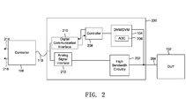
- Fig. 2 shows the components of a probe 200, which is ultimately connected to a test and measurement instrument, such as oscilloscope 108, according to some embodiments of the invention.
- the probe 200 includes two paths.
- the first path, through the DMM or DMV 104 is a high accuracy, low speed digital path.
- the second path, through high bandwidth circuitry 202, is a high bandwidth path, which provides the traditional oscilloscope measurements.
- the signal When a signal 204 is received at the probe 200, the signal is sensed by both the DMM or DMV 104 of the high accuracy digital path and the high bandwidth circuitry 202 of the high bandwidth path. Each path will be discussed in further detail below.
- the signal 204 is received and processed by the DMM or DMV 104.
- the DMM or DMV 104 consists of appropriate signal conditioning circuitry (not shown) followed by an analog-to-digital (ADC) converter 206.
- ADC analog-to-digital
- the signal 204 goes through the signal conditioning circuitry before being converted to a digital signal via ADC 206.
- the digitized measurement is then sent to controller 208.
- Controller 208 communicates with the ADC 206 as well as with a digital communication interface 210.
- the digital communication interface 210 provides the interface between the controller 208 and controller 106 through the communication link 110.
- ADC 206 sends the digitized measurement to the controller 208.
- controller 208 sends the digitized measurement to the digital communication interface 210.
- the signal 204 of the DUT 102 goes to high bandwidth circuitry 202.
- the output of the high bandwidth circuitry 202 is sent to an analog signal interface 212, which is connected to the controller 106 through the communication link 110.
- Controller 106 is connected to the oscilloscope, and the digital measurement from the high accuracy digital path or the analog signal from the high bandwidth path is output to the display of the oscilloscope.
- the oscilloscope 108 contains input buttons (not shown) to allow a user to indicated desired parameters for the digital or analog measurements that are displayed.
- Controller 106 either sends an output 214 with the digital measurement to the oscilloscope 106 and/or an output 216 with the analog measurement to the oscilloscope 106.
- the controller 106 can also scale and condition the output signal from the ranges and parameters inputted by the user at the oscilloscope.
- Probes 100-300 allow a user to use a single probe with a DUT 102 to receive digitized high accuracy measurements through the high accuracy digital path or analog measurements through the high bandwidth path. Due to the DMM or DMV 104 being placed in the probe, and controlled directly via controller 208 and indirectly via controller 106, the DMM or DMV 104 function of the probe is galvanically isolated from the oscilloscope and earth ground.
- the communication link 110 can be a conductor or, preferably, an optical fiber.
- the communication link 110 may also be a wireless or radio frequency (RF) communication link.
- An optical fiber communication link provides complete galvanic isolation to the test and measurement equipment it is connected to and ultimately from earth ground. Further, increasing the length of the optical fiber communication link 110 will allow the probe 200 to be connected to higher common-mode voltages with respect to earth ground
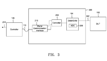
- a probe 300 may include only a high accuracy, digital path, which is galvanically isolated from controller 106 and earth ground, as shown in Fig. 3 .
- a signal 302 is measured from DUT 102
- the signal 302 is sensed by DMM or DMV 104.
- the DMM or DMV 104 has the same functions as those discussed above with respect to Fig. 2 .
- the signal 302 is processed by DMM or DMV 104 and ADC 206 to generate a digitized measurement.
- the digitized measurement is sent to the controller 208, which communicates with the digital communication interface 210.
- the digital communication interface 210 has two-way communication with the controller 208, and provides all the same functions as those discussed above with respect to the embodiment shown in Fig. 2 .
- Digital communication interface 210 is also connected to a communication link 110 and a controller 106. The output from controller 106 is sent to a test and measurement instrument, such as an oscilloscope, as discussed above with respect to Fig. 2 .
- the probes 100-300 can be any type of probe, sensor, or transducer. Although the probes discussed above are shown as a standalone devices, the probes 100-300 can be built into other devices
- the probes of the disclosed technology allow for complete galvanic isolation between the probe and the test equipment, such as an oscilloscope, connected to the probe.
- the test equipment such as an oscilloscope
- the bridging coupling across this barrier is very small which enables high common-mode rejection from direct current (DC) to very high bandwidths to be achieved.
- DC direct current
- the probes of the disclosed technology are capable of measuring signals on top of large common-mode voltages.
Landscapes
- Physics & Mathematics (AREA)
- General Physics & Mathematics (AREA)
- Measuring Instrument Details And Bridges, And Automatic Balancing Devices (AREA)
- Measurement Of Resistance Or Impedance (AREA)
- Tests Of Electronic Circuits (AREA)
Abstract
Description
- The disclosed technology relates to a probe or an accessory head for an instrument, preferably a test and measurement instrument, such as an oscilloscope, that includes a digital multimeter or a digital voltmeter that provides a reading that is galvanically isolated from earth ground.
- Digital multimeters (DMM) and digital voltmeters (DMV) are commonly used in conjunction with test and measurement instruments, probes, and accessories. The test and measurement instrument may be an oscilloscope, for example. An oscilloscope provides a visual picture in time of how a circuit is performing. Traditionally, with oscilloscopes, the accuracy and resolution of a voltage measurement is limited and is typically a ground referenced measurement. DMMs and DVMs, on the other hand, can provide extremely accurate, high resolution measurements that are galvanically isolated, also known as "floating," from earth ground.
- Past attempts have been made to incorporate DMM and DMV measurements into oscilloscopes to obtain an accurate voltage measurement. These attempts, however, have been limited by requiring an additional set of probes to be connected to the device under test or integrating the DVM feature into the oscilloscope itself that is ground referenced and is limited in sensitivity and accuracy by the traditional oscilloscope probe connected to the oscilloscope.
- Combining DMM-like and DMV-like measurement capabilities with a traditional oscilloscope voltage probe that is galvanically isolated from earth ground would overcome the limitations of the past and provide an easy to use solution. This would be particularly useful for users making non-ground referenced, or "floating," voltage measurements.
- Certain embodiments of the disclosed technology include a probe for use with a test and measurement instrument. The probe includes a digital multimeter or voltmeter with an analog-to-digital converter configured to measure a signal from a device under test and determine a digital measurement from the signal, a controller connected to the multimeter or voltmeter configured to receive the digital measurement from the multimeter or voltmeter, a digital communication interface connected to the controller configured to communicate with the controller, and a communication link connected to the digital communication interface and the analog signal interface to communicate with the test and measurement instrument.
- Certain other embodiments of the disclosed technology include a test and measurement system. The system includes a probe having a digital multimeter or voltmeter with an analog-to-digital converter configured to measure a signal from the device under test and determine a digital measurement from the signal, a controller connected to the multimeter or voltmeter configured to receive the digital measurement from the multimeter or voltmeter, a digital communication interface connected to the controller configured to communicate with the controller, and a communication link connected to the digital communication interface and an analog signal interface. The system also includes a second controller connected to the communication link and an oscilloscope connected to the probe through the second controller and the communication link.
- Certain other embodiments include a method of using a probe with an oscilloscope. The method includes measuring a signal from a device under test at the probe, determining a digital measurement from the signal with a digital multimeter or voltmeter with an analog-to-digital converter located within the probe, receiving the digital measurement by a first controller within the probe, communicating the digital measurement from the first controller to a digital communication interface within the probe, and communicating the digital measurement from the digital communication interface to a second controller through a communication link.
- The foregoing and other objects, features and advantages of the invention will become more readily apparent from the following detailed description of embodiments of the invention which proceeds with reference to the accompanying drawings.
-
-
FIG. 1 illustrates a high-level view of a test and measurement system. -
FIG. 2 illustrates a probe according to certain embodiments of the disclosed technology. -
FIG. 3 illustrates a probe according to other embodiments of the disclosed technology. - In the drawings, which are not necessarily to scale, like or corresponding elements of the disclosed systems and methods are denoted by the same reference numerals.
-
Fig. 1 shows a high level view of a test and measurement system using aprobe 100 with a DMM orDMV 104 within theprobe 100. Initially, a signal is received from a device under test (DUT) 102 by theprobe 100 and measured by DMM orDMV 104. The measurement from the DMM orDMV 104 is then sent to acontroller 106, through acommunication link 110, which will be discussed in further detail below. Finally, thecontroller 106 is connected to theoscilloscope 108 to display the measurement on a display (not shown) of theoscilloscope 108. Either a high accuracy digital measurement can be displayed on the oscilloscope or a traditional analog measurement, using a single probe. Alternately, the high accuracy measurement can be used to actively compensate the displayed analog measurement. Theprobe 100 may be eitherprobe 200 orprobe 300, discussed in further detail below. -
Fig. 2 shows the components of aprobe 200, which is ultimately connected to a test and measurement instrument, such asoscilloscope 108, according to some embodiments of the invention. As shown inFig. 2 , theprobe 200 includes two paths. The first path, through the DMM orDMV 104 is a high accuracy, low speed digital path. The second path, throughhigh bandwidth circuitry 202, is a high bandwidth path, which provides the traditional oscilloscope measurements. - When a
signal 204 is received at theprobe 200, the signal is sensed by both the DMM orDMV 104 of the high accuracy digital path and thehigh bandwidth circuitry 202 of the high bandwidth path. Each path will be discussed in further detail below. - Starting with the high accuracy path, the
signal 204 is received and processed by the DMM orDMV 104. The DMM orDMV 104 consists of appropriate signal conditioning circuitry (not shown) followed by an analog-to-digital (ADC)converter 206. Thesignal 204 goes through the signal conditioning circuitry before being converted to a digital signal via ADC 206. The digitized measurement is then sent to controller 208. -
Controller 208 communicates with the ADC 206 as well as with adigital communication interface 210. Thedigital communication interface 210 provides the interface between thecontroller 208 andcontroller 106 through thecommunication link 110. ADC 206 sends the digitized measurement to thecontroller 208. Thencontroller 208 sends the digitized measurement to thedigital communication interface 210. - Turning now to the high bandwidth path, the
signal 204 of theDUT 102 goes tohigh bandwidth circuitry 202. The output of thehigh bandwidth circuitry 202 is sent to ananalog signal interface 212, which is connected to thecontroller 106 through thecommunication link 110. -
Controller 106 is connected to the oscilloscope, and the digital measurement from the high accuracy digital path or the analog signal from the high bandwidth path is output to the display of the oscilloscope. Theoscilloscope 108, as will be readily understood by one skilled in the art, contains input buttons (not shown) to allow a user to indicated desired parameters for the digital or analog measurements that are displayed. -
Controller 106 either sends anoutput 214 with the digital measurement to theoscilloscope 106 and/or anoutput 216 with the analog measurement to theoscilloscope 106. Thecontroller 106 can also scale and condition the output signal from the ranges and parameters inputted by the user at the oscilloscope. - Probes 100-300 allow a user to use a single probe with a
DUT 102 to receive digitized high accuracy measurements through the high accuracy digital path or analog measurements through the high bandwidth path. Due to the DMM orDMV 104 being placed in the probe, and controlled directly viacontroller 208 and indirectly viacontroller 106, the DMM orDMV 104 function of the probe is galvanically isolated from the oscilloscope and earth ground. - The
communication link 110 can be a conductor or, preferably, an optical fiber. Thecommunication link 110 may also be a wireless or radio frequency (RF) communication link. An optical fiber communication link provides complete galvanic isolation to the test and measurement equipment it is connected to and ultimately from earth ground. Further, increasing the length of the opticalfiber communication link 110 will allow theprobe 200 to be connected to higher common-mode voltages with respect to earth ground - In other embodiments, a
probe 300 may include only a high accuracy, digital path, which is galvanically isolated fromcontroller 106 and earth ground, as shown inFig. 3 . For example, inFig. 3 , when asignal 302 is measured fromDUT 102, thesignal 302 is sensed by DMM orDMV 104. The DMM orDMV 104 has the same functions as those discussed above with respect toFig. 2 . For example, when thesignal 302 is sensed by DMM orDMV 104, thesignal 302 is processed by DMM orDMV 104 andADC 206 to generate a digitized measurement. The digitized measurement is sent to thecontroller 208, which communicates with thedigital communication interface 210. - As in the embodiment shown in
Fig. 2 , thedigital communication interface 210 has two-way communication with thecontroller 208, and provides all the same functions as those discussed above with respect to the embodiment shown inFig. 2 .Digital communication interface 210 is also connected to acommunication link 110 and acontroller 106. The output fromcontroller 106 is sent to a test and measurement instrument, such as an oscilloscope, as discussed above with respect toFig. 2 . - As will be readily understood by one skilled in the art, the probes 100-300 can be any type of probe, sensor, or transducer. Although the probes discussed above are shown as a standalone devices, the probes 100-300 can be built into other devices
- The probes of the disclosed technology allow for complete galvanic isolation between the probe and the test equipment, such as an oscilloscope, connected to the probe. When a fiber optic communication link is used for an isolation barrier, the bridging coupling across this barrier is very small which enables high common-mode rejection from direct current (DC) to very high bandwidths to be achieved. This allows the user to make non-ground referenced measurements and eliminates the potential for circulating currents to develop forming "ground-loops" which degrade the accuracy and signal fidelity of the measurement. The probes of the disclosed technology are capable of measuring signals on top of large common-mode voltages.
- Having described and illustrated the principles of the disclosed technology in a preferred embodiment thereof, it should be apparent that the disclosed technology can be modified in arrangement and detail without departing from such principles. We claim all modifications and variations coming within the scope of the following claims.
Claims (12)
- A probe for use with a test and measurement instrument, comprising:a digital multimeter or voltmeter (109) with an analog-to-digital converter (206) configured to receive a signal from a device under test and determine a digital measurement from the signal;a controller (208) connected to the multimeter or voltmeter configured to receive the digital measurement from the multimeter or voltmeter;a digital communication interface (210) connected to the controller configured to communicate with the controller; anda communication link (210) connected to the digital communication interface and the analog signal interface to communicate with the test and measurement instrument.
- The probe of claim 1, further comprising:high bandwidth circuitry (202) connected to the device under test configured to receive a signal from a device under test and process the signal from the device under test; andan analog signal interface (212) connected to the high bandwidth circuitry and the communication link.
- The probe of claim 1 or 2, wherein the communication link is an optical fiber, a conductor, a wireless communication link or a radio frequency communication link.
- The probe of claim 1 or 2, wherein the communication link is an optical fiber.
- The probe of any preceding claim, wherein the controller and the communication link have two-way communication.
- The probe of any preceding claim, wherein the probe is a sensor or transducer.
- A test and measurement system, including a probe according to any of claims 1-6, and further including:a second controller (106) connected to the communication link; andan oscilloscope (108) connected to the probe through the second controller and the communication link.
- The test and measurement system of claim 7, wherein the second controller (106) communicates with the digital communication interface (210) to receive the digital measurement and the analog signal interface (212) to receive an analog signal from the high bandwidth circuitry (202).
- A method of using a probe with a test and measurement instrument, comprising:measuring a signal from a device under test at the probe;determining a digital measurement from the signal with a digital multimeter or voltmeter with an analog-to-digital converter located within the probe;receiving the digital measurement by a first controller within the probe;communicating the digital measurement from the first controller to a digital communication interface within the probe; andcommunicating the digital measurement from the digital communication interface to a second controller through a communication link.
- The method of claim 9, further comprising:measuring the signal from a device under test and processing the signal from the device under test by high bandwidth circuitry within the probe; andreceiving the processed output at an analog signal interface within the probe.
- The method of claim 9 or 10, further comprising:sending the digital measurement or the processed output to the test and measurement instrument through a communication link and the second controller; anddisplaying the digital measurement or the processed output on a display of the test and measurement instrument.
- The method of claim 11, wherein the communication link is an optical fiber, a conductor, a wireless communication link or a radio frequency communication link.
Applications Claiming Priority (2)
| Application Number | Priority Date | Filing Date | Title |
|---|---|---|---|
| US201361868968P | 2013-08-22 | 2013-08-22 | |
| US14/061,327 US9625495B2 (en) | 2013-08-22 | 2013-10-23 | Isolated probe with digital multimeter or digital voltmeter |
Publications (2)
| Publication Number | Publication Date |
|---|---|
| EP2843423A1 true EP2843423A1 (en) | 2015-03-04 |
| EP2843423B1 EP2843423B1 (en) | 2022-07-06 |
Family
ID=51494075
Family Applications (1)
| Application Number | Title | Priority Date | Filing Date |
|---|---|---|---|
| EP14181935.9A Active EP2843423B1 (en) | 2013-08-22 | 2014-08-22 | Isolated probe with digital multimeter or digital voltmeter |
Country Status (4)
| Country | Link |
|---|---|
| US (1) | US9625495B2 (en) |
| EP (1) | EP2843423B1 (en) |
| JP (1) | JP6714317B2 (en) |
| CN (1) | CN104422798B (en) |
Cited By (1)
| Publication number | Priority date | Publication date | Assignee | Title |
|---|---|---|---|---|
| US10886588B2 (en) | 2018-09-26 | 2021-01-05 | Keysight Technologies, Inc. | High dynamic range probe using pole-zero cancellation |
Families Citing this family (15)
| Publication number | Priority date | Publication date | Assignee | Title |
|---|---|---|---|---|
| US10602082B2 (en) | 2014-09-17 | 2020-03-24 | Fluke Corporation | Triggered operation and/or recording of test and measurement or imaging tools |
| US9568368B2 (en) * | 2014-09-17 | 2017-02-14 | Fluke Corporation | Mobile device used with isolated test and measurement input block |
| WO2016065261A1 (en) | 2014-10-24 | 2016-04-28 | Fluke Corporation | Imaging system employing fixed, modular mobile, and portable infrared cameras with ability to receive, communicate, and display data and images with proximity detection |
| US10067165B2 (en) | 2015-09-04 | 2018-09-04 | Ford Global Technologies, Llc | Isolated differential voltage probe for EMI noise source |
| US20170078544A1 (en) | 2015-09-16 | 2017-03-16 | Fluke Corporation | Electrical isolation for a camera in a test and measurement tool |
| WO2017070629A1 (en) | 2015-10-23 | 2017-04-27 | Fluke Corporation | Imaging tool for vibration and/or misalignment analysis |
| US10656181B2 (en) * | 2016-04-05 | 2020-05-19 | Keithley Instruments, Llc | Rejection of mechanical vibration induced noise in electrical measurements |
| CN106646188A (en) * | 2016-10-26 | 2017-05-10 | 乐视控股(北京)有限公司 | Sleeve structure, terminal, measurement instrument, and measurement instrument control method , device and equipment |
| US11300588B2 (en) * | 2017-04-21 | 2022-04-12 | Rohde & Schwarz Gmbh & Co. Kg | Adapter for a current probe and testing system |
| EP3404427B1 (en) | 2017-05-18 | 2024-11-13 | Rohde & Schwarz GmbH & Co. KG | Electrical test and measurement device, measurement extension device as well as test and measurement system |
| WO2019014622A1 (en) | 2017-07-14 | 2019-01-17 | Tektronix, Inc. | Systems, devices, and methods for measuring direct current/low frequency signal components |
| EP3540446B1 (en) * | 2018-03-13 | 2021-09-29 | Rohde & Schwarz GmbH & Co. KG | Measurement system and method for operating a measurement system |
| CN110703736A (en) * | 2019-10-24 | 2020-01-17 | 深圳市道通科技股份有限公司 | A vehicle diagnostic equipment, system and method |
| US12339298B2 (en) * | 2021-12-29 | 2025-06-24 | Tektronix, Inc. | Method of CTLE estimation using channel step-response for transmitter link equalization test |
| US12181497B2 (en) | 2022-11-23 | 2024-12-31 | Rohde & Schwarz Gmbh & Co. Kg | Voltage measurement and/or overvoltage protection circuit for a measurement instrument |
Citations (9)
| Publication number | Priority date | Publication date | Assignee | Title |
|---|---|---|---|---|
| US4034291A (en) * | 1975-04-14 | 1977-07-05 | Tektronix, Inc. | Electronic measuring instrument combining an oscilloscope and a digital multimeter |
| US4758779A (en) * | 1986-04-07 | 1988-07-19 | Tektronix, Inc. | Probe body for an electrical measurement system |
| US5034698A (en) * | 1990-01-22 | 1991-07-23 | Hiro Moriyasu | Dual-path wideband and precision data acquisition system |
| US5225776A (en) * | 1991-10-07 | 1993-07-06 | Tektronix, Inc. | Method and apparatus for probing and sampling an electrical signal |
| WO2004049897A2 (en) * | 2002-12-03 | 2004-06-17 | Tecnomotor Eletronica Do Brasil Ltda. | Portable body for diagnostic equipment |
| US20070069716A1 (en) * | 2003-09-01 | 2007-03-29 | Elan Digital Systems Limited | Digital multi-meter |
| US20080042666A1 (en) * | 2006-08-16 | 2008-02-21 | Sullivan Steven K | Multiple probe acquisition system |
| US20100277190A1 (en) * | 2007-12-04 | 2010-11-04 | Rohde & Schwarz Gmbh & Co. Kg | Probe with high-precision dc-voltage measurement |
| US20120046897A1 (en) * | 2010-08-18 | 2012-02-23 | Snap-On Incorporated | System and method for simultaneous display of waveforms generated from input signals received at a data acquisition device |
Family Cites Families (14)
| Publication number | Priority date | Publication date | Assignee | Title |
|---|---|---|---|---|
| JPS5437787A (en) * | 1977-08-31 | 1979-03-20 | Iwatsu Electric Co Ltd | Waveform comparative display method using crt |
| CH672840A5 (en) * | 1986-10-13 | 1989-12-29 | Svaetopluk Radakovic | |
| US5396168A (en) * | 1992-03-27 | 1995-03-07 | Tandy Corporation | Digital multimeter with microprocessor control |
| JPH0815317A (en) * | 1994-06-29 | 1996-01-19 | Sony Tektronix Corp | Wireless probe |
| JPH1151974A (en) * | 1997-07-31 | 1999-02-26 | Nec Home Electron Ltd | Probe adapter |
| US20040093342A1 (en) * | 2001-06-27 | 2004-05-13 | Ronald Arbo | Universal data mapping system |
| JP2006333257A (en) * | 2005-05-27 | 2006-12-07 | Kddi Corp | Noise removal method and apparatus |
| CN201368887Y (en) * | 2009-03-16 | 2009-12-23 | 北京京东方光电科技有限公司 | Test probe for collecting test signal |
| JP5839989B2 (en) * | 2011-01-14 | 2016-01-06 | 日置電機株式会社 | Measuring system |
| JP5724575B2 (en) * | 2011-04-20 | 2015-05-27 | 株式会社セガ | GAME PROGRAM, GAME SYSTEM, GAME DEVICE, AND STORAGE MEDIUM |
| JP5858651B2 (en) * | 2011-06-08 | 2016-02-10 | キヤノン株式会社 | Information processing apparatus, control method thereof, and control program |
| US20130106401A1 (en) * | 2011-10-31 | 2013-05-02 | Agilent Technologies, Inc. | Oscilloscope probe comprising status indicator |
| CN202975070U (en) * | 2012-12-12 | 2013-06-05 | 广州德肯电子有限公司 | Probe of oscilloscope |
| CN202975071U (en) * | 2012-12-12 | 2013-06-05 | 广州德肯电子有限公司 | Wireless active probe of oscilloscope |
-
2013
- 2013-10-23 US US14/061,327 patent/US9625495B2/en active Active
-
2014
- 2014-08-18 JP JP2014165958A patent/JP6714317B2/en active Active
- 2014-08-22 EP EP14181935.9A patent/EP2843423B1/en active Active
- 2014-08-22 CN CN201410417595.0A patent/CN104422798B/en active Active
Patent Citations (9)
| Publication number | Priority date | Publication date | Assignee | Title |
|---|---|---|---|---|
| US4034291A (en) * | 1975-04-14 | 1977-07-05 | Tektronix, Inc. | Electronic measuring instrument combining an oscilloscope and a digital multimeter |
| US4758779A (en) * | 1986-04-07 | 1988-07-19 | Tektronix, Inc. | Probe body for an electrical measurement system |
| US5034698A (en) * | 1990-01-22 | 1991-07-23 | Hiro Moriyasu | Dual-path wideband and precision data acquisition system |
| US5225776A (en) * | 1991-10-07 | 1993-07-06 | Tektronix, Inc. | Method and apparatus for probing and sampling an electrical signal |
| WO2004049897A2 (en) * | 2002-12-03 | 2004-06-17 | Tecnomotor Eletronica Do Brasil Ltda. | Portable body for diagnostic equipment |
| US20070069716A1 (en) * | 2003-09-01 | 2007-03-29 | Elan Digital Systems Limited | Digital multi-meter |
| US20080042666A1 (en) * | 2006-08-16 | 2008-02-21 | Sullivan Steven K | Multiple probe acquisition system |
| US20100277190A1 (en) * | 2007-12-04 | 2010-11-04 | Rohde & Schwarz Gmbh & Co. Kg | Probe with high-precision dc-voltage measurement |
| US20120046897A1 (en) * | 2010-08-18 | 2012-02-23 | Snap-On Incorporated | System and method for simultaneous display of waveforms generated from input signals received at a data acquisition device |
Cited By (1)
| Publication number | Priority date | Publication date | Assignee | Title |
|---|---|---|---|---|
| US10886588B2 (en) | 2018-09-26 | 2021-01-05 | Keysight Technologies, Inc. | High dynamic range probe using pole-zero cancellation |
Also Published As
| Publication number | Publication date |
|---|---|
| US9625495B2 (en) | 2017-04-18 |
| EP2843423B1 (en) | 2022-07-06 |
| CN104422798B (en) | 2018-11-09 |
| CN104422798A (en) | 2015-03-18 |
| JP6714317B2 (en) | 2020-06-24 |
| JP2015040858A (en) | 2015-03-02 |
| US20150054492A1 (en) | 2015-02-26 |
Similar Documents
| Publication | Publication Date | Title |
|---|---|---|
| US9625495B2 (en) | Isolated probe with digital multimeter or digital voltmeter | |
| US8845870B2 (en) | Digital potentiostat circuit and system | |
| CN109765429B (en) | Impedance measuring system and impedance measuring method | |
| EP2913684B1 (en) | Dynamic compensation circuit | |
| CN210346590U (en) | Wireless static strain tester and wireless static strain test system | |
| CN209417154U (en) | Resistance measuring circuit and resistivity-measuring devices | |
| CN105823917B (en) | Method for simultaneously monitoring current, temperature, voltage and current and dual-mode instrument | |
| CN103703380A (en) | Differential voltage measurement | |
| KR102691270B1 (en) | Systems, devices, and methods for measuring direct current/low frequency signal components | |
| Pouryazdan et al. | Non-contact long range AC voltage measurement | |
| US20060113984A1 (en) | Phase identification system and method | |
| CN111044963B (en) | High-frequency current sensor calibration method and device adopting coaxial shunt | |
| CN107727906B (en) | A method for automatic setting of an oscilloscope and its device | |
| US4697151A (en) | Method and apparatus for testing operational amplifier leakage current | |
| US20160041208A1 (en) | High voltage digital voltmeter and wireless phaser | |
| US3283242A (en) | Impedance meter having signal leveling apparatus | |
| US11619666B1 (en) | Source measure apparatus including feedback path and measurement path | |
| US2481492A (en) | Intensity, intensity ratio, and phase difference measuring system for geophysical prospecting | |
| CN117031100B (en) | A front-end circuit of a multimeter and the multimeter itself. | |
| CN219574243U (en) | High-resistance fault loop resistance precision measurement circuit for railway signal cable | |
| Houtzager et al. | Development of a wide-range sampling impedance ratio bridge | |
| CN219935963U (en) | Voltage and current measurement channel of digital bridge and digital bridge | |
| CN117761485B (en) | An impedance testing device and method | |
| US9804204B2 (en) | Method of implementation of peak hold in a phasing voltmeter | |
| Cirstea et al. | An inductive system for measuring microampere currents |
Legal Events
| Date | Code | Title | Description |
|---|---|---|---|
| 17P | Request for examination filed |
Effective date: 20140822 |
|
| AK | Designated contracting states |
Kind code of ref document: A1 Designated state(s): AL AT BE BG CH CY CZ DE DK EE ES FI FR GB GR HR HU IE IS IT LI LT LU LV MC MK MT NL NO PL PT RO RS SE SI SK SM TR |
|
| AX | Request for extension of the european patent |
Extension state: BA ME |
|
| PUAI | Public reference made under article 153(3) epc to a published international application that has entered the european phase |
Free format text: ORIGINAL CODE: 0009012 |
|
| R17P | Request for examination filed (corrected) |
Effective date: 20150827 |
|
| RBV | Designated contracting states (corrected) |
Designated state(s): AL AT BE BG CH CY CZ DE DK EE ES FI FR GB GR HR HU IE IS IT LI LT LU LV MC MK MT NL NO PL PT RO RS SE SI SK SM TR |
|
| STAA | Information on the status of an ep patent application or granted ep patent |
Free format text: STATUS: EXAMINATION IS IN PROGRESS |
|
| 17Q | First examination report despatched |
Effective date: 20190912 |
|
| GRAP | Despatch of communication of intention to grant a patent |
Free format text: ORIGINAL CODE: EPIDOSNIGR1 |
|
| STAA | Information on the status of an ep patent application or granted ep patent |
Free format text: STATUS: GRANT OF PATENT IS INTENDED |
|
| INTG | Intention to grant announced |
Effective date: 20220120 |
|
| GRAS | Grant fee paid |
Free format text: ORIGINAL CODE: EPIDOSNIGR3 |
|
| GRAA | (expected) grant |
Free format text: ORIGINAL CODE: 0009210 |
|
| STAA | Information on the status of an ep patent application or granted ep patent |
Free format text: STATUS: THE PATENT HAS BEEN GRANTED |
|
| AK | Designated contracting states |
Kind code of ref document: B1 Designated state(s): AL AT BE BG CH CY CZ DE DK EE ES FI FR GB GR HR HU IE IS IT LI LT LU LV MC MK MT NL NO PL PT RO RS SE SI SK SM TR |
|
| REG | Reference to a national code |
Ref country code: GB Ref legal event code: FG4D |
|
| REG | Reference to a national code |
Ref country code: AT Ref legal event code: REF Ref document number: 1503227 Country of ref document: AT Kind code of ref document: T Effective date: 20220715 Ref country code: CH Ref legal event code: EP |
|
| REG | Reference to a national code |
Ref country code: DE Ref legal event code: R096 Ref document number: 602014084209 Country of ref document: DE |
|
| REG | Reference to a national code |
Ref country code: IE Ref legal event code: FG4D |
|
| REG | Reference to a national code |
Ref country code: LT Ref legal event code: MG9D |
|
| REG | Reference to a national code |
Ref country code: NL Ref legal event code: MP Effective date: 20220706 |
|
| PG25 | Lapsed in a contracting state [announced via postgrant information from national office to epo] |
Ref country code: SE Free format text: LAPSE BECAUSE OF FAILURE TO SUBMIT A TRANSLATION OF THE DESCRIPTION OR TO PAY THE FEE WITHIN THE PRESCRIBED TIME-LIMIT Effective date: 20220706 Ref country code: RS Free format text: LAPSE BECAUSE OF FAILURE TO SUBMIT A TRANSLATION OF THE DESCRIPTION OR TO PAY THE FEE WITHIN THE PRESCRIBED TIME-LIMIT Effective date: 20220706 Ref country code: PT Free format text: LAPSE BECAUSE OF FAILURE TO SUBMIT A TRANSLATION OF THE DESCRIPTION OR TO PAY THE FEE WITHIN THE PRESCRIBED TIME-LIMIT Effective date: 20221107 Ref country code: NO Free format text: LAPSE BECAUSE OF FAILURE TO SUBMIT A TRANSLATION OF THE DESCRIPTION OR TO PAY THE FEE WITHIN THE PRESCRIBED TIME-LIMIT Effective date: 20221006 Ref country code: NL Free format text: LAPSE BECAUSE OF FAILURE TO SUBMIT A TRANSLATION OF THE DESCRIPTION OR TO PAY THE FEE WITHIN THE PRESCRIBED TIME-LIMIT Effective date: 20220706 Ref country code: LV Free format text: LAPSE BECAUSE OF FAILURE TO SUBMIT A TRANSLATION OF THE DESCRIPTION OR TO PAY THE FEE WITHIN THE PRESCRIBED TIME-LIMIT Effective date: 20220706 Ref country code: LT Free format text: LAPSE BECAUSE OF FAILURE TO SUBMIT A TRANSLATION OF THE DESCRIPTION OR TO PAY THE FEE WITHIN THE PRESCRIBED TIME-LIMIT Effective date: 20220706 Ref country code: FI Free format text: LAPSE BECAUSE OF FAILURE TO SUBMIT A TRANSLATION OF THE DESCRIPTION OR TO PAY THE FEE WITHIN THE PRESCRIBED TIME-LIMIT Effective date: 20220706 Ref country code: ES Free format text: LAPSE BECAUSE OF FAILURE TO SUBMIT A TRANSLATION OF THE DESCRIPTION OR TO PAY THE FEE WITHIN THE PRESCRIBED TIME-LIMIT Effective date: 20220706 |
|
| REG | Reference to a national code |
Ref country code: AT Ref legal event code: MK05 Ref document number: 1503227 Country of ref document: AT Kind code of ref document: T Effective date: 20220706 |
|
| PG25 | Lapsed in a contracting state [announced via postgrant information from national office to epo] |
Ref country code: PL Free format text: LAPSE BECAUSE OF FAILURE TO SUBMIT A TRANSLATION OF THE DESCRIPTION OR TO PAY THE FEE WITHIN THE PRESCRIBED TIME-LIMIT Effective date: 20220706 Ref country code: IS Free format text: LAPSE BECAUSE OF FAILURE TO SUBMIT A TRANSLATION OF THE DESCRIPTION OR TO PAY THE FEE WITHIN THE PRESCRIBED TIME-LIMIT Effective date: 20221106 Ref country code: HR Free format text: LAPSE BECAUSE OF FAILURE TO SUBMIT A TRANSLATION OF THE DESCRIPTION OR TO PAY THE FEE WITHIN THE PRESCRIBED TIME-LIMIT Effective date: 20220706 Ref country code: GR Free format text: LAPSE BECAUSE OF FAILURE TO SUBMIT A TRANSLATION OF THE DESCRIPTION OR TO PAY THE FEE WITHIN THE PRESCRIBED TIME-LIMIT Effective date: 20221007 |
|
| REG | Reference to a national code |
Ref country code: CH Ref legal event code: PL |
|
| REG | Reference to a national code |
Ref country code: DE Ref legal event code: R097 Ref document number: 602014084209 Country of ref document: DE |
|
| PG25 | Lapsed in a contracting state [announced via postgrant information from national office to epo] |
Ref country code: SM Free format text: LAPSE BECAUSE OF FAILURE TO SUBMIT A TRANSLATION OF THE DESCRIPTION OR TO PAY THE FEE WITHIN THE PRESCRIBED TIME-LIMIT Effective date: 20220706 Ref country code: RO Free format text: LAPSE BECAUSE OF FAILURE TO SUBMIT A TRANSLATION OF THE DESCRIPTION OR TO PAY THE FEE WITHIN THE PRESCRIBED TIME-LIMIT Effective date: 20220706 Ref country code: MC Free format text: LAPSE BECAUSE OF FAILURE TO SUBMIT A TRANSLATION OF THE DESCRIPTION OR TO PAY THE FEE WITHIN THE PRESCRIBED TIME-LIMIT Effective date: 20220706 Ref country code: LU Free format text: LAPSE BECAUSE OF NON-PAYMENT OF DUE FEES Effective date: 20220822 Ref country code: LI Free format text: LAPSE BECAUSE OF NON-PAYMENT OF DUE FEES Effective date: 20220831 Ref country code: DK Free format text: LAPSE BECAUSE OF FAILURE TO SUBMIT A TRANSLATION OF THE DESCRIPTION OR TO PAY THE FEE WITHIN THE PRESCRIBED TIME-LIMIT Effective date: 20220706 Ref country code: CZ Free format text: LAPSE BECAUSE OF FAILURE TO SUBMIT A TRANSLATION OF THE DESCRIPTION OR TO PAY THE FEE WITHIN THE PRESCRIBED TIME-LIMIT Effective date: 20220706 Ref country code: CH Free format text: LAPSE BECAUSE OF NON-PAYMENT OF DUE FEES Effective date: 20220831 Ref country code: AT Free format text: LAPSE BECAUSE OF FAILURE TO SUBMIT A TRANSLATION OF THE DESCRIPTION OR TO PAY THE FEE WITHIN THE PRESCRIBED TIME-LIMIT Effective date: 20220706 |
|
| REG | Reference to a national code |
Ref country code: BE Ref legal event code: MM Effective date: 20220831 |
|
| PLBE | No opposition filed within time limit |
Free format text: ORIGINAL CODE: 0009261 |
|
| STAA | Information on the status of an ep patent application or granted ep patent |
Free format text: STATUS: NO OPPOSITION FILED WITHIN TIME LIMIT |
|
| PG25 | Lapsed in a contracting state [announced via postgrant information from national office to epo] |
Ref country code: SK Free format text: LAPSE BECAUSE OF FAILURE TO SUBMIT A TRANSLATION OF THE DESCRIPTION OR TO PAY THE FEE WITHIN THE PRESCRIBED TIME-LIMIT Effective date: 20220706 Ref country code: EE Free format text: LAPSE BECAUSE OF FAILURE TO SUBMIT A TRANSLATION OF THE DESCRIPTION OR TO PAY THE FEE WITHIN THE PRESCRIBED TIME-LIMIT Effective date: 20220706 |
|
| 26N | No opposition filed |
Effective date: 20230411 |
|
| GBPC | Gb: european patent ceased through non-payment of renewal fee |
Effective date: 20221006 |
|
| PG25 | Lapsed in a contracting state [announced via postgrant information from national office to epo] |
Ref country code: AL Free format text: LAPSE BECAUSE OF FAILURE TO SUBMIT A TRANSLATION OF THE DESCRIPTION OR TO PAY THE FEE WITHIN THE PRESCRIBED TIME-LIMIT Effective date: 20220706 |
|
| P01 | Opt-out of the competence of the unified patent court (upc) registered |
Effective date: 20230530 |
|
| PG25 | Lapsed in a contracting state [announced via postgrant information from national office to epo] |
Ref country code: IE Free format text: LAPSE BECAUSE OF NON-PAYMENT OF DUE FEES Effective date: 20220822 Ref country code: FR Free format text: LAPSE BECAUSE OF NON-PAYMENT OF DUE FEES Effective date: 20220906 |
|
| PG25 | Lapsed in a contracting state [announced via postgrant information from national office to epo] |
Ref country code: SI Free format text: LAPSE BECAUSE OF FAILURE TO SUBMIT A TRANSLATION OF THE DESCRIPTION OR TO PAY THE FEE WITHIN THE PRESCRIBED TIME-LIMIT Effective date: 20220706 |
|
| PG25 | Lapsed in a contracting state [announced via postgrant information from national office to epo] |
Ref country code: BE Free format text: LAPSE BECAUSE OF NON-PAYMENT OF DUE FEES Effective date: 20220831 |
|
| PG25 | Lapsed in a contracting state [announced via postgrant information from national office to epo] |
Ref country code: GB Free format text: LAPSE BECAUSE OF NON-PAYMENT OF DUE FEES Effective date: 20221006 |
|
| PG25 | Lapsed in a contracting state [announced via postgrant information from national office to epo] |
Ref country code: IT Free format text: LAPSE BECAUSE OF FAILURE TO SUBMIT A TRANSLATION OF THE DESCRIPTION OR TO PAY THE FEE WITHIN THE PRESCRIBED TIME-LIMIT Effective date: 20220706 |
|
| PG25 | Lapsed in a contracting state [announced via postgrant information from national office to epo] |
Ref country code: HU Free format text: LAPSE BECAUSE OF FAILURE TO SUBMIT A TRANSLATION OF THE DESCRIPTION OR TO PAY THE FEE WITHIN THE PRESCRIBED TIME-LIMIT; INVALID AB INITIO Effective date: 20140822 |
|
| PG25 | Lapsed in a contracting state [announced via postgrant information from national office to epo] |
Ref country code: CY Free format text: LAPSE BECAUSE OF FAILURE TO SUBMIT A TRANSLATION OF THE DESCRIPTION OR TO PAY THE FEE WITHIN THE PRESCRIBED TIME-LIMIT Effective date: 20220706 |
|
| PG25 | Lapsed in a contracting state [announced via postgrant information from national office to epo] |
Ref country code: MK Free format text: LAPSE BECAUSE OF FAILURE TO SUBMIT A TRANSLATION OF THE DESCRIPTION OR TO PAY THE FEE WITHIN THE PRESCRIBED TIME-LIMIT Effective date: 20220706 |
|
| PG25 | Lapsed in a contracting state [announced via postgrant information from national office to epo] |
Ref country code: TR Free format text: LAPSE BECAUSE OF FAILURE TO SUBMIT A TRANSLATION OF THE DESCRIPTION OR TO PAY THE FEE WITHIN THE PRESCRIBED TIME-LIMIT Effective date: 20220706 |
|
| PG25 | Lapsed in a contracting state [announced via postgrant information from national office to epo] |
Ref country code: BG Free format text: LAPSE BECAUSE OF FAILURE TO SUBMIT A TRANSLATION OF THE DESCRIPTION OR TO PAY THE FEE WITHIN THE PRESCRIBED TIME-LIMIT Effective date: 20220706 |
|
| PG25 | Lapsed in a contracting state [announced via postgrant information from national office to epo] |
Ref country code: MT Free format text: LAPSE BECAUSE OF FAILURE TO SUBMIT A TRANSLATION OF THE DESCRIPTION OR TO PAY THE FEE WITHIN THE PRESCRIBED TIME-LIMIT Effective date: 20220706 |
|
| PGFP | Annual fee paid to national office [announced via postgrant information from national office to epo] |
Ref country code: DE Payment date: 20250827 Year of fee payment: 12 |