EP2843358A1 - Magnet device and position sensing system - Google Patents
Magnet device and position sensing system Download PDFInfo
- Publication number
- EP2843358A1 EP2843358A1 EP13778969.9A EP13778969A EP2843358A1 EP 2843358 A1 EP2843358 A1 EP 2843358A1 EP 13778969 A EP13778969 A EP 13778969A EP 2843358 A1 EP2843358 A1 EP 2843358A1
- Authority
- EP
- European Patent Office
- Prior art keywords
- magnet
- flux density
- magnetic flux
- magnet member
- rotatable shaft
- Prior art date
- Legal status (The legal status is an assumption and is not a legal conclusion. Google has not performed a legal analysis and makes no representation as to the accuracy of the status listed.)
- Ceased
Links
Images






Classifications
-
- G—PHYSICS
- G01—MEASURING; TESTING
- G01B—MEASURING LENGTH, THICKNESS OR SIMILAR LINEAR DIMENSIONS; MEASURING ANGLES; MEASURING AREAS; MEASURING IRREGULARITIES OF SURFACES OR CONTOURS
- G01B7/00—Measuring arrangements characterised by the use of electric or magnetic techniques
- G01B7/30—Measuring arrangements characterised by the use of electric or magnetic techniques for measuring angles or tapers; for testing the alignment of axes
-
- G—PHYSICS
- G01—MEASURING; TESTING
- G01D—MEASURING NOT SPECIALLY ADAPTED FOR A SPECIFIC VARIABLE; ARRANGEMENTS FOR MEASURING TWO OR MORE VARIABLES NOT COVERED IN A SINGLE OTHER SUBCLASS; TARIFF METERING APPARATUS; MEASURING OR TESTING NOT OTHERWISE PROVIDED FOR
- G01D5/00—Mechanical means for transferring the output of a sensing member; Means for converting the output of a sensing member to another variable where the form or nature of the sensing member does not constrain the means for converting; Transducers not specially adapted for a specific variable
- G01D5/12—Mechanical means for transferring the output of a sensing member; Means for converting the output of a sensing member to another variable where the form or nature of the sensing member does not constrain the means for converting; Transducers not specially adapted for a specific variable using electric or magnetic means
- G01D5/14—Mechanical means for transferring the output of a sensing member; Means for converting the output of a sensing member to another variable where the form or nature of the sensing member does not constrain the means for converting; Transducers not specially adapted for a specific variable using electric or magnetic means influencing the magnitude of a current or voltage
- G01D5/142—Mechanical means for transferring the output of a sensing member; Means for converting the output of a sensing member to another variable where the form or nature of the sensing member does not constrain the means for converting; Transducers not specially adapted for a specific variable using electric or magnetic means influencing the magnitude of a current or voltage using Hall-effect devices
- G01D5/145—Mechanical means for transferring the output of a sensing member; Means for converting the output of a sensing member to another variable where the form or nature of the sensing member does not constrain the means for converting; Transducers not specially adapted for a specific variable using electric or magnetic means influencing the magnitude of a current or voltage using Hall-effect devices influenced by the relative movement between the Hall device and magnetic fields
-
- H—ELECTRICITY
- H01—ELECTRIC ELEMENTS
- H01F—MAGNETS; INDUCTANCES; TRANSFORMERS; SELECTION OF MATERIALS FOR THEIR MAGNETIC PROPERTIES
- H01F7/00—Magnets
- H01F7/02—Permanent magnets [PM]
- H01F7/0205—Magnetic circuits with PM in general
-
- G—PHYSICS
- G01—MEASURING; TESTING
- G01B—MEASURING LENGTH, THICKNESS OR SIMILAR LINEAR DIMENSIONS; MEASURING ANGLES; MEASURING AREAS; MEASURING IRREGULARITIES OF SURFACES OR CONTOURS
- G01B7/00—Measuring arrangements characterised by the use of electric or magnetic techniques
- G01B7/003—Measuring arrangements characterised by the use of electric or magnetic techniques for measuring position, not involving coordinate determination
-
- G—PHYSICS
- G01—MEASURING; TESTING
- G01D—MEASURING NOT SPECIALLY ADAPTED FOR A SPECIFIC VARIABLE; ARRANGEMENTS FOR MEASURING TWO OR MORE VARIABLES NOT COVERED IN A SINGLE OTHER SUBCLASS; TARIFF METERING APPARATUS; MEASURING OR TESTING NOT OTHERWISE PROVIDED FOR
- G01D2205/00—Indexing scheme relating to details of means for transferring or converting the output of a sensing member
- G01D2205/40—Position sensors comprising arrangements for concentrating or redirecting magnetic flux
-
- G—PHYSICS
- G01—MEASURING; TESTING
- G01D—MEASURING NOT SPECIALLY ADAPTED FOR A SPECIFIC VARIABLE; ARRANGEMENTS FOR MEASURING TWO OR MORE VARIABLES NOT COVERED IN A SINGLE OTHER SUBCLASS; TARIFF METERING APPARATUS; MEASURING OR TESTING NOT OTHERWISE PROVIDED FOR
- G01D5/00—Mechanical means for transferring the output of a sensing member; Means for converting the output of a sensing member to another variable where the form or nature of the sensing member does not constrain the means for converting; Transducers not specially adapted for a specific variable
- G01D5/12—Mechanical means for transferring the output of a sensing member; Means for converting the output of a sensing member to another variable where the form or nature of the sensing member does not constrain the means for converting; Transducers not specially adapted for a specific variable using electric or magnetic means
- G01D5/14—Mechanical means for transferring the output of a sensing member; Means for converting the output of a sensing member to another variable where the form or nature of the sensing member does not constrain the means for converting; Transducers not specially adapted for a specific variable using electric or magnetic means influencing the magnitude of a current or voltage
- G01D5/142—Mechanical means for transferring the output of a sensing member; Means for converting the output of a sensing member to another variable where the form or nature of the sensing member does not constrain the means for converting; Transducers not specially adapted for a specific variable using electric or magnetic means influencing the magnitude of a current or voltage using Hall-effect devices
- G01D5/147—Mechanical means for transferring the output of a sensing member; Means for converting the output of a sensing member to another variable where the form or nature of the sensing member does not constrain the means for converting; Transducers not specially adapted for a specific variable using electric or magnetic means influencing the magnitude of a current or voltage using Hall-effect devices influenced by the movement of a third element, the position of Hall device and the source of magnetic field being fixed in respect to each other
Definitions
- the present disclosure relates generally to a magnet device and a position sensing device, and in particular, to a magnet device that is used in a position sensing device for detecting an angular position range of a rotatable shaft.
- mechanical-contacted position sensing devices are used to detect angular positions of a rotatable shaft.
- mechanical-contacted position sensing devices have some shortcomings including mechanical wear, low angle accuracy and reliability and no diagnostic capability.
- the electronic sensing system includes a sensing device for generating analog electrical signals in response to the rotation of the rotatable shaft and the electronic sensing system further processes the analog signals to generate the binary signals to indicate the angular position of the rotatable shaft.
- a magnet device is attached on the rotatable shaft and adapted to rotate together with the rotatable shaft. The magnet device causes magnetic flux density changes/magnetic field changes to the sensing device while it is rotating around the rotatable shaft.
- the sensing device generates analog electrical signals in response to the magnetic flux density changes/magnetic field changes and the analog electric signals are then converted into binary signals.
- the present disclosure provides a magnet device for providing the magnetic density changes/magnetic field changes in relation to a detecting position, which comprises:
- the magnet device is use with a sensing device, which has the detecting position where a sensing element is located, wherein:
- the present disclosure provides a position sensing system for generating binary state signals to indicate the angular position range for a rotatable shaft, which comprises:
- the position sensing system further comprises:
- the present disclosure overcomes the above mentioned shortcomings in the existing art.
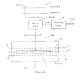
- Figure 1A depicts a position sensing system 100 according to the present disclosure, which shows the side view of the rotatable shaft 108 in the position sensing system 100.
- the position sensing system 100 includes a magnet device 102, a sensing device 104, a processing circuit 106 and a rotatable shaft 108.
- the sensing device 104 is electrically connected to the processing circuit 106 through a link 109, and the magnet device 102 is mounted on the rotatable shaft 108 and adapted to rotate together with the rotatable shaft 108 around the axis 112 (as shown in Figure 1C ) of the rotatable shaft 108.
- the sensing device 104 is positioned above and separated from the magnet device 102 with a distance D (or air gap) 183.
- the magnet device 102 When rotating around the axis 112 of the rotatable shaft 108, the magnet device 102 can cause magnetic flux density changes, which in turn causes magnetic field changes, to a position (or a detecting position) where the sensing device 104 is located.
- the sensing device 104 can generate electrical signals (such as PWM, SENT, etc) when subjected to the magnetic flux density changes/magnetic field changes from the magnet device 102.
- the sensing device 104 may include a Hall-effect circuitry for generating electrical signals in response to the magnetic field changes caused by the magnetic flux density changes.
- the sensing device 104 applies the sensed electrical signals to the processing circuit 106, which in turn generates a binary state signal 110 at its output terminal (i.e. link 111) in response to the sensed electrical signals.
- the rotatable shaft 108 can move linearly along its longitude direction and rotate around its axis 112 (as shown in Figure 1C ).
- the processing circuit 106 maintains its binary voltage state signal at its output 111.
- the binary state output 111 of the processing circuit 106 does not change its binary state output in response to the linear motion of the rotatable shaft 108 because the sensing device 104 cannot detect any magnetic flux density changes and/or magnetic field changes from the liner movement of the rotatable shaft.
- the processing circuit 106 may change its binary voltage state between V high and V low at its output 111, depending on the rotation angle of the rotatable shaft 108. In other words, the processing circuit 106 switches its binary state output 111 between V high and V low in response to the rotation angle of the rotatable shaft 108.
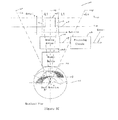
- Figure 1B depicts the position sensing system 100 of Figure 1 , which shows the top view of the rotatable shaft 108.
- the sensing device 104 should be drawn in a position above the magnet device 102 (with the distance D 183).
- the sensing device 104 is illustratively positioned at the lateral side of the rotatable shaft 108 in Figure 2 , but using a dot line 109 to reflect the above-below positional relationship between the magnet device 102 and the sensing device 104.
- the magnet device 102 has a length L along the longitude direction of the rotatable shaft 108 to ensure that the sensing device 104 is always within the effective detecting region of the magnet device 102 when the rotatable shaft 108 linearly moves along its longitude direction.
- the dotted line 114 indicates a center line along the longitude direction of the rotatable shaft 108 and the dotted lines 115 and 117 define a rotation range (-L1, +L1) of the rotatable shaft 108. In other words, when the rotatable shaft 108 rotates left and right around its axis 112, the center line 114 rotate towards the dotted lines 115 and 117, respectively.
- Figure 1C depicts the position sensing system 100 of Figure 1B , which shows the sectional view of the rotatable shaft 108 along the line A-A in Figure 1B .
- the rotatable shaft 108 can rotate from its center position (as indicated by the center line 113 in the diameter direction of the rotatable shaft 108) towards its left until it reaches its left rotation limitation -Lm (as indicated dotted line 121) or towards right until it reaches its right rotation limitation +Lm (as indicated by dotted line 123).
- the center line 113 passes and dissects the center line 114 and the axis 112 of the rotatable shaft 108.
- the two dotted lines 121 and 123 define a whole (or maximum) rotation range (-Lm, +Lm) for the rotatable shaft 108.
- the two dotted lines 115 and 117 define an internal rotation range (-L1, +L1) for the rotatable shaft 108.
- the whole rotation range and the internal rotation range are symmetrical in reference to the axis 112 and the center line 113 on the rotatable shaft 108. That is, the rotation ranges between -Lm and -L1 are equal to those between +Lm and +L1, respectively, in reference to the axis 112 and the center line 113.
- non-symmetrical arrangements of the rotation ranges are possible to a person skilled in the art.
- the center line 113 at the diameter direction of the rotatable shaft 108 is a straight line that passes through the axis 112 and is normal to the center line 114 along the longitude direction of the rotatable shaft 108.
- the sensing device 104 and the processing circuit 106 can detect the angular position of the rotatable shaft 108 and generating a binary state indication signal 107 on the output 111.
- the processing circuit 106 can generate a first signal state (a high voltage state V high as shown in Figure 1C or a low voltage state V low as shown in Figure 9B ) when the rotatable shaft 108 is within the rotation range (-L1, +L1); the processing circuit 106 generates a second signal state (a low voltage state V low as shown in Figure 1C or a high voltage state V high as shown in Figure 9B ) when the rotatable shaft 108 is outside (or beyond) the rotation range (-L1, +L1).
- the binary state indication signal 107 is then applied to an ECU (Engine Control Unit) 902 through the output terminal 111 of the processing circuit 106 (as shown Figure 10 ).
- Figure 2 depicts an exemplary implementation of the magnet device 102 and the sensing device 104 shown in Figures 1A-C .
- the magnet device 102 includes a magnet 204 having a south pole and a north pole.
- the south pole of the magnet 204 is attached on the surface of the rotation shaft 108.
- the front surface 205 of the sensing device 104 and the surface of the north pole of the magnet 204 are positioned facing with each other.
- the south pole and north pole of the magnet 204 are aligned with the axis 112 and the radial center line 113 on the rotatable shaft 108.
- the sensing device 104 is separated from the magnet 204 by a distance (or air gap) D 183 and coplanar with the magnet 204.
- the magnet 204 has a length L and the longitude center line 114 along the longitude direction of the rotatable shaft 108.
- the sensitive point of the sensing device 104 is aligned with the longitude center line 114 of the magnet 204.
- the sensing device 104 includes a sensing element 202, which can be a Hall-effect sensing device or magneto-resistive (MR) sensing device that is capable of generating an electrical signal when exposed to a rotating magnetic field. More specifically, a Hall-effect sensing element 202 can be a current-carrying semi-conductor membrane to generate a low voltage perpendicular to the direction of the current flow when subjected to magnetic flux density changes/magnetic field changes normal to the surface of the membrane. As shown in Figure 2 , the magnetic flux density changes/magnetic field changes within the air gape 183 along three dimensions 203 (B x , B y , B z ).
- MR magneto-resistive
- the sensing device 104 is typically designed to detect the magnetic field changes along one of the B x , or B y , or both.
- the sensing element 202 can be configured on a detecting position that is sensitive and responsive to the magnetic flux density changes/magnetic field changes caused by the rotating magnet 204.
- B stands for magnetic flux density
- B x indicates the magnetic flux density measurement along the radial direction of the shaft 108 and perpendicular to the sensing element 202
- By indicates the magnetic flux density measurement that is tangential to the shaft 108 and coplanar to the sensing element 202.
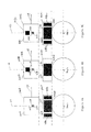
- Figures 3A-C depict three embodiments of the sensing system 100 shown in Figures 1A-C .
- the sensing device 104A has a front side 305A and a back side 306A and the magnet device 102A includes a bipolar magnet 304A having a south pole and a north pole.
- the south pole of the magnet 304A is attached on the surface of the rotation shaft 108.
- the front surface 305A of the sensing device 104A and the surface of the north pole of the magnet 304A are positioned facing with each other.
- the south pole and north pole of the magnet 304A are aligned with the radial center line 113 on the rotatable shaft 108.
- the sensing device 104A includes a sensing element 302A and is separated from the magnet 304A by a distance (or air gap) D 183 and coplanar with the magnet 304A.
- the bipolar magnet 304A and the detecting position (where the sensing element 302A is located) are in a same plane perpendicular to the axial direction of the rotation of the bipolar magnet 304A.
- a pair of magnet concentrators 308A1 and 308A2 are located at the two lateral sides of and adjacent to the bipolar magnet 304A, respectively.
- the sensing device 104B has a front side 305B and a back side 306B and the magnet device 102B includes a bipolar magnet 304B having a south pole and a north pole.
- the south pole of the magnet 304B is attached on the surface of the rotation shaft 108.
- the front surface 305B of the sensing device 104B and the surface of the north pole of the magnet 304B are positioned facing with each other.
- the south pole and north pole of the magnet 304B are aligned with the center line 113 on the rotatable shaft 108.
- the sensing device 104B includes a sensing element 302B and is separated from the magnet 304B by a distance (or air gap) D 183 and coplanar with the magnet 304B. Similar to the structure shown in Figure 3A , the bipolar magnet 304B and the detecting position (where the sensing element 302B is located) are in a same plane perpendicular to the axial direction of the rotation of the bipolar magnet 304B. To concentrate/condense the magnetic flux density generated by the magnet 304B, a magnetic flux density concentrator 309B is arranged at the back side of and adjacent to the sensing element 302B.
- the sensing device 104C has a front side 305C and a back side 306C and the magnet device 102C includes a bipolar magnet 304C having a south pole and a north pole.
- the south pole of the magnet 304C is attached on the surface of the rotation shaft 108.
- the front surface 305C of the sensing device 104C and the surface of the north pole of the magnet 304C are positioned facing with each other.
- the south pole and north pole of the magnet 304C are aligned with the center line 113 on the rotatable shaft 108.
- the sensing device 104C includes a sensing element 302C and is separated from the magnet 304C by a distance (or air gap) D 183 and coplanar with the magnet 304C. Similar to the structure shown in Figure 3A , the bipolar magnet 304C and the detecting position (where the sensing element 302C is located) are in a same plane perpendicular to the axial direction of the rotation of the bipolar magnet 304C. To concentrate/condense the magnetic flux density generated by the magnet 304C, a pair of magnet concentrators 308C1 and 308C2 that are located at the two lateral sides of and adjacent to the bipolar magnet 304C, respectively. To further concentrate/condense the magnetic flux density generated by the magnet 304C, a magnetic flux density concentrator 309C is arranged at the back side of and adjacent to the sensing element 302C.
- the distance between the sensing element 302B (or 302C) and concentrator 309B (or 309C) must be such that the magnetic field topology generated by 304B (or 304C) can be adjusted.
- the distance can be selected to be 0.1mm, but several variables are possible.
- the distance between the sensing element 302B (or 302C) and concentrator 309B (or 309C) can be selected from 0.1mm to 5mm.
- the distance between the magnet 304A or 304C (or 404A or 404C) and concentrators 308A1 and 308A2 (or 308C1 and 308C2) must be such that the magnetic field topology generated by 304A and 304C (or 404A and 404C) can be adjusted.
- the distance can be selected to be 0.1mm, but several variables are possible.
- the distance between the magnet 304A or 304C (or 404A or 404C) and concentrators 308A1 and 308A2 (or 308C1 and 308C2) can be selected to be 0.1mm to 10mm.
- the distance (or air gap) D 183 is determined/selected based on the parameters of the magnets 304A-C and 404A-C, including the magnet size, magnet properties, radius of rotation and expected performance. In one embodiment of the present disclosure, the distance (or air gap) D 183 is selected to be 2mm, but several variables are possible. For example, the distance (or air gap) D 183 can be selected to be 1mm to 3mm.
- the concentrator (308A1, 308A2, 308C1, 308C2, 309B and 309C) can be made from ferromagnetic materials or steels including metal alloys with large concentration of iron, non-exotic materials and non-precious metals.
- the magnets 304A-C shown in Figures 3A-C have a length L along the longitude direction of the rotatable shaft 108.
- the sensitive point of the sensing elements 302A-C shown in Figure 3-C are aligned with the center line 114 of the magnet 304A-C.
- the sensing element 302A, 302B, or 302 can be a Hall-effect sensing device or magneto-resistive (MR) sensing device.
- Figures 4A-C depict three additional embodiments of the position sensing system 100 shown in Figures 1A-C .
- each of the north poles of the magnets 404A-C is attached on the surface of the rotation shaft 108.
- the front surfaces 305A-C of the sensing device 104A-C and the surfaces of the south poles of the magnet 404A-C are positioned facing with each other, respectively.
- the north poles and south poles of the magnet 404A-C are aligned with the center line 113 on the rotatable shaft 108.
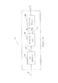
- FIG. 5A depicts one embodiment of the processing circuit 1065 in the position sensing system 100 in greater detail.
- the processing circuit 106 includes an A/D convertor 502, a digital processing unit 504 and an indicating circuit 508, all of which are electronically connected together through links 503, 505 and 507.
- the A/D convertor 502 Being electrically connected to the sensing device 104 through the link 109, the A/D convertor 502 receives analog electronic signals as inputs from the sensing device 104 (or 104A-C), processes the analog electronic signals into digital electronic signals, and applies the digitized electronic signals to the processing unit 504 through the link 503.
- the processing unit 504 then processes the digitized electronic signals to determine whether the rotatable shaft 108 is within the rotation range (-L1, +L1).
- the processing unit 504 sets the binary state output 111 of the indicating circuit 508 into a first signal state (a high voltage state V high as shown in Figure 1C or a low voltage state V low as shown in Figure 9B ) when the rotatable shaft 108 is within the rotation range (-L1, +L1); the processing unit 504 sets the binary state output 111 of the indicating circuit 508 into a second signal state (a low voltage state V low as shown in Figure 1C or a high voltage state V high as shown in Figure 9B ) when the rotatable shaft 108 is outside (or beyond) the rotation range (-L1, +L1).
- a first signal state a high voltage state V high as shown in Figure 1C or a low voltage state V low as shown in Figure 9B
- a second signal state a low voltage state V low as shown in Figure 1C or a high voltage state V high as shown in Figure 9B
- the binary state output 111 of the indicating circuit 508 can be set either in a high voltage state (V high ) or a low voltage state (V low ) depending on the two control signals on the links 505 and 507, namely, the state control signal (having a first control signal state and a second control signal state) on the link 505 and the trigger signal (or a trigger pulse) on the link 507.
- the state control signal having a first control signal state and a second control signal state
- the trigger signal or a trigger pulse
- the indicating circuit 508 When no trigger signal is applied onto the link 507, the indicating circuit 508 remains its current output state regardless the voltage state of the state control on the link 505.
- the logic function of the indicating circuit 508 can be implemented by using a J-K register or a D register.
- the processing unit 504 determines that the rotatable shaft 108 is within the rotation range ( ⁇ L1, +L1), it applies a first control signal state (a high control state signal or a low control state signal) on the link 505 and a trigger signal on the link 507, which sets the indicating circuit 508 into the first signal state (a high voltage state V high as shown in Figure 1C or a low voltage state V low as shown in Figure 9B ).
- a first control signal state a high control state signal or a low control state signal
- the processing unit 504 determines that the rotatable shaft 108 is outside (or beyond) the rotation range (-L1, +L1), it applies a second control signal state (a low control state signal or a high control state signal) on the link 505 and a trigger signal on the link 507, which sets the indicating circuit 508 into the second signal state (a low voltage state V low as shown in Figure 1C or a high voltage state V high as shown in Figure 9B ).
- a second control signal state a low control state signal or a high control state signal
- FIG. 5B depicts another embodiment of the processing circuit 1065 in the position sensing system 100 in greater detail.
- the processing circuit 106' includes an analog processing unit 924 and a polarity circuit 928.
- the analog processing unit 924 has an input that is coupled to the link 109 and an output that is coupled to the polarity circuit 928 through a link 925.
- the polarity circuit 928 has an output that is coupled to the output terminal 111.
- the analog processing unit 924 receives electronic signals from the sensing device 104 (or 104A-C) and processes them to generate a first state driving signal when the rotatable shaft 108 is within the rotation range (-L1, +L1) and to generate a second state driving signal when the rotatable shaft 108 is outside (or beyond) the rotation range (-L1, +L1).
- the polarity circuit 928 In response to the first state driving signal, the polarity circuit 928 is set to a first state signal (a high voltage state V high as shown in Figure 1C or a low voltage state V low as shown in Figure 9B ); in response to the second state driving signal, the polarity circuit 928 is set a second state signal (a low voltage state V low as shown in Figure 1C or a high voltage state V high as shown in Figure 9B ).
- a threshold voltage is calibrated (or simulated) using the process in connection with the description for Figure 8B .
- the calibrated (or simulated) threshold voltage is then set within the analog processing unit 924.
- the analog processing unit 924 When the sensed voltage from the sensing device 104 is greater or equal to the threshold voltage, the analog processing unit 924 generates a first state driving signal to set the polarity circuit 928 into a first state signal (a high voltage state V high as shown in Figure 1C or a low voltage state V low as shown in Figure 9B ).
- the analog processing unit 924 When the sensed voltage from the sensing device 104 (or 104A-C) is less than the threshold voltage, the analog processing unit 924 generates a second state driving signal to set the polarity circuit 928 into a second state signal (a low voltage state V low as shown in Figure 1C or a high voltage state V high as shown in Figure 9B ).
- the analog processing unit 924 can be implemented using a low-pass filter or some similar devices.
- Figure 6 depicts the processing unit 504 shown in Figure 5 in greater detail.
- the processing unit 504 includes a processor (or CPU) 602, a register 604, a memory device 606, an I/O circuit 608 and a buss 610.
- the processor 602, register 604, memory device 606 and I/O circuit 608 are coupled to the buss 610 through links 603, 605, 607 and 609, respectively.
- the memory device 606 can store programs (i.e., a set of instructions), parameters (such as the reference voltages as shown in Figures 7B and 8B ) and data (including the digitized electronic signals), the registers 604 can store the parameters and data, and the I/O circuit 608 can receive input signals into and send output signals out of the processing unit 504 (such as to the links 505 and 507).
- the registers 604 can provide and remain signals based on the contents stored therein for one or more CPU operation cycles so that the processor 602 can perform operations within the CPU operation cycles.
- the processor (or CPU) 602 can control the operation of the registers 604, memory device 606 and I/O circuit 608 and can perform reading/writing operations on the registers 604 and memory device 606.
- the I/O circuit 608 can receive input signals from the A/D convertor 502 and send out the output signals from the processor (or CPU) 602 to the indicating circuit 508.
- the processor (or CPU) 602 includes a logic operation unit (not shown) having a comparator 612, which can perform comparing operation from two sources of inputs 613 and 615 to generate a comparison result on output 617.
- the processor (or CPU) 602 can determine the subsequent operation based on the comparison result on output 617. More specifically, based on the comparison results, the processor (or CPU) 602 can generate a desirable state control signal and a trigger signal (or a trigger pulse) and send them to the links 505 and 507.
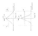
- Figure 7A depicts a bell-shaped function curve 702, which reflects the magnetic flux density changes/magnetic filed changes that are caused by the magnet 204 shown in Figure 2 in reference to the detecting point of the sensing element 202 along one dimension (X dimension or Y dimension) while the magnet 204 is rotating around the rotatable shaft 108.
- the bell-shaped function curve 702 is symmetrical to the vertical center line 703, which corresponds to the radial central position of the rotatable shaft 108.
- the magnetic flux density on the bell-shaped function curve 702 is at a minimum value when the magnet 204 is at the most distant position (corresponding to line 713) to the sensing device 104 shown in Figure 2 .
- the magnetic flux density on the bell-shaped function curve 702 gradually increases to a maximum value when the magnet 204 is rotating towards the closest distance position (corresponding to line 703) to the sensing device 104.
- the magnetic flux density on the bell-shaped function curve 702 then decreases to the minimum value when the magnet 204 is rotating from the closest distance position towards the most distant position (corresponding to line 711) to the sensing device 104.
- Figure 7B depicts a bell-shaped function curve 706, which reflects the magnetic flux density changes that are caused by the magnet (304A, 304B, 404A or 404B) and magnetic flux density concentrator(s) (308A1, 308A2; 308C1, 308C2; 309B; or 309C) as shown in Figures 3A-B and 4A-B in reference to the detecting point of the sensing element (302A or 302B) along one dimension (X dimension or Y dimension) while the magnet (304A, 304B, 404A or 404B) is rotating around the rotatable shaft 108.
- bell-shaped function curve 706 is symmetrical to the vertical center line 707, which corresponds to the radial central position of the rotatable shaft 108.
- the magnetic flux density on the function curve 706 is at a minimum value when the magnet (304A, 304B, 404A or 404B) is at the most distant position (corresponding to line 713) to the sensing device 104A or 104B shown in Figures 3A-B and 4A-B .
- the magnetic flux density on the bell-shaped function curve 706 gradually increases to a maximum value when the magnet (304A, 304B, 404A or 404B) is rotating towards the closest distance position (corresponding to line 707) to the sensing device 104A or 104B.
- the magnetic flux density on the bell-shaped function curve 706 decreases to the minimum value when the magnet (304A, 304B, 404A or 404B) is rotating from the closest distance position towards the most distant position (corresponding to line 711) to the sensing device 104A or 104B.
- the line 704 indicates the magnetic flux density at the seventy percent (70%) value of the difference between the magnetic flux density maximum and the magnetic flux density minimum on the bell-shaped function curve line 702.
- the line 708 indicates the magnetic flux density at seventy percent (70%) value of the difference between the magnetic flux density maximum and the magnetic flux density minimum on the bell-shaped function line 706.
- the density output ratio G2 on the bell-shaped function curve 706 is greater than the density output ratio G1 (G2 > G1) on the bell-shaped function curve 702 because the function curve 706 is steeper than the function curve 702.
- Figure 8A depicts a bell-shaped function curve 802, which reflects the voltage outputs that are sensed by the sensing element 202 as shown in Figure 2 in response to the magnetic flux density changes/magnetic field changes according to the bell-shaped function curve 702 shown in Figure 7A .
- Figure 8B depicts a bell-shaped function curve 806, which reflects the voltage outputs that are sensed by the sensing element (302A or 302B) shown in Figures 3A, 3B , 4A or 4B in response to the magnetic flux density changes/magnetic field changes according to the bell-shaped function curve 706 shown in Figure 7B .
- the bell-shaped function curve 802 (a voltage function curve) shown in Figure 8A is proportional to the bell-shaped function curve 702 (a magnetic density function curve) shown in Figure 7A .
- the bell-shaped function curve 808 (a voltage function curve) shown in Figure 8B is proportional to the bell-shaped function curve 708 (a magnetic density function curve) shown in Figure 7B .
- the voltage output ratio G4 on the voltage function curve 806 is greater than the voltage output ratio G3 (G4 > G3) on the voltage function curve 802 because the voltage function curve 806 is steeper than the voltage function curve 802.
- the line 804 indicates the voltage at the seventy percent (70%) value of the difference between the voltage maximum and the voltage minimum on the function curve 802.
- the line 808 indicates the voltage at seventy percent (70%) value of the difference between the voltage maximum and the voltage minimum on the function curve line 806.
- the voltage output curve 806 and the threshold line 808 can be generated in a calibration (or simulation) process. Specifically, when the magnet device 304A (or 304B) is constantly rotating around the axis 112 of the rotatable shaft 108, the sensing device 104A (or 104B) generates electrical signals that comply with the function curve 806 in response to the magnetic flux density changes/magnetic field changes generated by the magnet device 102A (or 102B) along one dimension (X dimension or Y dimension).
- a processing device In performing the calibration (or simulation) process, a processing device (such as the processing circuit 106) processes the analog electronic signals that comply with the function curve 806 (shown in figure 8B ) to generate a threshold voltage as indicated by line 808. Specifically, within the processing circuit 106, the A/D convertor 502 receives analog electronic signals (that comply the function curve 806) from the sensing device 104A (or 104B), converts them into digital electronic signals, and applies the digitized electronic signals to the I/O circuit 608 in the processing unit 504.
- the Predetermined Percentage Value is selected as 70%, but other Percentage Value is possible.
- Figure 8C depicts a scheme to form a binary state signal 107 having a first signal state (a high voltage V high ) and a second signal state (a low voltage V low ) based on the bell-shaped function curve 806 in the calibration (or simulation) process.
- the digital processing circuit 106 shown in Figure 5A (or the analog processing circuit 106' shown in Figure 5B ) generates the binary state signal 107 by matching all voltage points (or voltages) on the bell-shaped function curve 806 that are equal to or greater than the threshold voltage 808 as a first binary state signal (a high voltage V high ); and by matching all voltage points (or voltages) on the bell-shaped function curve 806 that are less than the threshold voltage 808 as a second binary state signal (a low voltage V low ).
- the electronic signals as shown in Figure 8B can be observed from an oscilloscope when the calibration (or simulation) outputs are applied to the oscilloscope.
- the width of the binary state signal 107 can be compensated by adjusting the value of the threshold voltage 808.
- the threshold voltage 808 generated in the calibration (or simulation) process is stored into the memory device 506 so that the processing circuit 504 can later use it to detect the rotation range of the rotatable shaft 108 in field use.
- the threshold voltage 808 generated in the calibration (or simulation) process is set into the analog processing unit 924 so that the analog processing unit 924 can use it to detect the rotation range of the rotatable shaft 108 in field use.
- the electronic-contactless sensing devices inevitably encounter operating condition variations in manufacturing and/or in operation, including, but not limited to, the variations in air gaps, temperature and the parameter variations in the components used.
- the adjustment/compensation capability is critical for measurement accuracy, especially for detecting the neutral position range for a gear shaft on automobile vehicles.
- the basis for the adjustment/compensation is the usage of a binary state signal to indicate an angular position range.
- the calibration (or simulation) process can be performed in field use by executing the calibration (or simulation) programs that are stored in the processing circuit 106.
- the width of the binary state signal can adjusted by monitoring and updating the minimum and maximum peaks of the electronic signals that comply with the bell-shaped function curve (806). Such an approach is a feasible and effective way to adjust the binary state signal.
- Figures 9A-B illustrates that either a positive binary state signal 107 or a negative binary state signal 107' can be used to indicate the rotation range (-L1, +L1) for the rotatable shaft 108.
- the digital processing circuit 106 shown in Figure 5A sets the indicating circuit 508 in a high voltage state V high as indicated by line 907; when the rotatable shaft 108 is beyond (or outside of) the rotation range (-L1, +L1), the processing unit 504 in the digital processing circuit 106 sets the indicating circuit 508 in a low voltage state V low as indicated by line 909.
- the binary state signal 107' can be a reverse of the binary state signal 107. Therefore, in Figure 9B , when the rotatable shaft 108 is within the rotation range (-L1, +L1), the processing circuit 106 shown in Figure 5A sets the indicating circuit 508 in a low voltage state V low as indicated by line 917; when the rotatable shaft 108 is beyond (or outside of) the rotation range (-L1, +L1), the processing unit 504 sets the indicating circuit 508 in a high voltage state V high as indicated by line 919.
- FIG 10 depicts an engine control system 900 in which the binary output 111 of the processing circuit 106 (or processing circuit 106') is used to control the engine in an automobile vehicle.
- the engine control system 900 includes the sensing device 104, the processing circuit 106 and an ECU (Engine Control Unit) 902.
- the rotatable shaft 108 is used as a gear shift lever and the rotation range (-L1, +L1) reflects the neutral position range of the gear shift lever.
- the ECU (Engine Control Unit) 902 receives the binary state signal on link 111 as its input from the processing circuit 106 and receives the input 903 from clutch sensing circuitry (not shown) of the automobile vehicle.
- the input 903 indicates whether the clutch of the automobile vehicle is being pressed.
- the ECU 902 detects that the gear shift lever stays within the neutral position range based on the binary state signal on link 111 for a certain period of time (5 seconds for example), it shuts down the engine of the automobile vehicle to save gas.
- the ECU 902 detects that the clutch of the automobile vehicle is being pressed based on the inputs on the link 903, the ECU 902 further detects whether the gear shift lever is within the neutral position range based on the binary state signal on link 111.
- the ECU 902 starts the engine only when the gear shift lever is within the neutral position range. Therefore, the detection accuracy of the neutral position range for the gear shift lever is important to ensure the appropriate operation of the automobile vehicle.
- the bell-shaped function line 806 can generate a binary state signal that is narrower in reference to the rotation angle arrange of the rotatable shaft 108 than the bell-shaped line 802 does. It should be appreciated that a narrower binary state signal 107 is especially desirable especially when the position sensing system 100 is used to detect the neutral position range for the gear shift lever in an automobile vehicle.
- the digital processing circuit 106 as shown in Figure 5A or the analog processing circuit 106' as shown in Figure 5B sets the indicating circuit 508 into the first signal state and the second signal state in response to the rotation angle of the rotatable shaft 108 using the steps as follows:
- the processor (CPU) 602 compares the sensed voltage with the threshold voltage 808. If the value of the sensed voltage is equal to or is greater than the threshold voltage 808, the processor (CPU) 602 generates corresponding state control signal and trigger signal on the links 505 and 507, respectively, to set the indicating circuit 508 into a first signal state (a high voltage state V high as shown in Figure 1C or a low voltage state V low as shown in Figure 9B ).
- the processor (CPU) 602 If the value of the sensed voltage is less than the threshold voltage 808, the processor (CPU) 602 generates the corresponding state control signal and trigger signal on the links 505 and 507, respectively, to set the indicating circuit 508 into a second signal state (a low voltage state V low as shown in Figure 1C or a high voltage state V high as shown in Figure 9B ).
- the programs (or instruction sets) to perform the specific steps for setting the indicating circuit 508 can be stored in the memory device 606 and executed by the processor (CPU) 602.
- the sensing device 104A when the rotatable shaft 108 is being rotated with a rotation angle, the sensing device 104A (or 104B) generates an electronic signal in response to the magnetic flux density changes and/or magnetic field changes caused by the magnet device 102A or 102B along one dimension (X dimension and/or Y dimension).
- the sensed electronic signal complies with the bell-shaped function curve 808 shown in Figure 8B .
- the analog processing unit 924 When the sensed voltage of the electric signal from the sensing device 104A (or 104B) is greater or equal to the threshold voltage, the analog processing unit 924 generates a first state driving signal to set the polarity circuit 928 into a first state signal (a high voltage state V high as shown in Figure 1C or a low voltage state V low as shown in Figure 9B ). When the sensed voltage of the electric signal from the sensing device 104A (or 104B) is less than the threshold voltage, the analog processing unit 924 generates a second state driving signal to set the polarity circuit 928 into a second state signal (a low voltage state V low as shown in Figure 1C or a high voltage state V high as shown in Figure 9B ).
- One item of doing so is to change the sensor input from an A/D converter input to a logic binary input at this control unit. This can be realized on sensor side with a mechanical switch with disadvantages of low measurement accuracy and poor reliability.
- the position sensing system shown in Figure 3C or 4C can generate a bell-shaped function curve that is even steeper than those generated by the sensing system shown in Figures 3A-B and 4A-B because the position sensing system shown in Figure 3C or 4C have two sets of magnetic density concentrators 308C1, 308C2 and 309C.
- the implementation principle of generating a binary state signal for the position sensing system shown in Figure 3C or 4C are the same with that in connection with the position sensing systems shown in Figures 3A-B and 4A-B . Therefore, the position sensing system shown in Figure 3C or 4C can generate a binary state signal that is narrower than that in the sensing system shown in Figures 3A-B and 4A-B .
Landscapes
- Physics & Mathematics (AREA)
- General Physics & Mathematics (AREA)
- Electromagnetism (AREA)
- Engineering & Computer Science (AREA)
- Power Engineering (AREA)
- Transmission And Conversion Of Sensor Element Output (AREA)
- Measurement Of Length, Angles, Or The Like Using Electric Or Magnetic Means (AREA)
Abstract
Description
- The present disclosure relates generally to a magnet device and a position sensing device, and in particular, to a magnet device that is used in a position sensing device for detecting an angular position range of a rotatable shaft.
- It is know in the industry to use position sensing devices to detect angular positions of a rotatable shaft.
- Traditionally, mechanical-contacted position sensing devices are used to detect angular positions of a rotatable shaft. However, mechanical-contacted position sensing devices have some shortcomings including mechanical wear, low angle accuracy and reliability and no diagnostic capability.
- There has been a proposal to use an electronic sensing system to generate binary signals to reflect angular positions of a rotatable shaft. Specifically, the electronic sensing system includes a sensing device for generating analog electrical signals in response to the rotation of the rotatable shaft and the electronic sensing system further processes the analog signals to generate the binary signals to indicate the angular position of the rotatable shaft. More specifically, a magnet device is attached on the rotatable shaft and adapted to rotate together with the rotatable shaft. The magnet device causes magnetic flux density changes/magnetic field changes to the sensing device while it is rotating around the rotatable shaft. The sensing device generates analog electrical signals in response to the magnetic flux density changes/magnetic field changes and the analog electric signals are then converted into binary signals.
- Therefore, there is a need to provide an improved magnet device for generating magnetic flux density changes/magnetic field changes that more accurately reflect the angular position of a rotatable shaft.
- There is another need to provide an improved sensing device to generate binary state signals to more accurately reflect the angular position of a rotatable shaft using the magnetic flux density changes/magnetic field changes.
- In a first aspect, the present disclosure provides a magnet device for providing the magnetic density changes/magnetic field changes in relation to a detecting position, which comprises:
- a magnet member adapted to be mounted on a rotatable shaft and be rotated therewith, the magnet member producing the magnetic density changes/magnetic field changes in relation to the detecting position when the magnet member is rotating around the rotatable shaft; and
- a magnetic flux density concentrator to concentrate/condense the density of the magnetic density changes/magnetic field changes.
- According to the first aspect, the magnet device is use with a sensing device, which has the detecting position where a sensing element is located, wherein:
- the sensing device includes the sensing element having a front side and a back side;
- the magnetic flux density concentrator includes a magnetic flux density concentrator element positioned adjacent to the back side of the sensing element.
- According to the first aspect of the magnet device, wherein:
- the magnet member has a first lateral side and a second lateral side that are located in the opposite sides of the magnet member;
- the magnetic flux density concentrator further includes a first and a second magnetic flux density concentrator elements;
- the first magnetic flux density concentrator element is positioned adjacent to the first lateral side of the magnet member; and
- the second magnetic flux density concentrator element is positioned adjacent to the second lateral side of the magnet member.
- According to a second aspect, the present disclosure provides a position sensing system for generating binary state signals to indicate the angular position range for a rotatable shaft, which comprises:
- a magnet device described in the first aspect, which generates the magnetic density changes/magnet field changes;
- a sensing device for generating electronic signals in response to the magnetic density changes/magnetic field changes; and
- a processing circuit for generating the binary state signals in response to the electronic signals.
- According to the second aspect of the position sensing system, wherein:
- the processing circuit comprises a threshold circuit for providing a threshold voltage on a bell-shaped function curve; and
- an indicating circuit;
- wherein the indicating circuit generates a first signal state when the voltage of the sensed electrical signals is above (or below) the threshold voltage and generates a second signal state when the voltage of the sensed electrical signal is below (or above) the threshold voltage.
- According to the second aspect of the position sensing system, wherein:
- the threshold voltage and the bell-shaped function curve are calibrated prior to installation of the position sensing system in response to the magnetic flux density changes/magnetic field changes in one dimension when the bipolar magnet rotates around the rotatable shaft for 360 degrees.
- According to the second aspect, the position sensing system further comprises:
- an adjusting circuit for adjusting width of the binary state signal to compensate variations of operating condition including variations in air gaps and temperature and parameter variations in components used, by monitoring and updating the min and max peaks of the electronic signals that comply with the bell-shaped function curve.
- By providing the magnet device and the position sensing system, the present disclosure overcomes the above mentioned shortcomings in the existing art.
- The present invention will be described with reference to the accompanying drawings, wherein:
-
Figure 1A depicts aposition sensing system 100 according to the present disclosure, which shows a side view of therotatable shaft 108 in theposition sensing system 100; -
Figure 1B depicts theposition sensing system 100 ofFigure 1A , which shows the top view of therotatable shaft 108 shown inFigure 1A ; -
Figure 1C depicts theposition sensing system 100, which shows the sectional view of therotatable shaft 108 shown inFigure 1B along the line A-A inFigure 1B ; -
Figure 2 depicts an exemplary implementation of themagnet device 102 and thesensing device 104 shown inFigures 1A-C ; -
Figures 3A-C depict three embodiments of themagnet device 102 andsensing device 104 shown inFigures 1A-C according to the present invention; -
Figures 4A-C depict three additional embodiments of themagnet devices 102A-C andsensing device 104A-C shown inFigures 1A-C according to the present invention; -
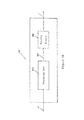
Figure 5A depicts one embodiment of theprocessing circuit 106 in theposition sensing system 100 in greater detail; -
Figure 5B depicts another embodiment of theprocessing circuit 106 in theposition sensing system 100 in greater detail; -
Figure 6 depicts theprocessing unit 504 shown inFigure 5A in greater detail; -
Figure 7A depicts a bell-shaped function curve 702, which reflects the magnetic flux density changes/magnetic field changes that are caused by themagnet 204 shown inFigure 2 ; -
Figure 7B depicts a bell-shaped function curve 706, which reflects the magnetic flux density changes/magnetic field changes that are caused by the magnet (304A, 304B, 404A or 404B) and magnetic flux density concentrator(s) (308A1, 308A2; 308C1, 308C2; 309B; or 309C) as shown inFigures 3A-B and4A-B ; -
Figure 8A depicts a bell-shaped function curve 802, which reflects the voltage outputs that are sensed by thesensing element 202 as shown inFigure 2 ; -
Figure 8B depicts a bell-shaped function curve 806, which reflects the voltage outputs that are sensed by the sensing element (302A or 302B) shown inFigures 3A, 3B ,4A or 4B ; -
Figure 8C depicts a scheme to form abinary state signal 107 having a first signal state and a second signal state based on the bell-shaped function curve 806 in the calibration (or simulation) process; -
Figures 9A-B illustrates using either a positivebinary state signal 107 or a negative binary state signal 1075 to indicate the rotation range for therotatable shaft 108 shown inFigures 1A-C ; and -
Figure 10 depicts anengine control system 900, in which the output 111 of theprocessing circuit 106 shown inFigures 1A-C is used to control the engine in an automobile vehicle. - Reference is now made to the embodiments, examples of which are illustrated in the accompanying drawings. In the detailed description of the embodiments, directional terminology, such as "top," "bottom," "above," "below," "left," "right," etc., is used with reference to the orientation of the Figure(s) being described. Because components of embodiments of the present disclosure can be positioned in a number of different orientations, the directional terminology is used for purposes of illustration and is in no way limiting. Whenever possible, the same or similar reference numbers and symbols are used throughout the drawings to refer to the same or similar parts.
-
Figure 1A depicts aposition sensing system 100 according to the present disclosure, which shows the side view of therotatable shaft 108 in theposition sensing system 100. - In
Figure 1A , theposition sensing system 100 includes amagnet device 102, asensing device 104, aprocessing circuit 106 and arotatable shaft 108. Thesensing device 104 is electrically connected to theprocessing circuit 106 through alink 109, and themagnet device 102 is mounted on therotatable shaft 108 and adapted to rotate together with therotatable shaft 108 around the axis 112 (as shown inFigure 1C ) of therotatable shaft 108. Thesensing device 104 is positioned above and separated from themagnet device 102 with a distance D (or air gap) 183. When rotating around the axis 112 of therotatable shaft 108, themagnet device 102 can cause magnetic flux density changes, which in turn causes magnetic field changes, to a position (or a detecting position) where thesensing device 104 is located. Thesensing device 104 can generate electrical signals (such as PWM, SENT, etc) when subjected to the magnetic flux density changes/magnetic field changes from themagnet device 102. As an illustrative embodiment, thesensing device 104 may include a Hall-effect circuitry for generating electrical signals in response to the magnetic field changes caused by the magnetic flux density changes. Thesensing device 104 applies the sensed electrical signals to theprocessing circuit 106, which in turn generates abinary state signal 110 at its output terminal (i.e. link 111) in response to the sensed electrical signals. - As shown in
Figure 1A , therotatable shaft 108 can move linearly along its longitude direction and rotate around its axis 112 (as shown inFigure 1C ). When therotatable shaft 108 linearly moves along its longitude direction, theprocessing circuit 106 maintains its binary voltage state signal at its output 111. In other words, the binary state output 111 of theprocessing circuit 106 does not change its binary state output in response to the linear motion of therotatable shaft 108 because thesensing device 104 cannot detect any magnetic flux density changes and/or magnetic field changes from the liner movement of the rotatable shaft. However, when therotatable shaft 108 rotates around its axis 112, theprocessing circuit 106 may change its binary voltage state between Vhigh and Vlow at its output 111, depending on the rotation angle of therotatable shaft 108. In other words, theprocessing circuit 106 switches its binary state output 111 between Vhigh and Vlow in response to the rotation angle of therotatable shaft 108. -
Figure 1B depicts theposition sensing system 100 ofFigure 1 , which shows the top view of therotatable shaft 108. In the top view of therotatable shaft 108, thesensing device 104 should be drawn in a position above the magnet device 102 (with the distance D 183). To better illustrate the principle of the present disclosure, however, thesensing device 104 is illustratively positioned at the lateral side of therotatable shaft 108 inFigure 2 , but using adot line 109 to reflect the above-below positional relationship between themagnet device 102 and thesensing device 104. - As shown in
Figure 1B , themagnet device 102 has a length L along the longitude direction of therotatable shaft 108 to ensure that thesensing device 104 is always within the effective detecting region of themagnet device 102 when therotatable shaft 108 linearly moves along its longitude direction. The dotted line 114 indicates a center line along the longitude direction of therotatable shaft 108 and thedotted lines 115 and 117 define a rotation range (-L1, +L1) of therotatable shaft 108. In other words, when therotatable shaft 108 rotates left and right around its axis 112, the center line 114 rotate towards the dottedlines 115 and 117, respectively. -
Figure 1C depicts theposition sensing system 100 ofFigure 1B , which shows the sectional view of therotatable shaft 108 along the line A-A inFigure 1B . - As shown in
Figure 1C , therotatable shaft 108 can rotate from its center position (as indicated by thecenter line 113 in the diameter direction of the rotatable shaft 108) towards its left until it reaches its left rotation limitation -Lm (as indicated dotted line 121) or towards right until it reaches its right rotation limitation +Lm (as indicated by dotted line 123). Thecenter line 113 passes and dissects the center line 114 and the axis 112 of therotatable shaft 108. Hence, the twodotted lines rotatable shaft 108. Within the whole rotation range (-Lm, +Lm), the twodotted lines 115 and 117 define an internal rotation range (-L1, +L1) for therotatable shaft 108. In the embodiment as shown inFigure 1C , the whole rotation range and the internal rotation range are symmetrical in reference to the axis 112 and thecenter line 113 on therotatable shaft 108. That is, the rotation ranges between -Lm and -L1 are equal to those between +Lm and +L1, respectively, in reference to the axis 112 and thecenter line 113. However, non-symmetrical arrangements of the rotation ranges are possible to a person skilled in the art. In addition, it is possible to expand the whole rotation range (-Lm, +Lm) of therotatable shaft 108 to 360 degrees. To more clearly define the positional relationships among the components inFigures 1A-C , it should be noted that thecenter line 113 at the diameter direction of therotatable shaft 108 is a straight line that passes through the axis 112 and is normal to the center line 114 along the longitude direction of therotatable shaft 108. - Working together, the
sensing device 104 and theprocessing circuit 106 can detect the angular position of therotatable shaft 108 and generating a binary state indication signal 107 on the output 111. Specifically, theprocessing circuit 106 can generate a first signal state (a high voltage state Vhigh as shown inFigure 1C or a low voltage state Vlow as shown inFigure 9B ) when therotatable shaft 108 is within the rotation range (-L1, +L1); theprocessing circuit 106 generates a second signal state (a low voltage state Vlow as shown inFigure 1C or a high voltage state Vhigh as shown inFigure 9B ) when therotatable shaft 108 is outside (or beyond) the rotation range (-L1, +L1). The binarystate indication signal 107 is then applied to an ECU (Engine Control Unit) 902 through the output terminal 111 of the processing circuit 106 (as shownFigure 10 ). -
Figure 2 depicts an exemplary implementation of themagnet device 102 and thesensing device 104 shown inFigures 1A-C . - As shown in
Figure 2 , themagnet device 102 includes amagnet 204 having a south pole and a north pole. The south pole of themagnet 204 is attached on the surface of therotation shaft 108. The front surface 205 of thesensing device 104 and the surface of the north pole of themagnet 204 are positioned facing with each other. The south pole and north pole of themagnet 204 are aligned with the axis 112 and theradial center line 113 on therotatable shaft 108. Thesensing device 104 is separated from themagnet 204 by a distance (or air gap)D 183 and coplanar with themagnet 204. As indicated inFigure 1B , themagnet 204 has a length L and the longitude center line 114 along the longitude direction of therotatable shaft 108. To more effectively detecting the magnetic flux density changes from themagnet 204, as one embodiment, the sensitive point of thesensing device 104 is aligned with the longitude center line 114 of themagnet 204. - As shown in
Figure 2 , thesensing device 104 includes asensing element 202, which can be a Hall-effect sensing device or magneto-resistive (MR) sensing device that is capable of generating an electrical signal when exposed to a rotating magnetic field. More specifically, a Hall-effect sensing element 202 can be a current-carrying semi-conductor membrane to generate a low voltage perpendicular to the direction of the current flow when subjected to magnetic flux density changes/magnetic field changes normal to the surface of the membrane. As shown inFigure 2 , the magnetic flux density changes/magnetic field changes within theair gape 183 along three dimensions 203 (Bx, By, Bz). Thesensing device 104 is typically designed to detect the magnetic field changes along one of the Bx, or By, or both. Thesensing element 202 can be configured on a detecting position that is sensitive and responsive to the magnetic flux density changes/magnetic field changes caused by therotating magnet 204. InFigure 2 , B stands for magnetic flux density; Bx indicates the magnetic flux density measurement along the radial direction of theshaft 108 and perpendicular to thesensing element 202; and By indicates the magnetic flux density measurement that is tangential to theshaft 108 and coplanar to thesensing element 202. -
Figures 3A-C depict three embodiments of thesensing system 100 shown inFigures 1A-C . - As shown in
Figure 3A , thesensing device 104A has afront side 305A and aback side 306A and themagnet device 102A includes a bipolar magnet 304A having a south pole and a north pole. The south pole of the magnet 304A is attached on the surface of therotation shaft 108. Thefront surface 305A of thesensing device 104A and the surface of the north pole of the magnet 304A are positioned facing with each other. The south pole and north pole of the magnet 304A are aligned with theradial center line 113 on therotatable shaft 108. Thesensing device 104A includes asensing element 302A and is separated from the magnet 304A by a distance (or air gap)D 183 and coplanar with the magnet 304A. The bipolar magnet 304A and the detecting position (where thesensing element 302A is located) are in a same plane perpendicular to the axial direction of the rotation of the bipolar magnet 304A. To concentrate/condense the magnetic flux density generated by the magnet 304A, a pair of magnet concentrators 308A1 and 308A2 are located at the two lateral sides of and adjacent to the bipolar magnet 304A, respectively. - As shown in
Figure 3B , thesensing device 104B has a front side 305B and a back side 306B and the magnet device 102B includes abipolar magnet 304B having a south pole and a north pole. The south pole of themagnet 304B is attached on the surface of therotation shaft 108. The front surface 305B of thesensing device 104B and the surface of the north pole of themagnet 304B are positioned facing with each other. The south pole and north pole of themagnet 304B are aligned with thecenter line 113 on therotatable shaft 108. Thesensing device 104B includes asensing element 302B and is separated from themagnet 304B by a distance (or air gap)D 183 and coplanar with themagnet 304B. Similar to the structure shown inFigure 3A , thebipolar magnet 304B and the detecting position (where thesensing element 302B is located) are in a same plane perpendicular to the axial direction of the rotation of thebipolar magnet 304B. To concentrate/condense the magnetic flux density generated by themagnet 304B, a magnetic flux density concentrator 309B is arranged at the back side of and adjacent to thesensing element 302B. - As shown in
Figure 3C , the sensing device 104C has a front side 305C and a back side 306C and the magnet device 102C includes abipolar magnet 304C having a south pole and a north pole. The south pole of themagnet 304C is attached on the surface of therotation shaft 108. The front surface 305C of the sensing device 104C and the surface of the north pole of themagnet 304C are positioned facing with each other. The south pole and north pole of themagnet 304C are aligned with thecenter line 113 on therotatable shaft 108. The sensing device 104C includes a sensing element 302C and is separated from themagnet 304C by a distance (or air gap)D 183 and coplanar with themagnet 304C. Similar to the structure shown inFigure 3A , thebipolar magnet 304C and the detecting position (where the sensing element 302C is located) are in a same plane perpendicular to the axial direction of the rotation of thebipolar magnet 304C. To concentrate/condense the magnetic flux density generated by themagnet 304C, a pair of magnet concentrators 308C1 and 308C2 that are located at the two lateral sides of and adjacent to thebipolar magnet 304C, respectively. To further concentrate/condense the magnetic flux density generated by themagnet 304C, a magnetic flux density concentrator 309C is arranged at the back side of and adjacent to the sensing element 302C. - In
Figures 3B, 3C ,4B and 4C , the distance between thesensing element 302B (or 302C) and concentrator 309B (or 309C) must be such that the magnetic field topology generated by 304B (or 304C) can be adjusted. As one embodiment, the distance can be selected to be 0.1mm, but several variables are possible. For example, according to the magnetic field topology generated by 304B (or 304C), the distance between thesensing element 302B (or 302C) and concentrator 309B (or 309C) can be selected from 0.1mm to 5mm. - In
Figures 3A, 3C ,4A and 4C , the distance between themagnet 304A or 304C (or 404A or 404C) and concentrators 308A1 and 308A2 (or 308C1 and 308C2) must be such that the magnetic field topology generated by 304A and 304C (or 404A and 404C) can be adjusted. As one embodiment, the distance can be selected to be 0.1mm, but several variables are possible. For example, according to the magnetic field topology generated by 304A and 304C (or 404A and 404C), the distance between themagnet 304A or 304C (or 404A or 404C) and concentrators 308A1 and 308A2 (or 308C1 and 308C2) can be selected to be 0.1mm to 10mm. - In
Figures 3A-C and4A-C , the distance (or air gap)D 183 is determined/selected based on the parameters of the magnets 304A-C and 404A-C, including the magnet size, magnet properties, radius of rotation and expected performance. In one embodiment of the present disclosure, the distance (or air gap)D 183 is selected to be 2mm, but several variables are possible. For example, the distance (or air gap)D 183 can be selected to be 1mm to 3mm. The concentrator (308A1, 308A2, 308C1, 308C2, 309B and 309C) can be made from ferromagnetic materials or steels including metal alloys with large concentration of iron, non-exotic materials and non-precious metals. - As indicated in
Figure 1B , the magnets 304A-C shown inFigures 3A-C have a length L along the longitude direction of therotatable shaft 108. To more effectively detecting the magnetic flux density changes from the magnet 304A-C, as one implementation, the sensitive point of thesensing elements 302A-C shown inFigure 3-C are aligned with the center line 114 of the magnet 304A-C. Thesensing element -
Figures 4A-C depict three additional embodiments of theposition sensing system 100 shown inFigures 1A-C . - In
Figures 4A-C , the three additional embodiments have almost identical structures as those inFigures 3A-C , respectively, expect that the magnetic polarization orientation of the magnets 402A-C shown inFigures 4A-C is different from that of themagnets 302A-C shown inFigures 3A-C . As shown inFigures 4A-C , each of the north poles of themagnets 404A-C is attached on the surface of therotation shaft 108. The front surfaces 305A-C of thesensing device 104A-C and the surfaces of the south poles of themagnet 404A-C are positioned facing with each other, respectively. The north poles and south poles of themagnet 404A-C are aligned with thecenter line 113 on therotatable shaft 108. -
Figure 5A depicts one embodiment of the processing circuit 1065 in theposition sensing system 100 in greater detail. As shown inFigure 5A , theprocessing circuit 106 includes an A/D convertor 502, adigital processing unit 504 and an indicatingcircuit 508, all of which are electronically connected together throughlinks sensing device 104 through thelink 109, the A/D convertor 502 receives analog electronic signals as inputs from the sensing device 104 (or 104A-C), processes the analog electronic signals into digital electronic signals, and applies the digitized electronic signals to theprocessing unit 504 through thelink 503. Theprocessing unit 504 then processes the digitized electronic signals to determine whether therotatable shaft 108 is within the rotation range (-L1, +L1). Based on its determination, theprocessing unit 504 sets the binary state output 111 of the indicatingcircuit 508 into a first signal state (a high voltage state Vhigh as shown inFigure 1C or a low voltage state Vlow as shown inFigure 9B ) when therotatable shaft 108 is within the rotation range (-L1, +L1); theprocessing unit 504 sets the binary state output 111 of the indicatingcircuit 508 into a second signal state (a low voltage state Vlow as shown inFigure 1C or a high voltage state Vhigh as shown inFigure 9B ) when therotatable shaft 108 is outside (or beyond) the rotation range (-L1, +L1). - More specifically, the binary state output 111 of the indicating
circuit 508 can be set either in a high voltage state (Vhigh) or a low voltage state (Vlow) depending on the two control signals on thelinks link 505 and the trigger signal (or a trigger pulse) on thelink 507. When thedigital processing unit 504 applies a trigger pulse onto thelink 507 and a state control signal onto thelink 505, the indicatingcircuit 508 is set into a voltage state that is the same to that of the state control signal as being applied on thelink 505. When no trigger signal is applied onto thelink 507, the indicatingcircuit 508 remains its current output state regardless the voltage state of the state control on thelink 505. As an embodiment, the logic function of the indicatingcircuit 508 can be implemented by using a J-K register or a D register. - Therefore, when the
processing unit 504 determines that therotatable shaft 108 is within the rotation range (→ L1, +L1), it applies a first control signal state (a high control state signal or a low control state signal) on thelink 505 and a trigger signal on thelink 507, which sets the indicatingcircuit 508 into the first signal state (a high voltage state Vhigh as shown inFigure 1C or a low voltage state Vlow as shown inFigure 9B ). When theprocessing unit 504 determines that therotatable shaft 108 is outside (or beyond) the rotation range (-L1, +L1), it applies a second control signal state (a low control state signal or a high control state signal) on thelink 505 and a trigger signal on thelink 507, which sets the indicatingcircuit 508 into the second signal state (a low voltage state Vlow as shown inFigure 1C or a high voltage state Vhigh as shown inFigure 9B ). -
Figure 5B depicts another embodiment of the processing circuit 1065 in theposition sensing system 100 in greater detail. As shown inFigure 5B , the processing circuit 106' includes ananalog processing unit 924 and apolarity circuit 928. Theanalog processing unit 924 has an input that is coupled to thelink 109 and an output that is coupled to thepolarity circuit 928 through alink 925. Thepolarity circuit 928 has an output that is coupled to the output terminal 111. - The
analog processing unit 924 receives electronic signals from the sensing device 104 (or 104A-C) and processes them to generate a first state driving signal when therotatable shaft 108 is within the rotation range (-L1, +L1) and to generate a second state driving signal when therotatable shaft 108 is outside (or beyond) the rotation range (-L1, +L1). In response to the first state driving signal, thepolarity circuit 928 is set to a first state signal (a high voltage state Vhigh as shown inFigure 1C or a low voltage state Vlow as shown inFigure 9B ); in response to the second state driving signal, thepolarity circuit 928 is set a second state signal (a low voltage state Vlow as shown inFigure 1C or a high voltage state Vhigh as shown inFigure 9B ). - More specifically, a threshold voltage is calibrated (or simulated) using the process in connection with the description for
Figure 8B . The calibrated (or simulated) threshold voltage is then set within theanalog processing unit 924. When the sensed voltage from thesensing device 104 is greater or equal to the threshold voltage, theanalog processing unit 924 generates a first state driving signal to set thepolarity circuit 928 into a first state signal (a high voltage state Vhigh as shown inFigure 1C or a low voltage state Vlow as shown inFigure 9B ). When the sensed voltage from the sensing device 104 (or 104A-C) is less than the threshold voltage, theanalog processing unit 924 generates a second state driving signal to set thepolarity circuit 928 into a second state signal (a low voltage state Vlow as shown inFigure 1C or a high voltage state Vhigh as shown inFigure 9B ). - The
analog processing unit 924 can be implemented using a low-pass filter or some similar devices. -
Figure 6 depicts theprocessing unit 504 shown inFigure 5 in greater detail. As shown inFigure 6 , theprocessing unit 504 includes a processor (or CPU) 602, aregister 604, a memory device 606, an I/O circuit 608 and abuss 610. Theprocessor 602, register 604, memory device 606 and I/O circuit 608 are coupled to thebuss 610 throughlinks Figures 7B and8B ) and data (including the digitized electronic signals), theregisters 604 can store the parameters and data, and the I/O circuit 608 can receive input signals into and send output signals out of the processing unit 504 (such as to thelinks 505 and 507). Theregisters 604 can provide and remain signals based on the contents stored therein for one or more CPU operation cycles so that theprocessor 602 can perform operations within the CPU operation cycles. - By executing the programs stored in the memory device 606, the processor (or CPU) 602 can control the operation of the
registers 604, memory device 606 and I/O circuit 608 and can perform reading/writing operations on theregisters 604 and memory device 606. The I/O circuit 608 can receive input signals from the A/D convertor 502 and send out the output signals from the processor (or CPU) 602 to the indicatingcircuit 508. To perform comparison logic operation, the processor (or CPU) 602 includes a logic operation unit (not shown) having a comparator 612, which can perform comparing operation from two sources ofinputs 613 and 615 to generate a comparison result on output 617. The processor (or CPU) 602 can determine the subsequent operation based on the comparison result on output 617. More specifically, based on the comparison results, the processor (or CPU) 602 can generate a desirable state control signal and a trigger signal (or a trigger pulse) and send them to thelinks -
Figure 7A depicts a bell-shapedfunction curve 702, which reflects the magnetic flux density changes/magnetic filed changes that are caused by themagnet 204 shown inFigure 2 in reference to the detecting point of thesensing element 202 along one dimension (X dimension or Y dimension) while themagnet 204 is rotating around therotatable shaft 108. As shown inFigure 7A , the bell-shapedfunction curve 702 is symmetrical to thevertical center line 703, which corresponds to the radial central position of therotatable shaft 108. As shown inFigure 7A , the magnetic flux density on the bell-shapedfunction curve 702 is at a minimum value when themagnet 204 is at the most distant position (corresponding to line 713) to thesensing device 104 shown inFigure 2 . The magnetic flux density on the bell-shapedfunction curve 702 gradually increases to a maximum value when themagnet 204 is rotating towards the closest distance position (corresponding to line 703) to thesensing device 104. The magnetic flux density on the bell-shapedfunction curve 702 then decreases to the minimum value when themagnet 204 is rotating from the closest distance position towards the most distant position (corresponding to line 711) to thesensing device 104. -
Figure 7B depicts a bell-shapedfunction curve 706, which reflects the magnetic flux density changes that are caused by the magnet (304A, 304B, 404A or 404B) and magnetic flux density concentrator(s) (308A1, 308A2; 308C1, 308C2; 309B; or 309C) as shown inFigures 3A-B and4A-B in reference to the detecting point of the sensing element (302A or 302B) along one dimension (X dimension or Y dimension) while the magnet (304A, 304B, 404A or 404B) is rotating around therotatable shaft 108. As shown inFigure 7B , bell-shapedfunction curve 706 is symmetrical to thevertical center line 707, which corresponds to the radial central position of therotatable shaft 108. As shown inFigure 7B , the magnetic flux density on thefunction curve 706 is at a minimum value when the magnet (304A, 304B, 404A or 404B) is at the most distant position (corresponding to line 713) to thesensing device Figures 3A-B and4A-B . The magnetic flux density on the bell-shapedfunction curve 706 gradually increases to a maximum value when the magnet (304A, 304B, 404A or 404B) is rotating towards the closest distance position (corresponding to line 707) to thesensing device function curve 706 decreases to the minimum value when the magnet (304A, 304B, 404A or 404B) is rotating from the closest distance position towards the most distant position (corresponding to line 711) to thesensing device - In
Figure 7A , the line 704 indicates the magnetic flux density at the seventy percent (70%) value of the difference between the magnetic flux density maximum and the magnetic flux density minimum on the bell-shapedfunction curve line 702. InFigure 7B , theline 708 indicates the magnetic flux density at seventy percent (70%) value of the difference between the magnetic flux density maximum and the magnetic flux density minimum on the bell-shapedfunction line 706. - It should be noted that the bell-shaped
function curve 706 inFigure 7B is steeper than the bell-shapedfunction curve 702 inFigure 7A . To better compare the performance of the two bell-shaped function curves shown inFigures 7A-B , a density output ratio G1 based on the bell-shapedfunction curve 702 is defined as:
which is a ratio between H1 and W1 measured at a predetermined percentage (70% for example) of the magnetic flux density output on the bell-shapedfunction curve 702 where H1 stands for the magnetic flux density value at the predetermined percentage on bell-shapedfunction curve 702, and W1 stands for the rotation angle range which corresponds to the magnetic flux density value at the predetermined percentage on the bell-shapedfunction curve 702. - Likewise, a density output ratio G2 based on the bell-shaped
function curve 706 is defined as:
which is a ratio between H2 and W2 measured at the predetermined percentage (70% for example) of the magnetic flux density output on the bell-shapedfunction curve 706 where H2 stands for the magnetic flux density at the predetermined percentage on the bell-shapedfunction curve 706, and W2 stands for the rotation angle range which corresponds to the magnetic flux density value at the predetermined percentage on the bell-shapedfunction curve 706. - Therefore, the density output ratio G2 on the bell-shaped
function curve 706 is greater than the density output ratio G1 (G2 > G1) on the bell-shapedfunction curve 702 because thefunction curve 706 is steeper than thefunction curve 702. -
Figure 8A depicts a bell-shapedfunction curve 802, which reflects the voltage outputs that are sensed by thesensing element 202 as shown inFigure 2 in response to the magnetic flux density changes/magnetic field changes according to the bell-shapedfunction curve 702 shown inFigure 7A . -
Figure 8B depicts a bell-shapedfunction curve 806, which reflects the voltage outputs that are sensed by the sensing element (302A or 302B) shown inFigures 3A, 3B ,4A or 4B in response to the magnetic flux density changes/magnetic field changes according to the bell-shapedfunction curve 706 shown inFigure 7B . - As voltage outputs, the bell-shaped function curve 802 (a voltage function curve) shown in
Figure 8A is proportional to the bell-shaped function curve 702 (a magnetic density function curve) shown inFigure 7A . Likewise, the bell-shaped function curve 808 (a voltage function curve) shown inFigure 8B is proportional to the bell-shaped function curve 708 (a magnetic density function curve) shown inFigure 7B . - To better compare the performance of the two bell-shaped function curves shown in
Figures 8A-B , a voltage output ratio G3 based on thefunction line 802 is defined as:
which is a ratio between H3 and W3 measured at a predetermined percentage (70% for example) of the voltage outputs on the bell-shapedfunction curve 802 where H3 stands for the voltage at the predetermined percentage on the bell-shapedfunction curve 802, and W3 stands for the rotation angle range which corresponds to the voltage value at the predetermined percentage on the bell-shapedfunction curve 802. - Likewise, the voltage output ratio G4 based on the bell-shaped
function curve 806 is defined as:
which is a ratio between H4 and W4 measured at the predetermined percentage (70% for example) of the voltage output on the bell-shapedfunction curve 806 where H4 stands for the voltage at the predetermined percentage on the bell-shapedfunction curve 806, and W4 stands for the rotation angle range which corresponds to the voltage value at the predetermined percentage on bell-shapedfunction curve 806. - Therefore, the voltage output ratio G4 on the
voltage function curve 806 is greater than the voltage output ratio G3 (G4 > G3) on thevoltage function curve 802 because thevoltage function curve 806 is steeper than thevoltage function curve 802. - In
Figure 8A , theline 804 indicates the voltage at the seventy percent (70%) value of the difference between the voltage maximum and the voltage minimum on thefunction curve 802. InFigure 8B , the line 808 indicates the voltage at seventy percent (70%) value of the difference between the voltage maximum and the voltage minimum on thefunction curve line 806. - According to one embodiment, the
voltage output curve 806 and the threshold line 808 can be generated in a calibration (or simulation) process. Specifically, when the magnet device 304A (or 304B) is constantly rotating around the axis 112 of therotatable shaft 108, thesensing device 104A (or 104B) generates electrical signals that comply with thefunction curve 806 in response to the magnetic flux density changes/magnetic field changes generated by themagnet device 102A (or 102B) along one dimension (X dimension or Y dimension). - In performing the calibration (or simulation) process, a processing device (such as the processing circuit 106) processes the analog electronic signals that comply with the function curve 806 (shown in
figure 8B ) to generate a threshold voltage as indicated by line 808. Specifically, within theprocessing circuit 106, the A/D convertor 502 receives analog electronic signals (that comply the function curve 806) from thesensing device 104A (or 104B), converts them into digital electronic signals, and applies the digitized electronic signals to the I/O circuit 608 in theprocessing unit 504. After receiving the digitized electronic signals, the processor (CUP) 602 in theprocessing unit 504 stores them into the memory device 606 and then transform the digitized electronic signals into the threshold voltage 808 using the mathematical formula (5) as follows:
- In the present disclosure, the Predetermined Percentage Value is selected as 70%, but other Percentage Value is possible.
-
Figure 8C depicts a scheme to form abinary state signal 107 having a first signal state (a high voltage Vhigh) and a second signal state (a low voltage Vlow) based on the bell-shapedfunction curve 806 in the calibration (or simulation) process. Based on the mathematic formula (5), thedigital processing circuit 106 shown inFigure 5A (or the analog processing circuit 106' shown inFigure 5B ) generates thebinary state signal 107 by matching all voltage points (or voltages) on the bell-shapedfunction curve 806 that are equal to or greater than the threshold voltage 808 as a first binary state signal (a high voltage Vhigh); and by matching all voltage points (or voltages) on the bell-shapedfunction curve 806 that are less than the threshold voltage 808 as a second binary state signal (a low voltage Vlow). The electronic signals as shown inFigure 8B can be observed from an oscilloscope when the calibration (or simulation) outputs are applied to the oscilloscope. - In
Figure 8B , to cope with the variations in the operating condition of the position detecting system 100 (including the variations in air gaps and temperature and the parameters variations in components), the width of thebinary state signal 107 can be compensated by adjusting the value of the threshold voltage 808. According to one embodiment, the threshold voltage 808 generated in the calibration (or simulation) process is stored into the memory device 506 so that theprocessing circuit 504 can later use it to detect the rotation range of therotatable shaft 108 in field use. According to another embodiment, the threshold voltage 808 generated in the calibration (or simulation) process is set into theanalog processing unit 924 so that theanalog processing unit 924 can use it to detect the rotation range of therotatable shaft 108 in field use. - It should be noted that the electronic-contactless sensing devices inevitably encounter operating condition variations in manufacturing and/or in operation, including, but not limited to, the variations in air gaps, temperature and the parameter variations in the components used. The adjustment/compensation capability is critical for measurement accuracy, especially for detecting the neutral position range for a gear shaft on automobile vehicles. The basis for the adjustment/compensation (including width and/or offset) is the usage of a binary state signal to indicate an angular position range. To facilitate maintenance of the
position sensing system 100, the calibration (or simulation) process can be performed in field use by executing the calibration (or simulation) programs that are stored in theprocessing circuit 106. As one embodiment, the width of the binary state signal can adjusted by monitoring and updating the minimum and maximum peaks of the electronic signals that comply with the bell-shaped function curve (806). Such an approach is a feasible and effective way to adjust the binary state signal. -
Figures 9A-B illustrates that either a positivebinary state signal 107 or a negative binary state signal 107' can be used to indicate the rotation range (-L1, +L1) for therotatable shaft 108. - Specifically, as shown in
Figure 9A , when therotatable shaft 108 is within the rotation range (-L1, +L1), thedigital processing circuit 106 shown inFigure 5A sets the indicatingcircuit 508 in a high voltage state Vhigh as indicated byline 907; when therotatable shaft 108 is beyond (or outside of) the rotation range (-L1, +L1), theprocessing unit 504 in thedigital processing circuit 106 sets the indicatingcircuit 508 in a low voltage state Vlow as indicated byline 909. - Alternatively, as shown in
Figure 9B , the binary state signal 107' can be a reverse of thebinary state signal 107. Therefore, inFigure 9B , when therotatable shaft 108 is within the rotation range (-L1, +L1), theprocessing circuit 106 shown inFigure 5A sets the indicatingcircuit 508 in a low voltage state Vlow as indicated byline 917; when therotatable shaft 108 is beyond (or outside of) the rotation range (-L1, +L1), theprocessing unit 504 sets the indicatingcircuit 508 in a high voltage state Vhigh as indicated byline 919. -
Figure 10 depicts anengine control system 900 in which the binary output 111 of the processing circuit 106 (or processing circuit 106') is used to control the engine in an automobile vehicle. InFigure 10 , theengine control system 900 includes thesensing device 104, theprocessing circuit 106 and an ECU (Engine Control Unit) 902. In theengine control system 900, therotatable shaft 108 is used as a gear shift lever and the rotation range (-L1, +L1) reflects the neutral position range of the gear shift lever. - As shown in
Figure 10 , the ECU (Engine Control Unit) 902 receives the binary state signal on link 111 as its input from theprocessing circuit 106 and receives theinput 903 from clutch sensing circuitry (not shown) of the automobile vehicle. Theinput 903 indicates whether the clutch of the automobile vehicle is being pressed. When theECU 902 detects that the gear shift lever stays within the neutral position range based on the binary state signal on link 111 for a certain period of time (5 seconds for example), it shuts down the engine of the automobile vehicle to save gas. When theECU 902 detects that the clutch of the automobile vehicle is being pressed based on the inputs on thelink 903, theECU 902 further detects whether the gear shift lever is within the neutral position range based on the binary state signal on link 111. TheECU 902 starts the engine only when the gear shift lever is within the neutral position range. Therefore, the detection accuracy of the neutral position range for the gear shift lever is important to ensure the appropriate operation of the automobile vehicle. - It should be noted that the bell-shaped
function line 806 can generate a binary state signal that is narrower in reference to the rotation angle arrange of therotatable shaft 108 than the bell-shapedline 802 does. It should be appreciated that a narrowerbinary state signal 107 is especially desirable especially when theposition sensing system 100 is used to detect the neutral position range for the gear shift lever in an automobile vehicle. - In field use, the
digital processing circuit 106 as shown inFigure 5A or the analog processing circuit 106' as shown inFigure 5B sets the indicatingcircuit 508 into the first signal state and the second signal state in response to the rotation angle of therotatable shaft 108 using the steps as follows: - In field use, according to one embodiment, when the
rotatable shaft 108 is being rotated with a rotation angle, thesensing device 104A (or 104B) generates an electrical signal in response to the magnetic flux density changes and/or magnetic field changes caused by themagnet device 102A or 102B along X dimension and/or Y dimension. The sensed voltages comply with the bell-shaped curve 808 shown inFigure 8B . Thesensing device 104A (or 104B) sends the electrical signals to the processor (CPU) 602 in theprocessing circuit 106. - The processor (CPU) 602 compares the sensed voltage with the threshold voltage 808. If the value of the sensed voltage is equal to or is greater than the threshold voltage 808, the processor (CPU) 602 generates corresponding state control signal and trigger signal on the
links circuit 508 into a first signal state (a high voltage state Vhigh as shown inFigure 1C or a low voltage state Vlow as shown inFigure 9B ). If the value of the sensed voltage is less than the threshold voltage 808, the processor (CPU) 602 generates the corresponding state control signal and trigger signal on thelinks circuit 508 into a second signal state (a low voltage state Vlow as shown inFigure 1C or a high voltage state Vhigh as shown inFigure 9B ). - The programs (or instruction sets) to perform the specific steps for setting the indicating
circuit 508 can be stored in the memory device 606 and executed by the processor (CPU) 602. - In field use, according to another embodiment, when the
rotatable shaft 108 is being rotated with a rotation angle, thesensing device 104A (or 104B) generates an electronic signal in response to the magnetic flux density changes and/or magnetic field changes caused by themagnet device 102A or 102B along one dimension (X dimension and/or Y dimension). The sensed electronic signal complies with the bell-shaped function curve 808 shown inFigure 8B . - When the sensed voltage of the electric signal from the
sensing device 104A (or 104B) is greater or equal to the threshold voltage, theanalog processing unit 924 generates a first state driving signal to set thepolarity circuit 928 into a first state signal (a high voltage state Vhigh as shown inFigure 1C or a low voltage state Vlow as shown inFigure 9B ). When the sensed voltage of the electric signal from thesensing device 104A (or 104B) is less than the threshold voltage, theanalog processing unit 924 generates a second state driving signal to set thepolarity circuit 928 into a second state signal (a low voltage state Vlow as shown inFigure 1C or a high voltage state Vhigh as shown inFigure 9B ). - To reduce the costs for an ECU system, it is desirable to simplify the architecture of its control unit. One item of doing so is to change the sensor input from an A/D converter input to a logic binary input at this control unit. This can be realized on sensor side with a mechanical switch with disadvantages of low measurement accuracy and poor reliability.
- It should be noted that the position sensing system shown in
Figure 3C or4C can generate a bell-shaped function curve that is even steeper than those generated by the sensing system shown inFigures 3A-B and 4A-B because the position sensing system shown inFigure 3C or4C have two sets of magnetic density concentrators 308C1, 308C2 and 309C. However, the implementation principle of generating a binary state signal for the position sensing system shown inFigure 3C or4C are the same with that in connection with the position sensing systems shown inFigures 3A-B and4A-B . Therefore, the position sensing system shown inFigure 3C or4C can generate a binary state signal that is narrower than that in the sensing system shown inFigures 3A-B and4A-B . - It is apparent to those skilled in the art that various modifications and variations can be made to the embodiments described herein without departing from the spirit and scope of the present disclosure. Thus, it is intended that the specification cover the modifications and variations of the various embodiments described herein, provided such modification and variations come within the scope of the appended claims and their equivalents.
Claims (24)
- A magnet device (102) for providing the magnetic density changes/magnetic field changes in relation to a detecting position, the magnet device comprising:a magnet member (304A-C, 404A-C) adapted to be mounted on a rotatable shaft (108) and be rotated therewith, the magnet member producing the magnetic density changes/magnetic field changes in relation to the detecting position when the magnet member is rotating around the rotatable shaft; anda magnetic flux density concentrator (308A1, 308A2, 308C1, 308C2, 309B, 309C) to concentrate/condense the density of the magnetic density changes/magnetic field changes.
- The magnet device of claim 1, wherein
the magnet device is use with a sensing device (104A-C), which has the detecting position wherein a sensing element is located (302A-C). - The magnet device of claim 1, wherein:the sensing device includes the sensing element having a front side (301B-C) and a back side (303B-C);the magnetic flux density concentrator includes a magnetic flux density concentrator element (309B, 309C) positioned adjacent to the back side (303B-C) of the sensing element.
- The magnet device of claim 3, wherein:the magnet member (304A, 304C, 404A, 404C) has a first lateral side and a second lateral side that are located in the opposite sides of the magnet member,the magnetic flux density concentrator further includes a first and a second magnetic flux density concentrator elements (308A1, 308A2, 308C1, 308C2),the first magnetic flux density concentrator element is positioned adjacent to the first lateral side of the magnet member; andthe second magnetic flux density concentrator element is positioned adjacent to the second lateral side of the magnet member.
- The magnet device of claim 1, wherein:the magnet member (304A, 304C, 404A, 404C) has a first lateral side and a second lateral side that are located in the opposite sides of the magnet member,the magnetic flux density concentrator includes a first and a second magnetic flux density concentrator elements (308A1, 308A2, 308C1, 308C2),the first magnetic flux density concentrator element is positioned adjacent to the first lateral side of the magnet member; andthe second magnetic flux density concentrator element is positioned adjacent to the second lateral side of the magnet member.
- The magnet device of claims 1-5, wherein:the magnetic flux density concentrator increase the output ratio of the magnetic density changes/magnetic field changes of the magnet member.
- The magnet device of claims 1-5, wherein:the each of the magnetic flux density concentrator elements is made from ferromagnetic materials.
- The magnet device of claims 1-5, wherein:the magnet member is mounted so that the north and south poles of the magnet member are arranged along the radial direction of the rotatable shaft.
- The magnet device of claim 8, wherein:the magnet member and the detecting position are in a same plane perpendicular to the axial direction of the rotation of the magnet member.
- The magnet device of claim 9, wherein:the magnet member rotates together the first and second magnetic flux density concentrator elements (308A1, 308A2, 308C1, 308C2) around the rotatable shaft.
- The magnet device of claim 10, wherein:the lateral center lines of the first and second magnetic flux density concentrator elements are aligned with the lateral center line of the magnet member.
- The magnet device of claim 8, wherein:the center line of the magnetic flux density concentrator element (309B, 309C) and the detecting position are aligned with the center line that passes through the south and north poles of the magnet member.
- The magnet device of claim 1, wherein:the magnet device is use with a sensing device (104A-C), which has the detecting position wherein a sensing element is located (302A-C);the sensing device has a front side (305A-C) and a back side (306A-C), the front side of the detecting sensing device faces the north pole or south pole of the magnet member when the magnet member is positioned due facing to the front side of the sensing device during the rotation of the magnet member, the sensing device is separated from the magnet member by a distance; andthe south pole or the north pole is attached on the rotatable shaft.
- A position sensing system for generating binary state signals to indicate the angular position range for a rotatable shaft, the sensor device system comprising:a magnet device in any one of claims 1-13, which generates the magnetic density changes/magnet field changes;a sensing device (104A-C) for generating electronic signals in response to the magnetic density changes/magnetic field changes; anda processing circuit (106, 106') for generating the binary state signals in response to the electronic signals.
- The position sensing system of claim 14, wherein:the sensing device has a front side (305A-C) and a back side (306A-C), the front side of the sensor circuit faces the north pole or south pole of the magnet member when the magnet member is positioned due facing to the front side of the sensor circuit during the rotation of the magnet member,the sensing device is disposed separately from the magnet member.
- The position sensing system of claim 15, wherein:the sensor circuit is used to sensing an angular position range of the rotatable shaft.
- The position sensing system of claim 16, wherein:the angular position range is a neutral position range on a gear shift lever.
- The position sensing system device of claim 17, wherein:the sensing device includes a Hall effect sensor.
- The position sensing system of claim 15, wherein:the processing circuit comprises a threshold circuit (604, 924) for providing a threshold voltage (808) on the bell-shaped function curve (806); andan indicating circuit (508, 928);wherein the indicating circuit generates the first signal state when the voltage of the sensed electrical signals is above (or below) the threshold voltage and generates the second signal state when the voltage of the sensed electrical signal is below (or above) the threshold voltage.
- The position sensing system of claim 19, wherein:the threshold voltage and the bell-shaped function curve (806) are calibrated prior to installation of the position sensing system in response to the magnetic flux density changes/magnetic field changes in one dimension when the bipolar magnet rotates around the rotatable shaft for 360 degrees.
- The position sensing system of claim 20, wherein:the binary state signal switches between the first signal state and the second signal state in response to angular position changes of the rotatable shaft.
- The position sensing system of claim 21, further comprising:an adjusting circuit (504, 924) for adjusting the binary state signal to compensate variations of operating condition including variations in air gaps and temperature and parameter variations in components used, by monitoring and updating the min and max peaks of the electronic signals.
- The position sensing system of claim 22, wherein:the binary state signal is adjusted by monitoring and updating the minimum and maximum peaks of the electronic signals.
- The position sensing system of claim 22, wherein:the width of the binary state signal is adjusted by monitoring and updating the minimum and maximum peaks of the electronic signals.
Applications Claiming Priority (3)
| Application Number | Priority Date | Filing Date | Title |
|---|---|---|---|
| CN201220176172 | 2012-04-16 | ||
| CN201210223249.XA CN103376052B (en) | 2012-04-16 | 2012-06-29 | Magnet arrangement and position sensing |
| PCT/CN2013/000432 WO2013155871A1 (en) | 2012-04-16 | 2013-04-15 | Magnet device and position sensing system |
Publications (2)
| Publication Number | Publication Date |
|---|---|
| EP2843358A1 true EP2843358A1 (en) | 2015-03-04 |
| EP2843358A4 EP2843358A4 (en) | 2016-03-02 |
Family
ID=49382878
Family Applications (1)
| Application Number | Title | Priority Date | Filing Date |
|---|---|---|---|
| EP13778969.9A Ceased EP2843358A4 (en) | 2012-04-16 | 2013-04-15 | MAGNET DEVICE AND POSITION DETECTION SYSTEM |
Country Status (6)
| Country | Link |
|---|---|
| US (1) | US10508897B2 (en) |
| EP (1) | EP2843358A4 (en) |
| KR (1) | KR200483844Y1 (en) |
| CN (1) | CN103376052B (en) |
| DE (1) | DE212013000102U1 (en) |
| WO (1) | WO2013155871A1 (en) |
Cited By (1)
| Publication number | Priority date | Publication date | Assignee | Title |
|---|---|---|---|---|
| WO2023088972A1 (en) * | 2021-11-19 | 2023-05-25 | Université D'evry Val D'essonne | Cylinder with integral position sensor |
Families Citing this family (10)
| Publication number | Priority date | Publication date | Assignee | Title |
|---|---|---|---|---|
| CN103376052B (en) * | 2012-04-16 | 2016-12-21 | 泰科电子(上海)有限公司 | Magnet arrangement and position sensing |
| CN104455404A (en) * | 2014-11-24 | 2015-03-25 | 长城汽车股份有限公司 | Neutral gear position sensor, transmission and automobile |
| BE1024049B1 (en) * | 2015-11-11 | 2017-11-08 | Melexis Technologies Nv | MAGNETIC SENSOR |
| US20170191561A1 (en) * | 2016-01-04 | 2017-07-06 | Dura Operating, Llc | Shift detection system |
| JP6566885B2 (en) * | 2016-02-10 | 2019-08-28 | メレキシス テクノロジーズ エス エー | Rotation detector |
| DE112017006587T5 (en) * | 2016-12-27 | 2019-09-12 | Kabushiki Kaisha Tokai Rika Denki Seisakusho | Position sensor and shift lever device |
| CN108953596A (en) * | 2017-05-18 | 2018-12-07 | 泰科电子(上海)有限公司 | For sensing the sensor-based system of gear rotating shaft position |
| CN108953595A (en) * | 2017-05-18 | 2018-12-07 | 泰科电子(上海)有限公司 | For sensing the sensor-based system of gear rotating shaft position |
| US20220244323A9 (en) * | 2018-06-01 | 2022-08-04 | Lexmark International, Inc. | Magnetic Sensor Array Device Optimizations and Hybrid Magnetic Camera |
| CN108646665A (en) * | 2018-06-22 | 2018-10-12 | 盐田国际集装箱码头有限公司 | A kind of gantry crane oil mass remote supervision system |
Family Cites Families (97)
| Publication number | Priority date | Publication date | Assignee | Title |
|---|---|---|---|---|
| KR900004780B1 (en) * | 1985-09-13 | 1990-07-05 | 후지쓰 가부시끼가이샤 | Position detection device using magnetic sensor |
| DD257178A3 (en) * | 1985-09-27 | 1988-06-08 | Hermsdorf Keramik Veb | ARRANGEMENT FOR THE PRODUCTION OF CONTROL SIGNALS |
| US4875008A (en) * | 1988-02-16 | 1989-10-17 | North American Philips Corporation | Device for sensing the angular position of a shaft |
| US4901704A (en) * | 1988-05-09 | 1990-02-20 | F & B Mfg. Co. | Hall effect device ignition and charging system |
| US5041784A (en) * | 1989-11-16 | 1991-08-20 | Visi-Trak Corporation | Magnetic sensor with rectangular field distorting flux bar |
| US5315244A (en) * | 1989-11-17 | 1994-05-24 | Visi-Trak Corporation | Magnetic sensor with laminated field concentrating flux bar |
| US4992733A (en) * | 1989-11-17 | 1991-02-12 | Visi-Trak Corporation | Position sensing transducer having a circular magnet with an integral flux distorting member and two magnetic field sensors |
| US5270645A (en) * | 1991-08-30 | 1993-12-14 | Nartron Corporation | Linear-output, temperature-stable rotational sensor including magnetic field responsive device disposed within a cavity of a flux concentrator |
| US5164668A (en) * | 1991-12-06 | 1992-11-17 | Honeywell, Inc. | Angular position sensor with decreased sensitivity to shaft position variability |
| US5497081A (en) * | 1992-06-22 | 1996-03-05 | Durakool Incorporated | Mechanically adjustable linear-output angular position sensor |
| US5757181A (en) * | 1992-06-22 | 1998-05-26 | Durakool Incorporated | Electronic circuit for automatically compensating for errors in a sensor with an analog output signal |
| US6198275B1 (en) * | 1995-06-07 | 2001-03-06 | American Electronic Components | Electronic circuit for automatic DC offset compensation for a linear displacement sensor |
| US5332965A (en) * | 1992-06-22 | 1994-07-26 | Durakool Incorporated | Contactless linear angular position sensor having an adjustable flux concentrator for sensitivity adjustment and temperature compensation |
| US5602472A (en) * | 1993-01-15 | 1997-02-11 | Hughes Electronics | Apparatus and method for determining angular position and rotational speed using a rotating magnet and a directional magnetometer |
| US5568048A (en) * | 1994-12-14 | 1996-10-22 | General Motors Corporation | Three sensor rotational position and displacement detection apparatus with common mode noise rejection |
| US5811968A (en) * | 1996-01-06 | 1998-09-22 | Unisia Jecs Corporation | Rotation angle sensor |
| US6439066B1 (en) * | 1996-08-14 | 2002-08-27 | Peter Norton | Torque sensor |
| US6118284A (en) * | 1996-10-04 | 2000-09-12 | Ghoshal; Uttam S. | High speed magnetic flux sampling |
| FR2764372B1 (en) * | 1997-06-04 | 1999-09-24 | Moving Magnet Tech | MAGNETIC POSITION SENSOR |
| DE19739682A1 (en) * | 1997-09-10 | 1999-03-11 | Bosch Gmbh Robert | Sensor device |
| US6064199A (en) * | 1998-02-23 | 2000-05-16 | Analog Devices, Inc. | Magnetic field change detection circuitry having threshold establishing circuitry |
| US6191579B1 (en) * | 1998-12-01 | 2001-02-20 | Visteon Global Technologies, Inc. | Rotary position sensor with redundant sensing |
| US6326780B1 (en) * | 1998-12-01 | 2001-12-04 | Visteon Global Technologies, Inc. | Magnetic field concentrator array for rotary position sensors |
| US6310473B1 (en) * | 1998-12-15 | 2001-10-30 | Kearney-National, Inc. | Magnetic rotational position sensor |
| AU775247B2 (en) * | 1999-12-06 | 2004-07-22 | Robert Bosch Gmbh | Device for measuring the angle and/or the angular velocity of a rotatable body and/or the torque acting upon said body |
| US6429647B1 (en) * | 2000-03-17 | 2002-08-06 | Delphi Technologies, Inc. | Angular position sensor and method of making |
| US6703827B1 (en) * | 2000-06-22 | 2004-03-09 | American Electronics Components, Inc. | Electronic circuit for automatic DC offset compensation for a linear displacement sensor |
| JP4291936B2 (en) * | 2000-07-12 | 2009-07-08 | カヤバ工業株式会社 | Rotation angle sensor |
| JP3784248B2 (en) * | 2000-10-02 | 2006-06-07 | 株式会社ジェイテクト | Rotation angle detection device, torque sensor and steering device |
| US6753680B2 (en) * | 2000-11-29 | 2004-06-22 | Ronald J. Wolf | Position sensor |
| US6448763B1 (en) * | 2001-01-10 | 2002-09-10 | Siemens Corporation | System for magnetization to produce linear change in field angle |
| US7208939B2 (en) * | 2001-02-28 | 2007-04-24 | Bvr Technologies Co. | Methods and apparatus for sensing angular position and speed of a rotatable shaft utilizing linearized annular magnet and commutated ratiometric hall sensors |
| FR2821668B1 (en) * | 2001-03-02 | 2003-05-02 | Moving Magnet Tech | POSITION SENSOR, PARTICULARLY FOR DETECTING THE TORSION OF A STEERING COLUMN |
| US6576890B2 (en) * | 2001-06-05 | 2003-06-10 | Delphi Technologies, Inc. | Linear output non-contacting angular position sensor |
| JP2003004412A (en) * | 2001-06-21 | 2003-01-08 | Tokai Rika Co Ltd | Rotary angle detector |
| DE10132215A1 (en) * | 2001-07-03 | 2003-01-23 | Philips Corp Intellectual Pty | Arrangement for measuring the angular position of an object |
| US6693421B2 (en) * | 2001-07-26 | 2004-02-17 | Ronald J. Wolf | Position sensor assembly utilizing magnetic field variations |
| JP2003139560A (en) * | 2001-10-30 | 2003-05-14 | Mitsubishi Electric Corp | Rotational position detector |
| US6586929B1 (en) * | 2001-12-14 | 2003-07-01 | Wabash Technologies, Inc. | Magnetic position sensor having shaped pole pieces for improved output linearity |
| DE10202309A1 (en) * | 2002-01-23 | 2003-07-31 | Bosch Gmbh Robert | Displacement sensor with magnetoelectric transducer element |
| US7307415B2 (en) * | 2002-02-14 | 2007-12-11 | Bvr Technologies Co. | Contactless angular position sensor and method for sensing angular position of a rotatable shaft |
| US7219562B2 (en) * | 2002-05-10 | 2007-05-22 | Padraig Joseph Keane | Angle sensor |
| US6925893B2 (en) * | 2002-09-17 | 2005-08-09 | The Furukawa Electric Co., Ltd. | Rotation sensor |
| US6911817B2 (en) * | 2002-12-23 | 2005-06-28 | American Electronics Components, Inc. | Wheel-speed sensor |
| JP4118755B2 (en) * | 2003-01-14 | 2008-07-16 | 株式会社日本自動車部品総合研究所 | Rotation angle sensor and rotation angle detection apparatus equipped with the rotation angle sensor |
| JP4007313B2 (en) * | 2003-01-22 | 2007-11-14 | 株式会社村田製作所 | Angle sensor |
| JP2004264222A (en) * | 2003-03-03 | 2004-09-24 | Midori Sokki:Kk | Magnetic marker for rotation angle sensor |
| US6836111B2 (en) * | 2003-04-03 | 2004-12-28 | Delphi Technologies, Inc. | Sensor assembly with a universal sensor module for sensing angular position of an object |
| US20050039564A1 (en) * | 2003-08-20 | 2005-02-24 | Jiyuan Ouyang | Pedal assembly for a vehicle including a non-contact position sensor |
| US20050068024A1 (en) * | 2003-09-29 | 2005-03-31 | Byram Robert James | Rotary position sensor |
| JP4355189B2 (en) * | 2003-10-10 | 2009-10-28 | 日本精工株式会社 | Control device for electric power steering device |
| US7009388B2 (en) * | 2003-12-11 | 2006-03-07 | Wabash Technologies, Inc. | Magnetic position sensor having dual electronic outputs |
| US6940275B2 (en) * | 2003-12-15 | 2005-09-06 | Texas Instruments Incorporated | Magnetic position sensor apparatus and method |
| US7023201B2 (en) * | 2003-12-15 | 2006-04-04 | Texas Instruments Incorporated | Magnetic position sensor apparatus and method |
| US20050194967A1 (en) * | 2004-03-03 | 2005-09-08 | Arquimedes Godoy | Apparatus for sensing angular positions of an object |
| US7049808B2 (en) * | 2004-03-03 | 2006-05-23 | Delphi Technologies, Inc. | Apparatus for sensing angular position |
| US6822441B1 (en) * | 2004-04-28 | 2004-11-23 | Delphi Technologies, Inc. | Half turn vehicle sensor having segmented magnet |
| JP4813056B2 (en) * | 2004-07-29 | 2011-11-09 | パナソニック株式会社 | Mounting head for component mounting, and component mounting apparatus provided with the mounting head |
| US7188021B2 (en) * | 2004-10-25 | 2007-03-06 | Litens Automotive Partnership | Angular position sensor-based engine controller system |
| US7253613B2 (en) * | 2004-11-02 | 2007-08-07 | Denso Corporation | Rotation detecting device |
| US7391208B2 (en) * | 2005-03-21 | 2008-06-24 | Wolf Ronald J | Rotary position sensor |
| US7304472B2 (en) * | 2005-04-28 | 2007-12-04 | Williams Controls Industries, Inc. | Rotary position sensor |
| US7231837B2 (en) * | 2005-05-06 | 2007-06-19 | Oceaneering International, Inc. | Angular movement detector and networks of angular movement detectors for controlling movement of an articulated arm and a method for their use |
| US7230419B2 (en) * | 2005-06-03 | 2007-06-12 | Delphi Technologies, Inc. | Rotary position sensor |
| JP2007040722A (en) * | 2005-07-29 | 2007-02-15 | Tsuda Industries Co Ltd | Position sensor and shift lever unit using the position sensor |
| US7151369B1 (en) * | 2005-09-12 | 2006-12-19 | Wolf Ronald J | Position sensor |
| US7469604B2 (en) * | 2005-10-21 | 2008-12-30 | Stoneridge Control Devices, Inc. | Sensor system including a magnetized shaft |
| FR2893410B1 (en) * | 2005-11-15 | 2008-12-05 | Moving Magnet Tech Mmt | MAGNETIC ANGULAR POSITION SENSOR FOR RACE UP TO 360 |
| US20070229058A1 (en) * | 2006-03-31 | 2007-10-04 | Wolf Ronald J | Displacement sensor |
| US8115479B2 (en) * | 2006-11-21 | 2012-02-14 | Hitachi Metals, Ltd. | Rotation-angle-detecting apparatus, rotating machine, and rotation-angle-detecting method |
| US20080252285A1 (en) * | 2007-02-28 | 2008-10-16 | Caterpillar Inc. | Machine with a rotary position-sensing system |
| US8497685B2 (en) * | 2007-05-22 | 2013-07-30 | Schlumberger Technology Corporation | Angular position sensor for a downhole tool |
| DE102007025000B3 (en) * | 2007-05-30 | 2008-12-11 | Infineon Technologies Ag | Magnetic field sensor for monitoring wheel movement in anti-skid system of automobiles, has magnetic field sensor arrangement and magnet body |
| US7570047B2 (en) * | 2007-06-18 | 2009-08-04 | Key Safety Systems, Inc. | Hall effect based angular position sensor |
| US7800389B2 (en) * | 2007-07-13 | 2010-09-21 | Allegro Microsystems, Inc. | Integrated circuit having built-in self-test features |
| DE102008030201A1 (en) * | 2007-07-25 | 2009-01-29 | Dr. Johannes Heidenhain Gmbh | Encoder and method for its operation |
| US7463023B1 (en) * | 2007-08-02 | 2008-12-09 | Delphi Technologies, Inc. | Non-contacting rotary and linear travel sensor |
| US7893689B2 (en) * | 2007-10-03 | 2011-02-22 | Denso Corporation | Displacement measuring device |
| JP2009288158A (en) * | 2008-05-30 | 2009-12-10 | Aisin Seiki Co Ltd | Rotation angle detecting device |
| JP5064315B2 (en) * | 2008-07-01 | 2012-10-31 | ナイルス株式会社 | Rotation angle sensor |
| FR2937722B1 (en) * | 2008-10-24 | 2010-11-26 | Moving Magnet Tech Mmt | MAGNETIC POSITION SENSOR WITH FIELD DIRECTION MEASUREMENT AND FLOW COLLECTOR |
| US10704925B2 (en) * | 2009-01-12 | 2020-07-07 | Infineon Technologies Ag | Sensor and method for determining angular position including measuring magnetic field lines at a distance greater than the inner radius and less than the outer radius of a ring magnet, and at a distance greater than the outer radius or less than the inner radius |
| WO2010096367A1 (en) * | 2009-02-17 | 2010-08-26 | Allegro Microsystems, Inc. | Circuits and methods for generating a self-test of a magnetic field sensor |
| US8087305B2 (en) * | 2009-05-15 | 2012-01-03 | Infineon Technologies Ag | System including a magnet and first and second concentrators |
| CN102472636B (en) * | 2009-07-15 | 2015-06-24 | Skf私人有限公司 | Hall-effect sensor arrangement |
| TWI451458B (en) * | 2009-08-25 | 2014-09-01 | Access Business Group Int Llc | Flux concentrator and method of making a magnetic flux concentrator |
| JP5231365B2 (en) * | 2009-09-08 | 2013-07-10 | Ntn株式会社 | Rotation angle detection sensor |
| WO2011060226A1 (en) * | 2009-11-13 | 2011-05-19 | Cts Corporation | Through shaft rotary position sensor |
| IT1397055B1 (en) * | 2009-12-29 | 2012-12-28 | Soldo S R L Socio Unico | DEVICE POSITION INDICATOR OF A ROTARY VALVE AND METHOD FOR INDICATING THE POSITION OF A ROTARY VALVE |
| WO2011139469A1 (en) * | 2010-05-05 | 2011-11-10 | Continental Automotive Systems, Inc. | Rotary arc position sensor with linear output |
| DE102010020599A1 (en) * | 2010-05-14 | 2011-11-17 | Trw Automotive Gmbh | Sensor assembly for motor vehicle steering systems |
| JP5105266B2 (en) * | 2010-06-02 | 2012-12-26 | 株式会社デンソー | Rotation angle detector |
| FR2964190B1 (en) * | 2010-08-24 | 2013-02-08 | Moving Magnet Tech | MAGNETIC DETECTION DEVICE WITH ABSOLUTE MULTITOUR POSITION |
| US9070873B2 (en) * | 2012-01-24 | 2015-06-30 | GM Global Technology Operations LLC | System and method for sensing torque and angular position of a shaft |
| CN103376052B (en) * | 2012-04-16 | 2016-12-21 | 泰科电子(上海)有限公司 | Magnet arrangement and position sensing |
| CN202836504U (en) * | 2012-04-16 | 2013-03-27 | 泰科电子(上海)有限公司 | Magnet device and position sensing system |
| US9523589B2 (en) * | 2013-02-12 | 2016-12-20 | Asahi Kasei Microdevices Corporation | Rotation angle measurement apparatus |
-
2012
- 2012-06-29 CN CN201210223249.XA patent/CN103376052B/en active Active
-
2013
- 2013-04-15 DE DE212013000102.9U patent/DE212013000102U1/en not_active Expired - Lifetime
- 2013-04-15 US US14/394,889 patent/US10508897B2/en active Active
- 2013-04-15 KR KR2020147000057U patent/KR200483844Y1/en not_active Expired - Lifetime
- 2013-04-15 EP EP13778969.9A patent/EP2843358A4/en not_active Ceased
- 2013-04-15 WO PCT/CN2013/000432 patent/WO2013155871A1/en not_active Ceased
Cited By (2)
| Publication number | Priority date | Publication date | Assignee | Title |
|---|---|---|---|---|
| WO2023088972A1 (en) * | 2021-11-19 | 2023-05-25 | Université D'evry Val D'essonne | Cylinder with integral position sensor |
| FR3129473A1 (en) * | 2021-11-19 | 2023-05-26 | Université D’Evry Val d’Essonne | Cylinder with integrated position sensor |
Also Published As
| Publication number | Publication date |
|---|---|
| DE212013000102U1 (en) | 2014-11-19 |
| CN103376052B (en) | 2016-12-21 |
| US20150123652A1 (en) | 2015-05-07 |
| CN103376052A (en) | 2013-10-30 |
| EP2843358A4 (en) | 2016-03-02 |
| JP3198075U (en) | 2015-06-18 |
| KR20150000501U (en) | 2015-02-02 |
| WO2013155871A1 (en) | 2013-10-24 |
| KR200483844Y1 (en) | 2017-07-11 |
| US10508897B2 (en) | 2019-12-17 |
Similar Documents
| Publication | Publication Date | Title |
|---|---|---|
| US10508897B2 (en) | Magnet device and position sensing system | |
| JP5745160B2 (en) | Differential magnetic field sensor structure for orientation independent measurement | |
| EP3084456B1 (en) | Magnetic field sensor and method for sensing relative location of the magnetic field sensor and a target object along a movement line | |
| CN102686980B (en) | Magnetic field sensor device for detecting displacement of moving elements | |
| US8970210B2 (en) | Bidirectional magnetic position sensor having field rotation | |
| US20120176070A1 (en) | Method for analyzing signals from an angle sensor | |
| US7808234B2 (en) | Rotational angle detection device with a rotating magnet and a four-pole auxiiliary magnet | |
| WO2013156916A1 (en) | Angular position sensing device and method for making the same | |
| EP2677280A1 (en) | Rotation angle detection device | |
| JP2004508562A (en) | Non-contact linear position sensor | |
| CN103443591B (en) | Method for trying to achieve Angle Position | |
| EP3404368B1 (en) | Sensing system for sensing a position of a gear shaft | |
| US8878530B2 (en) | Measurement method and magnetic sensor for the contactless detection of movements | |
| CN202836504U (en) | Magnet device and position sensing system | |
| EP2567195B1 (en) | Rotary arc position sensor with linear output | |
| JP4656851B2 (en) | Torque detection device | |
| JP2004205370A (en) | Rotation angle detection device | |
| JP3842115B2 (en) | Rotation angle detection device and rotation angle detection method | |
| US20060164074A1 (en) | Magnetic sensor for determining the location of controlled magnetic leakages | |
| JP5158867B2 (en) | Rotation angle detector | |
| WO2019171763A1 (en) | Linear position sensor | |
| JP2007155399A (en) | Current sensor and current value calculation system having the same | |
| JP4036806B2 (en) | Torque detection device | |
| US20220018684A1 (en) | Absolute position detection device and detection method of rotating body | |
| CN108953596A (en) | For sensing the sensor-based system of gear rotating shaft position |
Legal Events
| Date | Code | Title | Description |
|---|---|---|---|
| PUAI | Public reference made under article 153(3) epc to a published international application that has entered the european phase |
Free format text: ORIGINAL CODE: 0009012 |
|
| 17P | Request for examination filed |
Effective date: 20141114 |
|
| AK | Designated contracting states |
Kind code of ref document: A1 Designated state(s): AL AT BE BG CH CY CZ DE DK EE ES FI FR GB GR HR HU IE IS IT LI LT LU LV MC MK MT NL NO PL PT RO RS SE SI SK SM TR |
|
| AX | Request for extension of the european patent |
Extension state: BA ME |
|
| RIN1 | Information on inventor provided before grant (corrected) |
Inventor name: ZHOU, YAO Inventor name: HERNANDEZ-OLIVER, SALVADOR Inventor name: XUE, QIXIN |
|
| DAX | Request for extension of the european patent (deleted) | ||
| RIN1 | Information on inventor provided before grant (corrected) |
Inventor name: ZHOU, YAO Inventor name: HERNANDEZ-OLIVER, SALVADOR Inventor name: XUE, QIXIN |
|
| RA4 | Supplementary search report drawn up and despatched (corrected) |
Effective date: 20160202 |
|
| RIC1 | Information provided on ipc code assigned before grant |
Ipc: G01B 7/30 20060101AFI20160127BHEP Ipc: G01D 5/14 20060101ALI20160127BHEP |
|
| RAP1 | Party data changed (applicant data changed or rights of an application transferred) |
Owner name: TYCO ELECTRONICS (SHANGHAI) CO., LTD. Owner name: TE CONNECTIVITY CORPORATION |
|
| 17Q | First examination report despatched |
Effective date: 20180301 |
|
| REG | Reference to a national code |
Ref country code: DE Ref legal event code: R003 |
|
| STAA | Information on the status of an ep patent application or granted ep patent |
Free format text: STATUS: THE APPLICATION HAS BEEN REFUSED |
|
| 18R | Application refused |
Effective date: 20200211 |