EP2843223A1 - Mischventil einer Brennkraftmaschine - Google Patents
Mischventil einer Brennkraftmaschine Download PDFInfo
- Publication number
- EP2843223A1 EP2843223A1 EP13464011.9A EP13464011A EP2843223A1 EP 2843223 A1 EP2843223 A1 EP 2843223A1 EP 13464011 A EP13464011 A EP 13464011A EP 2843223 A1 EP2843223 A1 EP 2843223A1
- Authority
- EP
- European Patent Office
- Prior art keywords
- mixing valve
- flap
- flaps
- intake passage
- valve according
- Prior art date
- Legal status (The legal status is an assumption and is not a legal conclusion. Google has not performed a legal analysis and makes no representation as to the accuracy of the status listed.)
- Granted
Links
Images
Classifications
-
- F—MECHANICAL ENGINEERING; LIGHTING; HEATING; WEAPONS; BLASTING
- F02—COMBUSTION ENGINES; HOT-GAS OR COMBUSTION-PRODUCT ENGINE PLANTS
- F02M—SUPPLYING COMBUSTION ENGINES IN GENERAL WITH COMBUSTIBLE MIXTURES OR CONSTITUENTS THEREOF
- F02M26/00—Engine-pertinent apparatus for adding exhaust gases to combustion-air, main fuel or fuel-air mixture, e.g. by exhaust gas recirculation [EGR] systems
- F02M26/51—EGR valves combined with other devices, e.g. with intake valves or compressors
-
- F—MECHANICAL ENGINEERING; LIGHTING; HEATING; WEAPONS; BLASTING
- F02—COMBUSTION ENGINES; HOT-GAS OR COMBUSTION-PRODUCT ENGINE PLANTS
- F02M—SUPPLYING COMBUSTION ENGINES IN GENERAL WITH COMBUSTIBLE MIXTURES OR CONSTITUENTS THEREOF
- F02M26/00—Engine-pertinent apparatus for adding exhaust gases to combustion-air, main fuel or fuel-air mixture, e.g. by exhaust gas recirculation [EGR] systems
- F02M26/13—Arrangement or layout of EGR passages, e.g. in relation to specific engine parts or for incorporation of accessories
- F02M26/17—Arrangement or layout of EGR passages, e.g. in relation to specific engine parts or for incorporation of accessories in relation to the intake system
- F02M26/21—Arrangement or layout of EGR passages, e.g. in relation to specific engine parts or for incorporation of accessories in relation to the intake system with EGR valves located at or near the connection to the intake system
-
- F—MECHANICAL ENGINEERING; LIGHTING; HEATING; WEAPONS; BLASTING
- F02—COMBUSTION ENGINES; HOT-GAS OR COMBUSTION-PRODUCT ENGINE PLANTS
- F02M—SUPPLYING COMBUSTION ENGINES IN GENERAL WITH COMBUSTIBLE MIXTURES OR CONSTITUENTS THEREOF
- F02M26/00—Engine-pertinent apparatus for adding exhaust gases to combustion-air, main fuel or fuel-air mixture, e.g. by exhaust gas recirculation [EGR] systems
- F02M26/52—Systems for actuating EGR valves
-
- F—MECHANICAL ENGINEERING; LIGHTING; HEATING; WEAPONS; BLASTING
- F02—COMBUSTION ENGINES; HOT-GAS OR COMBUSTION-PRODUCT ENGINE PLANTS
- F02M—SUPPLYING COMBUSTION ENGINES IN GENERAL WITH COMBUSTIBLE MIXTURES OR CONSTITUENTS THEREOF
- F02M26/00—Engine-pertinent apparatus for adding exhaust gases to combustion-air, main fuel or fuel-air mixture, e.g. by exhaust gas recirculation [EGR] systems
- F02M26/52—Systems for actuating EGR valves
- F02M26/53—Systems for actuating EGR valves using electric actuators, e.g. solenoids
- F02M26/54—Rotary actuators, e.g. step motors
-
- F—MECHANICAL ENGINEERING; LIGHTING; HEATING; WEAPONS; BLASTING
- F02—COMBUSTION ENGINES; HOT-GAS OR COMBUSTION-PRODUCT ENGINE PLANTS
- F02M—SUPPLYING COMBUSTION ENGINES IN GENERAL WITH COMBUSTIBLE MIXTURES OR CONSTITUENTS THEREOF
- F02M26/00—Engine-pertinent apparatus for adding exhaust gases to combustion-air, main fuel or fuel-air mixture, e.g. by exhaust gas recirculation [EGR] systems
- F02M26/52—Systems for actuating EGR valves
- F02M26/64—Systems for actuating EGR valves the EGR valve being operated together with an intake air throttle
-
- F—MECHANICAL ENGINEERING; LIGHTING; HEATING; WEAPONS; BLASTING
- F02—COMBUSTION ENGINES; HOT-GAS OR COMBUSTION-PRODUCT ENGINE PLANTS
- F02M—SUPPLYING COMBUSTION ENGINES IN GENERAL WITH COMBUSTIBLE MIXTURES OR CONSTITUENTS THEREOF
- F02M26/00—Engine-pertinent apparatus for adding exhaust gases to combustion-air, main fuel or fuel-air mixture, e.g. by exhaust gas recirculation [EGR] systems
- F02M26/65—Constructional details of EGR valves
- F02M26/70—Flap valves; Rotary valves; Sliding valves; Resilient valves
Definitions
- the invention relates to a mixing valve of an internal combustion engine of a motor vehicle with a flap arranged in an intake passage and a flap disposed in an exhaust duct, with rotatably mounted, the flaps supporting waves, wherein the intake passage and the exhaust duct open into a common collection channel, and with a drive device of Flaps, wherein the drive means comprises a single actuator and a transmission for controlling the two flaps.
- Such mixing valves are often used in exhaust gas recirculation systems of internal combustion engines of modern motor vehicles and are known from practice.
- the movements of the flaps of the intake passage and the exhaust passage are controlled such that the flap disposed in the exhaust passage opens linearly from the first position with a drive signal of the drive means.
- the flap arranged in the intake passage initially remains in the first position and is only moved when the drive device is driven by an intended setting range.
- the flaps should therefore be controlled independently of each other.
- adjusting levers and backlashes are provided in the gearbox, which decouple the flaps in the intended parking areas of the drive device.
- the invention is based on the problem, so to form a mixing valve of the type mentioned that it is very simple and allows decoupling the drive of the flaps.
- the transmission has a differential gear, and that the differential gear between the two shafts is arranged.
- the shaft is driven, which opposes the drive the least resistance.
- the flaps are according to the invention simply decoupled that the one flap is held with a slightly larger force in its initial position or rests against a stop.
- the number of movable components is kept particularly low.
- the number of hardware and software components of the mixing valve can be kept particularly low thanks to the invention.
- the mixing valve is therefore particularly simple.
- Known differential gear also make very compact, so that the mixing valve has particularly small dimensions.
- the drive device generates according to another advantageous embodiment of the invention, an active closing movement of the valve disposed in the intake passage, when the arranged in the intake passage flap is biased in an open position against a stop.
- the position of the valve disposed in the intake passage flap is detected by a contactless sensor.
- transition of the drive arranged in the exhaust duct flap to the valve disposed in the intake flap is particularly simple according to another advantageous embodiment of the invention, when the arranged in the exhaust duct flap has a second stop in the open position.
- a targeted control of the flaps can be easily achieved according to another advantageous embodiment of the invention, when a arranged in the intake passage flap biasing spring element has a greater spring stiffness than a arranged in the exhaust duct flap biasing spring element.
- the ratio of the maximum flows in the mixing valve can be easily adjusted according to another advantageous development of the invention, if the exhaust duct has a greater flow resistance than the intake duct.
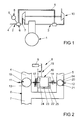
- FIG. 1 schematically shows an internal combustion engine 1 with an intake passage 2 and an exhaust pipe 3.
- the intake passage 2 has an intake passage 3, is sucked through the air from the environment.
- an exhaust passage 5 via a mixing valve 6 into the intake passage 2.
- the mixing valve 6 performs gas flows from the intake passage 4 and from the exhaust passage 5 to a common gas flow in a collecting channel 7 together.
- the gas flows in the mixing valve 6 can be controlled by a drive device 8 with a single electric servomotor 9.
- the internal combustion engine 1 has a turbocharger 10, which compresses a gas stream in the collecting channel 7 and the internal combustion engine 1 feeds.
- other components of the internal combustion engine 1 and the turbocharger 10, such as sensors, other valves and intercooler are not shown.
- FIG. 2 schematically shows the mixing valve 6 with the drive device 8 from FIG. 1 ,
- the mixing valve 6 has in the intake passage 4 and in the exhaust passage 5 respectively pivotable shafts 11, 12 arranged thereon with flaps 13, 14 for controlling the cross sections of the intake passage 4 and the exhaust passage 5.
- the drive means 8 has a transmission 15 with a differential gear sixteenth
- the only servo motor 9 drives the gear 15, which in turn drives the differential gear 16.
- the shafts 11, 12 and thus the flaps 13, 14 are driven.
- the flaps 13, 14 are also each biased by spring elements 17, 18 in a basic position. In the basic positions, the flaps 13, 14 abut against schematically represented stops 19, 20.
- the shafts 11, 12 are mounted in a housing, not shown, of the mixing valve 6.
- the housing also accommodates the servomotor 9 and the transmission 15 with the differential gear 16.
- the differential gear 16 has a directly driven by the gear 15 cage 22 in which a planet gear 23 is mounted.
- the planetary gear 23 is connected to two drive wheels 24, 25 engaged.
- the drive wheels 24, 25 are rotatably connected to the shafts 11, 12.
- the spring element 17 of the arranged in the intake passage 4 flap 13 has a greater spring stiffness than the spring element 18 of the arranged in the exhaust passage 5 flap 14.
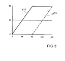
- FIG. 3 The movements of the flaps 13, 14 between a basic position and a relation to this rotated by 90 ° position over a set angle of 0 ° to 180 ° are in FIG. 3 shown.
- a14 the movement of the flap 14 arranged in the exhaust duct 5 and with a13 the movement of the flap 13 arranged in the intake duct 4 are identified.
Landscapes
- Engineering & Computer Science (AREA)
- Chemical & Material Sciences (AREA)
- Combustion & Propulsion (AREA)
- Mechanical Engineering (AREA)
- General Engineering & Computer Science (AREA)
- Exhaust-Gas Circulating Devices (AREA)
- Exhaust Silencers (AREA)
- Electrically Driven Valve-Operating Means (AREA)
- Mechanically-Actuated Valves (AREA)
- Multiple-Way Valves (AREA)
Abstract
Description
- Die Erfindung betrifft ein Mischventil einer Brennkraftmaschine eines Kraftfahrzeuges mit einer in einem Ansaugkanal angeordneten Klappe und einer in einem Abgaskanal angeordneten Klappe, mit drehbar gelagerten, die Klappen halternden Wellen, wobei der Ansaugkanal und der Abgaskanal in einen gemeinsamen Sammelkanal münden, und mit einer Antriebseinrichtung der Klappen, wobei die Antriebseinrichtung einen einzigen Stellmotor und ein Getriebe zur Ansteuerung der beiden Klappen aufweist.
- Solche Mischventile werden bei Abgasrückführungssystemen von Brennkraftmaschinen heutiger Kraftfahrzeuge häufig eingesetzt und sind aus der Praxis bekannt. Die Bewegungen der Klappen des Ansaugkanals und des Abgaskanals sind derart gesteuert, dass die im Abgaskanal angeordnete Klappe ausgehend von der ersten Stellung linear mit einem Ansteuersignal der Antriebseinrichtung öffnet. Die im Ansaugkanal angeordnete Klappe verharrt jedoch zunächst in der ersten Stellung und wird erst bewegt, wenn die Antriebseinrichtung um einen vorgesehenen Stellbereich angetrieben ist.
- Die Klappen sollen daher unabhängig voneinander angesteuert werden. Bei dem aus der Praxis bekannten Mischventil sind Stellhebel und Totgänge im Getriebe vorgesehen, welche die Klappen in vorgesehenen Stellbereichen von der Antriebseinrichtung entkoppeln. Dies führt jedoch zu einen hohen baulichen Aufwand des Getriebes.
- Der Erfindung liegt das Problem zugrunde, ein Mischventil der eingangs genannten Art so weiter zu bilden, dass es besonders einfach aufgebaut ist und eine Entkoppelung des Antriebs der Klappen ermöglicht.
- Dieses Problem wird erfindungsgemäß dadurch gelöst, dass das Getriebe ein Differentialgetriebe aufweist, und dass das Differentialgetriebe zwischen den beiden Wellen angeordnet ist.
- Durch diese Gestaltung wird jeweils die Welle angetrieben, die dem Antrieb den geringsten Widerstand entgegensetzt. Die Klappen sind erfindungsgemäß einfach dadurch entkoppelt, dass die eine Klappe mit einer etwas größeren Kraft in ihrer Ausgangslage gehalten ist oder an einem Anschlag anliegt. Hierdurch wird die Anzahl der beweglichen Bauteile besonders gering gehalten. Die Anzahl an Hardware und Softwarekomponenten des Mischventils lässt sich dank der Erfindung besonders gering halten. Das Mischventil ist daher besonders einfach aufgebaut. Bekannte Differentialgetriebe gestalten sich zudem besonders kompakt, so dass das Mischventil besonders kleine Abmessungen aufweist.
- Die Entkoppelung der Bewegungen der Klappen gestaltet sich gemäß einer anderen vorteilhaften Weiterbildung der Erfindung konstruktiv besonders einfach, wenn zumindest eine der Wellen mittels eines Federelementes in eine Grundstellung vorgespannt ist.
- Die Antriebseinrichtung erzeugt gemäß einer anderen vorteilhaften Weiterbildung der Erfindung eine aktive Schließbewegung der im Ansaugkanal angeordneten Klappe, wenn die in dem Ansaugkanal angeordnete Klappe in eine geöffnete Stellung gegen einen Anschlag vorgespannt ist. Vorzugsweise wird die Stellung der im Ansaugkanal angeordneten Klappe durch einen kontaktlosen Sensor erfasst.
- Zur Vereinfachung des Aufbaus des Mischventils trägt es gemäß einer anderen vorteilhaften Weiterbildung der Erfindung bei, wenn die in dem Abgaskanal angeordnete Klappe in die geschlossene Stellung gegen einen Anschlag vorgespannt ist.
- Die Überleitung des Antriebs der im Abgaskanal angeordneten Klappe zu der im Ansaugkanal angeordneten Klappe gestaltet sich gemäß einer anderen vorteilhaften Weiterbildung der Erfindung besonders einfach, wenn die im Abgaskanal angeordnete Klappe einen zweiten Anschlag in der geöffneten Stellung hat.
- Eine gezielte Steuerung der Klappen lässt sich gemäß einer anderen vorteilhaften Weiterbildung der Erfindung einfach erreichen, wenn ein die im Ansaugkanal angeordnete Klappe vorspannendes Federelement eine größere Federsteifigkeit aufweist als ein die im Abgaskanal angeordnete Klappe vorspannendes Federelement. Durch diese Gestaltung wird die im Abgaskanal angeordnete Klappe zunächst vollständig geöffnet. Erst anschließend wird die im Ansaugkanal angeordnete Klappe betätigt. Die im Abgaskanal angeordnete Klappe verbleibt vollständig in ihrer geöffneten Stellung.
- Das Verhältnis der maximalen Strömungen im Mischventil lässt sich gemäß einer anderen vorteilhaften Weiterbildung der Erfindung einfach einstellen, wenn der Abgaskanal einen größeren Strömungswiderstand aufweist als der Ansaugkanal.
- Die Erfindung lässt zahlreiche Ausführungsformen zu. Zur weiteren Verdeutlichung ihres Grundprinzips ist eine davon in der Zeichnung dargestellt und wird nachfolgend beschrieben. Diese zeigt in:
- Fig. 1
- schematisch eine Brennkraftmaschine mit einem Mischventil,
- Fig. 2
- der Aufbau des Mischventils in einer schematischen Darstellung,
- Fig. 3
- ein Diagramm der Schwenkbewegungen der Klappen in Abhängigkeit von Stellwinkel einer Antriebseinrichtung.
-
Figur 1 zeigt schematisch eine Brennkraftmaschine 1 mit einer Ansaugleitung 2 und einer Abgasleitung 3. Die Ansaugleitung 2 hat einen Ansaugkanal 3, über den Luft aus der Umgebung angesaugt wird. Von der Abgasleitung 3 führt ein Abgaskanal 5 über ein Mischventil 6 in die Ansaugleitung 2. Das Mischventil 6 führt Gasströme aus dem Ansaugkanal 4 und aus dem Abgaskanal 5 zu einem gemeinsamen Gasstrom in einem Sammelkanal 7 zusammen. Die Gasströme im Mischventil 6 lassen sich von einer Antriebseinrichtung 8 mit einem einzigen elektrischen Stellmotor 9 regeln. Weiterhin hat die Brennkraftmaschine 1 einen Turbolader 10, welcher einen Gasstrom im Sammelkanal 7 verdichtet und der Brennkraftmaschine 1 zuführt. Zur Vereinfachung der Zeichnung sind weitere Bauteile der Brennkraftmaschine 1 und des Turboladers 10, wie Sensoren, weitere Ventile und Ladeluftkühler nicht dargestellt. -
Figur 2 zeigt schematisch das Mischventil 6 mit der Antriebseinrichtung 8 ausFigur 1 . Das Mischventil 6 hat in dem Ansaugkanal 4 und in dem Abgaskanal 5 jeweils schwenkbare Wellen 11, 12 mit darauf angeordneten Klappen 13, 14 zur Steuerung der Querschnitte des Ansaugkanals 4 und des Abgaskanals 5. Die Antriebseinrichtung 8 hat ein Getriebe 15 mit einem Differentialgetriebe 16. Der einzige Stellmotor 9 treibt das Getriebe 15 an, welches wiederum das Differentialgetriebe 16 antreibt. Über das Differentialgetriebe 16 werden die Wellen 11, 12 und damit die Klappen 13, 14 angetrieben. Die Klappen 13, 14 sind zudem jeweils von Federelementen 17, 18 in eine Grundstellung vorgespannt. In den Grundstellungen liegen die Klappen 13, 14 an schematisch dargestellten Anschlägen 19, 20 an. Die Wellen 11, 12 sind in einem nicht dargestellten Gehäuse des Mischventils 6 gelagert. Das Gehäuse nimmt zudem den Stellmotor 9 und das Getriebe 15 mit dem Differentialgetriebe 16 auf. - Das Differentialgetriebe 16 hat einen unmittelbar von dem Getriebe 15 angetriebenen Käfig 22, in dem ein Umlaufrad 23 gelagert ist. Das Umlaufrad 23 steht mit zwei Antriebsrädern 24, 25 in Eingriff. Die Antriebsräder 24, 25 sind drehfest mit den Wellen 11, 12 verbunden.
- Das Federelement 17 der im Ansaugkanal 4 angeordneten Klappe 13 hat eine größere Federsteifigkeit als das Federelement 18 der im Abgaskanal 5 angeordneten Klappe 14. Damit wird bei einem beginnenden Betrieb des Stellmotors 9 zunächst die im Abgaskanal 5 angeordnete Klappe 14 angesteuert, bis sie gegen einen zweiten Anschlag 21 gelangt. Beim weiteren Betrieb der Antriebseinrichtung 8 wird die im Abgaskanal 5 angeordnete Klappe 14 an dem zweiten Anschlag 21 gehalten und die im Ansaugkanal 4 angeordnete Klappe 13 verstellt.
- Die Bewegungen der Klappen 13, 14 zwischen einer Grundstellung und einer gegenüber dieser um 90° verdrehten Stellung über einen Stellwinkel von 0° bis 180° sind in
Figur 3 dargestellt. Hierbei ist mit a14 die Bewegung der im Abgaskanal 5 angeordneten Klappe 14 und mit a13 die Bewegung der im Ansaugkanal 4 angeordneten Klappe 13 gekennzeichnet.
Claims (7)
- Mischventil (6) einer Brennkraftmaschine (1) eines Kraftfahrzeuges mit einer in einem Ansaugkanal (4) angeordneten Klappe (13) und einer in einem Abgaskanal (5) angeordneten Klappe (14), mit drehbar gelagerten, die Klappen (13, 14) halternden Wellen (11, 12), wobei der Ansaugkanal (4) und der Abgaskanal (5) in einen gemeinsamen Sammelkanal (7) münden, und mit einer Antriebseinrichtung (8) der Klappen (13, 14), wobei die Antriebseinrichtung (8) einen einzigen Stellmotor (9) und ein Getriebe (15) zur Ansteuerung der beiden Klappen (13, 14) aufweist, dadurch gekennzeichnet, dass das Getriebe (15) ein Differentialgetriebe (16) aufweist und dass das Differentialgetriebe (16) zwischen den beiden Wellen (11, 12) angeordnet ist.
- Mischventil nach Anspruch 1, dadurch ge- kennzeichnet, dass zumindest eine der Wellen mittels eines Federelementes in eine Grundstellung vorgespannt ist.
- Mischventil nach Anspruch 2, dadurch ge- kennzeichnet, dass die in dem Ansaugkanal angeordnete Klappe in eine geöffnete Stellung gegen einen Anschlag vorgespannt ist.
- Mischventil nach Anspruch 2 oder 3, dadurch gekennzeichnet, dass die in dem Abgaskanal angeordnete Klappe in die geschlossene Stellung gegen einen Anschlag vorgespannt ist.
- Mischventil nach Anspruch 4, dadurch gekennzeichnet, dass die im Abgaskanal angeordnete Klappe einen zweiten Anschlag in der geöffneten Stellung hat.
- Mischventil nach Anspruch 2, dadurch ge- kennzeichnet, dass ein die im Ansaugkanal angeordnete Klappe vorspannendes Federelement eine größere Federsteifigkeit aufweist als ein die im Abgaskanal angeordnete Klappe vorspannendes Federelement.
- Mischventil nach einem der Ansprüche 1 bis 6, da- durch gekennzeichnet, dass der Abgaskanal einen größeren Strömungswiderstand aufweist als der Ansaugkanal.
Priority Applications (4)
| Application Number | Priority Date | Filing Date | Title |
|---|---|---|---|
| EP13464011.9A EP2843223B1 (de) | 2013-09-02 | 2013-09-02 | Mischventil einer Brennkraftmaschine |
| US14/915,846 US9856832B2 (en) | 2013-09-02 | 2014-07-23 | Mixer valve of an internal combustion engine |
| CN201480048160.1A CN105829693B (zh) | 2013-09-02 | 2014-07-23 | 内燃机的组合阀 |
| PCT/EP2014/065800 WO2015028207A1 (de) | 2013-09-02 | 2014-07-23 | Mischventil einer brennkraftmaschine |
Applications Claiming Priority (1)
| Application Number | Priority Date | Filing Date | Title |
|---|---|---|---|
| EP13464011.9A EP2843223B1 (de) | 2013-09-02 | 2013-09-02 | Mischventil einer Brennkraftmaschine |
Publications (2)
| Publication Number | Publication Date |
|---|---|
| EP2843223A1 true EP2843223A1 (de) | 2015-03-04 |
| EP2843223B1 EP2843223B1 (de) | 2017-02-01 |
Family
ID=49354615
Family Applications (1)
| Application Number | Title | Priority Date | Filing Date |
|---|---|---|---|
| EP13464011.9A Not-in-force EP2843223B1 (de) | 2013-09-02 | 2013-09-02 | Mischventil einer Brennkraftmaschine |
Country Status (4)
| Country | Link |
|---|---|
| US (1) | US9856832B2 (de) |
| EP (1) | EP2843223B1 (de) |
| CN (1) | CN105829693B (de) |
| WO (1) | WO2015028207A1 (de) |
Citations (4)
| Publication number | Priority date | Publication date | Assignee | Title |
|---|---|---|---|---|
| US20050241702A1 (en) * | 2004-03-26 | 2005-11-03 | Stt Emtec Ab | Valve device |
| US20060283430A1 (en) * | 2005-06-17 | 2006-12-21 | Caterpillar Inc. | Throttle and recirculation valves having a common planetary drive |
| DE102008030785A1 (de) * | 2008-06-28 | 2009-12-31 | Pierburg Gmbh | Abgasrückführvorrichtung für eine Verbrennungskraftmaschine |
| DE102012203156A1 (de) * | 2012-02-29 | 2013-08-29 | Continental Automotive Gmbh | Mischventil einer Brennkraftmaschine |
Family Cites Families (8)
| Publication number | Priority date | Publication date | Assignee | Title |
|---|---|---|---|---|
| DE1771821U (de) | 1957-06-14 | 1958-08-07 | Radiologie Cie Gle | Mechanische betaetigungsvorrichtung fuer mehrere absperrorgane. |
| FR2900455B1 (fr) * | 2006-04-26 | 2008-07-04 | Valeo Sys Controle Moteur Sas | Vanne a deux papillons actionnes par un moteur commun |
| FR2926114B1 (fr) * | 2008-01-03 | 2012-12-14 | Valeo Sys Controle Moteur Sas | Boucle egr d'un moteur a combustion interne d'un vehicule automobile |
| JP4730447B2 (ja) * | 2009-02-18 | 2011-07-20 | 株式会社デンソー | 低圧egr装置 |
| WO2011024211A1 (ja) * | 2009-08-24 | 2011-03-03 | 三菱電機株式会社 | バルブ開閉機構 |
| JP5287953B2 (ja) * | 2011-04-27 | 2013-09-11 | 株式会社デンソー | 低圧egr装置 |
| US9587565B2 (en) * | 2011-06-17 | 2017-03-07 | Caterpillar Inc. | Valve stop for engine with exhaust gas recirculation |
| FR2979409B1 (fr) * | 2011-08-23 | 2013-08-23 | Valeo Sys Controle Moteur Sas | Vanne trois-voies a deux obturateurs et detection de course, notamment pour circuit d'admission de moteur d'automobile |
-
2013
- 2013-09-02 EP EP13464011.9A patent/EP2843223B1/de not_active Not-in-force
-
2014
- 2014-07-23 US US14/915,846 patent/US9856832B2/en active Active
- 2014-07-23 WO PCT/EP2014/065800 patent/WO2015028207A1/de not_active Ceased
- 2014-07-23 CN CN201480048160.1A patent/CN105829693B/zh active Active
Patent Citations (4)
| Publication number | Priority date | Publication date | Assignee | Title |
|---|---|---|---|---|
| US20050241702A1 (en) * | 2004-03-26 | 2005-11-03 | Stt Emtec Ab | Valve device |
| US20060283430A1 (en) * | 2005-06-17 | 2006-12-21 | Caterpillar Inc. | Throttle and recirculation valves having a common planetary drive |
| DE102008030785A1 (de) * | 2008-06-28 | 2009-12-31 | Pierburg Gmbh | Abgasrückführvorrichtung für eine Verbrennungskraftmaschine |
| DE102012203156A1 (de) * | 2012-02-29 | 2013-08-29 | Continental Automotive Gmbh | Mischventil einer Brennkraftmaschine |
Also Published As
| Publication number | Publication date |
|---|---|
| WO2015028207A1 (de) | 2015-03-05 |
| CN105829693B (zh) | 2019-06-21 |
| CN105829693A (zh) | 2016-08-03 |
| US9856832B2 (en) | 2018-01-02 |
| US20160195043A1 (en) | 2016-07-07 |
| EP2843223B1 (de) | 2017-02-01 |
Similar Documents
| Publication | Publication Date | Title |
|---|---|---|
| DE102009016597B4 (de) | Abgasklappenantrieb für ein Kraftfahrzeug | |
| DE102007021404B4 (de) | Abgasüberbrückungsventil-Fernverbindung | |
| DE60008673T2 (de) | Abgasrückführungsvorrichtung für eine Brennkraftmaschine | |
| DE102015215732A1 (de) | Steller zum Verstellen eines Stellorgans | |
| DE102008046596A1 (de) | Frischluftanlage | |
| EP2180167A1 (de) | Abgasklappenantrieb für ein Kraftfahrzeug | |
| EP2820284B1 (de) | Mischventil einer brennkraftmaschine | |
| DE102007025128A1 (de) | Ladeeinrichtung | |
| DE102014116974A1 (de) | EGR-Steuerventilvorrichtung | |
| EP2662556B1 (de) | Mischventil einer Brennkraftmaschine | |
| DE102005002266A1 (de) | Abgasrückführsystem für eine Brennkraftmaschine | |
| DE102010020709B4 (de) | Steuereinrichtung für eine turboaufgeladene Verbrennungskraftmaschine | |
| WO2013149896A1 (de) | Mischventil einer brennkraftmaschine eines kraftfahrzeuges | |
| DE102010050668A1 (de) | Ventileinrichtung | |
| EP2843223B1 (de) | Mischventil einer Brennkraftmaschine | |
| EP2623765A1 (de) | Abgassteuerungseinrichtung für eine Brennkraftmaschine | |
| DE60100768T2 (de) | Abgasrückführvorrichtung für eine Brennkraftmaschine | |
| WO2013156373A1 (de) | Mischventil einer brennkraftmaschine eines kraftfahrzeuges | |
| DE102010000688A1 (de) | Getriebeanordnung sowie Abgasturbolader | |
| WO2015014660A1 (de) | Einrichtung zur steuerung eines in einem ansaugkanal einer brennkraftmaschine angeordneten ladeluftkühlers und verfahren zum betrieb einer solchen einrichtung | |
| DE102009041963A1 (de) | Stellvorrichtung und Kopplungseinrichtung | |
| DE102010050256A1 (de) | Bauelement für eine Brennkraftmaschine und eine solche Brennkraftmaschine mit einer Abgasrückführleitung und einem Abgasrückführventil | |
| DE102008030785B4 (de) | Abgasrückführvorrichtung für eine Verbrennungskraftmaschine | |
| DE202007018936U1 (de) | Abgaseinrichtung eines Verbrennungsmotors mit einer auf einer Welle schwenkbar gelagerten Klappe | |
| DE102019219399A1 (de) | Ventilklappe zur Steuerung eines Fluiddurchflusses durch einen Strömungskanal und Ventil |
Legal Events
| Date | Code | Title | Description |
|---|---|---|---|
| 17P | Request for examination filed |
Effective date: 20130902 |
|
| AK | Designated contracting states |
Kind code of ref document: A1 Designated state(s): AL AT BE BG CH CY CZ DE DK EE ES FI FR GB GR HR HU IE IS IT LI LT LU LV MC MK MT NL NO PL PT RO RS SE SI SK SM TR |
|
| AX | Request for extension of the european patent |
Extension state: BA ME |
|
| PUAI | Public reference made under article 153(3) epc to a published international application that has entered the european phase |
Free format text: ORIGINAL CODE: 0009012 |
|
| R17P | Request for examination filed (corrected) |
Effective date: 20150904 |
|
| RBV | Designated contracting states (corrected) |
Designated state(s): AL AT BE BG CH CY CZ DE DK EE ES FI FR GB GR HR HU IE IS IT LI LT LU LV MC MK MT NL NO PL PT RO RS SE SI SK SM TR |
|
| REG | Reference to a national code |
Ref country code: DE Ref legal event code: R079 Ref document number: 502013006236 Country of ref document: DE Free format text: PREVIOUS MAIN CLASS: F02M0025070000 Ipc: F02M0026000000 |
|
| GRAP | Despatch of communication of intention to grant a patent |
Free format text: ORIGINAL CODE: EPIDOSNIGR1 |
|
| RIC1 | Information provided on ipc code assigned before grant |
Ipc: F02M 26/52 20160101ALI20160801BHEP Ipc: F02M 26/51 20160101ALI20160801BHEP Ipc: F02M 26/00 20160101AFI20160801BHEP Ipc: F02M 26/21 20160101ALI20160801BHEP Ipc: F02M 26/54 20160101ALI20160801BHEP Ipc: F02M 26/70 20160101ALI20160801BHEP |
|
| INTG | Intention to grant announced |
Effective date: 20160907 |
|
| GRAS | Grant fee paid |
Free format text: ORIGINAL CODE: EPIDOSNIGR3 |
|
| GRAA | (expected) grant |
Free format text: ORIGINAL CODE: 0009210 |
|
| AK | Designated contracting states |
Kind code of ref document: B1 Designated state(s): AL AT BE BG CH CY CZ DE DK EE ES FI FR GB GR HR HU IE IS IT LI LT LU LV MC MK MT NL NO PL PT RO RS SE SI SK SM TR |
|
| REG | Reference to a national code |
Ref country code: GB Ref legal event code: FG4D Free format text: NOT ENGLISH |
|
| REG | Reference to a national code |
Ref country code: CH Ref legal event code: EP Ref country code: AT Ref legal event code: REF Ref document number: 865819 Country of ref document: AT Kind code of ref document: T Effective date: 20170215 |
|
| REG | Reference to a national code |
Ref country code: IE Ref legal event code: FG4D Free format text: LANGUAGE OF EP DOCUMENT: GERMAN |
|
| REG | Reference to a national code |
Ref country code: DE Ref legal event code: R096 Ref document number: 502013006236 Country of ref document: DE |
|
| REG | Reference to a national code |
Ref country code: NL Ref legal event code: MP Effective date: 20170201 |
|
| REG | Reference to a national code |
Ref country code: LT Ref legal event code: MG4D |
|
| PG25 | Lapsed in a contracting state [announced via postgrant information from national office to epo] |
Ref country code: FI Free format text: LAPSE BECAUSE OF FAILURE TO SUBMIT A TRANSLATION OF THE DESCRIPTION OR TO PAY THE FEE WITHIN THE PRESCRIBED TIME-LIMIT Effective date: 20170201 Ref country code: IS Free format text: LAPSE BECAUSE OF FAILURE TO SUBMIT A TRANSLATION OF THE DESCRIPTION OR TO PAY THE FEE WITHIN THE PRESCRIBED TIME-LIMIT Effective date: 20170601 Ref country code: GR Free format text: LAPSE BECAUSE OF FAILURE TO SUBMIT A TRANSLATION OF THE DESCRIPTION OR TO PAY THE FEE WITHIN THE PRESCRIBED TIME-LIMIT Effective date: 20170502 Ref country code: LT Free format text: LAPSE BECAUSE OF FAILURE TO SUBMIT A TRANSLATION OF THE DESCRIPTION OR TO PAY THE FEE WITHIN THE PRESCRIBED TIME-LIMIT Effective date: 20170201 Ref country code: NO Free format text: LAPSE BECAUSE OF FAILURE TO SUBMIT A TRANSLATION OF THE DESCRIPTION OR TO PAY THE FEE WITHIN THE PRESCRIBED TIME-LIMIT Effective date: 20170501 Ref country code: HR Free format text: LAPSE BECAUSE OF FAILURE TO SUBMIT A TRANSLATION OF THE DESCRIPTION OR TO PAY THE FEE WITHIN THE PRESCRIBED TIME-LIMIT Effective date: 20170201 |
|
| PG25 | Lapsed in a contracting state [announced via postgrant information from national office to epo] |
Ref country code: ES Free format text: LAPSE BECAUSE OF FAILURE TO SUBMIT A TRANSLATION OF THE DESCRIPTION OR TO PAY THE FEE WITHIN THE PRESCRIBED TIME-LIMIT Effective date: 20170201 Ref country code: SE Free format text: LAPSE BECAUSE OF FAILURE TO SUBMIT A TRANSLATION OF THE DESCRIPTION OR TO PAY THE FEE WITHIN THE PRESCRIBED TIME-LIMIT Effective date: 20170201 Ref country code: BG Free format text: LAPSE BECAUSE OF FAILURE TO SUBMIT A TRANSLATION OF THE DESCRIPTION OR TO PAY THE FEE WITHIN THE PRESCRIBED TIME-LIMIT Effective date: 20170501 Ref country code: PL Free format text: LAPSE BECAUSE OF FAILURE TO SUBMIT A TRANSLATION OF THE DESCRIPTION OR TO PAY THE FEE WITHIN THE PRESCRIBED TIME-LIMIT Effective date: 20170201 Ref country code: PT Free format text: LAPSE BECAUSE OF FAILURE TO SUBMIT A TRANSLATION OF THE DESCRIPTION OR TO PAY THE FEE WITHIN THE PRESCRIBED TIME-LIMIT Effective date: 20170601 Ref country code: NL Free format text: LAPSE BECAUSE OF FAILURE TO SUBMIT A TRANSLATION OF THE DESCRIPTION OR TO PAY THE FEE WITHIN THE PRESCRIBED TIME-LIMIT Effective date: 20170201 Ref country code: LV Free format text: LAPSE BECAUSE OF FAILURE TO SUBMIT A TRANSLATION OF THE DESCRIPTION OR TO PAY THE FEE WITHIN THE PRESCRIBED TIME-LIMIT Effective date: 20170201 Ref country code: RS Free format text: LAPSE BECAUSE OF FAILURE TO SUBMIT A TRANSLATION OF THE DESCRIPTION OR TO PAY THE FEE WITHIN THE PRESCRIBED TIME-LIMIT Effective date: 20170201 |
|
| REG | Reference to a national code |
Ref country code: FR Ref legal event code: PLFP Year of fee payment: 5 |
|
| PG25 | Lapsed in a contracting state [announced via postgrant information from national office to epo] |
Ref country code: SK Free format text: LAPSE BECAUSE OF FAILURE TO SUBMIT A TRANSLATION OF THE DESCRIPTION OR TO PAY THE FEE WITHIN THE PRESCRIBED TIME-LIMIT Effective date: 20170201 Ref country code: RO Free format text: LAPSE BECAUSE OF FAILURE TO SUBMIT A TRANSLATION OF THE DESCRIPTION OR TO PAY THE FEE WITHIN THE PRESCRIBED TIME-LIMIT Effective date: 20170201 Ref country code: EE Free format text: LAPSE BECAUSE OF FAILURE TO SUBMIT A TRANSLATION OF THE DESCRIPTION OR TO PAY THE FEE WITHIN THE PRESCRIBED TIME-LIMIT Effective date: 20170201 Ref country code: CZ Free format text: LAPSE BECAUSE OF FAILURE TO SUBMIT A TRANSLATION OF THE DESCRIPTION OR TO PAY THE FEE WITHIN THE PRESCRIBED TIME-LIMIT Effective date: 20170201 |
|
| REG | Reference to a national code |
Ref country code: DE Ref legal event code: R097 Ref document number: 502013006236 Country of ref document: DE |
|
| PG25 | Lapsed in a contracting state [announced via postgrant information from national office to epo] |
Ref country code: DK Free format text: LAPSE BECAUSE OF FAILURE TO SUBMIT A TRANSLATION OF THE DESCRIPTION OR TO PAY THE FEE WITHIN THE PRESCRIBED TIME-LIMIT Effective date: 20170201 Ref country code: SM Free format text: LAPSE BECAUSE OF FAILURE TO SUBMIT A TRANSLATION OF THE DESCRIPTION OR TO PAY THE FEE WITHIN THE PRESCRIBED TIME-LIMIT Effective date: 20170201 |
|
| PLBE | No opposition filed within time limit |
Free format text: ORIGINAL CODE: 0009261 |
|
| STAA | Information on the status of an ep patent application or granted ep patent |
Free format text: STATUS: NO OPPOSITION FILED WITHIN TIME LIMIT |
|
| 26N | No opposition filed |
Effective date: 20171103 |
|
| PG25 | Lapsed in a contracting state [announced via postgrant information from national office to epo] |
Ref country code: SI Free format text: LAPSE BECAUSE OF FAILURE TO SUBMIT A TRANSLATION OF THE DESCRIPTION OR TO PAY THE FEE WITHIN THE PRESCRIBED TIME-LIMIT Effective date: 20170201 |
|
| REG | Reference to a national code |
Ref country code: CH Ref legal event code: PL |
|
| GBPC | Gb: european patent ceased through non-payment of renewal fee |
Effective date: 20170902 |
|
| PG25 | Lapsed in a contracting state [announced via postgrant information from national office to epo] |
Ref country code: MC Free format text: LAPSE BECAUSE OF FAILURE TO SUBMIT A TRANSLATION OF THE DESCRIPTION OR TO PAY THE FEE WITHIN THE PRESCRIBED TIME-LIMIT Effective date: 20170201 |
|
| REG | Reference to a national code |
Ref country code: IE Ref legal event code: MM4A |
|
| REG | Reference to a national code |
Ref country code: BE Ref legal event code: MM Effective date: 20170930 |
|
| PG25 | Lapsed in a contracting state [announced via postgrant information from national office to epo] |
Ref country code: LU Free format text: LAPSE BECAUSE OF NON-PAYMENT OF DUE FEES Effective date: 20170902 |
|
| PG25 | Lapsed in a contracting state [announced via postgrant information from national office to epo] |
Ref country code: GB Free format text: LAPSE BECAUSE OF NON-PAYMENT OF DUE FEES Effective date: 20170902 Ref country code: CH Free format text: LAPSE BECAUSE OF NON-PAYMENT OF DUE FEES Effective date: 20170930 Ref country code: IE Free format text: LAPSE BECAUSE OF NON-PAYMENT OF DUE FEES Effective date: 20170902 Ref country code: LI Free format text: LAPSE BECAUSE OF NON-PAYMENT OF DUE FEES Effective date: 20170930 |
|
| PG25 | Lapsed in a contracting state [announced via postgrant information from national office to epo] |
Ref country code: BE Free format text: LAPSE BECAUSE OF NON-PAYMENT OF DUE FEES Effective date: 20170930 |
|
| REG | Reference to a national code |
Ref country code: FR Ref legal event code: PLFP Year of fee payment: 6 |
|
| PG25 | Lapsed in a contracting state [announced via postgrant information from national office to epo] |
Ref country code: MT Free format text: LAPSE BECAUSE OF FAILURE TO SUBMIT A TRANSLATION OF THE DESCRIPTION OR TO PAY THE FEE WITHIN THE PRESCRIBED TIME-LIMIT Effective date: 20170201 |
|
| PG25 | Lapsed in a contracting state [announced via postgrant information from national office to epo] |
Ref country code: HU Free format text: LAPSE BECAUSE OF FAILURE TO SUBMIT A TRANSLATION OF THE DESCRIPTION OR TO PAY THE FEE WITHIN THE PRESCRIBED TIME-LIMIT; INVALID AB INITIO Effective date: 20130902 |
|
| PG25 | Lapsed in a contracting state [announced via postgrant information from national office to epo] |
Ref country code: CY Free format text: LAPSE BECAUSE OF FAILURE TO SUBMIT A TRANSLATION OF THE DESCRIPTION OR TO PAY THE FEE WITHIN THE PRESCRIBED TIME-LIMIT Effective date: 20170201 |
|
| PGFP | Annual fee paid to national office [announced via postgrant information from national office to epo] |
Ref country code: IT Payment date: 20190925 Year of fee payment: 7 Ref country code: FR Payment date: 20190927 Year of fee payment: 7 |
|
| REG | Reference to a national code |
Ref country code: AT Ref legal event code: MM01 Ref document number: 865819 Country of ref document: AT Kind code of ref document: T Effective date: 20180902 |
|
| PG25 | Lapsed in a contracting state [announced via postgrant information from national office to epo] |
Ref country code: MK Free format text: LAPSE BECAUSE OF FAILURE TO SUBMIT A TRANSLATION OF THE DESCRIPTION OR TO PAY THE FEE WITHIN THE PRESCRIBED TIME-LIMIT Effective date: 20170201 |
|
| PG25 | Lapsed in a contracting state [announced via postgrant information from national office to epo] |
Ref country code: AT Free format text: LAPSE BECAUSE OF NON-PAYMENT OF DUE FEES Effective date: 20180902 |
|
| PGFP | Annual fee paid to national office [announced via postgrant information from national office to epo] |
Ref country code: DE Payment date: 20190930 Year of fee payment: 7 |
|
| PG25 | Lapsed in a contracting state [announced via postgrant information from national office to epo] |
Ref country code: TR Free format text: LAPSE BECAUSE OF FAILURE TO SUBMIT A TRANSLATION OF THE DESCRIPTION OR TO PAY THE FEE WITHIN THE PRESCRIBED TIME-LIMIT Effective date: 20170201 |
|
| REG | Reference to a national code |
Ref country code: DE Ref legal event code: R081 Ref document number: 502013006236 Country of ref document: DE Owner name: VITESCO TECHNOLOGIES GMBH, DE Free format text: FORMER OWNER: CONTINENTAL AUTOMOTIVE GMBH, 30165 HANNOVER, DE |
|
| PG25 | Lapsed in a contracting state [announced via postgrant information from national office to epo] |
Ref country code: AL Free format text: LAPSE BECAUSE OF FAILURE TO SUBMIT A TRANSLATION OF THE DESCRIPTION OR TO PAY THE FEE WITHIN THE PRESCRIBED TIME-LIMIT Effective date: 20170201 |
|
| REG | Reference to a national code |
Ref country code: DE Ref legal event code: R119 Ref document number: 502013006236 Country of ref document: DE |
|
| PG25 | Lapsed in a contracting state [announced via postgrant information from national office to epo] |
Ref country code: FR Free format text: LAPSE BECAUSE OF NON-PAYMENT OF DUE FEES Effective date: 20200930 Ref country code: DE Free format text: LAPSE BECAUSE OF NON-PAYMENT OF DUE FEES Effective date: 20210401 |
|
| PG25 | Lapsed in a contracting state [announced via postgrant information from national office to epo] |
Ref country code: IT Free format text: LAPSE BECAUSE OF NON-PAYMENT OF DUE FEES Effective date: 20200902 |