EP2842802B1 - Rückenlehne für einem Fahrzeugsitz - Google Patents
Rückenlehne für einem Fahrzeugsitz Download PDFInfo
- Publication number
- EP2842802B1 EP2842802B1 EP13181842.9A EP13181842A EP2842802B1 EP 2842802 B1 EP2842802 B1 EP 2842802B1 EP 13181842 A EP13181842 A EP 13181842A EP 2842802 B1 EP2842802 B1 EP 2842802B1
- Authority
- EP
- European Patent Office
- Prior art keywords
- air bag
- back rest
- support member
- deployment
- trim cover
- Prior art date
- Legal status (The legal status is an assumption and is not a legal conclusion. Google has not performed a legal analysis and makes no representation as to the accuracy of the status listed.)
- Active
Links
- 239000000463 material Substances 0.000 claims description 21
- 238000000034 method Methods 0.000 claims description 7
- 239000002131 composite material Substances 0.000 claims description 4
- 229920001169 thermoplastic Polymers 0.000 claims description 4
- 239000004743 Polypropylene Substances 0.000 claims description 3
- -1 polypropylene Polymers 0.000 claims description 3
- 229920001155 polypropylene Polymers 0.000 claims description 3
- OKTJSMMVPCPJKN-UHFFFAOYSA-N Carbon Chemical compound [C] OKTJSMMVPCPJKN-UHFFFAOYSA-N 0.000 claims description 2
- 239000004952 Polyamide Substances 0.000 claims description 2
- 239000004676 acrylonitrile butadiene styrene Substances 0.000 claims description 2
- 229910052799 carbon Inorganic materials 0.000 claims description 2
- 239000000835 fiber Substances 0.000 claims description 2
- 239000000203 mixture Substances 0.000 claims description 2
- 229920002647 polyamide Polymers 0.000 claims description 2
- 229920002635 polyurethane Polymers 0.000 claims description 2
- 239000004814 polyurethane Substances 0.000 claims description 2
- 229920000122 acrylonitrile butadiene styrene Polymers 0.000 claims 1
- 239000006260 foam Substances 0.000 description 6
- 238000006073 displacement reaction Methods 0.000 description 3
- 230000001419 dependent effect Effects 0.000 description 2
- 229920000049 Carbon (fiber) Polymers 0.000 description 1
- 229910000831 Steel Inorganic materials 0.000 description 1
- 239000000853 adhesive Substances 0.000 description 1
- 230000001070 adhesive effect Effects 0.000 description 1
- 239000004917 carbon fiber Substances 0.000 description 1
- 230000002349 favourable effect Effects 0.000 description 1
- 239000002184 metal Substances 0.000 description 1
- VNWKTOKETHGBQD-UHFFFAOYSA-N methane Chemical compound C VNWKTOKETHGBQD-UHFFFAOYSA-N 0.000 description 1
- 239000011208 reinforced composite material Substances 0.000 description 1
- 230000002441 reversible effect Effects 0.000 description 1
- 239000010959 steel Substances 0.000 description 1
- 239000012815 thermoplastic material Substances 0.000 description 1
- 238000003466 welding Methods 0.000 description 1
Images

Classifications
-
- B—PERFORMING OPERATIONS; TRANSPORTING
- B60—VEHICLES IN GENERAL
- B60N—SEATS SPECIALLY ADAPTED FOR VEHICLES; VEHICLE PASSENGER ACCOMMODATION NOT OTHERWISE PROVIDED FOR
- B60N2/00—Seats specially adapted for vehicles; Arrangement or mounting of seats in vehicles
- B60N2/58—Seat coverings
- B60N2/5816—Seat coverings attachments thereof
-
- B—PERFORMING OPERATIONS; TRANSPORTING
- B60—VEHICLES IN GENERAL
- B60N—SEATS SPECIALLY ADAPTED FOR VEHICLES; VEHICLE PASSENGER ACCOMMODATION NOT OTHERWISE PROVIDED FOR
- B60N2/00—Seats specially adapted for vehicles; Arrangement or mounting of seats in vehicles
- B60N2/58—Seat coverings
- B60N2/60—Removable protective coverings
- B60N2/6009—Removable protective coverings covering more than only the seat
-
- B—PERFORMING OPERATIONS; TRANSPORTING
- B60—VEHICLES IN GENERAL
- B60N—SEATS SPECIALLY ADAPTED FOR VEHICLES; VEHICLE PASSENGER ACCOMMODATION NOT OTHERWISE PROVIDED FOR
- B60N2/00—Seats specially adapted for vehicles; Arrangement or mounting of seats in vehicles
- B60N2/68—Seat frames
-
- B—PERFORMING OPERATIONS; TRANSPORTING
- B60—VEHICLES IN GENERAL
- B60N—SEATS SPECIALLY ADAPTED FOR VEHICLES; VEHICLE PASSENGER ACCOMMODATION NOT OTHERWISE PROVIDED FOR
- B60N2/00—Seats specially adapted for vehicles; Arrangement or mounting of seats in vehicles
- B60N2/68—Seat frames
- B60N2/686—Panel like structures
-
- B—PERFORMING OPERATIONS; TRANSPORTING
- B60—VEHICLES IN GENERAL
- B60R—VEHICLES, VEHICLE FITTINGS, OR VEHICLE PARTS, NOT OTHERWISE PROVIDED FOR
- B60R21/00—Arrangements or fittings on vehicles for protecting or preventing injuries to occupants or pedestrians in case of accidents or other traffic risks
- B60R21/02—Occupant safety arrangements or fittings, e.g. crash pads
- B60R21/16—Inflatable occupant restraints or confinements designed to inflate upon impact or impending impact, e.g. air bags
- B60R21/20—Arrangements for storing inflatable members in their non-use or deflated condition; Arrangement or mounting of air bag modules or components
- B60R21/207—Arrangements for storing inflatable members in their non-use or deflated condition; Arrangement or mounting of air bag modules or components in vehicle seats
-
- B—PERFORMING OPERATIONS; TRANSPORTING
- B60—VEHICLES IN GENERAL
- B60N—SEATS SPECIALLY ADAPTED FOR VEHICLES; VEHICLE PASSENGER ACCOMMODATION NOT OTHERWISE PROVIDED FOR
- B60N2/00—Seats specially adapted for vehicles; Arrangement or mounting of seats in vehicles
- B60N2/58—Seat coverings
- B60N2002/5808—Seat coverings comprising opening zones for airbags
-
- B—PERFORMING OPERATIONS; TRANSPORTING
- B60—VEHICLES IN GENERAL
- B60R—VEHICLES, VEHICLE FITTINGS, OR VEHICLE PARTS, NOT OTHERWISE PROVIDED FOR
- B60R21/00—Arrangements or fittings on vehicles for protecting or preventing injuries to occupants or pedestrians in case of accidents or other traffic risks
- B60R21/02—Occupant safety arrangements or fittings, e.g. crash pads
- B60R21/16—Inflatable occupant restraints or confinements designed to inflate upon impact or impending impact, e.g. air bags
- B60R21/20—Arrangements for storing inflatable members in their non-use or deflated condition; Arrangement or mounting of air bag modules or components
- B60R21/207—Arrangements for storing inflatable members in their non-use or deflated condition; Arrangement or mounting of air bag modules or components in vehicle seats
- B60R2021/2076—Removable covers with tear seams
Definitions
- a vehicle seat comprising an air bag module, a trim and a support member for the trim.
- the support member is adapted to be displaced with the air bag of the air bag module during deployment.
- Vehicle seats in some vehicles have been provided with air bag modules during recent years to provide for additional protection for the passengers.
- Some vehicle seats have air bag modules incorporated in the back rest to protect the passenger from a side impact for example.
- Ordinary back rests on vehicle seats tend to have plenty of space to incorporate an air bag module.
- vehicle seats with slim design back rests have been introduced.
- Some back rests are specifically designed to provide the back seat passengers with an improved leg space.
- the back seat of an automobile tends to have a limit the amount of available leg space for the back seat passengers.
- automobile manufacturers have started to reduce the thickness of the back rest especially on the front row vehicle seats e.g. the driver seat. With reduced thickness, i.e. slim back rests, problems have arisen with the amount of available space inside of the back rests.
- Air bag modules generally require not only a determined amount of available space but also a determined escape route for the air bag when the air bag deploys. The escape route, i.e.
- the German patent application No. DE 10 2008 053 080 A1 discloses a vehicle seat having a width adjustable seatback comprising an integrated airbag module.
- the airbag module is enclosed by a seatback frame and a support element.
- the support element is designed to flex toward the middle of the seatback when the airbag is deployed, such as to push the foamed part inwards to some extent. It is mentioned that the support element can bend or rotate toward the center of the seat.
- the front portion of the support element is mechanically engaged to the front portion of the seatback frame prior to airbag deployment. This engagement unlocks upon airbag deployment and a tear seam in the trim cover breaks open.
- the US patent application 2006/0163850 A1 discloses a back rest for a vehicle seat comprising an air bag arrangement.
- the air bag is intended to be deployed between the trim cover and the back portion of the vehicle seat not to rupture the trim cover.
- the object is at least partly met by a back rest for a vehicle seat according to claim 1.
- the back rest has a back side and a front side.
- the back rest comprises a seat frame, a back rest case adapted to cover at least a portion the back side of the back rest, a trim cover adapted to cover at least a portion of the front side of the back rest, and at least one air bag module having at least one air bag.
- the at least one air bag module has a main direction of deployment along which the at least one air bag is adapted to be deployed.
- the at least one air bag has an escape route during deployment between the trim cover and the seat back rest case to reach an inflated position.
- a support member is adapted to support the trim cover.
- the support member is preferably a trim list.
- the support member is positioned so as to intersect with the main direction of deployment of the at least one air bag module, and adapted to be displaced upon deployment of the at least one air bag. The displacement is done by the inflation of the air bag and thus the pressure imparted to the support member by the air bag during the inflation.
- the support member is adapted to stretch the trim cover, or to retain the trim cover in a favoured position.
- the air bag module is preferably positioned on the side of the seat frame, preferably the side closest to the A, B, or C - pillar of the vehicle, if the vehicle is an automobile.
- the support member is arranged to the seat frame.
- the support member can be arranged directly onto the seat frame or indirectly via an intermediate member.
- the air bag module can optionally be arranged to the seat frame directly or indirectly via an intermediate member.
- a portion of the trim cover can be arranged between the air bag module and the seat frame for example.
- the support member can be provided with an air bag receiving surface.
- the air bag receiving surface can be formed or shaped so as to receive the air bag during deployment in a favourable manner.
- the air bag receiving surface can be angled with respect to the main direction of deployment with an angle. If the angle of the air bag receiving surface is perpendicular or substantially perpendicular with respect to the main direction of deployment, the support member will receive a high level of force during impact with the deployed air bag. As the angle is reduced, e.g. to 80 degrees or less, the level of force will be reduced.
- the angle can be from 40- 130 degrees, preferably from 70-120 degrees.
- the air bag receiving surface should preferably be adapted to receive the air bag so it is readily displaced, permitting the air bag to be properly deployed.
- the support member is releaseably arranged to the seat frame and that the deployment of the air bag triggers the detachment of the support member to provide enough space for the air bag to inflate.
- detachment could be permanent, i.e. the support members breaks off preventing reattachment, or the support member can be reattachable to the seat frame.
- An example of a reattachable attachment arrangement is a snap on connection adapted to be detached for forces above a threshold level.
- the at least one air bag module is positioned between a portion of the trim cover and a portion of the seat back case. Such configuration would further secure that the air bag is readily deployed between the trim cover and the back rest case.
- the support member has an elongated form with a first and a second longitudinal side, and a first and a second transverse side. The support member is attached to the frame structure of the back rest along the first longitudinal side.
- the support member is provided with at least one weak point, or section, enabling the support member to be deformed when the air bag is deployed so as to at least partly displace the support member.
- the at least one weak point can be by means of geometry of the material and/or by at least one weakened section in the material.
- the at least one weak point can be formed or defined by a second material adapted to be deformed due to geometry of the material and/or by at least one weakened section in the material.
- the material can be selected to be flexible so as to permit the support member to be deformed, e.g. to bend.
- the second material can be selected to be more brittle causing the support member to break during inflation of the air bag so that the support member is displaced. In the latter case when the support member breaks, the displacement and deformation is permanent, i.e. non-reversible.
- the support member can be formed by a thermoplastic polymer such as polyamide, polypropylene, polyurethane, Acrylonitrile Butadiene Styrene (ABS), mixtures thereof, or the like. It can also be formed by reinforced thermoplastic polymers such as carbon fibre reinforced composites or the like.
- the present invention relates to a method for deploying an air bag of an air bag module according to claim 10.
- the air bag module is positioned in a back rest according to any one of the appended claims.
- the method comprises the steps of claim 10.
- the method can further comprise a step of displacing the back rest case and the support member of the back rest by the inflation of the air bag.
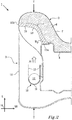
- Figure 1 shows a vehicle seat 1 comprising a seat section 2 and a back rest 3.
- the vehicle seat 1 is adapted to be positioned in a vehicle such as an automobile, an aero plane, a helicopter, a boat, a truck, a lorry or the like.
- the vehicle seat 1 comprises at least one air bag module 10.
- the air bag module 10 comprises an air bag (not shown in figure 1 ) adapted to be deployed in case of emergency such as a collision with another object.
- the air bag module 10 is positioned in the back rest 3 of the vehicle seat 1 and is arranged to the seat frame 4 via bolts, screws or any intermediate adapter.
- Typically such air bag module would be referred to as a side air bag, it is positioned on the side of the seat frame and intended to protect the side of the passenger during a side collision from the same side.
- the back rest 3 will hereafter be described in greater detail.
- the vehicle seat 1 has a height H, corresponding to the height of the vehicle, a length L, corresponding to the length of the vehicle and a width W, corresponding to the width of the vehicle.
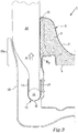
- FIG. 2 shows a schematic cross section of the back rest 3 along the line II-II.
- the vehicle seat 1 comprises a back rest 3, sometimes referred to as a slim back rest, i.e. the thickness, indicated in figure 2 with the arrows T-T, is relatively low.
- Figure 2 shows a seat frame 4 adapted to provide structural integrity to the back rest 3.
- the seat frame 4 is generally that part which is pivotally connected to the seat section 2.
- the seat frame 4 is made from sheet metal such as pressed plate steel, although other materials such as composite materials e.g. carbon fiber reinforced composite material is possible.
- a foam pad 6 is positioned adjacent the seat frame 4 to form a comfortable back rest structure for the passenger.
- the back rest 3 is further provided with a back rest case 16 adapted to cover the back side of the back rest 3.
- the back side of the back rest 3 is that side which is facing the rear passengers.
- the back rest case 16 is formed by a relatively rigid material, such as polypropylene or a composite material, and is designed to provide an appealing look, yet be a sturdy outer case to the back rest 3 of the vehicle seat 1.
- a trim cover 7 is covering the foam pad 6 and the seat frame 4.
- the trim cover 7 is generally covering the front side of the back rest 3, i.e. that side which the passenger seated in the vehicle seat 1 is leaning against.
- the support member 15 is illustrated in figure 1 with dashed lines.
- the support member 15 further braces the foam pad 6, although that is not a requirement.
- the trim cover 7 extends past the support member 15 and in behind the back rest case 16 into the interior of the back rest 3.
- the support member 15 is positioned at the side of the seat frame 4 and protrudes from the side of the seat frame 4 having a proximal side 15a and a distal side 15b with respect to the seat frame 4.
- the air bag module 10 has a housing 11 in which an air bag (not shown) is positioned in a folded manner.
- An inflator 12 comprising a pyrotechnic device or other gas generating device is also disposed within the housing 11 for rapidly inflating the air bag.
- Deflectors 13 are arranged to direct the deployment of the air bag along a main direction of deployment A.
- the air bag module 10 is adapted to be deployed in response to a signal from a vehicle crash detecting system adapted to detect a crash or an imminent crash.
- the air bag module 10 is specifically adapted to protect passengers from a side impact hence it can be referred to as a side air bag module, although it may still be deployed before or during a front or rear collision.
- the air bag module 10 can be positioned between trim cover 7 and the back rest case 16 but on the side of the seat frame 4, i.e. not on the front or back side of the seat frame 4. In figure 2 it can however be noticed that the trim cover 7 ends just ahead of the air bag module 10.
- the air bag module 10 has a main direction of deployment A along which the air bag (not shown in figure 2 ) is intended to be deployed.
- the main direction of deployment A is substantially corresponding to the length L of the vehicle seat 1 and the vehicle.
- the main direction of deployment A is substantially directed towards the support member 15, but could be directed towards the back rest case 16 if desired.
- the main direction of deployment is directed towards the support member 15.
- the air bag of the air bag module 10 is thus propelled substantially directly towards the support member 15 during deployment.
- the support member 15 will be forced to a displaced position permitting the air bag to pass the support member 15 between the back case 16 and the trim cover 7 to be fully inflated.
- the support member 15 can be provided with at least one weak point Wp shown in figure 2 as an indent in the support member 15.
- the weak point Wp could however be formed in other manners such as forming a section of the support member 15 in another material.
- the at least one weak point is intended to define a portion or section on the support member 15 about which the support member 15 can pivot, deform, or in any other way be displaced to permit the deployment of the air bag module 10 to inflate the air bag.
- Similar at least one weak point can be arranged on the back rest case 16 to facilitate, or simplify, the deformation of the back rest case 16 during a deployment shown in figure 3 .
- the support member 15 stretches the trim cover 7 which in figure 2 is the near proximity of the back rest case 16 contacting the trim cover 7, providing a soft edge contact.
- the order of material would be the support member 15, the trim cover 7 which is in direct contact, i.e. adjacent, or in the proximity of the back rest cover 16.
- Figure 3 shows the cross section of figure 2 after the air bag module 10 has been deployed.
- Figure 3 shows a portion of the vehicle seat 1, the back rest 3, the seat frame 4, the foam pad 6, the trim cover 7, the air bag module 10, the housing 11, the air bag inflator 12, the deflectors 13, the back rest case 16 and a portion of an air bag 20.
- the air bag 20 has been inflated between the back rest case 16 and the trim cover 7, without tearing the trim cover 7 or without going through a specific trim seam, but simply by displacing the trim cover 7, and the foam pad 6 in the shown embodiment.
- the support member 15 has further been deformed to a position which permits the air bag 20 to be fully inflated, i.e. to a position in which the air bag 20 protects the passenger seated in the vehicle seat 1, or any other passenger in the vehicle dependent on the intended purpose of the air bag module 10 or the nature of the accident.
- the air bag 20 is inflated outside of the trim cover 7 and passes, i.e. escapes, between the back rest case 16 and the trim cover 7. A portion 16a of the back rest case 16 is further displaced to provide space for the air bag 20 to be fully inflated.
- the back rest case 16 nor the trim cover 7 are in the shown embodiment damaged beyond being reused by the deployment of the air bag module 10 due to the fact that the support member 15 and a portion of the back case 16 are displaced by the air bag 20 of the air bag module 10, thus providing the air bag 20 with space enough to be fully inflated.
- the support member 15 is displaced while the back case 16 is substantially not displaced, or not displaced at all.
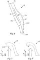
- FIG. 4 shows the support member 15 in greater detail.
- the support member 15 has a substantially elongated extension and comprises a first and a second longitudinal side 15a, 15b, a first and a second transverse side 15c, 15d.
- the first longitudinal side 15a is attached to the seat frame 4 by screws or other suitable attachment means such as adhesive, welding, bolts, rivets, mechanical snap on connection or the like.
- the first longitudinal side 15a is thus a proximal side to the seat frame 4, while the second longitudinal side 15b is the distal side with respect to the seat frame 4.
- the support member 15 has a passenger facing side 17, intended to be facing towards the passenger, and an air bag module facing side 18, intended to be facing substantially towards the air bag module 10.
- the exact form and shape of the support member 15 may vary.
- the passenger facing side 17 of the support member 15 is provided with a smooth shaped surface adapted to conform to the trim 7 facing the passenger and to support the foam pad 6 (shown in figure 2 ).
- An aspect of the support member 15 is that it interacts with the air bag of the air bag module after deployment to be displaced, in this case by being deformed, thus enabling the air bag of the air bag module to be deployed in a very advantageous manner.
- the support member 15 substantially pivots about the proximal side 15a while being displaced.
- a deformation line 25, indicated with dashed lines in figure 4 defines the line about which the support member 15 is intended to deform, or pivot, upon deployment of the air bag 20.
- the deformation line 25 is in the shown embodiment formed by a continuous groove 26.
- the continuous groove 26 has a material thickness of about 0.5 times the thickness of the surrounding material.
- the support member 15 can either break along the deformation line 25 upon deployment of the air bag 20 or simply bend around the deformation line 25 as shown in figure 3 for example.
- the deformation line 25 can be formed by a plurality of individual weak points forming a continuous line.
- the plurality of individual weak points can be a series of indents forming the deformation line.
- the indents could have the same or different form such as rectangular, squared, polygonal or circular form for example.
- the deformation line 25 could as an alternative, or in addition, be formed by a second material different from the material of the support member 15.
- the second material could be a flexible thermoplastic material adapted to bend or break at impact.
- the support member 15 has an air bag module facing side 18.
- the air bag module facing side 18 is adapted to receive the air bag 20 during deployment and can be positioned directly intersecting with the main direction of deployment, or not necessarily facing strictly towards the air bag module 10 but rather having an air bag receiving surface 18' adapted to receive and interact with the air bag 20 during deployment.
- Figure 5 shows a cross section of an embodiment of a support member 15, with a view along the height H, having an air bag receiving surface 18' being substantially perpendicular to the main direction of deployment A.
- the angle ⁇ which in figure 5 is substantially 90 degrees.
- the angle ⁇ can be from 40- 130 degrees, preferably from 70-120 degrees.
- Figure 6 shows a cross section of an embodiment of a support member 15, with a view along the height H, having an air bag receiving surface 18' having a concave form with respect to the main direction of deployment A.
- the cross sections shown in figures 5 and 6 can be similar along the whole length of the deformation line 25, or be representative for a section of the support member 15.
- a specially adapted receiving surface 18" can for example be formed only on 50 % along the full length of the support member 15, for example as indicated in figure 4 . Independently of the shape and form of the air bag receiving surface 18'.
- a back rest 3 of the disclosed kind comprises one or more support members 15.
- the vehicle seat 1 in the shown embodiment has only one support member 15 adapted to interact with an air bag module as described herein.
Landscapes
- Engineering & Computer Science (AREA)
- Mechanical Engineering (AREA)
- Aviation & Aerospace Engineering (AREA)
- Transportation (AREA)
- Seats For Vehicles (AREA)
- Air Bags (AREA)
Claims (11)
- Rückenlehne (3) für einen Fahrzeugsitz (1), wobei die Rückenlehne (3) eine Rückseite und eine Vorderseite aufweist, wobei die Rückenlehne (3) einen Sitzrahmen (4), ein Rückenlehnengehäuse (16), das dazu angepasst ist, mindestens einen Abschnitt der Rückseite der Rückenlehne (3) abzudecken, eine Verkleidungsabdeckung (7), die dazu angepasst ist, mindestens einen Abschnitt der Vorderseite der Rückenlehne (3) abzudecken, und mindestens ein Airbagmodul (10) mit mindestens einem Airbag (20), wobei das mindestens eine Airbagmodul (10) eine Hauptentfaltungsrichtung (A) aufweist, entlang der der mindestens eine Airbag (20) dazu angepasst ist, entfaltet zu werden,wobei der mindestens eine Airbag (20) während der Entfaltung einen Ausweichweg zwischen der Verkleidungsabdeckung (7) und dem Sitzrückenlehnengehäuse (16) aufweist, um eine aufgeblasene Position zu erreichen,wobei ein Stützelement (15) dazu ausgelegt ist, die Verkleidungsabdeckung (7) zu stützen, wobei das Stützelement (15) so angeordnet ist, dass es die Hauptentfaltungsrichtung (A) des mindestens einen Airbagmoduls (10) schneidet,das Stützelement (15) mindestens eine Schwachstelle (26) aufweist, an der das Stützelement (15) so angepasst ist, dass es verformt wird, wenn der Airbag (20) entfaltet wird, um das Stützelement (15) mindestens teilweise zu verschieben,dadurch gekennzeichnet, dassder mindestens eine Schwachpunkt (26) eine Verformungslinie (25) ist, um die sich das Stützelement (15) bei Entfaltung des Airbags (20) verformen oder schwenken soll, wobei die Verformungslinie durch eine durchgehende Rille (26) oder eine Reihe von Einkerbungen oder durch ein zweites Material, das aufgrund der Geometrie des Materials verformt werden kann, und/oder durch mindestens einen geschwächten Abschnitt im Material gebildet wird.
- Rückenlehne (3) gemäß Anspruch 1, wobei das Stützelement (15) am Sitzrahmen (4) und/oder das Airbagmodul (10) am Sitzrahmen (4) angeordnet ist.
- Rückenlehne (3) gemäß einem der vorhergehenden Ansprüche, wobei das Stützelement (15) eine Airbagaufnahmefläche (18') umfasst.
- Rückenlehne (3) gemäß Anspruch 3, wobei die Airbagaufnahmefläche (18') in Bezug auf die Hauptentfaltungsrichtung (A) mit einem Winkel (α) abgewinkelt ist.
- Rückenlehne (3) gemäß Anspruch 4, wobei der Winkel (α) 70-120 Grad beträgt.
- Rückenlehne (3) gemäß einem der vorhergehenden Ansprüche, wobei das mindestens eine Airbagmodul (10) zwischen einem Abschnitt der Verkleidungsabdeckung (7) und einem Abschnitt des Sitzrückengehäuses (16) angeordnet ist.
- Rückenlehne (3) gemäß einem der Ansprüche 1 bis 6, wobei das Stützelement (15) eine längliche Form mit einer ersten und einer zweiten Längsseite (15a-15b) und einer ersten und einer zweiten Querseite (15c, 15d) aufweist, wobei das Stützelement (15) an der Rahmenstruktur (4) der Rückenlehne (3) entlang der ersten Längsseite (15a) befestigt ist.
- Rückenlehne (3) gemäß einem der Ansprüche 1 bis 7, wobei das Stützelement aus einem thermoplastischen Polymer wie Polyamid, Polypropylen, Polyurethan, ABS, Mischungen davon oder dergleichen, verstärkten thermoplastischen Polymeren wie kohlenstofffaserverstärkten Verbundwerkstoffen oder dergleichen gebildet ist.
- Rückenlehne (3) gemäß einem der vorhergehenden Ansprüche, wobei das Airbagmodul (10) zwischen der Verkleidungsabdeckung (7) und dem Rückenlehnengehäuse (16) und an der Seite des Sitzrahmens (4) angeordnet ist.
- Verfahren zum Entfalten eines Airbags (20) eines Airbagmoduls (10), wobei das Airbagmodul (10) in einer Rückenlehne (3) gemäß einem der vorhergehenden Ansprüche angeordnet ist, wobei das Verfahren die folgenden Schritte umfasst:- Aufblasen des Airbags entlang der Hauptentfaltungsrichtung (A);- Verschieben Mindestens des Stützelements (15) durch das Aufblasen des Airbags (20), um den Ausweichweg zwischen dem Rückenlehnengehäuse (16) und der Verkleidungsabdeckung (7) durch Verformen oder Schwenken des Stützelements (15) an der Verformungslinie (25) bei Entfaltung des Airbags (20) bereitzustellen.
- Verfahren gemäß Anspruch 10, wobei das Verfahren ferner den Schritt des Verschiebens des Rückenlehnengehäuses (16) und des Stützelements (15) der Rückenlehne (3) durch das Aufblasen des Airbags (20) umfasst.
Priority Applications (1)
| Application Number | Priority Date | Filing Date | Title |
|---|---|---|---|
| EP13181842.9A EP2842802B1 (de) | 2013-08-27 | 2013-08-27 | Rückenlehne für einem Fahrzeugsitz |
Applications Claiming Priority (1)
| Application Number | Priority Date | Filing Date | Title |
|---|---|---|---|
| EP13181842.9A EP2842802B1 (de) | 2013-08-27 | 2013-08-27 | Rückenlehne für einem Fahrzeugsitz |
Publications (2)
| Publication Number | Publication Date |
|---|---|
| EP2842802A1 EP2842802A1 (de) | 2015-03-04 |
| EP2842802B1 true EP2842802B1 (de) | 2021-11-10 |
Family
ID=49033969
Family Applications (1)
| Application Number | Title | Priority Date | Filing Date |
|---|---|---|---|
| EP13181842.9A Active EP2842802B1 (de) | 2013-08-27 | 2013-08-27 | Rückenlehne für einem Fahrzeugsitz |
Country Status (1)
| Country | Link |
|---|---|
| EP (1) | EP2842802B1 (de) |
Cited By (1)
| Publication number | Priority date | Publication date | Assignee | Title |
|---|---|---|---|---|
| US20210291774A1 (en) * | 2020-03-19 | 2021-09-23 | Toyota Jidosha Kabushiki Kaisha | Vehicle seat |
Families Citing this family (3)
| Publication number | Priority date | Publication date | Assignee | Title |
|---|---|---|---|---|
| JP6136875B2 (ja) * | 2013-11-15 | 2017-05-31 | トヨタ自動車株式会社 | 車両用サイドエアバッグ装置 |
| JP6283949B2 (ja) * | 2014-11-07 | 2018-02-28 | トヨタ紡織株式会社 | 乗物用シート |
| IT202200006824A1 (it) * | 2022-04-06 | 2023-10-06 | Ferrari Spa | Sedile con un airbag laterale per un veicolo |
Family Cites Families (2)
| Publication number | Priority date | Publication date | Assignee | Title |
|---|---|---|---|---|
| JP4463700B2 (ja) * | 2005-01-25 | 2010-05-19 | 本田技研工業株式会社 | 車両用シート |
| DE102008053080A1 (de) | 2008-10-24 | 2010-04-29 | Bayerische Motoren Werke Aktiengesellschaft | Fahrzeugsitz mit Lehnenbreitenverstellung und integriertem Airbag |
-
2013
- 2013-08-27 EP EP13181842.9A patent/EP2842802B1/de active Active
Non-Patent Citations (1)
| Title |
|---|
| None * |
Cited By (2)
| Publication number | Priority date | Publication date | Assignee | Title |
|---|---|---|---|---|
| US20210291774A1 (en) * | 2020-03-19 | 2021-09-23 | Toyota Jidosha Kabushiki Kaisha | Vehicle seat |
| US11628792B2 (en) * | 2020-03-19 | 2023-04-18 | Toyota Jidosha Kabushiki Kaisha | Vehicle seat |
Also Published As
| Publication number | Publication date |
|---|---|
| EP2842802A1 (de) | 2015-03-04 |
Similar Documents
| Publication | Publication Date | Title |
|---|---|---|
| US10625701B2 (en) | Vehicle airbag | |
| US7441799B2 (en) | Non-circular steering wheel assembly and airbag module | |
| EP3092157B1 (de) | Kostenwirksame verwendung eines einteiligen gewebes für seitenairbags | |
| JP4907175B2 (ja) | 座席シート装置 | |
| US7641223B2 (en) | Knee airbag apparatus for a motorized vehicle | |
| US20210101559A1 (en) | Roof-mounted occupant restraint system | |
| CN111819113A (zh) | 安装在车顶上的乘员约束系统 | |
| US8353530B2 (en) | Inflatable airbag assemblies with anti-slip patches | |
| US7213837B2 (en) | Airbag module | |
| EP2319734A1 (de) | Sicherheitsanordnung | |
| US8292322B2 (en) | Supplemental inflatable restraint system with hush panel housing | |
| US8672349B2 (en) | Airbag | |
| US7597342B2 (en) | Energy absorbing feature for inflatable curtain airbag | |
| EP2613966B1 (de) | Fahrzeugsitz | |
| EP2842802B1 (de) | Rückenlehne für einem Fahrzeugsitz | |
| US10000176B2 (en) | Vehicle seat part | |
| US20100164204A1 (en) | Seat | |
| US10059298B2 (en) | Head airbag system for a vehicle and vehicle with a head airbag system | |
| EP3102465B1 (de) | Airbagtüranordnung | |
| CN111688623A (zh) | 安全气囊及乘客约束装置 | |
| CN111655550A (zh) | 驾驶员气囊 | |
| US8702124B2 (en) | Side airbag deployment arrangement | |
| CN112208478A (zh) | 车辆安全气囊总成及相关的成型方法 | |
| EP2617609B1 (de) | Fussgänger-Airbaganordnung an einem Kraftfahrzeug | |
| CN114302832A (zh) | 帘式安全气囊组件 |
Legal Events
| Date | Code | Title | Description |
|---|---|---|---|
| 17P | Request for examination filed |
Effective date: 20130827 |
|
| AK | Designated contracting states |
Kind code of ref document: A1 Designated state(s): AL AT BE BG CH CY CZ DE DK EE ES FI FR GB GR HR HU IE IS IT LI LT LU LV MC MK MT NL NO PL PT RO RS SE SI SK SM TR |
|
| AX | Request for extension of the european patent |
Extension state: BA ME |
|
| PUAI | Public reference made under article 153(3) epc to a published international application that has entered the european phase |
Free format text: ORIGINAL CODE: 0009012 |
|
| R17P | Request for examination filed (corrected) |
Effective date: 20150904 |
|
| RBV | Designated contracting states (corrected) |
Designated state(s): AL AT BE BG CH CY CZ DE DK EE ES FI FR GB GR HR HU IE IS IT LI LT LU LV MC MK MT NL NO PL PT RO RS SE SI SK SM TR |
|
| STAA | Information on the status of an ep patent application or granted ep patent |
Free format text: STATUS: EXAMINATION IS IN PROGRESS |
|
| 17Q | First examination report despatched |
Effective date: 20180607 |
|
| STAA | Information on the status of an ep patent application or granted ep patent |
Free format text: STATUS: EXAMINATION IS IN PROGRESS |
|
| RIC1 | Information provided on ipc code assigned before grant |
Ipc: B60N 2/68 20060101ALI20210311BHEP Ipc: B60R 21/207 20060101ALI20210311BHEP Ipc: B60N 2/60 20060101ALI20210311BHEP Ipc: B60N 2/58 20060101AFI20210311BHEP |
|
| GRAP | Despatch of communication of intention to grant a patent |
Free format text: ORIGINAL CODE: EPIDOSNIGR1 |
|
| STAA | Information on the status of an ep patent application or granted ep patent |
Free format text: STATUS: GRANT OF PATENT IS INTENDED |
|
| INTG | Intention to grant announced |
Effective date: 20210421 |
|
| GRAJ | Information related to disapproval of communication of intention to grant by the applicant or resumption of examination proceedings by the epo deleted |
Free format text: ORIGINAL CODE: EPIDOSDIGR1 |
|
| STAA | Information on the status of an ep patent application or granted ep patent |
Free format text: STATUS: EXAMINATION IS IN PROGRESS |
|
| INTC | Intention to grant announced (deleted) | ||
| GRAP | Despatch of communication of intention to grant a patent |
Free format text: ORIGINAL CODE: EPIDOSNIGR1 |
|
| STAA | Information on the status of an ep patent application or granted ep patent |
Free format text: STATUS: GRANT OF PATENT IS INTENDED |
|
| GRAS | Grant fee paid |
Free format text: ORIGINAL CODE: EPIDOSNIGR3 |
|
| GRAA | (expected) grant |
Free format text: ORIGINAL CODE: 0009210 |
|
| STAA | Information on the status of an ep patent application or granted ep patent |
Free format text: STATUS: THE PATENT HAS BEEN GRANTED |
|
| INTG | Intention to grant announced |
Effective date: 20210927 |
|
| AK | Designated contracting states |
Kind code of ref document: B1 Designated state(s): AL AT BE BG CH CY CZ DE DK EE ES FI FR GB GR HR HU IE IS IT LI LT LU LV MC MK MT NL NO PL PT RO RS SE SI SK SM TR |
|
| REG | Reference to a national code |
Ref country code: GB Ref legal event code: FG4D |
|
| REG | Reference to a national code |
Ref country code: AT Ref legal event code: REF Ref document number: 1445788 Country of ref document: AT Kind code of ref document: T Effective date: 20211115 Ref country code: CH Ref legal event code: EP |
|
| REG | Reference to a national code |
Ref country code: DE Ref legal event code: R096 Ref document number: 602013079968 Country of ref document: DE |
|
| REG | Reference to a national code |
Ref country code: IE Ref legal event code: FG4D |
|
| REG | Reference to a national code |
Ref country code: LT Ref legal event code: MG9D |
|
| REG | Reference to a national code |
Ref country code: NL Ref legal event code: MP Effective date: 20211110 |
|
| REG | Reference to a national code |
Ref country code: AT Ref legal event code: MK05 Ref document number: 1445788 Country of ref document: AT Kind code of ref document: T Effective date: 20211110 |
|
| PG25 | Lapsed in a contracting state [announced via postgrant information from national office to epo] |
Ref country code: RS Free format text: LAPSE BECAUSE OF FAILURE TO SUBMIT A TRANSLATION OF THE DESCRIPTION OR TO PAY THE FEE WITHIN THE PRESCRIBED TIME-LIMIT Effective date: 20211110 Ref country code: LT Free format text: LAPSE BECAUSE OF FAILURE TO SUBMIT A TRANSLATION OF THE DESCRIPTION OR TO PAY THE FEE WITHIN THE PRESCRIBED TIME-LIMIT Effective date: 20211110 Ref country code: FI Free format text: LAPSE BECAUSE OF FAILURE TO SUBMIT A TRANSLATION OF THE DESCRIPTION OR TO PAY THE FEE WITHIN THE PRESCRIBED TIME-LIMIT Effective date: 20211110 Ref country code: BG Free format text: LAPSE BECAUSE OF FAILURE TO SUBMIT A TRANSLATION OF THE DESCRIPTION OR TO PAY THE FEE WITHIN THE PRESCRIBED TIME-LIMIT Effective date: 20220210 Ref country code: AT Free format text: LAPSE BECAUSE OF FAILURE TO SUBMIT A TRANSLATION OF THE DESCRIPTION OR TO PAY THE FEE WITHIN THE PRESCRIBED TIME-LIMIT Effective date: 20211110 |
|
| PG25 | Lapsed in a contracting state [announced via postgrant information from national office to epo] |
Ref country code: IS Free format text: LAPSE BECAUSE OF FAILURE TO SUBMIT A TRANSLATION OF THE DESCRIPTION OR TO PAY THE FEE WITHIN THE PRESCRIBED TIME-LIMIT Effective date: 20220310 Ref country code: SE Free format text: LAPSE BECAUSE OF FAILURE TO SUBMIT A TRANSLATION OF THE DESCRIPTION OR TO PAY THE FEE WITHIN THE PRESCRIBED TIME-LIMIT Effective date: 20211110 Ref country code: PT Free format text: LAPSE BECAUSE OF FAILURE TO SUBMIT A TRANSLATION OF THE DESCRIPTION OR TO PAY THE FEE WITHIN THE PRESCRIBED TIME-LIMIT Effective date: 20220310 Ref country code: PL Free format text: LAPSE BECAUSE OF FAILURE TO SUBMIT A TRANSLATION OF THE DESCRIPTION OR TO PAY THE FEE WITHIN THE PRESCRIBED TIME-LIMIT Effective date: 20211110 Ref country code: NO Free format text: LAPSE BECAUSE OF FAILURE TO SUBMIT A TRANSLATION OF THE DESCRIPTION OR TO PAY THE FEE WITHIN THE PRESCRIBED TIME-LIMIT Effective date: 20220210 Ref country code: NL Free format text: LAPSE BECAUSE OF FAILURE TO SUBMIT A TRANSLATION OF THE DESCRIPTION OR TO PAY THE FEE WITHIN THE PRESCRIBED TIME-LIMIT Effective date: 20211110 Ref country code: LV Free format text: LAPSE BECAUSE OF FAILURE TO SUBMIT A TRANSLATION OF THE DESCRIPTION OR TO PAY THE FEE WITHIN THE PRESCRIBED TIME-LIMIT Effective date: 20211110 Ref country code: HR Free format text: LAPSE BECAUSE OF FAILURE TO SUBMIT A TRANSLATION OF THE DESCRIPTION OR TO PAY THE FEE WITHIN THE PRESCRIBED TIME-LIMIT Effective date: 20211110 Ref country code: GR Free format text: LAPSE BECAUSE OF FAILURE TO SUBMIT A TRANSLATION OF THE DESCRIPTION OR TO PAY THE FEE WITHIN THE PRESCRIBED TIME-LIMIT Effective date: 20220211 Ref country code: ES Free format text: LAPSE BECAUSE OF FAILURE TO SUBMIT A TRANSLATION OF THE DESCRIPTION OR TO PAY THE FEE WITHIN THE PRESCRIBED TIME-LIMIT Effective date: 20211110 |
|
| PG25 | Lapsed in a contracting state [announced via postgrant information from national office to epo] |
Ref country code: SM Free format text: LAPSE BECAUSE OF FAILURE TO SUBMIT A TRANSLATION OF THE DESCRIPTION OR TO PAY THE FEE WITHIN THE PRESCRIBED TIME-LIMIT Effective date: 20211110 Ref country code: SK Free format text: LAPSE BECAUSE OF FAILURE TO SUBMIT A TRANSLATION OF THE DESCRIPTION OR TO PAY THE FEE WITHIN THE PRESCRIBED TIME-LIMIT Effective date: 20211110 Ref country code: RO Free format text: LAPSE BECAUSE OF FAILURE TO SUBMIT A TRANSLATION OF THE DESCRIPTION OR TO PAY THE FEE WITHIN THE PRESCRIBED TIME-LIMIT Effective date: 20211110 Ref country code: EE Free format text: LAPSE BECAUSE OF FAILURE TO SUBMIT A TRANSLATION OF THE DESCRIPTION OR TO PAY THE FEE WITHIN THE PRESCRIBED TIME-LIMIT Effective date: 20211110 Ref country code: DK Free format text: LAPSE BECAUSE OF FAILURE TO SUBMIT A TRANSLATION OF THE DESCRIPTION OR TO PAY THE FEE WITHIN THE PRESCRIBED TIME-LIMIT Effective date: 20211110 Ref country code: CZ Free format text: LAPSE BECAUSE OF FAILURE TO SUBMIT A TRANSLATION OF THE DESCRIPTION OR TO PAY THE FEE WITHIN THE PRESCRIBED TIME-LIMIT Effective date: 20211110 |
|
| REG | Reference to a national code |
Ref country code: DE Ref legal event code: R097 Ref document number: 602013079968 Country of ref document: DE |
|
| PLBE | No opposition filed within time limit |
Free format text: ORIGINAL CODE: 0009261 |
|
| STAA | Information on the status of an ep patent application or granted ep patent |
Free format text: STATUS: NO OPPOSITION FILED WITHIN TIME LIMIT |
|
| 26N | No opposition filed |
Effective date: 20220811 |
|
| PG25 | Lapsed in a contracting state [announced via postgrant information from national office to epo] |
Ref country code: AL Free format text: LAPSE BECAUSE OF FAILURE TO SUBMIT A TRANSLATION OF THE DESCRIPTION OR TO PAY THE FEE WITHIN THE PRESCRIBED TIME-LIMIT Effective date: 20211110 |
|
| PG25 | Lapsed in a contracting state [announced via postgrant information from national office to epo] |
Ref country code: SI Free format text: LAPSE BECAUSE OF FAILURE TO SUBMIT A TRANSLATION OF THE DESCRIPTION OR TO PAY THE FEE WITHIN THE PRESCRIBED TIME-LIMIT Effective date: 20211110 |
|
| PG25 | Lapsed in a contracting state [announced via postgrant information from national office to epo] |
Ref country code: MC Free format text: LAPSE BECAUSE OF FAILURE TO SUBMIT A TRANSLATION OF THE DESCRIPTION OR TO PAY THE FEE WITHIN THE PRESCRIBED TIME-LIMIT Effective date: 20211110 |
|
| REG | Reference to a national code |
Ref country code: CH Ref legal event code: PL |
|
| GBPC | Gb: european patent ceased through non-payment of renewal fee |
Effective date: 20220827 |
|
| PG25 | Lapsed in a contracting state [announced via postgrant information from national office to epo] |
Ref country code: LU Free format text: LAPSE BECAUSE OF NON-PAYMENT OF DUE FEES Effective date: 20220827 Ref country code: LI Free format text: LAPSE BECAUSE OF NON-PAYMENT OF DUE FEES Effective date: 20220831 Ref country code: CH Free format text: LAPSE BECAUSE OF NON-PAYMENT OF DUE FEES Effective date: 20220831 |
|
| REG | Reference to a national code |
Ref country code: BE Ref legal event code: MM Effective date: 20220831 |
|
| PG25 | Lapsed in a contracting state [announced via postgrant information from national office to epo] |
Ref country code: IE Free format text: LAPSE BECAUSE OF NON-PAYMENT OF DUE FEES Effective date: 20220827 |
|
| PG25 | Lapsed in a contracting state [announced via postgrant information from national office to epo] |
Ref country code: BE Free format text: LAPSE BECAUSE OF NON-PAYMENT OF DUE FEES Effective date: 20220831 |
|
| PG25 | Lapsed in a contracting state [announced via postgrant information from national office to epo] |
Ref country code: GB Free format text: LAPSE BECAUSE OF NON-PAYMENT OF DUE FEES Effective date: 20220827 |
|
| PGFP | Annual fee paid to national office [announced via postgrant information from national office to epo] |
Ref country code: IT Payment date: 20230720 Year of fee payment: 11 |
|
| PGFP | Annual fee paid to national office [announced via postgrant information from national office to epo] |
Ref country code: FR Payment date: 20230720 Year of fee payment: 11 Ref country code: DE Payment date: 20230720 Year of fee payment: 11 |
|
| P01 | Opt-out of the competence of the unified patent court (upc) registered |
Effective date: 20231212 |
|
| PG25 | Lapsed in a contracting state [announced via postgrant information from national office to epo] |
Ref country code: HU Free format text: LAPSE BECAUSE OF FAILURE TO SUBMIT A TRANSLATION OF THE DESCRIPTION OR TO PAY THE FEE WITHIN THE PRESCRIBED TIME-LIMIT; INVALID AB INITIO Effective date: 20130827 |
|
| PG25 | Lapsed in a contracting state [announced via postgrant information from national office to epo] |
Ref country code: CY Free format text: LAPSE BECAUSE OF FAILURE TO SUBMIT A TRANSLATION OF THE DESCRIPTION OR TO PAY THE FEE WITHIN THE PRESCRIBED TIME-LIMIT Effective date: 20211110 |