EP2842490B1 - Method and device for accurate real-time detection of drowsiness in operators using physiological responses - Google Patents
Method and device for accurate real-time detection of drowsiness in operators using physiological responses Download PDFInfo
- Publication number
- EP2842490B1 EP2842490B1 EP14179949.4A EP14179949A EP2842490B1 EP 2842490 B1 EP2842490 B1 EP 2842490B1 EP 14179949 A EP14179949 A EP 14179949A EP 2842490 B1 EP2842490 B1 EP 2842490B1
- Authority
- EP
- European Patent Office
- Prior art keywords
- change
- heart rate
- distal temperature
- threshold
- distal
- Prior art date
- Legal status (The legal status is an assumption and is not a legal conclusion. Google has not performed a legal analysis and makes no representation as to the accuracy of the status listed.)
- Active
Links
Images




Classifications
-
- A—HUMAN NECESSITIES
- A61—MEDICAL OR VETERINARY SCIENCE; HYGIENE
- A61B—DIAGNOSIS; SURGERY; IDENTIFICATION
- A61B5/00—Measuring for diagnostic purposes; Identification of persons
- A61B5/16—Devices for psychotechnics; Testing reaction times ; Devices for evaluating the psychological state
- A61B5/18—Devices for psychotechnics; Testing reaction times ; Devices for evaluating the psychological state for vehicle drivers or machine operators
-
- A—HUMAN NECESSITIES
- A61—MEDICAL OR VETERINARY SCIENCE; HYGIENE
- A61B—DIAGNOSIS; SURGERY; IDENTIFICATION
- A61B5/00—Measuring for diagnostic purposes; Identification of persons
- A61B5/02—Detecting, measuring or recording for evaluating the cardiovascular system, e.g. pulse, heart rate, blood pressure or blood flow
- A61B5/0205—Simultaneously evaluating both cardiovascular conditions and different types of body conditions, e.g. heart and respiratory condition
- A61B5/02055—Simultaneously evaluating both cardiovascular condition and temperature
-
- A—HUMAN NECESSITIES
- A61—MEDICAL OR VETERINARY SCIENCE; HYGIENE
- A61B—DIAGNOSIS; SURGERY; IDENTIFICATION
- A61B5/00—Measuring for diagnostic purposes; Identification of persons
- A61B5/72—Signal processing specially adapted for physiological signals or for diagnostic purposes
- A61B5/7271—Specific aspects of physiological measurement analysis
- A61B5/7275—Determining trends in physiological measurement data; Predicting development of a medical condition based on physiological measurements, e.g. determining a risk factor
-
- A—HUMAN NECESSITIES
- A61—MEDICAL OR VETERINARY SCIENCE; HYGIENE
- A61B—DIAGNOSIS; SURGERY; IDENTIFICATION
- A61B5/00—Measuring for diagnostic purposes; Identification of persons
- A61B5/74—Details of notification to user or communication with user or patient; User input means
- A61B5/746—Alarms related to a physiological condition, e.g. details of setting alarm thresholds or avoiding false alarms
-
- G—PHYSICS
- G08—SIGNALLING
- G08B—SIGNALLING SYSTEMS, e.g. PERSONAL CALLING SYSTEMS; ORDER TELEGRAPHS; ALARM SYSTEMS
- G08B21/00—Alarms responsive to a single specified undesired or abnormal condition and not otherwise provided for
- G08B21/02—Alarms for ensuring the safety of persons
- G08B21/06—Alarms for ensuring the safety of persons indicating a condition of sleep, e.g. anti-dozing alarms
-
- G—PHYSICS
- G16—INFORMATION AND COMMUNICATION TECHNOLOGY [ICT] SPECIALLY ADAPTED FOR SPECIFIC APPLICATION FIELDS
- G16H—HEALTHCARE INFORMATICS, i.e. INFORMATION AND COMMUNICATION TECHNOLOGY [ICT] SPECIALLY ADAPTED FOR THE HANDLING OR PROCESSING OF MEDICAL OR HEALTHCARE DATA
- G16H40/00—ICT specially adapted for the management or administration of healthcare resources or facilities; ICT specially adapted for the management or operation of medical equipment or devices
- G16H40/60—ICT specially adapted for the management or administration of healthcare resources or facilities; ICT specially adapted for the management or operation of medical equipment or devices for the operation of medical equipment or devices
- G16H40/63—ICT specially adapted for the management or administration of healthcare resources or facilities; ICT specially adapted for the management or operation of medical equipment or devices for the operation of medical equipment or devices for local operation
-
- G—PHYSICS
- G16—INFORMATION AND COMMUNICATION TECHNOLOGY [ICT] SPECIALLY ADAPTED FOR SPECIFIC APPLICATION FIELDS
- G16H—HEALTHCARE INFORMATICS, i.e. INFORMATION AND COMMUNICATION TECHNOLOGY [ICT] SPECIALLY ADAPTED FOR THE HANDLING OR PROCESSING OF MEDICAL OR HEALTHCARE DATA
- G16H50/00—ICT specially adapted for medical diagnosis, medical simulation or medical data mining; ICT specially adapted for detecting, monitoring or modelling epidemics or pandemics
- G16H50/20—ICT specially adapted for medical diagnosis, medical simulation or medical data mining; ICT specially adapted for detecting, monitoring or modelling epidemics or pandemics for computer-aided diagnosis, e.g. based on medical expert systems
-
- A—HUMAN NECESSITIES
- A61—MEDICAL OR VETERINARY SCIENCE; HYGIENE
- A61B—DIAGNOSIS; SURGERY; IDENTIFICATION
- A61B5/00—Measuring for diagnostic purposes; Identification of persons
- A61B5/16—Devices for psychotechnics; Testing reaction times ; Devices for evaluating the psychological state
- A61B5/163—Devices for psychotechnics; Testing reaction times ; Devices for evaluating the psychological state by tracking eye movement, gaze, or pupil change
Definitions
- the present invention concerns a method and device for detection of drowsiness of a person, such as a machine operator, pilot, driver or conductor, wherein a distal temperature in a predetermined distal region of the person and a heart rate of the person are measured and monitored.
- drowsiness includes micro sleep events (MSE) and falling asleep.
- MSE micro sleep events
- Drowsiness and falling asleep of operators are identified as reasons for many fatalities. For example, in the early 1990s researchers using epidemiologic data began investigating sleepiness and sleep deprivation as causes of accidents. Falling asleep while driving associated with sleep restriction and nocturnal driving has been incriminated in 20% of traffic accidents (Philip and Sagaspe, 2011). Therefore, it is important that drowsiness while operating means of transport or other processes can be detected in an early stage in order to prevent accidents.
- the human body consists of two thermophysiological compartments, the heat producing, homeothermic core, and the heat loss regulating, poikilothermic shell (Mount, 1979). All peripheral tissues such as fat, skin, and in particular skeletal muscles of the legs and the arms can contribute substantially to the size of the shell, provided that peripheral flow is low. Therefore, rates of blood flow through muscles and skin are the main determinants of the shell size variability and hence of peripheral insulation.
- the distal skin regions, in particular fingers and toes, are the main thermoeffectors of the body to lose body heat. Therefore, the distal skin temperatures provide a good measure of the shell size (Krauchi and de Boer, 2010).
- Thermoregulatory distal skin blood flow is regulated by the autonomic nervous system via constriction or dilatation of arteriovenous anastomoses (AVA's). These are shunts between arterioles and venules, exclusively found in distal skin regions, e.g. fingers and toes. When they are open warm blood flows rapidly and directly from arterioles to the dermal venous plexus enabling an efficient heat exchange from the core to the distal skin.
- the distal to proximal skin temperature gradient (DPG), i.e. the difference between the distal and proximal skin temperature, provides a selective measure of distal skin blood flow, and hence body heat loss via the extremities.
- Heart rate (HR) can be seen as an indirect measure of intrasubject variation of heat production. So, measuring distal and proximal skin temperature and heart rate allows estimating indirectly (changes in) heat loss and heat production.
- CBT core body temperature
- Patents GB-2375645-A and GB-2491984-A both describe a system and method for detection of drowsiness in which instantaneous absolute values for body temperature and/or heart rate are compared with a threshold consisting of a steady state reference value for each individual in sleeping or drowsy state. Consequently, these systems need thorough calibration and determination of specific reference threshold values for each individual.
- the invention aims to remedy the above mentioned disadvantages of existing detection systems. Therefore, for developing monitor systems for drowsiness detection, distal temperatures and heart rate should be monitored in real-time and the relationship between distal temperatures and heart rate is a key feature in the determination and prediction of the level of drowsiness.
- the aim of the present invention is to provide a method and device allowing reliable, accurate and real-time detection of drowsiness in operators.
- the invention aims to offer a method and device to predict if future drowsiness or MSEs will occur and to predict when drowsiness or MSEs will occur.
- the method and device is based on a relationship between the distal temperature and the heart rate, wherein the distal temperature is a measure for body heat loss and the heart rate is a measure for body heat production.
- a change of the distal temperature is compared with a first threshold and, after passing this first threshold, a change of the heart rate is compared with a second threshold or with the change of the distal temperature, wherein drowsiness in the immediate future is concluded when the change of distal temperature passes the first threshold and, subsequently, the change of the heart rate passes the second threshold or, subsequently, the change of the distal temperature is larger than the change of the heart rate.
- the immediate future refers to a period of less than 60 minutes, preferably less than 30 minutes, in which drowsiness will occur.
- the immediate future corresponds to a period of approximately 10 to 15 minutes.
- the invention generally concerns a method and device for detection of drowsiness of a person wherein drowsiness of the person is determined after evaluating a change in the balance between body heat loss and body heat production.
- the method is based on a relationship between distal temperature and heart rate, which reflects the balance between body heat loss and body heat production.
- a distal temperature (Td) in a predetermined distal region of the person is measured and monitored as a measure for body heat loss
- a heart rate (HR) of the person is measured and monitored as a measure for body heat production.
- the method is based on dynamics of measured thermoregulatory signals, e.g. comparing changes of distal temperature and heart rate as a function of time. This has the advantage that it allows detecting thermoregulatory changes that precedes drowsiness, e.g. up to 45 minutes for some subjects, before the steady state values of body temperature and/or heart rate start dropping.
- an apparatus consisting of a sensing unit, a computing unit, a warning unit and/or an output unit.
- the sensing unit includes a temperature sensor and a heart rate sensor. It measures the heart rate (HR) and the distal temperature (Td). Both measured bio-signals are processed in real-time in the computing unit.
- the computing unit communicates with a warning and/or output unit, which generates warnings for the operator.
- the apparatus can be made mobile where the operator wears the sensors and the computing power (e.g. smart phone) on the body, or the measuring hardware and computing power can be integrated in the operator's environment (e.g. via the roof of a car, the seat, the seat belt or the head support).
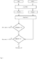
- a first embodiment of a method according to the invention is schematically shown in the flow chart of figure 1 .
- the heart rate (HR) of a person and the distal temperature (Td) at an ear of the person are measured and monitored.
- a first algorithm is used for estimation of slow varying trends in the distal temperature (Td) and the heart rate (HR).
- the algorithm (Algorithm 1) calculates global trends in the real-time measured distal temperature (Td) and heart rate (HR) time series by calculating progressing overall mean values of distal temperature (Tdm) and heart rate (HRm).
- the progressing overall mean value at a time instant is the mean calculated at said time instant starting from the first measured value of a time series. It is a recursively estimated mean of a time series by calculating each new time instant the average of all values from the start of the time series until the last measured data point.
- the slopes (dHRm/dt, dTdm/dt) of overall trends of mean values of the distal temperature (Tdm) and the heart rate (HRm) are schematically represented in figures 2 to 5 .
- a single driving experiment consisted of a four to five hours drive performed by the test subject and an accompanying co-driver. All test subjects followed comparable routes, consisting of a mix of different roads, i.e. highway, express roads and streets. During every drive two persons were present in the car, namely, the test subject as driver and the co-driver who checked continuously the proper functioning of the measuring equipment and monitored the status of the test driver.
- each driver made a short drive with the test car (approximately 15 minutes) to get himself acquainted to the car.
- the drowsiness level of the test subject i.e. the driver
- signals sampled at 1 Hz were used and the driver was assumed to be drowsy from a score of 6 on.
- a second embodiment of a method according to the invention uses the relation between the distal temperature (Td) and heart rate (HR) by calculating the difference between measured signals of distal temperature (Td) and heart rate (HR) in order to predict the onset of MSE or drowsiness.
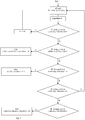
- the method is schematically represented in the flow charts of figures 6 and 7 and further illustrated in the graphical representations of figures 8 to 13 .
- a moving average for the distal temperature (Tdm1) as well as a progressing overall mean for the distal temperature (Tdm2) and the heart rate (HRm) are quantified by use of a first algorithm (Agorithm 3).
- Tdm1 signal reaches a maximum value (Tmax)
- Tmax a maximum value of Tdm1
- ⁇ Tdm(k) is smaller than Tr3, i.e. when the distal temperature Td is quite stable, and the slope of HRm(k)-Tdm2(k) as a function of time is negative, i.e. when the heat production relatively decreases, the operator is considered as being not drowsy.
- ⁇ Tdm(k) is smaller than Tr3 and the slope of HRm(k)-Tdm2(k) as a function of time is zero when HRm(k)-Tdm2(k) reaches a maximum value, i.e. after a period of increased heat production the heart rate decreases, the operator is considered as being drowsy.
- the moment of reaching the maximum HRm(k)-Tdm2(k) is the moment that the operator is considered to be drowsy.
- ⁇ Tdm(k) is larger than Tr3 and the slope of HRm(k)-Tdm2(k) as a function of time is negative, the operator is considered as being drowsy.
- the moment of crossing the Tr3 value is the moment that the operator is considered to be drowsy.
- ⁇ Tdm(k) is larger than Tr3, i.e. when there is vasoconstriction in the distal parts and heat loss is lowered, and the slope of HRm(k)-Tdm2(k) as a function of time is positive, i.e. when there is a relative increase in heat production and a decrease in heat loss, the operator is considered as being not drowsy.
- ⁇ Tdm(k) is larger than Tr3 and HRm(k)-Tdm2(k) as a function of time reaches a maximum, the operator is considered as being drowsy.
- the moment of reaching this maximum, after crossing Tr3, is the moment that the operator is considered to be drowsy.
- Test subject Driver code MSE predicted Time difference between predicted and actual onset of MSEs (min) Correct prediction D11 No - ⁇ D12 Yes 30 ⁇ D13 Yes -75 ⁇ D14 Yes -3 ⁇ D15 Yes 15 ⁇ D16 Yes -75 ⁇ D17 Yes 5 ⁇ D18 No - ⁇ D19 No - ⁇ D20 No - ⁇ D21 No - ⁇ D22 Yes 5 ⁇ D23 No - ⁇ D24 No - ⁇ D25 Yes 0 ⁇ D26 Yes -5 ⁇ D27 No - ⁇ D28 Yes -35 ⁇ D29 No - ⁇ D30 Yes -5 ⁇ D31 Yes 30 ⁇ D32 No - ⁇ D33 Yes -15 ⁇ D34 No - ⁇ D34 No - ⁇ D11 No - ⁇ D12 Yes 30 ⁇ D13 Yes -75 ⁇ D14 Yes -3 ⁇ D15 Yes 15 ⁇ D16 Yes -75 ⁇ D17 Yes 5 ⁇ D18 No - ⁇ D19
- experiments were designed using in total 63 subjects, including only male subjects, aged 22 to 28 years, right-handed and having a mean driving experience of over 16000 km/year.
- the main physiological variables were: eye movements, eye blink duration, blink frequency, head movements, EEG, galvanic skin response, heart rate, fingertip temperature and armpit temperature.
- test persons D11 to D34
- 11 test persons D35 to D45
- the driving tasks were basically divided into three parts: control, drowsiness induction and test. Table 3.
- the driving tasks started at 13h30. During the 2.5 hours long driving task the subject had no access to external stimuli such as a time watch, radio or conversation.
- the supervisor rated the subjects for six times during the induction part of the trial - each time the subjected started into a new repetition of the induction part.
- the subjects completed the same questionnaires on subjective rating of drowsiness and mood and concentration performance as in the morning and before the driving task, respectively (Altmuller, 2007).
- Table 2 results are shown for predicting the onset of the first MSEs on the training datasets.
- Table 3 shows the results for the validation datasets.
- a third possibility of a method differs from the first and second embodiment mainly in the manner that a change of the distal temperature is compared with a first threshold, before comparing a change of the heart rate with a second threshold or with the change of the distal temperature, as schematically presented in figure 14 (Algorithm 5).
- an alternative methodology for early detection of heavy drowsiness or MSE may be based on only distal temperature measurements (Algorithm 5). More specifically, using an integrated random walk model the overall trend of the distal temperature (Td) is estimated and this trend signal (Tdm) is subtracted from the original measured temperature signal (Td).
- the integrated random walk model is a time series model that is typically used for estimation of simple trends in time series and for smoothing operations.
- the resulting difference signal (Td-Tdm) describes mainly the higher frequent behaviour of the distal temperature (Td) and it can be modelled for instance by using a first order time-varying autoregressive analysis, resulting in a time series of AR(1) parameters.
- the first order time-varying autoregressive model is a model that regresses each value of a time series variable on its previous value.
- the coefficient or also the parameter describing the linear relationship between each value with its previous value (1st order) can be made function of time itself, resulting in a time-varying autoregressive parameter (AR(1)).
- the calculated AR(1) parameter values which are reflecting the dynamics of the thermoregulatory mechanisms, are compared with two threshold values (Tr4, Tr5) in order to determine a state of drowsiness or not.
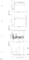
- a schematic overview including graphical representations of the working of the algorithm is shown in figure 14 .
- the different steps are: (1) calculation of slow trend of the original signal, (2) subtracting the trend signal from the original signal and (3) calculating the AR(1) parameters of the difference signal and comparing it with two threshold values (Tr4, Tr5).
- Test subject Driver code Drowsiness level ⁇ 7* according to scoring co-driver Drowsiness level ⁇ 7* according to algorithms of the method of the third embodiment Correct prediction D50 N N ⁇ D51 N N ⁇ D52 N N ⁇ D53 N N ⁇ D54 N N ⁇ D55 Y Y ⁇ D56 N N ⁇ D57 N N ⁇ D58 N N ⁇ D59 N N ⁇ D60 N N ⁇ D61 Y Y ⁇ D62 N N ⁇ D63 N N ⁇ D64 N N ⁇ D65 N N ⁇ D66 N N ⁇ D67 N N ⁇ * The drowsiness level of the driver was scored on a scale from 1, not drowsy at all, to 9, falling asleep; the driver was assumed to be drowsy from a score of 7 on.
- An example of a device for detection of drowsiness of a person based on a relationship between distal temperature and heart rate includes a temperature sensor for measuring a distal temperature in a predetermined distal region of the person as a measure for body heat loss, a heart rate sensor for measuring a heart rate of the person as a measure for body heat production, a computing unit for monitoring the measured distal temperature and the measured heart rate, and an output unit for generating a drowsiness signal and alerting the person when drowsiness in the immediate future is concluded.
- the computing unit compares a change of the distal temperature with a first threshold and, after detecting the passing of the first threshold, compares a change of the heart rate with a second threshold or with the change of the distal temperature.
- the output unit generates the drowsiness signal and alerts the person when the computing unit detects that the change of distal temperature passes the first threshold and, subsequently, detects that the change of the heart rate passes the second threshold and/or the change of the distal temperature is larger than the change of the heart rate.
- the computing unit preferably, monitors the change in the distal temperature and/or the heart rate, by monitoring the change of averaged values of the measured distal temperature and/or the measured heart rate.
- the averaged values are a moving average and/or a progressing overall mean.
- the computing unit preferably, calculates the progressing overall mean distal temperature from the measured distal temperature and calculates the progressing overall mean heart rate from the measured heart rate.
- the computing unit monitors the change of the progressing overall mean distal temperature and compares it with the first threshold. After the computing unit detects the passing of said first threshold, the computing unit monitors the change of the progressing overall mean heart rate and compares it with the second threshold.
- the output unit generates the drowsiness signal when the computing unit detects that the change of progressing overall mean distal temperature passes the first threshold and, subsequently, the change of the progressing overall mean heart rate passes the second threshold.
- the computing unit preferably, detects a maximum in the distal temperature, and monitors the change in the distal temperature after reaching the maximum in the distal temperature, to compare the change with the first threshold corresponding to a maximal change in the distal temperature, and detects when the distal temperature passes the first threshold.
- the computing unit also monitors a change in the difference between the heart rate and the distal temperature, after detecting the distal temperature passing the first threshold, to compare the change with the second threshold, and detects when the change passes the second threshold.
- the output unit generates the drowsiness signal to alert the person of the conclusion that drowsiness is impending when the computing unit detects that the distal temperature passes the maximal change in the distal temperature and subsequently detects that the change of the distal temperature is larger than the change of the heart rate or subsequently the change in the distal temperature equals the change in the heart rate.
- the output unit preferably, generates the drowsiness signal and alerts the person when the computing unit detects that the change in the distal temperature equals the change in the heart rate.
- the invention is not restricted to the method and device according to the invention as described above.
- other distal regions such as fingers or toes, may be used for measuring the distal temperature.
- the immediate future may also refer to a period of less than 10 minutes.
- the warning signal may also include an activating signal, which prevents and/or delays drowsiness.
Landscapes
- Health & Medical Sciences (AREA)
- Life Sciences & Earth Sciences (AREA)
- Engineering & Computer Science (AREA)
- Biomedical Technology (AREA)
- Medical Informatics (AREA)
- Public Health (AREA)
- General Health & Medical Sciences (AREA)
- Physics & Mathematics (AREA)
- Pathology (AREA)
- Physiology (AREA)
- Surgery (AREA)
- Animal Behavior & Ethology (AREA)
- Biophysics (AREA)
- Molecular Biology (AREA)
- Veterinary Medicine (AREA)
- Heart & Thoracic Surgery (AREA)
- Cardiology (AREA)
- Psychiatry (AREA)
- Epidemiology (AREA)
- Business, Economics & Management (AREA)
- Primary Health Care (AREA)
- Psychology (AREA)
- Social Psychology (AREA)
- Signal Processing (AREA)
- Pulmonology (AREA)
- Hospice & Palliative Care (AREA)
- Educational Technology (AREA)
- Artificial Intelligence (AREA)
- Computer Vision & Pattern Recognition (AREA)
- Child & Adolescent Psychology (AREA)
- Developmental Disabilities (AREA)
- Databases & Information Systems (AREA)
- Data Mining & Analysis (AREA)
- Emergency Management (AREA)
- General Physics & Mathematics (AREA)
- General Business, Economics & Management (AREA)
- Measurement Of The Respiration, Hearing Ability, Form, And Blood Characteristics Of Living Organisms (AREA)
- Measuring Pulse, Heart Rate, Blood Pressure Or Blood Flow (AREA)
- Traffic Control Systems (AREA)
Description
- The present invention concerns a method and device for detection of drowsiness of a person, such as a machine operator, pilot, driver or conductor, wherein a distal temperature in a predetermined distal region of the person and a heart rate of the person are measured and monitored. According to the present invention drowsiness includes micro sleep events (MSE) and falling asleep.
- Drowsiness and falling asleep of operators are identified as reasons for many fatalities. For example, in the early 1990s researchers using epidemiologic data began investigating sleepiness and sleep deprivation as causes of accidents. Falling asleep while driving associated with sleep restriction and nocturnal driving has been incriminated in 20% of traffic accidents (Philip and Sagaspe, 2011). Therefore, it is important that drowsiness while operating means of transport or other processes can be detected in an early stage in order to prevent accidents.
- It is known that sleep regulatory and thermoregulatory systems in homeotherms are closely interrelated (Krauchi, 2007). Both are driven, independently, by two interacting physiological principles, homeostasis and circadian regulation.
- The human body consists of two thermophysiological compartments, the heat producing, homeothermic core, and the heat loss regulating, poikilothermic shell (Mount, 1979). All peripheral tissues such as fat, skin, and in particular skeletal muscles of the legs and the arms can contribute substantially to the size of the shell, provided that peripheral flow is low. Therefore, rates of blood flow through muscles and skin are the main determinants of the shell size variability and hence of peripheral insulation. The distal skin regions, in particular fingers and toes, are the main thermoeffectors of the body to lose body heat. Therefore, the distal skin temperatures provide a good measure of the shell size (Krauchi and de Boer, 2010).
- Thermoregulatory distal skin blood flow is regulated by the autonomic nervous system via constriction or dilatation of arteriovenous anastomoses (AVA's). These are shunts between arterioles and venules, exclusively found in distal skin regions, e.g. fingers and toes. When they are open warm blood flows rapidly and directly from arterioles to the dermal venous plexus enabling an efficient heat exchange from the core to the distal skin. The distal to proximal skin temperature gradient (DPG), i.e. the difference between the distal and proximal skin temperature, provides a selective measure of distal skin blood flow, and hence body heat loss via the extremities. Heart rate (HR) can be seen as an indirect measure of intrasubject variation of heat production. So, measuring distal and proximal skin temperature and heart rate allows estimating indirectly (changes in) heat loss and heat production.
- Typically, when falling asleep, heat production is first lowered by a decrease in the heart rate, followed by an increase in distal temperatures and an increase in heat loss, resulting in a decrease in core body temperature (CBT). Before falling asleep, people can experience feelings of light to heavy drowsiness and even micro sleep events (MSE), which are brief unintended episodes with loss of attention and which can be potentially dangerous, especially when operating processes such as driving a vehicle or a train, flying an airplane, navigating a ship, air traffic control, etc..
- Current systems for detection of drowsiness are based on e.g. changes of heart rate, temperature changes of breath, skin or eyes, movement of head and eyelids or movement of the steering wheel. However, the accuracy of the present systems is rather low such that operators ignore warning signals which often occur much too early. A warning signal indicating that drowsiness will occur within 30 to 60 minutes or more, will in most circumstances be ignored and hence will be ineffective.
- Patents
GB-2375645-A GB-2491984-A - The invention aims to remedy the above mentioned disadvantages of existing detection systems. Therefore, for developing monitor systems for drowsiness detection, distal temperatures and heart rate should be monitored in real-time and the relationship between distal temperatures and heart rate is a key feature in the determination and prediction of the level of drowsiness.
- The aim of the present invention is to provide a method and device allowing reliable, accurate and real-time detection of drowsiness in operators. Hence, the invention aims to offer a method and device to predict if future drowsiness or MSEs will occur and to predict when drowsiness or MSEs will occur.
- The above mentioned objects are realised by the method and device having the specific features set out in the appended claims. Specific features for preferred embodiments of the invention are set out in the dependent claims.
- Practically, the method and device, according to the invention, is based on a relationship between the distal temperature and the heart rate, wherein the distal temperature is a measure for body heat loss and the heart rate is a measure for body heat production. A change of the distal temperature is compared with a first threshold and, after passing this first threshold, a change of the heart rate is compared with a second threshold or with the change of the distal temperature, wherein drowsiness in the immediate future is concluded when the change of distal temperature passes the first threshold and, subsequently, the change of the heart rate passes the second threshold or, subsequently, the change of the distal temperature is larger than the change of the heart rate.
- According to the invention the immediate future refers to a period of less than 60 minutes, preferably less than 30 minutes, in which drowsiness will occur. Advantageously, the immediate future corresponds to a period of approximately 10 to 15 minutes.
- Other particularities and advantages of the invention will become clear from the following description and accompanying drawings of practical embodiments of the method and device of the invention; the description and drawings are given as an example only and do not limit the scope of the claimed protection in any way.
-
Figure 1 is a flow chart of the method according to a first embodiment of the invention. -
Figure 2 is a graph, which schematically represents the slopes (dHRm/dt and dTdm/dt) of the overall trends of the mean values of the distal temperature (Tdm) and the heart rate (HRm) according to the first embodiment of the invention, wherein dTdm/dt does not cross a first threshold (Tr1) and dHR/dt does not cross a second threshold (Tr2) and thus the subject person is evaluated as not drowsy. -
Figure 3 is a graph as infigure 2 , wherein dTdm/dt does not cross Tr1 and dHR/dt does cross Tr2 and thus the subject person is evaluated as not drowsy. -
Figure 4 is a graph as infigure 2 , wherein dTdm/dt does cross Tr1 and dHR/dt does not cross Tr2 and thus the subject person is evaluated as not drowsy. -
Figure 5 is a graph as infigure 2 , wherein dTdm/dt does cross Tr1 and subsequently dHR/dt does cross Tr2 and thus the subject person is evaluated as drowsy. -
Figures 6 and7 are a flow chart of the method according to a second embodiment of the invention. -
Figure 8 is a graphical representation of the working of the method offigures 6 and7 . -
Figure 9 is a graphical representation of a first scenario according to the second embodiment of the invention, in which the difference between the maximal distal temperature (Tmax) and the actual mean distal temperature (Tdm1(k)) (ΔTdm(k)=Tmax-Tdm1(k)) is smaller than the first threshold (Tr1) and the slope of HRm1(k)-Tdm2(k) as a function of time is negative and wherein the subject person is evaluated as not drowsy. -
Figure 10 is a graphical representation of the second embodiment of the invention, in which ΔTdm(k) is smaller than Tr1 and HRm1(k)-Tdm2(k) as a function of time reaches a maximum value and wherein the subject person is evaluated as drowsy. -
Figure 11 is a graphical representation of a third scenario, in which ΔTdm(k) is larger than Tr1 and the slope of HRm1(k)-Tdm2(k) as a function of time is negative and wherein the subject person is evaluated as drowsy. -
Figure 12 is a graphical representation of a fourth scenario, in which ΔTdm(k) is larger than Tr1 and the slope of HRm1(k)-Tdm2(k) as a function of time is positive and wherein the subject person is evaluated as not drowsy. -
Figure 13 is a graphical representation of a fifth scenario, in which ΔTdm(k) is larger than Tr1 and HRm1(k)-Tdm2(k) as a function of time reaches a maximum and wherein the subject person is evaluated as drowsy. -
Figure 14 is a flow chart of the method according to a third embodiment of the invention, including charts of (A) distal temperature (Td), (B) mean values of the distal temperature (Tdm), (C) difference between distal temperature (Td) and mean values of the distal temperature (Tdm), and (D) time-varying parameter of a first order autoregressive model (AR(1)) of the difference between distal temperature (Td) and mean values of the distal temperature (Tdm). - The invention generally concerns a method and device for detection of drowsiness of a person wherein drowsiness of the person is determined after evaluating a change in the balance between body heat loss and body heat production. The method is based on a relationship between distal temperature and heart rate, which reflects the balance between body heat loss and body heat production. According to the method of the invention, a distal temperature (Td) in a predetermined distal region of the person is measured and monitored as a measure for body heat loss, and a heart rate (HR) of the person is measured and monitored as a measure for body heat production.
- The method is based on dynamics of measured thermoregulatory signals, e.g. comparing changes of distal temperature and heart rate as a function of time. This has the advantage that it allows detecting thermoregulatory changes that precedes drowsiness, e.g. up to 45 minutes for some subjects, before the steady state values of body temperature and/or heart rate start dropping.
- In order to predict and monitor the drowsiness in practice, an apparatus is needed consisting of a sensing unit, a computing unit, a warning unit and/or an output unit. The sensing unit includes a temperature sensor and a heart rate sensor. It measures the heart rate (HR) and the distal temperature (Td). Both measured bio-signals are processed in real-time in the computing unit. The computing unit communicates with a warning and/or output unit, which generates warnings for the operator. The apparatus can be made mobile where the operator wears the sensors and the computing power (e.g. smart phone) on the body, or the measuring hardware and computing power can be integrated in the operator's environment (e.g. via the roof of a car, the seat, the seat belt or the head support).
- A first embodiment of a method according to the invention is schematically shown in the flow chart of
figure 1 . - The heart rate (HR) of a person and the distal temperature (Td) at an ear of the person are measured and monitored.
- A first algorithm (Algorithm 1) is used for estimation of slow varying trends in the distal temperature (Td) and the heart rate (HR). The algorithm (Algorithm 1) calculates global trends in the real-time measured distal temperature (Td) and heart rate (HR) time series by calculating progressing overall mean values of distal temperature (Tdm) and heart rate (HRm). The progressing overall mean value at a time instant is the mean calculated at said time instant starting from the first measured value of a time series. It is a recursively estimated mean of a time series by calculating each new time instant the average of all values from the start of the time series until the last measured data point.
- In order to estimate the relative balance between heat production, which is related to the heart rate (HR) and heat losses, which is related to the distal temperature (Td), changes in the distal temperature (dTd/dt) and changes in the heart rate (dHR/dt) are monitored using a second algorithm (Algorithm 2) for the estimation of slopes in slow varying trends of the distal temperature (Td) and the heart rate (HR). By using a dynamic linear regression approach, the second algorithm (Algorithm 2) quantifies at each time instance the slopes of slow trends of progressing overall mean values of the distal temperature (Tdm) and the heart rate (HRm) calculated by means of the first algorithm (Algorithm 1).
- The slopes (dHRm/dt, dTdm/dt) of overall trends of mean values of the distal temperature (Tdm) and the heart rate (HRm) are schematically represented in
figures 2 to 5 . - When the slope of the trend of the mean value of the distal temperature (dTdm/dt) crosses a predefined first threshold (Tr1), the slope of the trend of the mean value of the heart rate (dHRm/dt) is monitored. When the latter, subsequently, crosses a second threshold (Tr2), the operator is defined to be drowsy, as schematically represented in the graph of
figure 5 . The moment of crossing the second threshold (Tr2) is defined as the moment of onset of drowsiness. - In all other cases, schematically represented in
figures 2 to 4 , the operator is assumed to be not drowsy. Hence, for the scenario when dTdm/dt crosses Tr1, but dHR/dt does not cross Tr2 or when dTdm/dt does not cross Tr1, the operator is assumed not to be drowsy. - In order to test the methodology according to the first embodiment of the invention, an experiment was performed, in which a total of 10 persons (D1 to D10) have been used as test subjects for driving a fully equipped test car. In total 16 datasets were generated. The results are shown in table 1. Depending on the test subject, the drives started in the morning at 10h00, in the afternoon at 15h00, in the evening at 20h00 or at night at 24h00.
- For the experiment a test car was used, equipped with the following sensors/sensing systems:
- 1. faceLAB eye tracking system (60 fps) for measuring of eye movements, head position and rotation, eyelid aperture and pupil size;
- 2. webcam for registration of driving behaviour (30 fps);
- 3. car variables measured via the can bus of the test car: longitudinal velocity (m/s); longitudinal acceleration (m/s2); lateral velocity (m/s); lateral acceleration (m/s2); throttle pedal position (%); brake pedal force (N); steering torque (ft-lbs); steering wheel angle (deg); steering wheel angle rate (deg/s).
- 4. physiological variables: heart rate (HR): sampling rate: 256 Hz, derived from ECG measured wirelessly via chest belt (resolution: 1 bpm); respiration rate: sampling rate: 32 Hz, measured via deformation of chest belt (resolution: 0.01%; range: 0 - 75%); activity: sampling rate: 128 Hz, measured via accelerometer (resolution: 3 mg; range: +/- 6 g); skin temperature: sampling rate: 32 Hz (resolution: 0.1 °C); ear temperature (Td): idem as skin temperature; body temperature (armpit): idem as skin temperature.
- A single driving experiment consisted of a four to five hours drive performed by the test subject and an accompanying co-driver. All test subjects followed comparable routes, consisting of a mix of different roads, i.e. highway, express roads and streets. During every drive two persons were present in the car, namely, the test subject as driver and the co-driver who checked continuously the proper functioning of the measuring equipment and monitored the status of the test driver.
- Before following the programmed route, each driver made a short drive with the test car (approximately 15 minutes) to get himself acquainted to the car.
- The drowsiness level of the test subject, i.e. the driver, was scored by the driver as well as by the co-driver on a scale from 1, corresponding to not drowsy at all, to 9, corresponding to falling asleep. In the results shown in table 1, signals sampled at 1 Hz were used and the driver was assumed to be drowsy from a score of 6 on.
- A second embodiment of a method according to the invention uses the relation between the distal temperature (Td) and heart rate (HR) by calculating the difference between measured signals of distal temperature (Td) and heart rate (HR) in order to predict the onset of MSE or drowsiness.
- The method is schematically represented in the flow charts of
figures 6 and7 and further illustrated in the graphical representations offigures 8 to 13 . - First, a moving average for the distal temperature (Tdm1) as well as a progressing overall mean for the distal temperature (Tdm2) and the heart rate (HRm) are quantified by use of a first algorithm (Agorithm 3). Next, when the Tdm1 signal reaches a maximum value (Tmax), all next values of Tdm1 are compared with this maximum value (ΔTdm(k)=Tmax-Tdm1(k)).
- In parallel, the calculated trends for distal temperature (Tdm2) and heart rate (HRm) are fed into a second algorithm (Algorithm 4) to calculate the slope of HRm-Tdm2.
- Next, the calculated value of ΔTdm(k) is compared with a threshold value Tr3 and the slope of HRm-Tdm2 is quantified by use of a second algorithm (Algorithm 4).
- Several scenarios can occur that can be linked to the drowsiness state of the operator.
- In a first scenario, as schematically represented in
figure 9 , ΔTdm(k) is smaller than Tr3, i.e. when the distal temperature Td is quite stable, and the slope of HRm(k)-Tdm2(k) as a function of time is negative, i.e. when the heat production relatively decreases, the operator is considered as being not drowsy. - In a second scenario, as schematically represented in
figure 10 , ΔTdm(k) is smaller than Tr3 and the slope of HRm(k)-Tdm2(k) as a function of time is zero when HRm(k)-Tdm2(k) reaches a maximum value, i.e. after a period of increased heat production the heart rate decreases, the operator is considered as being drowsy. The moment of reaching the maximum HRm(k)-Tdm2(k) is the moment that the operator is considered to be drowsy. - In a third scenario, as schematically represented in
figure 11 , ΔTdm(k) is larger than Tr3 and the slope of HRm(k)-Tdm2(k) as a function of time is negative, the operator is considered as being drowsy. The moment of crossing the Tr3 value is the moment that the operator is considered to be drowsy. - In a fourth scenario, as schematically represented in
figure 12 , ΔTdm(k) is larger than Tr3, i.e. when there is vasoconstriction in the distal parts and heat loss is lowered, and the slope of HRm(k)-Tdm2(k) as a function of time is positive, i.e. when there is a relative increase in heat production and a decrease in heat loss, the operator is considered as being not drowsy. - In a fifth scenario, as schematically represented in
figure 13 , ΔTdm(k) is larger than Tr3 and HRm(k)-Tdm2(k) as a function of time reaches a maximum, the operator is considered as being drowsy. The moment of reaching this maximum, after crossing Tr3, is the moment that the operator is considered to be drowsy. - The method according to the second embodiment of the invention was tested on experimental data generated by a driving simulator under controlled conditions. The results are shown in tables 2 and 3.
Table 2. Prediction performance of the second embodiment of the method according to the invention on training datasets; 21 out of 24 datasets have been correctly classified. Test subject Driver code MSE predicted Time difference between predicted and actual onset of MSEs (min) Correct prediction D11 No - ✔ D12 Yes 30 ✔ D13 Yes -75 ✔ D14 Yes -3 ✔ D15 Yes 15 ✔ D16 Yes -75 × D17 Yes 5 ✔ D18 No - ✔ D19 No - ✔ D20 No - ✔ D21 No - ✔ D22 Yes 5 ✔ D23 No - ✔ D24 No - ✔ D25 Yes 0 ✔ D26 Yes -5 ✔ D27 No - ✔ D28 Yes -35 × D29 No - ✔ D30 Yes -5 ✔ D31 Yes 30 ✔ D32 No - × D33 Yes -15 ✔ D34 No - ✔ - More specifically, experiments were designed using in total 63 subjects, including only male subjects, aged 22 to 28 years, right-handed and having a mean driving experience of over 16000 km/year. During the simulator experiments several variables were measured on the car (distance along roadway centreline, total vehicle longitudinal velocity, total vehicle lateral velocity, steering wheel angle, etc.) as well as on the driver. The main physiological variables were: eye movements, eye blink duration, blink frequency, head movements, EEG, galvanic skin response, heart rate, fingertip temperature and armpit temperature. For this analysis 24 test persons (D11 to D34) were used for training the algorithms and 11 test persons (D35 to D45) for validation purposes. The driving tasks were basically divided into three parts: control, drowsiness induction and test.
Table 3. Prediction performance of the second embodiment of the method according to the invention on validation datasets; 8 out of 11 datasets have been correctly classified. Test subject Driver code MSE predicted Time difference between predicted and actual onset of MSEs (min) Correct prediction D35 No - ✔ D36 No - ✔ D37 No - ✔ D38 No - ✔ D39 Yes 12 ✔ D40 Yes -45 × D41 Yes 0 ✔ D42 Yes 5 ✔ D43 No -10 × D44 Yes 5 ✔ D45 Yes - × - During the control part of about 9 km, the subjects drove through tight curves with heavy oncoming traffic, changing visibility (fog banks) and the request to drive as fast as possible. The following drowsiness induction part showed reduced visibility due to fog and a speed limit of 50 km/h throughout the whole length of about 110 km (six identical laps of about 18 km). The test part at the end of the scenario repeated exactly the control part from the beginning.
- The driving tasks started at 13h30. During the 2.5 hours long driving task the subject had no access to external stimuli such as a time watch, radio or conversation. In order to get a drowsiness estimation for each subject straight after the trial, the supervisor rated the subjects for six times during the induction part of the trial - each time the subjected started into a new repetition of the induction part. After the trial, the subjects completed the same questionnaires on subjective rating of drowsiness and mood and concentration performance as in the morning and before the driving task, respectively (Altmuller, 2007).
- In table 2, results are shown for predicting the onset of the first MSEs on the training datasets. Table 3 shows the results for the validation datasets.
- A third possibility of a method differs from the first and second embodiment mainly in the manner that a change of the distal temperature is compared with a first threshold, before comparing a change of the heart rate with a second threshold or with the change of the distal temperature, as schematically presented in
figure 14 (Algorithm 5). - In this implementation an alternative methodology for early detection of heavy drowsiness or MSE may be based on only distal temperature measurements (Algorithm 5). More specifically, using an integrated random walk model the overall trend of the distal temperature (Td) is estimated and this trend signal (Tdm) is subtracted from the original measured temperature signal (Td). The integrated random walk model is a time series model that is typically used for estimation of simple trends in time series and for smoothing operations. The resulting difference signal (Td-Tdm) describes mainly the higher frequent behaviour of the distal temperature (Td) and it can be modelled for instance by using a first order time-varying autoregressive analysis, resulting in a time series of AR(1) parameters. The first order time-varying autoregressive model is a model that regresses each value of a time series variable on its previous value. The coefficient or also the parameter describing the linear relationship between each value with its previous value (1st order) can be made function of time itself, resulting in a time-varying autoregressive parameter (AR(1)). The calculated AR(1) parameter values, which are reflecting the dynamics of the thermoregulatory mechanisms, are compared with two threshold values (Tr4, Tr5) in order to determine a state of drowsiness or not.
- A schematic overview including graphical representations of the working of the algorithm (Algorithm 5) is shown in
figure 14 . The different steps are: (1) calculation of slow trend of the original signal, (2) subtracting the trend signal from the original signal and (3) calculating the AR(1) parameters of the difference signal and comparing it with two threshold values (Tr4, Tr5). - When the calculated AR(1) parameter value exceeds a first threshold value (Tr4, Tr5), drowsiness in the near future is expected. For further evaluation of the onset of drowsiness, a change of the heart rate is compared with a second threshold or with the change of the distal temperature, as described for the above first and second embodiments.
Table 4. Prediction performance of the third alternative of the method on validation datasets using ear temperature (Td) as measured bio-responses; 18 out of 18 datasets have been correctly classified. Test subject Driver code Drowsiness level ≥ 7* according to scoring co-driver Drowsiness level ≥ 7* according to algorithms of the method of the third embodiment Correct prediction D50 N N ✔ D51 N N ✔ D52 N N ✔ D53 N N ✔ D54 N N ✔ D55 Y Y ✔ D56 N N ✔ D57 N N ✔ D58 N N ✔ D59 N N ✔ D60 N N ✔ D61 Y Y ✔ D62 N N ✔ D63 N N ✔ D64 N N ✔ D65 N N ✔ D66 N N ✔ D67 N N ✔ * The drowsiness level of the driver was scored on a scale from 1, not drowsy at all, to 9, falling asleep; the driver was assumed to be drowsy from a score of 7 on. - An example of a device for detection of drowsiness of a person based on a relationship between distal temperature and heart rate according to the invention includes a temperature sensor for measuring a distal temperature in a predetermined distal region of the person as a measure for body heat loss, a heart rate sensor for measuring a heart rate of the person as a measure for body heat production, a computing unit for monitoring the measured distal temperature and the measured heart rate, and an output unit for generating a drowsiness signal and alerting the person when drowsiness in the immediate future is concluded.
- According to the invention, the computing unit compares a change of the distal temperature with a first threshold and, after detecting the passing of the first threshold, compares a change of the heart rate with a second threshold or with the change of the distal temperature. The output unit generates the drowsiness signal and alerts the person when the computing unit detects that the change of distal temperature passes the first threshold and, subsequently, detects that the change of the heart rate passes the second threshold and/or the change of the distal temperature is larger than the change of the heart rate.
- The computing unit, preferably, monitors the change in the distal temperature and/or the heart rate, by monitoring the change of averaged values of the measured distal temperature and/or the measured heart rate. The averaged values are a moving average and/or a progressing overall mean.
- The computing unit, preferably, calculates the progressing overall mean distal temperature from the measured distal temperature and calculates the progressing overall mean heart rate from the measured heart rate. The computing unit monitors the change of the progressing overall mean distal temperature and compares it with the first threshold. After the computing unit detects the passing of said first threshold, the computing unit monitors the change of the progressing overall mean heart rate and compares it with the second threshold. The output unit generates the drowsiness signal when the computing unit detects that the change of progressing overall mean distal temperature passes the first threshold and, subsequently, the change of the progressing overall mean heart rate passes the second threshold.
- The computing unit, preferably, detects a maximum in the distal temperature, and monitors the change in the distal temperature after reaching the maximum in the distal temperature, to compare the change with the first threshold corresponding to a maximal change in the distal temperature, and detects when the distal temperature passes the first threshold. The computing unit also monitors a change in the difference between the heart rate and the distal temperature, after detecting the distal temperature passing the first threshold, to compare the change with the second threshold, and detects when the change passes the second threshold. The output unit generates the drowsiness signal to alert the person of the conclusion that drowsiness is impending when the computing unit detects that the distal temperature passes the maximal change in the distal temperature and subsequently detects that the change of the distal temperature is larger than the change of the heart rate or subsequently the change in the distal temperature equals the change in the heart rate.
- The output unit, preferably, generates the drowsiness signal and alerts the person when the computing unit detects that the change in the distal temperature equals the change in the heart rate.
- Naturally, the invention is not restricted to the method and device according to the invention as described above. Thus, besides the distal ear temperature, other distal regions, such as fingers or toes, may be used for measuring the distal temperature. Furthermore, according to the invention the immediate future may also refer to a period of less than 10 minutes. The warning signal may also include an activating signal, which prevents and/or delays drowsiness.
-
- Altmüller T. 2007. Driver monitoring and drowsiness detection by steering signal analysis. PhD thesis, Universität der Bundeswehr München, Germany.
- Krauchi K. 2007. The human sleep-wake cycle reconsidered from a thermoregulatory point of view. Physiology & Behavior 90(2-3): 236-245.
- Krauchi K. and de Boer 2010. The interrelationship between sleep regulation and thermoregulation. Frontiers in Bioscience 15: 604-625.
- Mount L.E. 1979. Adaptation to thermal environment. Man and his productive animals. Edward Arnold, London.
- Philip P. and Sagaspe P. 2011. Sleep and accidents. Bulletin de l'Academie nationale de Medicine 195(7): 1635-1643.
| Test subject Driver code | Drowsiness level ≥ 6* according to scoring co-driver | Drowsiness level ≥ 6* according to the method of the first embodiment | Correct prediction | Time difference between predicted and actual onset of drowsiness (min) |
| D1 | No | No | ✔ | - |
| D2 | Yes | Yes | ✔ | -5 |
| D3 | No | No | ✔ | - |
| D4-1 | No | Yes | ✔ | - |
| D4-2 | No | Yes | ✔ | - |
| D4-3 | Yes | Yes | ✔ | 0 |
| D5-1 | No | No | ✔ | - |
| D5-2 | Yes | Yes | ✔ | +10 |
| D6-1 | No | No | ✔ | - |
| D6-2 | No | No | ✔ | - |
| D7 | Yes | No | × | - |
| D8-1 | No | No | ✔ | - |
| D8-2 | Yes | Yes | ✔ | -15 |
| D9-1 | Yes | Yes | ✔ | +25 |
| D9-2 | Yes | No | × | - |
| D10 | No | Yes | × | - |
| * The drowsiness level of the driver was scored on a scale from 1, not drowsy at all, to 9, falling asleep; the driver was assumed to be drowsy from a score of 6 on. |
Claims (12)
- Method for detection of drowsiness of a person, based on a relationship between distal temperature (Td) and heart rate (HR), wherein- a distal temperature (Td) in a predetermined distal region of the person is measured and monitored as a measure for body heat loss, and- a heart rate (HR) of the person is measured and monitored as a measure for body heat production, characterized in that a change in balance between body heat loss and body heat production is evaluated by comparing a change of the distal temperature (dTdm/dt, ΔTdm) with a first threshold (Tr1, TR3) and, after passing said first threshold (Tr1, Tr3), comparing a change of the heart rate (dHR/dt) with a second threshold (Tr2) or with the change of the distal temperature (dTdm/dt),wherein drowsiness in the immediate future is concluded when the change of distal temperature (dTdm/dt, ΔTdm) passes said first threshold (Tr1, Tr3) and, subsequently, the change of the heart rate (dHR/dt) passes said second threshold (Tr2) or, subsequently, the change of the distal temperature (dTdm/dt) is larger than the change of the heart rate (dHRm/dt).
- Method according to claim 1, wherein the change of the distal temperature is monitored by monitoring the change of averaged values of the measured distal temperature (dTdm/dt, ΔTdm) and/or wherein the change of the heart rate is monitored by monitoring the change of averaged values of the measured heart rate (dHRm/dt), wherein the averaged values are a moving average and/or a progressing overall mean.
- Method according to claim 2, wherein a progressing overall mean distal temperature (Tdm) is calculated from the measured distal temperature (Td) and a progressing overall mean heart rate (HRm) is calculated from the measured heart rate (HR),
wherein further a change of the progressing overall mean distal temperature (dTdm/dt) is monitored and compared with the first threshold (Tr1),
wherein, after passing said first threshold (Tr1), a change of the progressing overall mean heart rate (dHRm/dt) is monitored and compare with a second threshold (Tr2),
wherein drowsiness in the immediate future is concluded when the change of progressing overall mean distal temperature (dTdm/dt) passes said first threshold (Tr1) and, subsequently, the change of the progressing overall mean heart rate (dHRm/dt) passes said second threshold (Tr2). - Method according to claims 1 or 2, wherein a maximum in the distal temperature (Tmax) is determined, and, after reaching said maximum in the distal temperature (Tmax), the change in the distal temperature (ΔTdm) is monitored and compared with the first threshold (Tr3) corresponding to a maximal change in the distal temperature,
wherein, after passing said first threshold (Tr3), the change in the heart rate (dHRm/dt) and the change in the distal temperature (dTdm/dt) are monitored and compared with each other,
wherein further drowsiness in the immediate future is concluded when the distal temperature (Tdm) passes said first threshold (Tr3) and, subsequently, the change of the distal temperature (dTdm/dt) is larger than the change of the heart rate (dHRm/dt). - Method according to claim 4, wherein drowsiness in the immediate future is concluded when the change of the distal temperature (dTdm/dt) is equal to the change of the heart rate (dHRm/dt).
- Method according to any of the claims 1 to 6, wherein the immediate future corresponds to a period of less than 60 minutes, preferably less than 30 minutes, more preferably between 10 minutes and 15 minutes.
- Device for detection of drowsiness of a person, based on a relationship between distal temperature (Td) and heart rate (HR), wherein it comprises- a temperature sensor for measuring a distal temperature (Td) in a predetermined distal region of the person as a measure for body heat loss, and- a heart rate sensor for measuring a heart rate (HR) of the person as a measure for body heat production,- a computing unit for monitoring the measured distal temperature (Td) and the measured heart rate (HR), and- an output unit for generating a drowsiness signal when drowsiness in the immediate future is concluded,characterised in that the computing unit is adapted- to compare a change of the distal temperature (dTdm/dt, ΔTdm) with a first threshold (Tr1, Tr3) and, after detecting the passing of said first threshold (Tr1, Tr3),- to compare a change of the heart rate (dHRm/dt) with a second threshold (Tr2) or with the change of the distal temperature (dTdm/dt),wherein the output unit is adapted to generate the drowsiness signal when the computing unit- detects that the change of distal temperature (dTdm/dt, ΔTdm) passes said first threshold (Tr1, Tr3) and, subsequently,- detects that the change of the heart rate (dHRm/dt) passes said second threshold (Tr2) and/or the change of the distal temperature (dTdm/dt) is larger than the change of the heart rate (dHRm/dt).
- Device according to claim 7, wherein the computing unit is adapted to monitor the change in the distal temperature (dTd/dt) and/or the heart rate (dHR/dt), by monitoring the change of averaged values of the measured distal temperature (dTdm/dt) and/or the measured heart rate (dHRm/dt), wherein the averaged values are a moving average and/or a progressing overall mean.
- Device according to claim 8, wherein the computing unit is adapted to calculate the progressing overall mean distal temperature (Tdm) from the measured distal temperature (Td) and to calculate the progressing overall mean heart rate (HRm) from the measured heart rate (HR),
wherein the computing unit is adapted to monitor the change of the progressing overall mean distal temperature (dTdm/dt) and to compare it with the first threshold (Tr1), and further, after the computing unit detects the passing of said first threshold (Tr1), to monitor the change of the progressing overall mean heart rate (dHRm/dt) and to compare it with the second threshold (Tr2),
wherein the output unit is adapted to generate the drowsiness signal when the computing unit detects that the change of progressing overall mean distal temperature (dTdm/dt) passes said first threshold (Tr1) and, subsequently, the change of the progressing overall mean heart rate (dHRm/dt) passes said second threshold (Tr2). - Device according to claims 7 or 8, wherein the computing unit is adapted to detect a maximum in the distal temperature (Tmax), and to monitor the change in the distal temperature (ΔTdm) after reaching said maximum in the distal temperature (Tmax), to compare said change with the first threshold (Tr3) corresponding to a maximal change in the distal temperature, and to detect when the distal temperature (Tdm) passes said first threshold (Tr3), wherein the computing unit is further adapted to monitor a change in the difference between the heart rate (HRm) and the distal temperature (Tdm), after detecting the distal temperature (Tdm) passing said first threshold (Tr3), wherein the output unit is adapted to generate the drowsiness signal when the computing unit detects that the distal temperature (Tdm) passes said maximal change in the distal temperature and subsequently detects that the change of the distal temperature (dTdm/dt) is larger than the change of the heart rate (dHRm/dt) or subsequently the change in the distal temperature (dTdm/dt) equals the change in the heart rate (dHRm/dt).
- Device according to any of the claims 7 to 10, wherein the output unit is adapted to generate the drowsiness signal when the computing unit detects that the change in the distal temperature (dTdm/dt) equals the change in the heart rate (dHRm/dt).
- Device according to any of the claims 7 to 11, wherein the immediate future corresponds to a period of less than 60 minutes, preferably less than 30 minutes, more preferably between 10 minutes and 15 minutes.
Applications Claiming Priority (1)
| Application Number | Priority Date | Filing Date | Title |
|---|---|---|---|
| GBGB1313986.0A GB201313986D0 (en) | 2013-08-05 | 2013-08-05 | Method and device for accurate realtime detection of drowsiness in operators using physiological responses |
Publications (2)
| Publication Number | Publication Date |
|---|---|
| EP2842490A1 EP2842490A1 (en) | 2015-03-04 |
| EP2842490B1 true EP2842490B1 (en) | 2016-06-01 |
Family
ID=49224172
Family Applications (1)
| Application Number | Title | Priority Date | Filing Date |
|---|---|---|---|
| EP14179949.4A Active EP2842490B1 (en) | 2013-08-05 | 2014-08-05 | Method and device for accurate real-time detection of drowsiness in operators using physiological responses |
Country Status (4)
| Country | Link |
|---|---|
| US (1) | US11311221B2 (en) |
| EP (1) | EP2842490B1 (en) |
| ES (1) | ES2587935T3 (en) |
| GB (1) | GB201313986D0 (en) |
Families Citing this family (12)
| Publication number | Priority date | Publication date | Assignee | Title |
|---|---|---|---|---|
| US9990552B2 (en) * | 2014-09-21 | 2018-06-05 | Progress Rail Locomotive Inc. | Operator fatigue monitoring system |
| ES2964968T3 (en) | 2016-06-17 | 2024-04-10 | Predictive Safety Srp Inc | Memory test system and method |
| CN110062707B (en) * | 2016-12-08 | 2022-08-16 | 松下知识产权经营株式会社 | Wake induction device and wake induction system |
| GB2563578B (en) * | 2017-06-14 | 2022-04-20 | Bevan Heba | Medical devices |
| JP6931794B2 (en) * | 2017-07-19 | 2021-09-08 | パナソニックIpマネジメント株式会社 | Drowsiness estimation device and awakening guidance device |
| CN107886679A (en) * | 2017-11-26 | 2018-04-06 | 南通尚力机电工程设备有限公司 | A kind of real-time driving fatigue monitoring system |
| US10817825B2 (en) * | 2018-03-22 | 2020-10-27 | Maxq Research Llc | Remote integration of cloud services and transportable perishable products active monitor |
| US10746112B2 (en) * | 2018-10-18 | 2020-08-18 | Ford Global Technologies, Llc | Method and system for NVH control |
| GB2582904B (en) * | 2019-03-26 | 2021-04-14 | Atsr Ltd | Method and apparatus for controlling access to a vehicle |
| KR102789582B1 (en) * | 2019-07-16 | 2025-03-31 | 멜리오랩스 인코포레이티드 | Method and device for single-cell based digital high-resolution melting |
| GB2600773A (en) * | 2020-11-10 | 2022-05-11 | Toto Sleep Ltd | A wearable device |
| US20250072824A1 (en) * | 2023-09-01 | 2025-03-06 | Happy Health, Inc. | System and method for improving hypersomnia diagnostic accuracy of sleep onset detection |
Family Cites Families (10)
| Publication number | Priority date | Publication date | Assignee | Title |
|---|---|---|---|---|
| US6265978B1 (en) | 1996-07-14 | 2001-07-24 | Atlas Researches, Ltd. | Method and apparatus for monitoring states of consciousness, drowsiness, distress, and performance |
| SE517648C2 (en) * | 1999-09-14 | 2002-07-02 | Biosys Ab | Procedure and system for monitoring a vehicle driver |
| GB2375645A (en) | 2001-02-08 | 2002-11-20 | Douglas Maximillian Lore Mudge | Drowsiness monitor having a means for detecting a metabolic function of a user |
| US6895275B2 (en) * | 2002-01-22 | 2005-05-17 | Medtronic, Inc. | Methods and apparatus for detection and treatment of syncope |
| US20070173727A1 (en) * | 2004-07-06 | 2007-07-26 | Endothelix Inc. | Method and apparatus for isolating the vascular component in digital temerature monitoring |
| DE102005001230A1 (en) * | 2005-01-11 | 2006-07-20 | Robert Bosch Gmbh | Driver`s state detecting method for vehicle, involves determining temperature of e.g. finger, comparing temperature with given threshold value and determining drowsiness or sleepiness of driver when temperature exceeds threshold value |
| JP2009039167A (en) * | 2007-08-06 | 2009-02-26 | Toyota Motor Corp | Sleepiness determination device |
| JP2011123653A (en) | 2009-12-10 | 2011-06-23 | Sumitomo Rubber Ind Ltd | Test device for driver's arousal level |
| DE102010056397A1 (en) | 2010-12-28 | 2012-06-28 | GM Global Technology Operations LLC | Driver assistance system for a motor vehicle, motor vehicle and method for operating a driver assistance system |
| US8766819B2 (en) | 2011-06-17 | 2014-07-01 | The Boeing Company | Crew allertness monitoring of biowaves |
-
2013
- 2013-08-05 GB GBGB1313986.0A patent/GB201313986D0/en not_active Ceased
-
2014
- 2014-08-05 US US14/451,987 patent/US11311221B2/en active Active
- 2014-08-05 ES ES14179949.4T patent/ES2587935T3/en active Active
- 2014-08-05 EP EP14179949.4A patent/EP2842490B1/en active Active
Also Published As
| Publication number | Publication date |
|---|---|
| US11311221B2 (en) | 2022-04-26 |
| GB201313986D0 (en) | 2013-09-18 |
| EP2842490A1 (en) | 2015-03-04 |
| US20150038855A1 (en) | 2015-02-05 |
| ES2587935T3 (en) | 2016-10-27 |
Similar Documents
| Publication | Publication Date | Title |
|---|---|---|
| US11311221B2 (en) | Method and device for accurate real-time detection of drowsiness in operators using physiological responses | |
| Liang et al. | Prediction of drowsiness events in night shift workers during morning driving | |
| Schleicher et al. | Blinks and saccades as indicators of fatigue in sleepiness warnings: looking tired? | |
| Rogado et al. | Driver fatigue detection system | |
| Wörle et al. | Detecting sleep in drivers during highly automated driving: The potential of physiological parameters | |
| Lanatà et al. | How the autonomic nervous system and driving style change with incremental stressing conditions during simulated driving | |
| CN107847172B (en) | Apparatus and method for assessing levels of consciousness, pain and nociception during arousal, sedation and general anesthesia | |
| JP5007975B2 (en) | Dozing detection device | |
| Solaz et al. | Drowsiness detection based on the analysis of breathing rate obtained from real-time image recognition | |
| JP6886019B2 (en) | Controls, systems and methods for determining the driver's comfort level | |
| Tateno et al. | Development of drowsiness detection system based on respiration changes using heart rate monitoring | |
| JP2007203913A (en) | Driving support device and driving support system | |
| Pan et al. | The impact of non-driving related tasks on the development of driver sleepiness and takeover performances in prolonged automated driving | |
| CN111068158B (en) | Psychological and physical state inducing apparatus, psychological and physical state inducing method, and storage medium storing control program | |
| US20050033122A1 (en) | Method and system for predicting human cognitive performance | |
| CN109910899A (en) | A safe and intelligent driving method and system | |
| Abbood et al. | Prediction of driver fatigue: Approaches and open challenges | |
| JP2010063682A (en) | Driver monitoring apparatus | |
| JP3596158B2 (en) | Driver monitoring device and safety device using it | |
| Pastor et al. | Rear-view mirror use, driver alertness and road type: an empirical study using EEG measures | |
| Watson et al. | Microsleep prediction using an EKG capable heart rate monitor | |
| Gwak et al. | Effects of visual factors during automated driving of mobility scooters on user comfort: An exploratory simulator study | |
| Takahashi et al. | Overcoming drowsiness by inducing cardiorespiratory phase synchronization | |
| JP2001245871A (en) | Doze judging device using saturation percentage of oxygen in artery blood in judging doze | |
| Yamakoshi et al. | A novel physiological index for Driver’s Activation State derived from simulated monotonous driving studies |
Legal Events
| Date | Code | Title | Description |
|---|---|---|---|
| 17P | Request for examination filed |
Effective date: 20140805 |
|
| AK | Designated contracting states |
Kind code of ref document: A1 Designated state(s): AL AT BE BG CH CY CZ DE DK EE ES FI FR GB GR HR HU IE IS IT LI LT LU LV MC MK MT NL NO PL PT RO RS SE SI SK SM TR |
|
| AX | Request for extension of the european patent |
Extension state: BA ME |
|
| PUAI | Public reference made under article 153(3) epc to a published international application that has entered the european phase |
Free format text: ORIGINAL CODE: 0009012 |
|
| RBV | Designated contracting states (corrected) |
Designated state(s): AL AT BE BG CH CY CZ DE DK EE ES FI FR GB GR HR HU IE IS IT LI LT LU LV MC MK MT NL NO PL PT RO RS SE SI SK SM TR |
|
| R17P | Request for examination filed (corrected) |
Effective date: 20150904 |
|
| GRAP | Despatch of communication of intention to grant a patent |
Free format text: ORIGINAL CODE: EPIDOSNIGR1 |
|
| INTG | Intention to grant announced |
Effective date: 20151222 |
|
| GRAS | Grant fee paid |
Free format text: ORIGINAL CODE: EPIDOSNIGR3 |
|
| GRAA | (expected) grant |
Free format text: ORIGINAL CODE: 0009210 |
|
| AK | Designated contracting states |
Kind code of ref document: B1 Designated state(s): AL AT BE BG CH CY CZ DE DK EE ES FI FR GB GR HR HU IE IS IT LI LT LU LV MC MK MT NL NO PL PT RO RS SE SI SK SM TR |
|
| REG | Reference to a national code |
Ref country code: GB Ref legal event code: FG4D |
|
| REG | Reference to a national code |
Ref country code: CH Ref legal event code: EP Ref country code: AT Ref legal event code: REF Ref document number: 803350 Country of ref document: AT Kind code of ref document: T Effective date: 20160615 |
|
| REG | Reference to a national code |
Ref country code: IE Ref legal event code: FG4D |
|
| REG | Reference to a national code |
Ref country code: DE Ref legal event code: R096 Ref document number: 602014002172 Country of ref document: DE |
|
| REG | Reference to a national code |
Ref country code: FR Ref legal event code: PLFP Year of fee payment: 3 |
|
| REG | Reference to a national code |
Ref country code: SE Ref legal event code: TRGR |
|
| REG | Reference to a national code |
Ref country code: LT Ref legal event code: MG4D |
|
| REG | Reference to a national code |
Ref country code: NL Ref legal event code: MP Effective date: 20160601 |
|
| REG | Reference to a national code |
Ref country code: ES Ref legal event code: FG2A Ref document number: 2587935 Country of ref document: ES Kind code of ref document: T3 Effective date: 20161027 |
|
| PG25 | Lapsed in a contracting state [announced via postgrant information from national office to epo] |
Ref country code: LT Free format text: LAPSE BECAUSE OF FAILURE TO SUBMIT A TRANSLATION OF THE DESCRIPTION OR TO PAY THE FEE WITHIN THE PRESCRIBED TIME-LIMIT Effective date: 20160601 Ref country code: FI Free format text: LAPSE BECAUSE OF FAILURE TO SUBMIT A TRANSLATION OF THE DESCRIPTION OR TO PAY THE FEE WITHIN THE PRESCRIBED TIME-LIMIT Effective date: 20160601 Ref country code: NO Free format text: LAPSE BECAUSE OF FAILURE TO SUBMIT A TRANSLATION OF THE DESCRIPTION OR TO PAY THE FEE WITHIN THE PRESCRIBED TIME-LIMIT Effective date: 20160901 |
|
| REG | Reference to a national code |
Ref country code: AT Ref legal event code: MK05 Ref document number: 803350 Country of ref document: AT Kind code of ref document: T Effective date: 20160601 |
|
| PG25 | Lapsed in a contracting state [announced via postgrant information from national office to epo] |
Ref country code: GR Free format text: LAPSE BECAUSE OF FAILURE TO SUBMIT A TRANSLATION OF THE DESCRIPTION OR TO PAY THE FEE WITHIN THE PRESCRIBED TIME-LIMIT Effective date: 20160902 Ref country code: NL Free format text: LAPSE BECAUSE OF FAILURE TO SUBMIT A TRANSLATION OF THE DESCRIPTION OR TO PAY THE FEE WITHIN THE PRESCRIBED TIME-LIMIT Effective date: 20160601 Ref country code: RS Free format text: LAPSE BECAUSE OF FAILURE TO SUBMIT A TRANSLATION OF THE DESCRIPTION OR TO PAY THE FEE WITHIN THE PRESCRIBED TIME-LIMIT Effective date: 20160601 Ref country code: LV Free format text: LAPSE BECAUSE OF FAILURE TO SUBMIT A TRANSLATION OF THE DESCRIPTION OR TO PAY THE FEE WITHIN THE PRESCRIBED TIME-LIMIT Effective date: 20160601 Ref country code: HR Free format text: LAPSE BECAUSE OF FAILURE TO SUBMIT A TRANSLATION OF THE DESCRIPTION OR TO PAY THE FEE WITHIN THE PRESCRIBED TIME-LIMIT Effective date: 20160601 |
|
| PG25 | Lapsed in a contracting state [announced via postgrant information from national office to epo] |
Ref country code: CZ Free format text: LAPSE BECAUSE OF FAILURE TO SUBMIT A TRANSLATION OF THE DESCRIPTION OR TO PAY THE FEE WITHIN THE PRESCRIBED TIME-LIMIT Effective date: 20160601 Ref country code: EE Free format text: LAPSE BECAUSE OF FAILURE TO SUBMIT A TRANSLATION OF THE DESCRIPTION OR TO PAY THE FEE WITHIN THE PRESCRIBED TIME-LIMIT Effective date: 20160601 Ref country code: SK Free format text: LAPSE BECAUSE OF FAILURE TO SUBMIT A TRANSLATION OF THE DESCRIPTION OR TO PAY THE FEE WITHIN THE PRESCRIBED TIME-LIMIT Effective date: 20160601 Ref country code: RO Free format text: LAPSE BECAUSE OF FAILURE TO SUBMIT A TRANSLATION OF THE DESCRIPTION OR TO PAY THE FEE WITHIN THE PRESCRIBED TIME-LIMIT Effective date: 20160601 Ref country code: IS Free format text: LAPSE BECAUSE OF FAILURE TO SUBMIT A TRANSLATION OF THE DESCRIPTION OR TO PAY THE FEE WITHIN THE PRESCRIBED TIME-LIMIT Effective date: 20161001 Ref country code: IT Free format text: LAPSE BECAUSE OF FAILURE TO SUBMIT A TRANSLATION OF THE DESCRIPTION OR TO PAY THE FEE WITHIN THE PRESCRIBED TIME-LIMIT Effective date: 20160601 |
|
| PG25 | Lapsed in a contracting state [announced via postgrant information from national office to epo] |
Ref country code: SM Free format text: LAPSE BECAUSE OF FAILURE TO SUBMIT A TRANSLATION OF THE DESCRIPTION OR TO PAY THE FEE WITHIN THE PRESCRIBED TIME-LIMIT Effective date: 20160601 Ref country code: PL Free format text: LAPSE BECAUSE OF FAILURE TO SUBMIT A TRANSLATION OF THE DESCRIPTION OR TO PAY THE FEE WITHIN THE PRESCRIBED TIME-LIMIT Effective date: 20160601 Ref country code: AT Free format text: LAPSE BECAUSE OF FAILURE TO SUBMIT A TRANSLATION OF THE DESCRIPTION OR TO PAY THE FEE WITHIN THE PRESCRIBED TIME-LIMIT Effective date: 20160601 Ref country code: PT Free format text: LAPSE BECAUSE OF FAILURE TO SUBMIT A TRANSLATION OF THE DESCRIPTION OR TO PAY THE FEE WITHIN THE PRESCRIBED TIME-LIMIT Effective date: 20161003 |
|
| REG | Reference to a national code |
Ref country code: DE Ref legal event code: R097 Ref document number: 602014002172 Country of ref document: DE |
|
| PG25 | Lapsed in a contracting state [announced via postgrant information from national office to epo] |
Ref country code: MC Free format text: LAPSE BECAUSE OF FAILURE TO SUBMIT A TRANSLATION OF THE DESCRIPTION OR TO PAY THE FEE WITHIN THE PRESCRIBED TIME-LIMIT Effective date: 20160601 |
|
| PLBE | No opposition filed within time limit |
Free format text: ORIGINAL CODE: 0009261 |
|
| STAA | Information on the status of an ep patent application or granted ep patent |
Free format text: STATUS: NO OPPOSITION FILED WITHIN TIME LIMIT |
|
| 26N | No opposition filed |
Effective date: 20170302 |
|
| PG25 | Lapsed in a contracting state [announced via postgrant information from national office to epo] |
Ref country code: SI Free format text: LAPSE BECAUSE OF FAILURE TO SUBMIT A TRANSLATION OF THE DESCRIPTION OR TO PAY THE FEE WITHIN THE PRESCRIBED TIME-LIMIT Effective date: 20160601 Ref country code: DK Free format text: LAPSE BECAUSE OF FAILURE TO SUBMIT A TRANSLATION OF THE DESCRIPTION OR TO PAY THE FEE WITHIN THE PRESCRIBED TIME-LIMIT Effective date: 20160601 |
|
| REG | Reference to a national code |
Ref country code: IE Ref legal event code: MM4A |
|
| PG25 | Lapsed in a contracting state [announced via postgrant information from national office to epo] |
Ref country code: IE Free format text: LAPSE BECAUSE OF NON-PAYMENT OF DUE FEES Effective date: 20160805 |
|
| REG | Reference to a national code |
Ref country code: FR Ref legal event code: PLFP Year of fee payment: 4 |
|
| PG25 | Lapsed in a contracting state [announced via postgrant information from national office to epo] |
Ref country code: LU Free format text: LAPSE BECAUSE OF NON-PAYMENT OF DUE FEES Effective date: 20160805 |
|
| REG | Reference to a national code |
Ref country code: CH Ref legal event code: PL |
|
| PG25 | Lapsed in a contracting state [announced via postgrant information from national office to epo] |
Ref country code: LI Free format text: LAPSE BECAUSE OF NON-PAYMENT OF DUE FEES Effective date: 20170831 Ref country code: CH Free format text: LAPSE BECAUSE OF NON-PAYMENT OF DUE FEES Effective date: 20170831 |
|
| PG25 | Lapsed in a contracting state [announced via postgrant information from national office to epo] |
Ref country code: HU Free format text: LAPSE BECAUSE OF FAILURE TO SUBMIT A TRANSLATION OF THE DESCRIPTION OR TO PAY THE FEE WITHIN THE PRESCRIBED TIME-LIMIT; INVALID AB INITIO Effective date: 20140805 |
|
| PG25 | Lapsed in a contracting state [announced via postgrant information from national office to epo] |
Ref country code: MK Free format text: LAPSE BECAUSE OF FAILURE TO SUBMIT A TRANSLATION OF THE DESCRIPTION OR TO PAY THE FEE WITHIN THE PRESCRIBED TIME-LIMIT Effective date: 20160601 Ref country code: CY Free format text: LAPSE BECAUSE OF FAILURE TO SUBMIT A TRANSLATION OF THE DESCRIPTION OR TO PAY THE FEE WITHIN THE PRESCRIBED TIME-LIMIT Effective date: 20160601 Ref country code: MT Free format text: LAPSE BECAUSE OF NON-PAYMENT OF DUE FEES Effective date: 20160831 |
|
| PG25 | Lapsed in a contracting state [announced via postgrant information from national office to epo] |
Ref country code: BG Free format text: LAPSE BECAUSE OF FAILURE TO SUBMIT A TRANSLATION OF THE DESCRIPTION OR TO PAY THE FEE WITHIN THE PRESCRIBED TIME-LIMIT Effective date: 20160601 |
|
| REG | Reference to a national code |
Ref country code: FR Ref legal event code: PLFP Year of fee payment: 5 |
|
| PG25 | Lapsed in a contracting state [announced via postgrant information from national office to epo] |
Ref country code: TR Free format text: LAPSE BECAUSE OF FAILURE TO SUBMIT A TRANSLATION OF THE DESCRIPTION OR TO PAY THE FEE WITHIN THE PRESCRIBED TIME-LIMIT Effective date: 20160601 Ref country code: AL Free format text: LAPSE BECAUSE OF FAILURE TO SUBMIT A TRANSLATION OF THE DESCRIPTION OR TO PAY THE FEE WITHIN THE PRESCRIBED TIME-LIMIT Effective date: 20160601 |
|
| PGFP | Annual fee paid to national office [announced via postgrant information from national office to epo] |
Ref country code: DE Payment date: 20240828 Year of fee payment: 11 |
|
| PGFP | Annual fee paid to national office [announced via postgrant information from national office to epo] |
Ref country code: GB Payment date: 20240827 Year of fee payment: 11 |
|
| PGFP | Annual fee paid to national office [announced via postgrant information from national office to epo] |
Ref country code: BE Payment date: 20240828 Year of fee payment: 11 |
|
| PGFP | Annual fee paid to national office [announced via postgrant information from national office to epo] |
Ref country code: FR Payment date: 20240826 Year of fee payment: 11 |
|
| PGFP | Annual fee paid to national office [announced via postgrant information from national office to epo] |
Ref country code: ES Payment date: 20240902 Year of fee payment: 11 |
|
| PGFP | Annual fee paid to national office [announced via postgrant information from national office to epo] |
Ref country code: SE Payment date: 20240827 Year of fee payment: 11 |
|
| REG | Reference to a national code |
Ref country code: DE Ref legal event code: R119 Ref document number: 602014002172 Country of ref document: DE |
|
| GBPC | Gb: european patent ceased through non-payment of renewal fee |
Effective date: 20250805 |