EP2842457B1 - Tool for applying a fluid - Google Patents
Tool for applying a fluid Download PDFInfo
- Publication number
- EP2842457B1 EP2842457B1 EP14175644.5A EP14175644A EP2842457B1 EP 2842457 B1 EP2842457 B1 EP 2842457B1 EP 14175644 A EP14175644 A EP 14175644A EP 2842457 B1 EP2842457 B1 EP 2842457B1
- Authority
- EP
- European Patent Office
- Prior art keywords
- fluid
- bristles
- base
- onto
- tool
- Prior art date
- Legal status (The legal status is an assumption and is not a legal conclusion. Google has not performed a legal analysis and makes no representation as to the accuracy of the status listed.)
- Active
Links
- 239000012530 fluid Substances 0.000 title claims description 214
- 238000000034 method Methods 0.000 claims description 47
- 239000012812 sealant material Substances 0.000 claims description 28
- 238000005507 spraying Methods 0.000 claims description 4
- 239000012636 effector Substances 0.000 description 27
- 238000004519 manufacturing process Methods 0.000 description 21
- 238000010586 diagram Methods 0.000 description 7
- 238000012423 maintenance Methods 0.000 description 4
- 230000010354 integration Effects 0.000 description 3
- 239000000463 material Substances 0.000 description 3
- 238000012986 modification Methods 0.000 description 3
- 230000004048 modification Effects 0.000 description 3
- 239000000565 sealant Substances 0.000 description 2
- 238000013019 agitation Methods 0.000 description 1
- 238000013461 design Methods 0.000 description 1
- 230000007613 environmental effect Effects 0.000 description 1
- 230000008520 organization Effects 0.000 description 1
- 239000003973 paint Substances 0.000 description 1
- 238000009419 refurbishment Methods 0.000 description 1
- 238000010408 sweeping Methods 0.000 description 1
Images


Classifications
-
- B—PERFORMING OPERATIONS; TRANSPORTING
- B05—SPRAYING OR ATOMISING IN GENERAL; APPLYING FLUENT MATERIALS TO SURFACES, IN GENERAL
- B05D—PROCESSES FOR APPLYING FLUENT MATERIALS TO SURFACES, IN GENERAL
- B05D1/00—Processes for applying liquids or other fluent materials
- B05D1/28—Processes for applying liquids or other fluent materials performed by transfer from the surfaces of elements carrying the liquid or other fluent material, e.g. brushes, pads, rollers
-
- A—HUMAN NECESSITIES
- A46—BRUSHWARE
- A46B—BRUSHES
- A46B11/00—Brushes with reservoir or other means for applying substances, e.g. paints, pastes, water
- A46B11/06—Brushes with reservoir or other means for applying substances, e.g. paints, pastes, water connected to supply pipe or to other external supply means
- A46B11/063—Brushes with reservoir or other means for applying substances, e.g. paints, pastes, water connected to supply pipe or to other external supply means by means of a supply pipe
-
- A—HUMAN NECESSITIES
- A46—BRUSHWARE
- A46B—BRUSHES
- A46B11/00—Brushes with reservoir or other means for applying substances, e.g. paints, pastes, water
- A46B11/06—Brushes with reservoir or other means for applying substances, e.g. paints, pastes, water connected to supply pipe or to other external supply means
-
- A—HUMAN NECESSITIES
- A46—BRUSHWARE
- A46B—BRUSHES
- A46B9/00—Arrangements of the bristles in the brush body
- A46B9/005—Arrangements of the bristles in the brush body where the brushing material is not made of bristles, e.g. sponge, rubber or paper
-
- A—HUMAN NECESSITIES
- A46—BRUSHWARE
- A46B—BRUSHES
- A46B9/00—Arrangements of the bristles in the brush body
- A46B9/02—Position or arrangement of bristles in relation to surface of the brush body, e.g. inclined, in rows, in groups
- A46B9/025—Position or arrangement of bristles in relation to surface of the brush body, e.g. inclined, in rows, in groups the bristles or the tufts being arranged in an angled position relative to each other
-
- B—PERFORMING OPERATIONS; TRANSPORTING
- B64—AIRCRAFT; AVIATION; COSMONAUTICS
- B64F—GROUND OR AIRCRAFT-CARRIER-DECK INSTALLATIONS SPECIALLY ADAPTED FOR USE IN CONNECTION WITH AIRCRAFT; DESIGNING, MANUFACTURING, ASSEMBLING, CLEANING, MAINTAINING OR REPAIRING AIRCRAFT, NOT OTHERWISE PROVIDED FOR; HANDLING, TRANSPORTING, TESTING OR INSPECTING AIRCRAFT COMPONENTS, NOT OTHERWISE PROVIDED FOR
- B64F5/00—Designing, manufacturing, assembling, cleaning, maintaining or repairing aircraft, not otherwise provided for; Handling, transporting, testing or inspecting aircraft components, not otherwise provided for
- B64F5/10—Manufacturing or assembling aircraft, e.g. jigs therefor
-
- A—HUMAN NECESSITIES
- A46—BRUSHWARE
- A46B—BRUSHES
- A46B2200/00—Brushes characterized by their functions, uses or applications
- A46B2200/20—Brushes for applying products to surfaces in general
-
- A—HUMAN NECESSITIES
- A46—BRUSHWARE
- A46B—BRUSHES
- A46B2200/00—Brushes characterized by their functions, uses or applications
- A46B2200/30—Brushes for cleaning or polishing
- A46B2200/3013—Brushes for cleaning the inside or the outside of tubes
-
- B—PERFORMING OPERATIONS; TRANSPORTING
- B05—SPRAYING OR ATOMISING IN GENERAL; APPLYING FLUENT MATERIALS TO SURFACES, IN GENERAL
- B05C—APPARATUS FOR APPLYING FLUENT MATERIALS TO SURFACES, IN GENERAL
- B05C1/00—Apparatus in which liquid or other fluent material is applied to the surface of the work by contact with a member carrying the liquid or other fluent material, e.g. a porous member loaded with a liquid to be applied as a coating
- B05C1/04—Apparatus in which liquid or other fluent material is applied to the surface of the work by contact with a member carrying the liquid or other fluent material, e.g. a porous member loaded with a liquid to be applied as a coating for applying liquid or other fluent material to work of indefinite length
- B05C1/06—Apparatus in which liquid or other fluent material is applied to the surface of the work by contact with a member carrying the liquid or other fluent material, e.g. a porous member loaded with a liquid to be applied as a coating for applying liquid or other fluent material to work of indefinite length by rubbing contact, e.g. by brushes, by pads
Landscapes
- Engineering & Computer Science (AREA)
- Manufacturing & Machinery (AREA)
- Transportation (AREA)
- Aviation & Aerospace Engineering (AREA)
- Coating Apparatus (AREA)
- Application Of Or Painting With Fluid Materials (AREA)
- Orthopedics, Nursing, And Contraception (AREA)
- Mechanical Engineering (AREA)
Description
- The present disclosure relates generally to the application of fluids and, in particular, to a tool for use in applying a fluid onto a number of surfaces. Still more particularly, the present disclosure relates to a tool that can be attached to a robotic end effector for use in applying a fluid onto a number of surfaces with a desired level of precision.
- Some manufacturing and assembly operations may require that a high-viscosity fluid be applied onto various objects. As one illustrative example, certain assembly operations may require that a coat of sealant material be applied over the exposed ends of installed fasteners. The coat of sealant material may need to be applied in a manner that completely covers the exposed ends of the fasteners and the surfaces around the fastener.
- Oftentimes, manual tools are used to apply high-viscosity fluids, such as, for example, but not limited to, sealant materials, onto surfaces. An example of one of these tools is a brush that has a handle with bristles that are attached to the handle.
- For example, without limitation, a brush may be used to brush a coat of sealant material over an exposed end of a fastener element installed in an object and over a portion of the surface of the object surrounding the exposed end of the fastener element. A human operator, such as a qualified sealer, may dip the bristles of the brush into a container of sealant material and then use the bristles to brush the sealant material over the fastener element.
- When sealant material is to be applied over hundreds of fasteners, the human operator may need to frequently re-dip the bristles of the brush into the container of sealant material. This type of manual application of sealant material may be more time-consuming and require more effort than desired.
- Further, applying sealant material with precision using the process described above may be more difficult than desired. For example, when using a brush to apply sealant material over a fastener that has been installed in an object, ensuring that the sealant material completely covers all sides of the exposed end of the fastener as well as the surface around the fastener may require many more brush strokes than desired. In some cases, the brush may need to be angled relative to the fastener to cover all sides of the fastener with the sealant material.
- This type of manual application of sealant material may be more tiring for the human operator than desired. Therefore, it would be desirable to have a method and apparatus that take into account at least some of the issues discussed above, as well as other possible issues.
-
DE 10 2010 030375 discloses a handheld applicator comprising a plurality of bristles for applying paint/ink and a plurality of flexible members connected to an ink manifold. The flexible members allow ink to flow from the manifold onto the bristles. - In one illustrative example, an apparatus may comprises a base having a number of channels, a number of flexible members extending from the base, and an applicator extending from the base on a same side as the number of flexible members. A flexible member in the number of flexible members may have a fluid channel connected to at least one of the number of channels in the base to allow a fluid flowing through the number of channels to flow out of the fluid channel. The applicator may be configured to apply the fluid flowing out of the number of flexible members onto a number of surfaces.
- In another illustrative embodiment, a tool may comprise a base having a number of channels, a number of flexible members extending from the base, and a plurality of bristles extending from the base on a same side as the number of flexible members. A flexible member in the number of flexible members may have a fluid channel connected to at least one of the number of channels in the base to allow a fluid flowing through the number of channels to flow out of the fluid channel. The plurality of bristles may be configured to apply the fluid flowing out of the number of flexible members onto a number of surfaces. Lengths of bristles in the plurality of bristles and angles of the bristles in the plurality of bristles relative to the base may be varied such that the fluid may be applied onto the number of surfaces by ends of the plurality of bristles.
- In yet another illustrative embodiment, a method for applying a fluid onto a number of surfaces is provided. The fluid may be received within a number of fluid channels of a number of flexible members extending from a base. The fluid may be moved out of the number of fluid channels. The fluid may be applied onto the number of surfaces using an applicator extending from the base on a same side as the number of flexible members.
- In still another illustrative embodiment, a method for applying a fluid onto a number of surfaces is provided. The fluid may be dispensed from an exit of a dispensing device into a channel of a connector extending from a base of a tool. The fluid from the channel may be moved into a number of channels in the base. The fluid may be moved from the number of channels in the base into a number of fluid channels of a number of flexible members extending from the base of the tool on a side of the base opposite the connector. The fluid may be moved out of the number of fluid channels. The fluid may be applied onto the number of surfaces using a plurality of bristles extending from the base on a same side as the number of flexible members. Lengths of bristles in the plurality of bristles and angles of the bristles in the plurality of bristles relative to the base may be varied such that the fluid may be applied onto the number of surfaces by ends of the plurality of bristles.
- In summary, according to one aspect of the invention there is provided an apparatus according to claim 1.
- Advantageously the apparatus wherein at least one of the plurality of bristles is angled relative to the base at an angle different from other bristles in the plurality of bristles.
- Advantageously the apparatus wherein the plurality of bristles includes: a first set of bristles configured to apply the fluid onto a first surface in the number of surfaces; a second set of bristles configured to apply the fluid onto a second surface in the number of surfaces; and a third set of bristles configured to apply the fluid onto a third surface in the number of surfaces.
- Advantageously the apparatus wherein the fluid flowing out of the number of flexible members is applied onto the number of surfaces by ends of the plurality of bristles.
- Advantageously the apparatus wherein lengths of bristles in the plurality of bristles and angles of the bristles in the plurality of bristles relative to the base are varied such that the fluid is applied onto the number of surfaces by the ends of the plurality of bristles.
- Advantageously the apparatus further including a connector associated with the base and having a channel configured to connect the number of channels in the base to an exit of a dispensing device on a side of the base opposite the applicator.
- Advantageously the apparatus wherein the fluid is configured to flow from the exit of the dispensing device, through the channel in the connector, through number of channels in the base, and into the fluid channel of the flexible member.
- Advantageously the apparatus wherein each flexible member in the number of flexible members has an end that does not extend past the applicator.
- Advantageously the apparatus wherein the applicator includes at least one of a number of brushes, a number of sponges, a plurality of bristles, a plurality of wires, or a plurality of filaments.
- Advantageously the apparatus wherein the fluid is a sealant material having a viscosity greater than a selected threshold.
- Advantageously the apparatus wherein the selected threshold is about 500 centipoise.
- According to an example useful for understanding of the invention there is provided a tool including a base having a number of channels; a number of flexible members extending from the base in which a flexible member in the number of flexible members has a fluid channel connected to at least one of the number of channels in the base to allow a fluid flowing through the number of channels to flow out of the fluid channel; and a plurality of bristles extending from the base on a same side as the number of flexible members and configured to apply the fluid flowing out of the number of flexible members onto a number of surfaces in which lengths of bristles in the plurality of bristles and angles of the bristles in the plurality of bristles relative to the base are varied such that the fluid is applied onto the number of surfaces by ends of the plurality of bristles.
- According to another aspect of the invention there is provided a method according to
claim 8. - Advantageously the method wherein applying the fluid onto the number of surfaces using the applicator includes applying the fluid onto the number of surfaces using a plurality of bristles extending from the base on the same side as the number of flexible members.
- Advantageously the method wherein applying the fluid onto the number of surfaces using the plurality of bristles includes applying the fluid onto the number of surfaces using ends of the plurality of bristles.
- Advantageously the method wherein applying the fluid onto the number of surfaces using the ends of the plurality of bristles includes applying the fluid onto the number of surfaces using the ends of the plurality of bristles, wherein lengths of bristles in the plurality of bristles and angles of the bristles in the plurality of bristles relative to the base are varied such that the fluid is applied onto number of surfaces by the ends of the plurality of bristles.
- Advantageously the method wherein applying the fluid onto the number of surfaces using the applicator includes applying the fluid onto the number of surfaces using the plurality of bristles extending from the base on the same side as the number of flexible members, wherein at least one of the plurality of bristles is angled relative to the base at an angle different from other bristles in the plurality of bristles.
- Advantageously the method wherein applying the fluid onto the number of surfaces using the applicator includes applying the fluid onto a first surface in the number of surfaces using a first set of bristles in the plurality of bristles; applying the fluid onto a second surface in the number of surfaces using a second set of bristles in the plurality of bristles; and applying the fluid onto a third surface in the number of surfaces using a third set of bristles in the plurality of bristles.
- Advantageously the method further including receiving the fluid within a channel in a connector associated with the base from an exit of a dispensing device.
- Advantageously the method further including receiving the fluid within the number of channels in the base from the channel in the connector in which the connector is associated with a side of the base opposite the applicator.
- Advantageously the method wherein receiving the fluid within the number of fluid channels of the number of flexible members extending from the base includes receiving the fluid within the number of fluid channels of the number of flexible members extending from the base in which the fluid has a viscosity greater than a selected threshold.
- Advantageously the method wherein applying the fluid onto the number of surfaces using the applicator includes applying the fluid onto the number of surfaces using at least one of a number of brushes, a number of sponges, a plurality of bristles, a plurality of wires, or a plurality of filaments.
- Advantageously the method wherein applying the fluid onto the number of surfaces using the applicator includes applying the fluid onto the number of surfaces, wherein the fluid is a sealant material.
- According to another example useful for understanding of the invention there is provided a method for applying a fluid onto a number of surfaces, the method including dispensing the fluid from an exit of a dispensing device into a channel of a connector extending from a base of a tool; moving the fluid from the channel into a number of channels in the base; moving the fluid from the number of channels in the base into a number of fluid channels of a number of flexible members extending from the base of the tool on a side of the base opposite the connector; moving the fluid out of the number of fluid channels; and applying the fluid onto the number of surfaces using a plurality of bristles extending from the base on a same side as the number of flexible members in which lengths of bristles in the plurality of bristles and angles of the bristles in the plurality of bristles relative to the base are varied such that the fluid is applied onto the number of surfaces by ends of the plurality of bristles.
- The features and functions can be achieved independently in various embodiments of the present disclosure or may be combined in yet other embodiments in which further details can be seen with reference to the following description and drawings.
- The novel features believed characteristic of the illustrative embodiments are set forth in the appended claims. The illustrative embodiments, however, as well as a preferred mode of use, further objectives and features thereof, will best be understood by reference to the following detailed description of an illustrative embodiment of the present disclosure when read in conjunction with the accompanying drawings, wherein:
-
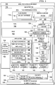
Figure 1 is an illustration of a manufacturing environment in the form of a block diagram in accordance with an illustrative embodiment; -
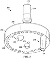
Figure 2 is an illustration of a bottom isometric view of a tool in accordance with an example useful for understanding the invention; -
Figure 3 is an illustration of a bottom isometric view of a tool in accordance with an example useful for understanding the invention; -
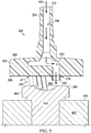
Figure 4 is an illustration of a cross-sectional view of a tool in accordance with an example useful for understanding the invention; -
Figure 5 is an illustration of another cross-sectional view of a tool in accordance with an example useful for understanding the invention; -
Figure 6 is an illustration of yet another cross-sectional view of a tool in accordance with an example useful for understanding the invention; -
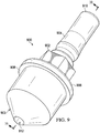
Figure 7 is in an illustration of a different type of tool accordance with an example useful for understanding the invention; -
Figure 8 is an illustration of a cross-sectional view of a tool in accordance with an example useful for understanding the invention; -
Figure 9 is an illustration of another type of tool in accordance with an example useful for understanding the invention; -
Figure 10 is an illustration of a cross-sectional view of a tool in accordance with an example useful for understanding the invention; -
Figure 11 is an illustration of another type of tool in accordance with an example useful for understanding the invention; -
Figure 12 is an illustration of a cross-sectional view of a tool in accordance with an example useful for understanding the invention; -
Figure 13 is an illustration of a tool connected to a portion of an end effector in accordance with an example useful for understanding the invention; -
Figure 14 is an illustration of a cross-sectional view of a tool and a portion of an end effector in accordance with an example useful for understanding the invention; -
Figure 15 is an illustration of a tool in accordance with an illustrative embodiment; -
Figure 16 is an illustration of a cross-sectional view of a tool in accordance with an illustrative embodiment; -
Figure 17 is an illustration of a bottom isometric cross-sectional view of a tool in accordance with an illustrative embodiment; -
Figure 18 is an illustration of a tool in accordance with an illustrative embodiment; -
Figure 19 is an illustration of a process for applying a fluid onto a number of surfaces in the form of a flowchart in accordance with an illustrative embodiment; -
Figure 20 is an illustration of a process for applying a fluid onto a number of surfaces in the form of a flowchart in accordance with an illustrative embodiment; -
Figure 21 is illustration of an aircraft manufacturing and service method in the form of a flowchart in accordance with an illustrative embodiment; and -
Figure 22 is an illustration of an aircraft in the form of a block diagram in accordance with an illustrative embodiment. - The illustrative embodiments recognize and take into account different considerations. For example, without limitation, the illustrative embodiments recognize and take into account that it may be desirable to have a tool that reduces the amount of time needed for applying sealant material, while simultaneously improving the ergonomics of using the tool and the quality of the application of the sealant material. Further, the illustrative embodiments recognize and take into account that attaching the tool to a robotic end effector configured to dispense sealant material may reduce the time needed for sealant application and improve the precision with which the sealant material may be applied.
- Thus, the illustrative embodiments provide a tool for applying sealant material onto one or more surfaces. In one illustrative embodiment, an apparatus may comprises a base having a number of channels, a number of flexible members extending from the base, and an applicator extending from the base on a same side as the number of flexible members. A flexible member in the number of flexible members may have a fluid channel connected to at least one of the number of channels in the base to allow a fluid flowing through the number of channels to flow out of the fluid channel. The applicator may be configured to apply the fluid flowing out of the number of flexible members onto a number of surfaces.
- Referring now to the figures and, in particular, with reference to
Figure 1 , an illustration of a manufacturing environment is depicted in the form of a block diagram in accordance with an illustrative embodiment. In this illustrative example,manufacturing environment 100 may be an example of an environment in whichtool 102 may be used to apply fluid 104 onto number ofsurfaces 106 of number ofobjects 108. - As used herein, a "number of" items may mean one or more items. In this manner, number of
surfaces 106 may include one or more surfaces. Similarly, number ofobjects 108 may include one or more objects. - In one illustrative example, number of
objects 108 may include a fastener element and an object in which the fastener element is installed. Number ofsurfaces 106 may include the surface of the exposed portion of the fastener element and the surface of the object around the fastener element. -
Fluid 104 may take a number of different forms. Depending on the implementation,fluid 104 may take the form ofsealant material 110,paste 111, or some other type of fluid. In this illustrative example, fluid 104 may haveviscosity 112 greater than selectedthreshold 113. Selectedthreshold 113 may be, for example, without limitation, about 500 centipoise. -
Fluid 104 may be dispensed totool 102 fromend effector 114.End effector 114 may be a device or system configured for attachment to, for example, without limitation, a robotic device. The robotic device may be a robotic arm in some cases. In this manner,end effector 114 may be referred to as a robotic end effector. - In this illustrative example,
end effector 114 may take the form offluid dispensing system 115.Fluid dispensing system 115 may includefluid source 116 and dispensingdevice 117. In some cases,fluid source 116 may be removably attached tofluid dispensing system 115.Fluid source 116 may be configured to holdfluid 104. For example, when fluid 104 takes the form ofsealant material 110,fluid source 116 may besealant cartridge 118 configured to holdsealant material 110. -
Dispensing device 117 may receive fluid 104 fromfluid source 116.Dispensing device 117 may be configured to dispense fluid 104 out ofexit 120 of dispensingdevice 117. In one illustrative example, dispensingdevice 117 may includenozzle 119 havingexit 120.Exit 120 may be an opening innozzle 119 through whichfluid 104leaves dispensing device 117. In other illustrative examples, dispensingdevice 117 may include a valve system for controlling the flow offluid 104 out of dispensingdevice 117 totool 102. - In this illustrative example,
tool 102 may includebase 122,applicator 124, number offlexible members 126, andconnector 128.Base 122 may havefirst side 123 andsecond side 125.First side 123 andsecond side 125 may be opposite sides ofbase 122. Further,base 122 may have number ofchannels 130 that extend fromfirst side 123 tosecond side 125.Connector 128 may be associated withbase 122 atfirst side 123 ofbase 122. As used herein, when one component is "associated" with another component, the association is a physical association in the depicted examples. - For example, without limitation, a first component, such as
connector 128, may be considered to be associated with a second component, such asbase 122, by being secured to the second component, bonded to the second component, mounted to the second component, welded to the second component, fastened to the second component, and/or connected to the second component in some other suitable manner. The first component also may be connected to the second component using a third component. Further, the first component may be considered to be associated with the second component by being formed as part of and/or as an extension of the second component. -
Connector 128 may be used to connect, or attach,tool 102 tofluid dispensing system 115. As depicted,connector 128 may havechannel 132.Connector 128 may be connected to dispensingdevice 117 offluid dispensing system 115 in a manner such thatfluid 104 flowing out ofexit 120 of dispensingdevice 117 flows intochannel 132 ofconnector 128. In this manner,connector 128 may be attached tofluid dispensing system 115 to fluidly connect dispensingdevice 117 toconnector 128. As a result,exit 120 of dispensingdevice 117 may be fluidly connected to channel 132 ofconnector 128. - Further,
connector 128 may be associated withfirst side 123 ofbase 122 such thatconnector 128 is fluidly connected tobase 122. In particular, fluid 104 flowing throughchannel 132 ofconnector 128 may flow into number ofchannels 130 ofbase 122.Channel 132 ofconnector 128 may be fluidly connected to number ofchannels 130 ofbase 122. -
Applicator 124 and number offlexible members 126 may extend from a same side ofbase 122, which may besecond side 125 in this illustrative example. As used herein, a "flexible member," such as one of number offlexible members 126 may be a structure comprised of any number of materials that allow the structure to have some flexibility. -
Flexible member 134 is an example of one of number offlexible members 126.Flexible member 134 may take the form offlexible tube 136 in one illustrative example.First end 135 offlexible member 134 may be associated withsecond side 125 ofbase 122, whilesecond end 137 offlexible member 134 may be exposed and located some distance away frombase 122. In this illustrative example,second end 137 may be an open end. - For example, without limitation,
flexible member 134 may be a hollow member havingfluid channel 138 that extends fromfirst end 135 tosecond end 137.Fluid channel 138 may be connected to at least one of number ofchannels 130 ofbase 122 to allow fluid 104 flowing through number ofchannels 130 to flow throughfluid channel 138 and out offluid channel 138 atsecond end 137.Fluid channel 138 may be fluidly connected to at least one of number ofchannels 130. In this illustrative example,second end 137 offluid channel 138 may not extend past the furthest tip ofapplicator 124. -
Applicator 124 may be used to apply fluid 104 that flows out offluid channel 138 onto at least one of number ofsurfaces 106. Further,applicator 124 may be used to apply fluid 104 that flows out of the fluid channel of each of number offlexible members 126 onto number ofsurfaces 106. - In particular,
applicator 124 may be moved over number ofsurfaces 106 in a manner that transfers at least a portion offluid 104 flowing out of number offlexible members 126 onto number ofsurfaces 106. For example, without limitation,tool 102 may be rotated such thatapplicator 124 is rotated over number ofsurfaces 106. In another example,applicator 124 may be moved in a sweeping motion over number ofsurfaces 106. -
Applicator 124 may be implemented in a number of different ways. For example, without limitation,applicator 124 may comprise at least one of number ofbrushes 140, number ofsponges 141, plurality ofbristles 142, plurality ofwires 143, plurality offilaments 144, or some other type of element or group of elements configured for use in applyingfluid 104 onto a surface. - In one illustrative example,
applicator 124 may comprise plurality ofbristles 142. In some illustrative examples, at least a portion of plurality ofbristles 142 may be angled relative to base 122 at an angle different from other bristles in plurality ofbristles 142. By angling the bristles in plurality ofbristles 142 at different angles, plurality ofbristles 142 may be able to apply fluid 104 onto surfaces having various shapes and/or geometries. - In another illustrative example, plurality of
bristles 142 may include first set ofbristles 146 and second set ofbristles 148. First set ofbristles 146 may be configured to extend tofirst position 150 located a first distance away frombase 122. Second set ofbristles 148 may be configured to extend tosecond position 152 located a second distance away frombase 122.First position 150 may be different frombase 122. In this manner, first set ofbristles 146 may be used to apply fluid 104 onto two different types of surfaces at the same time. - In yet another illustrative example, plurality of
bristles 142 may include first set ofbristles 146, second set ofbristles 148, and third set ofbristles 154. First set ofbristles 146, second set ofbristles 148, and third set ofbristles 154 may be configured to apply fluid 104 onto a first surface, a second surface, and a third surface, respectively, in number ofsurfaces 106. - In one illustrative example, first set of
bristles 146, second set ofbristles 148, and third set ofbristles 154 may extend frombase 122 atfirst angle 147,second angle 149, andthird angle 155, respectively.First angle 147,second angle 149, andthird angle 155 may all be different angles in this illustrative example. Further,first angle 147,second angle 149, andthird angle 155 may be selected for first set ofbristles 146, second set ofbristles 148, and third set ofbristles 154, respectively, based on the particular surface with which the set of bristles is to be used. - For example, without limitation,
first angle 147 for first set ofbristles 146 may be selected such that the ends, or tips, of first set ofbristles 146 contact a particular surface rather than the sides of first set ofbristles 146. In this manner, fluid 104 may be applied to this surface evenly and adequately. - When the sides of plurality of
bristles 142 touch a surface as opposed to ends 153 of plurality ofbristles 142, good agitation of plurality ofbristles 142 and coverage by plurality ofbristles 142 may not be achieved.Ends 153 of plurality ofbristles 142 may also be referred to as the tips of plurality ofbristles 142. Consequently, first set ofbristles 146, second set ofbristles 148, and third set ofbristles 154 may be angled relative to base 122 based on the surfaces to be contacted by these sets of bristles. - Further, the lengths of the bristles in plurality of
bristles 142 may be varied based on the angles of the bristles in plurality ofbristles 142 relative to base 122 to ensure that ends 153 of plurality ofbristles 142 contact number ofsurfaces 106. In particular, the lengths of plurality ofbristles 142 and the angles of plurality ofbristles 142 relative to base 122 may be varied such thatfluid 104 is applied onto number ofsurfaces 106 byends 153 of plurality ofbristles 142. - The illustration of
manufacturing environment 100 andtool 102 inFigure 1 is not meant to imply physical or architectural limitations to the manner in which an illustrative embodiment may be implemented. Other components in addition to or in place of the ones illustrated may be used. Some components may be optional. Also, the blocks are presented to illustrate some functional components. One or more of these blocks may be combined, divided, or combined and divided into different blocks when implemented in an illustrative embodiment. - In some illustrative examples, each bristle in plurality of
bristles 142 may extend frombase 122 at a different angle relative to the other bristles in plurality ofbristles 142. In this manner, different types of surfaces may be evenly and adequately coated withfluid 104 using plurality ofbristles 142. - With reference now to
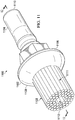
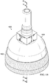
Figure 2 , an illustration of a bottom isometric view of a tool is depicted in accordance with an illustrative embodiment. In this illustrative example,tool 200 may be an example of one implementation fortool 102 inFigure 1 . As depicted,tool 200 may includebase 202,applicator 203, andconnector 204.Base 202,applicator 203, andconnector 204 may be examples of implementations forbase 122,applicator 124, andconnector 128, respectively, inFigure 1 . - In this illustrative example,
base 202 may havefirst side 206 andsecond side 208.Connector 204 may be associated with and extend fromfirst side 206 ofbase 202.End 210 ofconnector 204 may be used to connecttool 200 to an end effector (not shown), such asend effector 114 inFigure 1 . -
Applicator 203 may be associated with and extend fromsecond side 208 ofbase 202. In this illustrative example,applicator 203 may comprise plurality ofbristles 211. Plurality ofbristles 211 may be an example of one implementation for plurality ofbristles 142 inFigure 1 . - In this illustrative example, plurality of
bristles 211 may include bristles that are angled at different angles relative tobase 202. For example, bristle 212, bristle 214, and bristle 216 may all be angled at different angles relative tobase 202. Plurality ofbristles 211 may be angled relative to base 202 such that the exposed ends, or tips, of plurality ofbristles 211 may contact the surfaces selected for fluid application rather than the sides of plurality ofbristles 211. - As depicted, plurality of
bristles 211 may include bristles of varying lengths. The varying lengths of the bristles in plurality ofbristles 211 and the varying angles of the bristles in plurality ofbristles 211 relative to base 202 may ensure that fluid is applied evenly and with adequate coverage over selected surfaces. - In this illustrative example,
tool 200 may also include number offlexible tubes 218. Number offlexible tubes 218 may be an example of one implementation for number offlexible members 126 inFigure 1 . Number offlexible tubes 218 may includeflexible tubes bristles 211 ofapplicator 203. - With reference now to
Figure 3 , an illustration of a bottom isometric view oftool 200 fromFigure 2 is depicted in accordance with an illustrative embodiment.Applicator 203 with plurality ofbristles 211 fromFigure 2 is not shown in this view such that number offlexible tubes 218 may be more clearly seen. In this illustrative example, each offlexible tubes base 202. - Turning now to
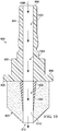
Figure 4 , an illustration of a cross-sectional view oftool 200 fromFigure 2 is depicted in accordance with an illustrative embodiment. In this illustrative example, a cross-sectional view oftool 200 fromFigure 2 is depicted taken along lines 4-4. -
Tool 200 may be used to apply a fluid, such asfluid 104 inFigure 1 , overfastener element 400 installed inobject 402.Fastener element 400 may havehead 403 exposed atsurface 404 ofobject 402.Tool 200 may also be used to apply the fluid over the portion ofsurface 404 around head - 403. As depicted,
connector 204 may havechannel 406, an example of one implementation forchannel 132 inFigure 1 . Further,base 202 may havechannel 408, an example of one implementation for a channel in number ofchannels 130 ofbase 122 inFigure 1 . - The cross-sectional view of
tool 200 is depicted such that onlyflexible tube 224 of number offlexible tubes 218 fromFigure 2 may be seen. In this illustrative example,flexible tube 224 may havefluid channel 410, an example of one implementation forfluid channel 138 inFigure 1 . A fluid may flow in the direction ofarrow 412 throughchannel 406, into and throughchannel 408, and into and out offluid channel 410.Applicator 203 may be rotated such that fluid flowing out offluid channel 410 may be applied oversurface 404 ofobject 402 byapplicator 203 asapplicator 203 rotates. - Turning now to
Figure 5 , an illustration of another cross-sectional view oftool 200 fromFigure 2 is depicted in accordance with an illustrative embodiment. In this illustrative example, a cross-sectional view oftool 200 fromFigure 2 is depicted taken along lines 5-5. - In this illustrative example, the cross-sectional view of
tool 200 is depicted such that onlyflexible tube 222 of number offlexible tubes 218 fromFigure 2 may be seen. In this illustrative example,flexible tube 222 may havefluid channel 500, an example of one implementation forfluid channel 138 inFigure 1 . Further,base 202 may havechannel 502, an example of one implementation for a channel in number ofchannels 130 inFigure 1 . - A fluid may flow in the direction of
arrow 503 throughchannel 406, into and throughchannel 502, and into and out offluid channel 500.Applicator 203 may be rotated such that fluid flowing out offluid channel 500 may be applied overtop surface 504 ofhead 403 offastener element 400 byapplicator 203 asapplicator 203 rotates. - Turning now to
Figure 6 , an illustration of yet another cross-sectional view oftool 200 fromFigure 2 is depicted in accordance with an illustrative embodiment. In this illustrative example, a cross-sectional view oftool 200 fromFigure 2 is depicted taken along lines 6-6. - In this illustrative example, the cross-sectional view of
tool 200 is depicted such that onlyflexible tube 220 of number offlexible tubes 218 fromFigure 2 may be seen. In this illustrative example,flexible tube 220 may havefluid channel 600, an example of one implementation forfluid channel 138 inFigure 1 . Further,base 202 may havechannel 602, an example of one implementation for a channel in number ofchannels 130 inFigure 1 . - A fluid may flow in the direction of
arrow 603 throughchannel 406, into and throughchannel 602, and into and out offluid channel 600.Applicator 203 may be rotated such that fluid flowing out offluid channel 600 may be applied overside surface 604 ofhead 403 offastener element 400 byapplicator 203 asapplicator 203 rotates. - With reference now to
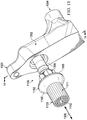
Figure 7 , an illustration of a different type of tool is depicted in accordance with an illustrative embodiment. In this illustrative example,tool 700 may be an example of one implementation fortool 102 inFigure 1 . As depicted,tool 700 may includebase 702,connector 704, andapplicator 703.Base 702,applicator 703, andconnector 704 may be examples of implementations forbase 122,applicator 124, andconnector 128, respectively, inFigure 1 . - In this illustrative example,
base 702 may havefirst side 706 andsecond side 708.Connector 704 may be associated with and extend fromfirst side 706 ofbase 702.End 710 ofconnector 704 may be used to connecttool 700 to an end effector (not shown), such asend effector 114 inFigure 1 . -
Applicator 703 may be associated with and extend fromsecond side 708 ofbase 702. In this illustrative example,applicator 703 may be implemented using a plurality of bristles (not individually shown in this figure). - Turning now to
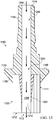
Figure 8 , an illustration of a cross-sectional view oftool 700 fromFigure 7 is depicted in accordance with an illustrative embodiment. In this illustrative example, a cross-sectional view oftool 700 fromFigure 7 is depicted taken along lines 8-8 inFigure 7 . - In
Figure 8 ,channel 800 ofconnector 704 may be seen.Channel 800 may be an example of one implementation forchannel 132 inFigure 1 . Further,channel 801 inbase 702 may be seen.Channel 801 may be an example of one implementation for number ofchannels 130 inFigure 1 . -
Tool 700 may also includeflexible tube 804 andflexible tube 806, an example of one implementation forflexible tube 136 inFigure 1 .Flexible tube 804 andflexible tube 806 may havefluid channel 805 andfluid channel 807, respectively. - In this illustrative example, a fluid (not shown) may flow in the direction of
arrow 808 throughchannel 800 ofconnector 704, into and throughchannel 801 ofbase 702, and into and out offluid channel 805 andfluid channel 807. - In this illustrative example,
flexible tube 804 andflexible tube 806 may not extendpast applicator 703. The bristles (not shown) that formapplicator 703 may all extend to asame position 810 away frombase 702. - With reference now to
Figure 9 , an illustration of another type of tool is depicted in accordance with an illustrative embodiment. In this illustrative example,tool 900 may be an example of one implementation fortool 102 inFigure 1 . As depicted,tool 900 may includebase 902,connector 904, andapplicator 903.Base 902,applicator 903, andconnector 904 may be examples of implementations forbase 122,applicator 124, andconnector 128, respectively, inFigure 1 . - In this illustrative example,
base 902 may havefirst side 906 andsecond side 908.Connector 904 may be associated with and extend fromfirst side 906 ofbase 902.End 910 ofconnector 904 may be used to connecttool 900 to an end effector (not shown), such asend effector 114 inFigure 1 . -
Applicator 903 may be associated with and extend fromsecond side 908 ofbase 902. In this illustrative example,applicator 903 may be implemented using a plurality of bristles (not individually shown in this figure).Applicator 903 may have opening 912 throughapplicator 903. - Turning now to
Figure 10 , an illustration of a cross-sectional view oftool 900 fromFigure 9 is depicted in accordance with an illustrative embodiment. In this illustrative example, a cross-sectional view oftool 900 fromFigure 9 is depicted taken along lines 10-10 inFigure 9 . - In
Figure 10 ,channel 1000 ofconnector 904 may be seen.Channel 1000 may be an example of one implementation forchannel 132 inFigure 1 . Further,channel 1001 inbase 902 may be seen.Channel 1001 may be an example of one implementation for number ofchannels 130 inFigure 1 . -
Tool 900 may also includeflexible tube 1004, an example of one implementation forflexible tube 136 inFigure 1 .Flexible tube 1004 may havefluid channel 1006. - In this illustrative example, a fluid (not shown) may flow in the direction of
arrow 1008 throughchannel 1000 ofconnector 904, into and throughchannel 1001 ofbase 902, and into and out offluid channel 1006. - In this illustrative example,
flexible tube 1004 may haveend 1010 that does not extendpast applicator 903. The bristles (not shown) that formapplicator 903 may extend to different positions away from base 922, as depicted. - With reference now to
Figure 11 , an illustration of another type of tool is depicted in accordance with an illustrative embodiment. In this illustrative example,tool 1100 may be an example of one implementation fortool 102 inFigure 1 . As depicted,tool 1100 may include base 1102,connector 1104, andapplicator 1103.Base 1102,applicator 1103, andconnector 1104 may be examples of implementations forbase 122,applicator 124, andconnector 128, respectively, inFigure 1 . - In this illustrative example,
base 1102 may havefirst side 1106 andsecond side 1108.Connector 1104 may be associated with and extend fromfirst side 1106 ofbase 1102.End 1110 ofconnector 1104 may be used to connecttool 1100 to an end effector (not shown), such asend effector 114 inFigure 1 . -
Applicator 1103 may be associated with and extend fromsecond side 1108 ofbase 1102. In this illustrative example,applicator 1103 may be implemented using plurality ofbristles 1111. Plurality ofbristles 1111 may be an example of one implementation for plurality ofbristles 142 inFigure 1 .Applicator 1103 may haveopening 1112 throughapplicator 1103. - Turning now to
Figure 12 , an illustration of a cross-sectional view oftool 1100 fromFigure 11 is depicted in accordance with an illustrative embodiment. In this illustrative example, a cross-sectional view oftool 1100 fromFigure 11 is depicted taken along lines 12-12 inFigure 11 . - In
Figure 12 ,channel 1200 ofconnector 1104 may be seen.Channel 1200 may be an example of one implementation forchannel 132 inFigure 1 . Further,channel 1201 inbase 1102 may be seen.Channel 1201 may be an example of one implementation for number ofchannels 130 inFigure 1 . -
Tool 1100 may also includeflexible tube 1204, an example of one implementation forflexible tube 136 inFigure 1 .Flexible tube 1204 may havefluid channel 1206. - In this illustrative example, a fluid (not shown) may flow in the direction of
arrow 1208 throughchannel 1200 ofconnector 1104, into and throughchannel 1201 ofbase 1102, and into and out offluid channel 1206. - In this illustrative example,
flexible tube 1204 may haveend 1210 that does not extendpast applicator 1103. The bristles (not shown) thatform applicator 1103 may extend to asame position 1212 away frombase 1102, as depicted. - With reference now to
Figure 13 , an illustration oftool 1100 fromFigures 11-12 connected to a portion of an end effector is depicted in accordance with an illustrative embodiment. In this illustrative example,connector 1104 may be used to connecttool 1100 to endeffector 1300.End effector 1300 may be an example of one implementation forend effector 114 inFigure 1 .End effector 1300 may include dispensingdevice 1302. -
Connector 1104 may be connected to endeffector 1300 such that a fluid (not shown) that enters dispensingdevice 1302 throughopening 1304 may exit dispensingdevice 1302 and flow intochannel 1200 inFigure 12 ofconnector 1104. -
End effector 1300 may be configured to rotatetool 1100 in a direction aroundaxis 1306 during fluid application operations. Fluid may flow out throughopening 1112 and be applied onto any number of surfaces astool 1100, and therebyapplicator 1103, is rotated. - Turning now to
Figure 14 , an illustration of a cross-sectional view oftool 1100 and the portion ofend effector 1300 seen inFigure 13 is depicted in accordance with an illustrative embodiment. In this illustrative example, a cross-sectional view oftool 1100 andend effector 1300 fromFigure 13 is depicted taken along lines 13-13 inFigure 11 . In this illustrative example, a fluid (not shown) may flow throughchannel 1400 in dispensingdevice 1302 in the direction ofarrow 1402 intochannel 1200 ofconnector 1104. - With reference now to
Figure 15 , an illustration of a tool is depicted in accordance with an illustrative embodiment. In this illustrative example,tool 1500 may be implemented in a manner similar to the manner in whichtool 102 fromFigure 1 is implemented. However,tool 1500 may havecover 1502 to cover the applicator (not shown) oftool 1500. -
Cover 1502 may help reduce the likelihood of a fluid being applied by the applicator from spraying onto undesired surfaces. In this illustrative example,cover 1502 may be formed as part of the structure that formsbase 1504 oftool 1500. In other words, cover 1502 may be a part of base - 1504. Turning now to
Figure 16 , an illustration of a cross-sectional view oftool 1500 fromFigure 15 withtool 1500 positioned over a fastener element is depicted in accordance with an illustrative embodiment. InFigure 16 , the cross-sectional view oftool 1500 fromFigure 15 is depicted taken along lines 16-16 inFigure 15 . As depicted,tool 1500 has been positioned overfastener element 1600.Fastener element 1600 may be an example of one implementation for an object in number ofobjects 108 inFigure 1 . - In this illustrative example,
tool 1500 may haveapplicator 1601 comprised of plurality ofbristles 1602 that may extend from base 1504 withinspace 1604 betweenbase 1504 andfastener element 1600.Applicator 1601 and plurality ofbristles 1602 may be an example of one implementation forapplicator 124 and plurality ofbristles 142, respectively, inFigure 1 . - As depicted, plurality of
bristles 1602 may extend from base 1504 at varying angles and may have varying lengths. The varying angles and lengths of the bristles in plurality ofbristles 1602 may be selected to ensure application of fluid overfastener element 1600 in a manner that meets selected tolerances. Further,flexible tube 1606 may be one flexible tube associated with base 1504 from which fluid may be dispensed. - With reference now to
Figure 17 , an illustration of a bottom isometric cross-sectional view oftool 1500 fromFigure 16 is depicted in accordance with an illustrative embodiment. In this illustrative example,base 1504 may haveinner walls 1700. More bristles in plurality ofbristles 1602 may be seen in this view. As depicted, plurality ofbristles 1602 may include bristles that are configured to contactfastener element 1600 as well as bristles that may be configured to contact a surface of an object (not shown) with whichfastener element 1600 may be associated. - With reference now to
Figure 18 , an illustration of a tool is depicted in accordance with an illustrative embodiment. In this illustrative example,tool 1800 may be implemented in a manner similar to the manner in whichtool 1500 fromFigure 15 is implemented. However,tool 1800 may havecover 1802 that is removably attached tobase 1804 oftool 1800. In other words, cover 1802 may be a component separate and independent of base 1804 in this illustrative example. -
Cover 1802 may help reduce the likelihood of a fluid being applied by the applicator from spraying onto undesired surfaces. In this illustrative example,cover 1802 may be comprised of one or more flexible materials. In one illustrative example,cover 1802 may be referred to as a shroud. - The illustrations of
tool 200 inFigures 2-6 ,tool 700 inFigures 7-8 ,tool 900 inFigures 9-10 ,tool 1100 inFigures 11-12 ,end effector 1300 inFigures 13-14 ,tool 1500 withcover 1502 inFigures 15-17 , andtool 1800 withcover 1802 inFigure 18 are not meant to imply physical or architectural limitations to the manner in which an illustrative embodiment may be implemented. Other components in addition to or in place of the ones illustrated may be used. Some components may be optional. - The different components shown in
Figures 2-18 may be illustrative examples of how components shown in block form inFigure 1 can be implemented as physical structures. Additionally, some of the components inFigures 2-18 may be combined with components inFigure 1 , used with components inFigure 1 , or a combination of the two. - With reference now to
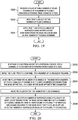
Figure 19 , an illustration of a process for applying fluid onto a number of surfaces is depicted in the form of a flowchart in accordance with an illustrative embodiment. The process illustrated inFigure 19 may be implemented usingtool 102 inFigure 1 . - The process may begin by receiving
fluid 104 within a number of fluid channels of number offlexible members 126 extending frombase 118 of tool 102 (operation 1900). Next, fluid 104 may be moved out of the number of fluid channels (operation 1902). Thereafter, fluid 104 may be applied onto number ofsurfaces 106 usingapplicator 124 extending frombase 122 on a same side as number of flexible members 126 (operation 1904), with the process terminating thereafter. - With reference now to
Figure 20 , an illustration of a process for applying fluid onto a number of surfaces is depicted in the form of a flowchart in accordance with an illustrative embodiment. The process illustrated inFigure 19 may be implemented usingtool 102 inFigure 1 . - The process may begin by dispensing fluid 104 from
exit 115 of dispensingdevice 117 intochannel 130 ofconnector 128 extending frombase 118 of tool 102 (operation 2000).Fluid 104 may then be moved fromchannel 132 into number ofchannels 130 in base 122 (operation 2002).Fluid 104 may be moved from number ofchannels 130 inbase 122 into a number of fluid channels of number offlexible members 126 extending frombase 122 oftool 102 on a side ofbase 122 opposite connector 128 (operation 2004). Thereafter, fluid 104 may be moved out of the number of fluid channels (operation 2006). - Next, fluid 104 may be applied onto number of
surfaces 106 using plurality ofbristles 142 extending frombase 122 on the same side as number offlexible members 126 in which bristles in plurality ofbristles 142 are angled relative tobase 122 such thatfluid 104 is applied onto number ofsurfaces 106 byends 153 of plurality of bristles 142 (operation 2008), with the process terminating thereafter. Inoperation 2008,fluid 104 that has moved out of the number of fluid channels may be applied onto number ofsurfaces 106 using the ends, or tips, of plurality ofbristles 142. In one illustrative example, the bristles in plurality ofbristles 142 may have different angles relative tobase 122 and/or different lengths that allow even and adequate application offluid 104 onto number ofsurfaces 106 such that the coverage of number ofsurfaces 106 byfluid 104 meets within selected tolerances. - The illustrative embodiments of the disclosure may be described in the context of aircraft manufacturing and
service method 2100 as shown inFigure 21 andaircraft 2200 as shown inFigure 22 . Turning first toFigure 21 , an illustration of an aircraft manufacturing and service method is depicted in the form of a flowchart in accordance with an illustrative embodiment. During pre-production, aircraft manufacturing andservice method 2100 may include specification anddesign 2102 ofaircraft 2200 inFigure 22 andmaterial procurement 2104. - During production, component and
subassembly manufacturing 2106 andsystem integration 2108 ofaircraft 2200 inFigure 22 takes place. Thereafter,aircraft 2200 inFigure 22 may go through certification anddelivery 2110 in order to be placed inservice 2112. While inservice 2112 by a customer,aircraft 2200 inFigure 22 is scheduled for routine maintenance andservice 2114, which may include modification, reconfiguration, refurbishment, and other maintenance or service. - Each of the processes of aircraft manufacturing and
service method 2100 may be performed or carried out by a system integrator, a third party, and/or an operator. In these examples, the operator may be a customer. For the purposes of this description, a system integrator may include, without limitation, any number of aircraft manufacturers and major-system subcontractors; a third party may include, without limitation, any number of vendors, subcontractors, and suppliers; and an operator may be an airline, a leasing company, a military entity, a service organization, and so on. - With reference now to
Figure 22 , an illustration of an aircraft is depicted in the form of a block diagram in which an illustrative embodiment may be implemented. In this example,aircraft 2200 is produced by aircraft manufacturing andservice method 2100 inFigure 21 and may includeairframe 2202 withsystems 2204 and interior 2206. Examples ofsystems 2204 include one or more ofpropulsion system 2208,electrical system 2210,hydraulic system 2212, andenvironmental system 2214. Any number of other systems may be included. Although an aerospace example is shown, different illustrative embodiments may be applied to other industries, such as the automotive industry. - Apparatuses and methods embodied herein may be employed during at least one of the stages of aircraft manufacturing and
service method 2100 inFigure 21 . In particular,fluid dispensing system 115 fromFigure 1 may be used for dispensing, for example, without limitation,sealant material 110, over various surfaces during any one of the stages of aircraft manufacturing andservice method 2100. For example, without limitation,tool 102 inFigure 1 may be used for applying sealant material onto surfaces withinaircraft 2200 during at least one of component andsubassembly manufacturing 2106,system integration 2108, routine maintenance andservice 2114, or some other stage of aircraft manufacturing andservice method 2100.Tool 102 fromFigure 1 may be used to apply sealant material onto surfaces ofairframe 2202 and/or interior 2200 ofaircraft 2200. - In one illustrative example, components or subassemblies produced in component and
subassembly manufacturing 2106 inFigure 21 may be fabricated or manufactured in a manner similar to components or subassemblies produced whileaircraft 2200 is inservice 2112 inFigure 21 . As yet another example, one or more apparatus embodiments, method embodiments, or a combination thereof may be utilized during production stages, such as component andsubassembly manufacturing 2106 andsystem integration 2108 inFigure 21 . One or more apparatus embodiments, method embodiments, or a combination thereof may be utilized whileaircraft 2200 is inservice 2112 and/or during maintenance andservice 2114 inFigure 21 . The use of a number of the different illustrative embodiments may substantially expedite the assembly of and/or reduce the cost ofaircraft 2200. - The flowcharts and block diagrams in the different depicted embodiments illustrate the architecture, functionality, and operation of some possible implementations of apparatuses and methods in an illustrative embodiment. In this regard, each block in the flowcharts or block diagrams may represent a module, a segment, a function, and/or a portion of an operation or step.
- In some alternative implementations of an illustrative embodiment, the function or functions noted in the blocks may occur out of the order noted in the figures. For example, without limitation, in some cases, two blocks shown in succession may be executed substantially concurrently, or the blocks may sometimes be performed in the reverse order, depending upon the functionality involved. Also, other blocks may be added in addition to the illustrated blocks in a flowchart or block diagram.
- The description of the different illustrative embodiments has been presented for purposes of illustration and description, and is not intended to be exhaustive or limited to the embodiments in the form disclosed. Many modifications and variations will be apparent to those of ordinary skill in the art. Further, different illustrative embodiments may provide different features as compared to other desirable embodiments. The embodiment or embodiments selected are chosen and described in order to best explain the principles of the embodiments, the practical application, and to enable others of ordinary skill in the art to understand the disclosure for various embodiments with various modifications as are suited to the particular use contemplated.
Claims (12)
- An apparatus comprising:a base (122, 202, 702, 902, 1102, 1504, 1804) having a number of channels (130, 408, 502, 602, 801, 1001, 1201);a number of flexible members (126) extending from the base (122, 202, 702, 902, 1102, 1504, 1804) in which each flexible member in the number of flexible members (126) has a fluid channel (138, 410, 500, 600, 805, 807, 1006, 1206) connected to at least one of the number of channels (130, 408, 502, 602, 801, 1001, 1201) in the base (122, 202, 702, 902, 1102, 1504, 1804) to allow a fluid (104) flowing through the number of channels (130, 408, 502, 602, 801, 1001, 1201) to flow out of the fluid channel (138, 410, 500, 600, 805, 807, 1006, 1206); andan applicator (124, 203, 703, 903, 1103, 1601) comprising a plurality of bristles (142, 211, 111, 1602), and extending from the base (122, 202, 702, 902, 1102, 1504, 1804) on a same side as the number of flexible members (126) and configured to apply the fluid (104) flowing out of the number of flexible members (126) onto a number of surfaces, wherein the plurality of bristles (142, 211, 111, 1602) includes:a first set of bristles extending to a first position located a first distance away from the base (122, 202, 702, 902, 1102, 1504, 1804); anda second set of bristles extending to a second position located a second distance away from the base (122, 202, 702, 902, 1102, 1504, 1804);wherein the base (122, 202, 702, 902, 1102, 1504, 1804) further comprises a cover (1502, 1802) configured to reduce the likelihood of fluid (104) applied by the applicator (124, 203, 703, 903, 1103, 1601) from spraying onto undesired surfaces.
- The apparatus of claim 1, wherein at least one of the plurality of bristles is angled relative to the base (122, 202, 702, 902, 1102, 1504, 1804) at an angle different from other bristles in the plurality of bristles (142, 211, 111, 1602).
- The apparatus of either claim 1 or claim 2, wherein the plurality of bristles (142, 211, 111, 1602) includes:a first set of bristles configured to apply the fluid (104) onto a first surface in the number of surfaces;a second set of bristles configured to apply the fluid (104) onto a second surface in the number of surfaces; anda third set of bristles configured to apply the fluid (104) onto a third surface in the number of surfaces.
- The apparatus of any preceding claim further comprising:a connector associated with the base (122, 202, 702, 902, 1102, 1504, 1804) and having a channel configured to connect the number of channels in the base (122, 202, 702, 902, 1102, 1504, 1804) to an exit of a dispensing device on a side of the base (122, 202, 702, 902, 1102, 1504, 1804) opposite the applicator (124, 203, 703, 903, 1103, 1601).
- The apparatus of any preceding claim, wherein each flexible member (126) in the number of flexible members (126) has an end that does not extend past the applicator (124, 203, 703, 903, 1103, 1601).
- The apparatus of any preceding claim, wherein the applicator (124, 203, 703, 903, 1103, 1601) comprises:at least one of a number of brushes (140), a number of sponges (141), a plurality of wires (143), or a plurality of filaments (144).
- The apparatus of any preceding claim, wherein the fluid (104) is a sealant material having a viscosity greater than a selected threshold, wherein the selected threshold is about 500 centipoise.
- A method for applying a fluid (104) onto a number of surfaces, the method comprising:receiving the fluid (104) within a number of fluid channels (138, 410, 500, 600, 805, 807, 1006, 1206) of a number of flexible members (126) extending from a base (122, 202, 702, 902, 1102, 1504, 1804);moving the fluid (104) out of the number of fluid channels (138, 410, 500, 600, 805, 807, 1006, 1206); andapplying the fluid (104) onto the number of surfaces using an applicator (124, 203, 703, 903, 1103, 1601) comprising a plurality of bristles (142, 211, 111, 1602) extending from the base (122, 202, 702, 902, 1102, 1504, 1804) on a same side as the number of flexible members (126), wherein the plurality of bristles (142, 211, 111, 1602) includes:a first set of bristles extending to a first position located a first distance away from the base (122, 202, 702, 902, 1102, 1504, 1804); anda second set of bristles extending to a second position located a second distance away from the base (122, 202, 702, 902, 1102, 1504, 1804), wherein the base (122, 202, 702, 902, 1102, 1504, 1804) has a cover (1502, 1802) configured to reduce the likelihood of fluid (104) applied by the applicator (124, 203, 703, 903, 1103, 1601) from spraying onto undesired surfaces.
- The method of claim 8, wherein applying the fluid (104) onto the number of surfaces using the plurality of bristles (142, 211, 111, 1602) comprises:applying the fluid (104) onto the number of surfaces using ends of the plurality of bristles (142, 211, 111, 1602).
- The method of either claim 8 or claim 9, wherein applying the fluid (104) onto the number of surfaces using the applicator (124, 203, 703, 903, 1103, 1601) comprises:applying the fluid (104) onto a first surface in the number of surfaces using a first set of bristles in the plurality of bristles (142, 211, 111, 1602);applying the fluid (104) onto a second surface in the number of surfaces using a second set of bristles in the plurality of bristles (142, 211, 111, 1602); andapplying the fluid (104) onto a third surface in the number of surfaces using a third set of bristles in the plurality of bristles (142, 211, 111, 1602).
- The method of any of claims 8 to 10 further comprising:receiving the fluid (104) within a channel in a connector associated with the base (122, 202, 702, 902, 1102, 1504, 1804) from an exit of a dispensing device.
- The method of any of claims 8 to 11, wherein applying the fluid (104) onto the number of surfaces using the applicator (124, 203, 703, 903, 1103, 1601) comprises:applying the fluid (104) onto the number of surfaces using at least one of a number of brushes (140), a number of sponges (141), a plurality of wires (143), or a plurality of filaments (144).
Applications Claiming Priority (1)
| Application Number | Priority Date | Filing Date | Title |
|---|---|---|---|
| US14/016,846 US20150064357A1 (en) | 2013-09-03 | 2013-09-03 | Tool for Applying a Fluid onto a Surface |
Publications (2)
| Publication Number | Publication Date |
|---|---|
| EP2842457A1 EP2842457A1 (en) | 2015-03-04 |
| EP2842457B1 true EP2842457B1 (en) | 2018-01-10 |
Family
ID=51033083
Family Applications (1)
| Application Number | Title | Priority Date | Filing Date |
|---|---|---|---|
| EP14175644.5A Active EP2842457B1 (en) | 2013-09-03 | 2014-07-03 | Tool for applying a fluid |
Country Status (8)
| Country | Link |
|---|---|
| US (2) | US20150064357A1 (en) |
| EP (1) | EP2842457B1 (en) |
| JP (1) | JP6362962B2 (en) |
| KR (1) | KR101861405B1 (en) |
| CN (2) | CN108523397B (en) |
| CA (1) | CA2858185C (en) |
| ES (1) | ES2665593T3 (en) |
| PT (1) | PT2842457T (en) |
Cited By (1)
| Publication number | Priority date | Publication date | Assignee | Title |
|---|---|---|---|---|
| US11090677B2 (en) | 2015-10-15 | 2021-08-17 | The Boeing Company | methods for applying glutinous substances |
Families Citing this family (22)
| Publication number | Priority date | Publication date | Assignee | Title |
|---|---|---|---|---|
| US10105725B2 (en) | 2013-02-18 | 2018-10-23 | The Boeing Company | Fluid application device |
| US9757759B2 (en) | 2013-08-09 | 2017-09-12 | The Boeing Company | Method and apparatus for concurrently dispensing and fairing high viscosity fluid |
| US10525603B2 (en) | 2013-08-22 | 2020-01-07 | The Boeing Company | Method and apparatus for exchanging nozzles and tips for a fluid dispensing system |
| US20150064357A1 (en) | 2013-09-03 | 2015-03-05 | The Boeing Company | Tool for Applying a Fluid onto a Surface |
| US9439502B2 (en) | 2014-02-13 | 2016-09-13 | The Boeing Company | Handheld tool for applying a fluid onto a surface |
| ES2647822T3 (en) * | 2014-12-22 | 2017-12-26 | Kuka Systems Aerospace | Fluid application device |
| US9968962B2 (en) | 2015-03-19 | 2018-05-15 | The Boeing Company | Material applicator comprising a surface interface guide forming a continuous ring shaped flow channel with an unobstructive guding assembly therein |
| EP3106235A1 (en) * | 2015-06-19 | 2016-12-21 | Designetics, Inc. | Application of substance to protrusion |
| EP3127620B1 (en) * | 2015-08-07 | 2018-10-10 | Airbus Operations GmbH | Device and method for applying a liquid coating material to a portion of a fastening element |
| US10987693B2 (en) | 2015-08-18 | 2021-04-27 | The Boeing Company | Sealant application tip |
| US10524562B2 (en) * | 2015-10-15 | 2020-01-07 | The Boeing Company | Brushes for delivering glutinous substance to workpiece from end-effector |
| US10441067B2 (en) | 2015-10-15 | 2019-10-15 | The Boeing Company | Brushes for delivering glutinous substance to workpiece from end-effector |
| US10363569B2 (en) * | 2015-10-15 | 2019-07-30 | The Boeing Company | Applicators and systems for delivering a glutinous substance to a workpiece from an end-effector |
| CN105618335B (en) * | 2015-11-05 | 2018-02-16 | 浙江义利汽车零部件有限公司 | Engine cylinder cap oil hole oiling station |
| US10465711B2 (en) * | 2016-10-18 | 2019-11-05 | The Boeing Company | Apparatus and methods to deploy a fluid flow channel |
| US10486343B2 (en) * | 2017-03-27 | 2019-11-26 | The Boeing Company | Methods of applying materials over fastener heads protruding from non-horizontal surfaces |
| US11504853B2 (en) | 2017-11-16 | 2022-11-22 | General Electric Company | Robotic system architecture and control processes |
| US10060857B1 (en) | 2017-11-16 | 2018-08-28 | General Electric Company | Robotic feature mapping and motion control |
| US10772419B2 (en) * | 2018-04-10 | 2020-09-15 | Michael McArdle | Cleaning assembly |
| EP3613512A1 (en) * | 2018-08-14 | 2020-02-26 | Bombardier Inc. | Foam coating tool and coating method |
| US11135612B2 (en) * | 2019-03-19 | 2021-10-05 | The Boeing Company | Rotating applicators having fluid dispensers |
| US11879489B2 (en) * | 2019-07-02 | 2024-01-23 | Lisa Dräxlmaier GmbH | Method for covering a screw head in a sealed manner |
Family Cites Families (122)
| Publication number | Priority date | Publication date | Assignee | Title |
|---|---|---|---|---|
| US1003650A (en) * | 1909-10-16 | 1911-09-19 | Claus G Peterson | Brush. |
| US1988557A (en) * | 1932-02-05 | 1935-01-22 | Jecker Rudolf | Combined toothbrush and paste container |
| US1909146A (en) * | 1932-04-27 | 1933-05-16 | Collonus N Bohanan | Combination shaving brush and soap container |
| US2126999A (en) * | 1936-03-21 | 1938-08-16 | William M Clark | Fountain paint brush device |
| US2227792A (en) * | 1938-02-19 | 1941-01-07 | Norton Auto Flow Brush Corp | Brush |
| US2608705A (en) * | 1946-08-03 | 1952-09-02 | John R Duff | Golf ball cleaner |
| US2609974A (en) | 1950-04-19 | 1952-09-09 | Food Eng | Disposable plastic valve |
| US2824443A (en) | 1954-12-20 | 1958-02-25 | George W Williams | Corner-finishing tool head for applying mastic |
| US2978722A (en) * | 1957-08-14 | 1961-04-11 | Kusakabe Hisao | Tube container |
| US3378331A (en) * | 1965-10-19 | 1968-04-16 | Miracle Products Inc | Shaving brush device |
| US3661679A (en) | 1970-09-08 | 1972-05-09 | Lockwood Tech | Adhesive applicator for plywood patching machine |
| US3746253A (en) | 1970-09-21 | 1973-07-17 | Walberg & Co A | Coating system |
| US3865525A (en) | 1972-06-26 | 1975-02-11 | Owens Corning Fiberglass Corp | Apparatus for coating three dimensional objects |
| JPS4929616A (en) | 1972-07-12 | 1974-03-16 | ||
| FR2230168A5 (en) | 1973-05-18 | 1974-12-13 | Pont A Mousson | |
| US3888421A (en) | 1974-04-22 | 1975-06-10 | Beatrice Foods Co | Gun type fluid control device |
| US3963180A (en) | 1975-08-11 | 1976-06-15 | Spray Tech Corporation | Airless gun nozzle guard |
| JPS52142747A (en) | 1976-05-24 | 1977-11-28 | Mitsubishi Heavy Ind Ltd | Method for coating inner surface of steel pipes and equipment for the same |
| GB2012575B (en) * | 1977-11-12 | 1982-10-13 | Reckitt & Colmann Prod Ltd | Applicators for dispensing containers |
| SE430128B (en) | 1978-04-11 | 1983-10-24 | Atlas Copco Ab | TIRE PROTECTOR AT HIGH PRESSURE GUN |
| FR2508350A1 (en) * | 1981-06-29 | 1982-12-31 | Clayton Erith | Portable mechanical plating device - with brushes or absorbent pads movable relative to workpiece surface |
| JPS609873B2 (en) | 1981-08-11 | 1985-03-13 | 日本ゴム株式会社 | Application method to steel plate coated with anti-corrosion oil |
| JPS5924172U (en) | 1982-08-06 | 1984-02-15 | 関東自動車工業株式会社 | Adhesive automatic applicator |
| EP0106387B1 (en) | 1982-09-23 | 1986-12-30 | Evode Limited | Apparatus for extruding a fillet |
| JPH0230059Y2 (en) | 1984-10-03 | 1990-08-13 | ||
| DE3575333D1 (en) | 1984-10-15 | 1990-02-15 | Ltv Aerospace & Defence | METHOD AND DEVICE FOR APPLYING A SPECIFIC QUANTITY OF SEALANT TO UNprotected FASTENERS. |
| US4635827A (en) | 1985-02-06 | 1987-01-13 | Grumman Aerospace Corporation | Sealant applicator for rivet machine |
| JPS60241968A (en) * | 1985-04-09 | 1985-11-30 | Sunstar Giken Kk | Coating method of paint |
| JPS61187269U (en) | 1985-05-10 | 1986-11-21 | ||
| JPS625856U (en) | 1985-06-26 | 1987-01-14 | ||
| JPS62148379U (en) | 1986-03-10 | 1987-09-19 | ||
| US4948016A (en) | 1986-08-11 | 1990-08-14 | Sashco, Inc. | Laminated materials container |
| US4925061A (en) | 1987-05-06 | 1990-05-15 | Milbar Corporation | Fluid actuated dispenser |
| JPH0195269U (en) | 1987-12-18 | 1989-06-23 | ||
| EP0329813A1 (en) | 1988-02-26 | 1989-08-30 | Nordson Corporation | Valve arrangement for intermittently applying a liquid glue to a surface |
| DE58902717D1 (en) | 1988-04-20 | 1992-12-17 | Lenhardt Maschinenbau | DEVICE FOR DELIVERING HIGH VISCOSITY, PASTOESER, COMPRESSIBLE SUBSTANCES. |
| US5017113A (en) | 1988-05-02 | 1991-05-21 | Heaton Donald E | Filleting attachment for a caulking gun |
| US4932094A (en) | 1988-12-22 | 1990-06-12 | The Boeing Company | Liquid applicator tool |
| US5060869A (en) | 1989-10-10 | 1991-10-29 | Wagner Spray Tech Corporation | Ceramic flat spray tip |
| JPH0395697U (en) | 1990-01-11 | 1991-09-30 | ||
| JPH0438459A (en) | 1990-06-01 | 1992-02-07 | Kumamoto Techno Porisu Zaidan | Apparatus to inspect article |
| JPH0483549A (en) | 1990-07-25 | 1992-03-17 | Toyota Motor Corp | Multicolor coating device |
| IT1243378B (en) | 1990-07-27 | 1994-06-10 | Loctite Corp | PROCEDURE AND PLANT FOR THE DISPENSING PARTICULARLY OF A SEALANT / ADHESIVE PRODUCT |
| US5186563A (en) * | 1991-01-07 | 1993-02-16 | Gebhard Patricia A | Fluid dispenser with applicator member |
| US5271521A (en) | 1991-01-11 | 1993-12-21 | Nordson Corporation | Method and apparatus for compensating for changes in viscosity in a two-component dispensing system |
| US5319568A (en) | 1991-07-30 | 1994-06-07 | Jesco Products Co., Inc. | Material dispensing system |
| JPH05154428A (en) | 1991-12-11 | 1993-06-22 | Toshiba Corp | Dispenser device |
| US5271537A (en) | 1992-08-14 | 1993-12-21 | Johnson Charles W | Foam dispensing device |
| EP0599087B1 (en) * | 1992-11-27 | 1996-01-10 | Satzinger GmbH & Co. | Device for lubricating and cleaning of chains and rails |
| US5346380A (en) | 1993-09-22 | 1994-09-13 | Ables James T | Caulking tube extension nozzle |
| FR2710864B1 (en) | 1993-10-06 | 1995-12-08 | Pont A Mousson | Method and installation for assembling parts of gasifiable models used in foundries. |
| DE69509373T2 (en) | 1994-02-18 | 1999-08-26 | Itw Ltd | Spray gun with permanently attached spray head |
| US5615804A (en) | 1994-06-23 | 1997-04-01 | Insta-Foam Products, Inc. | Gun for dispensing fluent sealants or the like |
| US5687092A (en) | 1995-05-05 | 1997-11-11 | Nordson Corporation | Method of compensating for changes in flow characteristics of a dispensed fluid |
| US5571538A (en) | 1995-07-17 | 1996-11-05 | Cloud; Donald E. | Grout sealant applicator |
| US5819983A (en) | 1995-11-22 | 1998-10-13 | Camelot Sysems, Inc. | Liquid dispensing system with sealing augering screw and method for dispensing |
| US6082587A (en) | 1996-04-10 | 2000-07-04 | Automatic Bar Controls, Inc. | Condiment dispensing system utilizing a draw-back valve |
| US5906296A (en) | 1996-04-10 | 1999-05-25 | Automatic Bar Controls, Inc. | Condiment dispensing system utilizing a draw-back valve |
| JPH09314305A (en) | 1996-05-31 | 1997-12-09 | Ube Ind Ltd | Die spray robot |
| US5848458A (en) | 1997-05-15 | 1998-12-15 | Northrop Grumman Corporation | Reconfigurable gantry tool |
| US6001181A (en) | 1997-08-01 | 1999-12-14 | Northrop Grumman Corporation | Automated sealant applicator |
| US5976631A (en) | 1997-08-29 | 1999-11-02 | E. I. Du Pont De Nemours And Company | Viscous liquid applicator method |
| US5992686A (en) | 1998-02-27 | 1999-11-30 | Fluid Research Corporation | Method and apparatus for dispensing liquids and solids |
| JPH11262717A (en) | 1998-03-17 | 1999-09-28 | Asahi Glass Co Ltd | Method and device for applying adhesive to surface of platelike body held vertically |
| ATE454940T1 (en) | 1999-05-07 | 2010-01-15 | Designetics | AUTOMATIC PRIMER STATION |
| US6213354B1 (en) | 1999-12-29 | 2001-04-10 | Elite Engineering Corporation | System and method for dispensing fluid droplets of known volume and generating very low fluid flow rates |
| US6705537B2 (en) | 2000-05-05 | 2004-03-16 | Sealant Equipment & Engineering, Inc. | Orbital applicator tool with self-centering dispersing head |
| EP1174193A1 (en) | 2000-07-18 | 2002-01-23 | Loctite (R & D) Limited | A dispensing nozzle |
| JP3340423B2 (en) | 2000-08-11 | 2002-11-05 | 川崎重工業株式会社 | Nozzle holder |
| JP2002192345A (en) | 2000-12-25 | 2002-07-10 | Sekisui Chem Co Ltd | Changing apparatus of welding nozzles and chips |
| JP3507036B2 (en) * | 2001-01-18 | 2004-03-15 | 株式会社呉竹 | Writing implement |
| JP2002280798A (en) | 2001-03-22 | 2002-09-27 | Yamagata Casio Co Ltd | Nozzle type recognition control method, nozzle contamination recognition control method, and electronic component placement apparatus using the control methods |
| DE10115467A1 (en) | 2001-03-29 | 2002-10-02 | Duerr Systems Gmbh | Tool changing system for one machine |
| DE10115470A1 (en) | 2001-03-29 | 2002-10-10 | Duerr Systems Gmbh | Coating system with an atomizer change station |
| US7037289B2 (en) | 2001-09-12 | 2006-05-02 | 3M Innovative Properties Company | Apparatus and methods for dispensing an adhesive tissue sealant |
| JP2003242469A (en) | 2002-02-21 | 2003-08-29 | Daishowa Seiki Co Ltd | Information holding body |
| GB0205893D0 (en) | 2002-03-13 | 2002-04-24 | Otv Sa | Water purification apparatus |
| US6698617B1 (en) | 2002-09-13 | 2004-03-02 | Ford Motor Company | System and method of changing a disposable nozzle tip for dispensing reactant mixtures |
| EP1554056B1 (en) | 2002-10-23 | 2008-06-11 | Fanuc Robotics America, Inc. | Robotic apparatus for painting |
| CA2515683A1 (en) | 2003-02-21 | 2004-09-02 | Honda Motor Co., Ltd. | Coating system for protective layer forming material |
| DE102004027789B4 (en) | 2003-06-11 | 2011-12-08 | Martin Ruda | Replaceable paint spray facility and spray gun |
| US7592033B2 (en) | 2003-07-08 | 2009-09-22 | Computrol, Inc | Variable fluid dispenser |
| DE10335146B4 (en) | 2003-07-31 | 2006-02-09 | Fraunhofer-Gesellschaft zur Förderung der angewandten Forschung e.V. | Apparatus and method for the metered dispensing of a viscous medium |
| US6942736B2 (en) | 2003-08-25 | 2005-09-13 | Michael Chinander | Automatically controlled flow applicator |
| JP2005138260A (en) | 2003-11-10 | 2005-06-02 | I-Pulse Co Ltd | Suction nozzle, machine for mounting component, and apparatus for inspecting component |
| US7032839B2 (en) | 2003-12-30 | 2006-04-25 | 3M Innovative Properties Company | Liquid spray gun with manually separable portions |
| US7275663B2 (en) | 2004-04-20 | 2007-10-02 | Black & Decker Inc. | Dispensing device using multiple gas cartridges |
| US6935541B1 (en) | 2004-08-17 | 2005-08-30 | Black & Decker Inc. | Caulk gun pressurizing system |
| CN2715859Y (en) * | 2004-08-19 | 2005-08-10 | 卞菊香 | Multifunctional white latex squeegee |
| DE102004042211A1 (en) | 2004-09-01 | 2006-03-02 | Dr.Ing.H.C. F. Porsche Ag | Adhesive applying device for beats of paste-like substance, has holder with adhesive and designed as closed adhesive pistol, where pressure subjection of adhesive takes place by direct admission of cartridge base with pressurizing medium |
| DE202005005619U1 (en) | 2004-09-29 | 2006-02-02 | Langer, Peter | Micro metering valve for proportioning very small liquid quantities has tappet that is movable opposite closing direction to hit impact body |
| US7172096B2 (en) | 2004-11-15 | 2007-02-06 | Advanced Technology Materials, Inc. | Liquid dispensing system |
| US7588642B1 (en) | 2004-11-29 | 2009-09-15 | Advanced Cardiovascular Systems, Inc. | Abluminal stent coating apparatus and method using a brush assembly |
| US7101107B1 (en) * | 2005-04-29 | 2006-09-05 | Young Kwang Byun | Cosmetics brush |
| MX366436B (en) | 2005-10-21 | 2019-07-08 | Ch & I Tech Inc | Integrated material transfer and dispensing system. |
| US8430592B2 (en) * | 2006-06-01 | 2013-04-30 | Tote Connection, Inc. | Powered painting system |
| CA2882518C (en) | 2006-07-07 | 2019-08-27 | Fair Oaks Farms Brands, Inc. | Liquid food dispenser system and method |
| KR100669447B1 (en) | 2006-09-27 | 2007-01-16 | (주)에스에프시 | Hair cosmatic of supply apparatus a hair brush |
| US7922107B2 (en) | 2007-07-25 | 2011-04-12 | Fox Jeffrey D | Spray gun with paint cartridge |
| DE202007019244U1 (en) | 2007-08-02 | 2011-08-26 | Kuka Systems Gmbh | Machining equipment and manufacturing plant |
| DE102007053073A1 (en) | 2007-11-07 | 2009-06-04 | Dürr Systems GmbH | application system |
| DE102008010169A1 (en) | 2008-02-20 | 2009-09-03 | Herpa Miniaturmodelle Gmbh | Liquid i.e. color, spraying device, has needle projecting axially from needle holder in axial direction, and channels formed between needle and needle holder, and between needle and nozzle body for passing liquid from nozzle body to outlet |
| US7815132B2 (en) | 2008-08-12 | 2010-10-19 | Illinois Tool Works Inc. | Method for preventing voltage from escaping fluid interface for water base gravity feed applicators |
| EP2396236A1 (en) | 2009-02-12 | 2011-12-21 | Illinois Tool Works Inc. | Removable nozzle |
| EP2277631B1 (en) | 2009-07-21 | 2012-11-21 | HOLZ-HER GmbH | Adhesive application device |
| JP4604127B2 (en) | 2009-09-30 | 2010-12-22 | 富士機械製造株式会社 | Electronic circuit component mounting machine and electronic circuit assembly method |
| US8453876B2 (en) | 2009-12-07 | 2013-06-04 | Fluid Management Operations Llc | Colorant recirculation and dispense valve |
| JP2011179468A (en) | 2010-03-03 | 2011-09-15 | Dow Corning Toray Co Ltd | Dispenser for high viscosity fluid |
| WO2011152927A1 (en) * | 2010-06-04 | 2011-12-08 | Zen Design Solutions Limited | Cosmetic applicator |
| US20110311730A1 (en) * | 2010-06-18 | 2011-12-22 | The Boeing Company | Sealant Application Tool |
| DE102010030375A1 (en) * | 2010-06-23 | 2011-12-29 | Robert Bosch Gmbh | Hand-held paint applicator |
| CN101858456B (en) | 2010-07-02 | 2012-12-05 | 宜昌江峡船用机械有限责任公司 | Combination solenoid valve |
| US8651046B1 (en) | 2010-07-23 | 2014-02-18 | The Boeing Company | Robotic sealant and end effector |
| JP2012232660A (en) | 2011-04-28 | 2012-11-29 | Mitsubishi Heavy Ind Ltd | Sealant applicator, and method for applying sealant and method for assembling aircraft using the sealant applicator |
| DK2543277T3 (en) * | 2011-07-06 | 2016-10-03 | Braun Gmbh | CLEANING SECTION FOR AN ELECTRICAL ORAL HYGIENE DEVICE |
| RU2594413C2 (en) | 2012-01-27 | 2016-08-20 | ЗУЛЬЦЕР МЕТКО (ЮЭс), ИНК. | Gun for thermal spraying with removable nozzle tip and method for its production and use |
| US10105725B2 (en) | 2013-02-18 | 2018-10-23 | The Boeing Company | Fluid application device |
| US9016530B2 (en) | 2013-05-03 | 2015-04-28 | The Boeing Company | Control valve having a disposable valve body |
| US9095872B2 (en) | 2013-07-26 | 2015-08-04 | The Boeing Company | Feedback control system for performing fluid dispensing operations |
| US9757759B2 (en) | 2013-08-09 | 2017-09-12 | The Boeing Company | Method and apparatus for concurrently dispensing and fairing high viscosity fluid |
| US10525603B2 (en) | 2013-08-22 | 2020-01-07 | The Boeing Company | Method and apparatus for exchanging nozzles and tips for a fluid dispensing system |
| US20150064357A1 (en) | 2013-09-03 | 2015-03-05 | The Boeing Company | Tool for Applying a Fluid onto a Surface |
-
2013
- 2013-09-03 US US14/016,846 patent/US20150064357A1/en not_active Abandoned
-
2014
- 2014-07-03 ES ES14175644.5T patent/ES2665593T3/en active Active
- 2014-07-03 EP EP14175644.5A patent/EP2842457B1/en active Active
- 2014-07-03 PT PT141756445T patent/PT2842457T/en unknown
- 2014-07-16 KR KR1020140089520A patent/KR101861405B1/en active IP Right Grant
- 2014-07-31 CA CA2858185A patent/CA2858185C/en active Active
- 2014-08-20 JP JP2014167067A patent/JP6362962B2/en active Active
- 2014-09-02 CN CN201810430657.XA patent/CN108523397B/en active Active
- 2014-09-02 CN CN201410443281.8A patent/CN104415878B/en active Active
-
2016
- 2016-02-29 US US15/057,090 patent/US10086402B2/en active Active
Non-Patent Citations (1)
| Title |
|---|
| None * |
Cited By (1)
| Publication number | Priority date | Publication date | Assignee | Title |
|---|---|---|---|---|
| US11090677B2 (en) | 2015-10-15 | 2021-08-17 | The Boeing Company | methods for applying glutinous substances |
Also Published As
| Publication number | Publication date |
|---|---|
| PT2842457T (en) | 2018-04-10 |
| US10086402B2 (en) | 2018-10-02 |
| CN104415878B (en) | 2018-05-18 |
| CN104415878A (en) | 2015-03-18 |
| CA2858185A1 (en) | 2015-03-03 |
| KR20150026798A (en) | 2015-03-11 |
| KR101861405B1 (en) | 2018-07-02 |
| CN108523397A (en) | 2018-09-14 |
| CA2858185C (en) | 2017-08-22 |
| EP2842457A1 (en) | 2015-03-04 |
| JP2015047602A (en) | 2015-03-16 |
| US20160175883A1 (en) | 2016-06-23 |
| US20150064357A1 (en) | 2015-03-05 |
| ES2665593T3 (en) | 2018-04-26 |
| JP6362962B2 (en) | 2018-07-25 |
| CN108523397B (en) | 2020-09-29 |
Similar Documents
| Publication | Publication Date | Title |
|---|---|---|
| EP2842457B1 (en) | Tool for applying a fluid | |
| US11260412B2 (en) | Fluid application device | |
| US9016530B2 (en) | Control valve having a disposable valve body | |
| EP2837430B1 (en) | High-viscosity sealant application system | |
| US9643201B2 (en) | High viscosity fluid dispensing system | |
| US20110311730A1 (en) | Sealant Application Tool | |
| US10076761B2 (en) | Handheld tool for applying a fluid onto a surface | |
| US20220111976A1 (en) | End Effector for Cleaning Objects Having Multiple Surfaces | |
| US9415404B2 (en) | High viscosity fluid dispensing system |
Legal Events
| Date | Code | Title | Description |
|---|---|---|---|
| 17P | Request for examination filed |
Effective date: 20140703 |
|
| AK | Designated contracting states |
Kind code of ref document: A1 Designated state(s): AL AT BE BG CH CY CZ DE DK EE ES FI FR GB GR HR HU IE IS IT LI LT LU LV MC MK MT NL NO PL PT RO RS SE SI SK SM TR |
|
| AX | Request for extension of the european patent |
Extension state: BA ME |
|
| PUAI | Public reference made under article 153(3) epc to a published international application that has entered the european phase |
Free format text: ORIGINAL CODE: 0009012 |
|
| R17P | Request for examination filed (corrected) |
Effective date: 20150728 |
|
| RBV | Designated contracting states (corrected) |
Designated state(s): AL AT BE BG CH CY CZ DE DK EE ES FI FR GB GR HR HU IE IS IT LI LT LU LV MC MK MT NL NO PL PT RO RS SE SI SK SM TR |
|
| 17Q | First examination report despatched |
Effective date: 20160808 |
|
| GRAP | Despatch of communication of intention to grant a patent |
Free format text: ORIGINAL CODE: EPIDOSNIGR1 |
|
| INTG | Intention to grant announced |
Effective date: 20170703 |
|
| GRAS | Grant fee paid |
Free format text: ORIGINAL CODE: EPIDOSNIGR3 |
|
| GRAJ | Information related to disapproval of communication of intention to grant by the applicant or resumption of examination proceedings by the epo deleted |
Free format text: ORIGINAL CODE: EPIDOSDIGR1 |
|
| GRAL | Information related to payment of fee for publishing/printing deleted |
Free format text: ORIGINAL CODE: EPIDOSDIGR3 |
|
| GRAR | Information related to intention to grant a patent recorded |
Free format text: ORIGINAL CODE: EPIDOSNIGR71 |
|
| GRAA | (expected) grant |
Free format text: ORIGINAL CODE: 0009210 |
|
| INTC | Intention to grant announced (deleted) | ||
| INTG | Intention to grant announced |
Effective date: 20171128 |
|
| AK | Designated contracting states |
Kind code of ref document: B1 Designated state(s): AL AT BE BG CH CY CZ DE DK EE ES FI FR GB GR HR HU IE IS IT LI LT LU LV MC MK MT NL NO PL PT RO RS SE SI SK SM TR |
|
| REG | Reference to a national code |
Ref country code: CH Ref legal event code: EP Ref country code: AT Ref legal event code: REF Ref document number: 961467 Country of ref document: AT Kind code of ref document: T Effective date: 20180115 |
|
| REG | Reference to a national code |
Ref country code: IE Ref legal event code: FG4D |
|
| REG | Reference to a national code |
Ref country code: DE Ref legal event code: R096 Ref document number: 602014019605 Country of ref document: DE |
|
| REG | Reference to a national code |
Ref country code: PT Ref legal event code: SC4A Ref document number: 2842457 Country of ref document: PT Date of ref document: 20180410 Kind code of ref document: T Free format text: AVAILABILITY OF NATIONAL TRANSLATION Effective date: 20180403 |
|
| REG | Reference to a national code |
Ref country code: SE Ref legal event code: TRGR |
|
| REG | Reference to a national code |
Ref country code: ES Ref legal event code: FG2A Ref document number: 2665593 Country of ref document: ES Kind code of ref document: T3 Effective date: 20180426 |
|
| REG | Reference to a national code |
Ref country code: NL Ref legal event code: MP Effective date: 20180110 |
|
| REG | Reference to a national code |
Ref country code: AT Ref legal event code: MK05 Ref document number: 961467 Country of ref document: AT Kind code of ref document: T Effective date: 20180110 |
|
| PG25 | Lapsed in a contracting state [announced via postgrant information from national office to epo] |
Ref country code: NL Free format text: LAPSE BECAUSE OF FAILURE TO SUBMIT A TRANSLATION OF THE DESCRIPTION OR TO PAY THE FEE WITHIN THE PRESCRIBED TIME-LIMIT Effective date: 20180110 |
|
| REG | Reference to a national code |
Ref country code: FR Ref legal event code: PLFP Year of fee payment: 5 |
|
| PG25 | Lapsed in a contracting state [announced via postgrant information from national office to epo] |
Ref country code: LT Free format text: LAPSE BECAUSE OF FAILURE TO SUBMIT A TRANSLATION OF THE DESCRIPTION OR TO PAY THE FEE WITHIN THE PRESCRIBED TIME-LIMIT Effective date: 20180110 Ref country code: CY Free format text: LAPSE BECAUSE OF FAILURE TO SUBMIT A TRANSLATION OF THE DESCRIPTION OR TO PAY THE FEE WITHIN THE PRESCRIBED TIME-LIMIT Effective date: 20180110 Ref country code: FI Free format text: LAPSE BECAUSE OF FAILURE TO SUBMIT A TRANSLATION OF THE DESCRIPTION OR TO PAY THE FEE WITHIN THE PRESCRIBED TIME-LIMIT Effective date: 20180110 Ref country code: NO Free format text: LAPSE BECAUSE OF FAILURE TO SUBMIT A TRANSLATION OF THE DESCRIPTION OR TO PAY THE FEE WITHIN THE PRESCRIBED TIME-LIMIT Effective date: 20180410 Ref country code: HR Free format text: LAPSE BECAUSE OF FAILURE TO SUBMIT A TRANSLATION OF THE DESCRIPTION OR TO PAY THE FEE WITHIN THE PRESCRIBED TIME-LIMIT Effective date: 20180110 |
|
| PG25 | Lapsed in a contracting state [announced via postgrant information from national office to epo] |
Ref country code: IS Free format text: LAPSE BECAUSE OF FAILURE TO SUBMIT A TRANSLATION OF THE DESCRIPTION OR TO PAY THE FEE WITHIN THE PRESCRIBED TIME-LIMIT Effective date: 20180510 Ref country code: BG Free format text: LAPSE BECAUSE OF FAILURE TO SUBMIT A TRANSLATION OF THE DESCRIPTION OR TO PAY THE FEE WITHIN THE PRESCRIBED TIME-LIMIT Effective date: 20180410 Ref country code: AT Free format text: LAPSE BECAUSE OF FAILURE TO SUBMIT A TRANSLATION OF THE DESCRIPTION OR TO PAY THE FEE WITHIN THE PRESCRIBED TIME-LIMIT Effective date: 20180110 Ref country code: PL Free format text: LAPSE BECAUSE OF FAILURE TO SUBMIT A TRANSLATION OF THE DESCRIPTION OR TO PAY THE FEE WITHIN THE PRESCRIBED TIME-LIMIT Effective date: 20180110 Ref country code: RS Free format text: LAPSE BECAUSE OF FAILURE TO SUBMIT A TRANSLATION OF THE DESCRIPTION OR TO PAY THE FEE WITHIN THE PRESCRIBED TIME-LIMIT Effective date: 20180110 Ref country code: LV Free format text: LAPSE BECAUSE OF FAILURE TO SUBMIT A TRANSLATION OF THE DESCRIPTION OR TO PAY THE FEE WITHIN THE PRESCRIBED TIME-LIMIT Effective date: 20180110 Ref country code: GR Free format text: LAPSE BECAUSE OF FAILURE TO SUBMIT A TRANSLATION OF THE DESCRIPTION OR TO PAY THE FEE WITHIN THE PRESCRIBED TIME-LIMIT Effective date: 20180411 |
|
| REG | Reference to a national code |
Ref country code: DE Ref legal event code: R097 Ref document number: 602014019605 Country of ref document: DE |
|
| PG25 | Lapsed in a contracting state [announced via postgrant information from national office to epo] |
Ref country code: EE Free format text: LAPSE BECAUSE OF FAILURE TO SUBMIT A TRANSLATION OF THE DESCRIPTION OR TO PAY THE FEE WITHIN THE PRESCRIBED TIME-LIMIT Effective date: 20180110 Ref country code: RO Free format text: LAPSE BECAUSE OF FAILURE TO SUBMIT A TRANSLATION OF THE DESCRIPTION OR TO PAY THE FEE WITHIN THE PRESCRIBED TIME-LIMIT Effective date: 20180110 Ref country code: AL Free format text: LAPSE BECAUSE OF FAILURE TO SUBMIT A TRANSLATION OF THE DESCRIPTION OR TO PAY THE FEE WITHIN THE PRESCRIBED TIME-LIMIT Effective date: 20180110 |
|
| PLBE | No opposition filed within time limit |
Free format text: ORIGINAL CODE: 0009261 |
|
| STAA | Information on the status of an ep patent application or granted ep patent |
Free format text: STATUS: NO OPPOSITION FILED WITHIN TIME LIMIT |
|
| PG25 | Lapsed in a contracting state [announced via postgrant information from national office to epo] |
Ref country code: DK Free format text: LAPSE BECAUSE OF FAILURE TO SUBMIT A TRANSLATION OF THE DESCRIPTION OR TO PAY THE FEE WITHIN THE PRESCRIBED TIME-LIMIT Effective date: 20180110 Ref country code: SM Free format text: LAPSE BECAUSE OF FAILURE TO SUBMIT A TRANSLATION OF THE DESCRIPTION OR TO PAY THE FEE WITHIN THE PRESCRIBED TIME-LIMIT Effective date: 20180110 Ref country code: SK Free format text: LAPSE BECAUSE OF FAILURE TO SUBMIT A TRANSLATION OF THE DESCRIPTION OR TO PAY THE FEE WITHIN THE PRESCRIBED TIME-LIMIT Effective date: 20180110 Ref country code: CZ Free format text: LAPSE BECAUSE OF FAILURE TO SUBMIT A TRANSLATION OF THE DESCRIPTION OR TO PAY THE FEE WITHIN THE PRESCRIBED TIME-LIMIT Effective date: 20180110 |
|
| 26N | No opposition filed |
Effective date: 20181011 |
|
| PG25 | Lapsed in a contracting state [announced via postgrant information from national office to epo] |
Ref country code: SI Free format text: LAPSE BECAUSE OF FAILURE TO SUBMIT A TRANSLATION OF THE DESCRIPTION OR TO PAY THE FEE WITHIN THE PRESCRIBED TIME-LIMIT Effective date: 20180110 |
|
| REG | Reference to a national code |
Ref country code: CH Ref legal event code: PL |
|
| PG25 | Lapsed in a contracting state [announced via postgrant information from national office to epo] |
Ref country code: LU Free format text: LAPSE BECAUSE OF NON-PAYMENT OF DUE FEES Effective date: 20180703 Ref country code: MC Free format text: LAPSE BECAUSE OF FAILURE TO SUBMIT A TRANSLATION OF THE DESCRIPTION OR TO PAY THE FEE WITHIN THE PRESCRIBED TIME-LIMIT Effective date: 20180110 |
|
| REG | Reference to a national code |
Ref country code: BE Ref legal event code: MM Effective date: 20180731 |
|
| REG | Reference to a national code |
Ref country code: IE Ref legal event code: MM4A |
|
| PG25 | Lapsed in a contracting state [announced via postgrant information from national office to epo] |
Ref country code: CH Free format text: LAPSE BECAUSE OF NON-PAYMENT OF DUE FEES Effective date: 20180731 Ref country code: IE Free format text: LAPSE BECAUSE OF NON-PAYMENT OF DUE FEES Effective date: 20180703 Ref country code: LI Free format text: LAPSE BECAUSE OF NON-PAYMENT OF DUE FEES Effective date: 20180731 |
|
| PG25 | Lapsed in a contracting state [announced via postgrant information from national office to epo] |
Ref country code: BE Free format text: LAPSE BECAUSE OF NON-PAYMENT OF DUE FEES Effective date: 20180731 |
|
| PG25 | Lapsed in a contracting state [announced via postgrant information from national office to epo] |
Ref country code: MT Free format text: LAPSE BECAUSE OF NON-PAYMENT OF DUE FEES Effective date: 20180703 |
|
| PG25 | Lapsed in a contracting state [announced via postgrant information from national office to epo] |
Ref country code: HU Free format text: LAPSE BECAUSE OF FAILURE TO SUBMIT A TRANSLATION OF THE DESCRIPTION OR TO PAY THE FEE WITHIN THE PRESCRIBED TIME-LIMIT; INVALID AB INITIO Effective date: 20140703 |
|
| PG25 | Lapsed in a contracting state [announced via postgrant information from national office to epo] |
Ref country code: MK Free format text: LAPSE BECAUSE OF NON-PAYMENT OF DUE FEES Effective date: 20180110 |
|
| P01 | Opt-out of the competence of the unified patent court (upc) registered |
Effective date: 20230516 |
|
| PGFP | Annual fee paid to national office [announced via postgrant information from national office to epo] |
Ref country code: PT Payment date: 20230621 Year of fee payment: 10 |
|
| PGFP | Annual fee paid to national office [announced via postgrant information from national office to epo] |
Ref country code: TR Payment date: 20230627 Year of fee payment: 10 |
|
| PGFP | Annual fee paid to national office [announced via postgrant information from national office to epo] |
Ref country code: IT Payment date: 20230720 Year of fee payment: 10 Ref country code: GB Payment date: 20230727 Year of fee payment: 10 Ref country code: ES Payment date: 20230804 Year of fee payment: 10 |
|
| PGFP | Annual fee paid to national office [announced via postgrant information from national office to epo] |
Ref country code: SE Payment date: 20230727 Year of fee payment: 10 Ref country code: FR Payment date: 20230725 Year of fee payment: 10 Ref country code: DE Payment date: 20230727 Year of fee payment: 10 |