EP2842232B1 - Cyclic redundancy check method with protection from side channel attacks - Google Patents
Cyclic redundancy check method with protection from side channel attacks Download PDFInfo
- Publication number
- EP2842232B1 EP2842232B1 EP13719930.3A EP13719930A EP2842232B1 EP 2842232 B1 EP2842232 B1 EP 2842232B1 EP 13719930 A EP13719930 A EP 13719930A EP 2842232 B1 EP2842232 B1 EP 2842232B1
- Authority
- EP
- European Patent Office
- Prior art keywords
- mask
- data item
- data
- crc
- generating
- Prior art date
- Legal status (The legal status is an assumption and is not a legal conclusion. Google has not performed a legal analysis and makes no representation as to the accuracy of the status listed.)
- Active
Links
Images
Classifications
-
- G—PHYSICS
- G06—COMPUTING; CALCULATING OR COUNTING
- G06F—ELECTRIC DIGITAL DATA PROCESSING
- G06F21/00—Security arrangements for protecting computers, components thereof, programs or data against unauthorised activity
- G06F21/50—Monitoring users, programs or devices to maintain the integrity of platforms, e.g. of processors, firmware or operating systems
- G06F21/55—Detecting local intrusion or implementing counter-measures
- G06F21/556—Detecting local intrusion or implementing counter-measures involving covert channels, i.e. data leakage between processes
-
- G—PHYSICS
- G06—COMPUTING; CALCULATING OR COUNTING
- G06F—ELECTRIC DIGITAL DATA PROCESSING
- G06F21/00—Security arrangements for protecting computers, components thereof, programs or data against unauthorised activity
- G06F21/60—Protecting data
- G06F21/64—Protecting data integrity, e.g. using checksums, certificates or signatures
-
- H—ELECTRICITY
- H03—ELECTRONIC CIRCUITRY
- H03M—CODING; DECODING; CODE CONVERSION IN GENERAL
- H03M13/00—Coding, decoding or code conversion, for error detection or error correction; Coding theory basic assumptions; Coding bounds; Error probability evaluation methods; Channel models; Simulation or testing of codes
- H03M13/03—Error detection or forward error correction by redundancy in data representation, i.e. code words containing more digits than the source words
- H03M13/05—Error detection or forward error correction by redundancy in data representation, i.e. code words containing more digits than the source words using block codes, i.e. a predetermined number of check bits joined to a predetermined number of information bits
- H03M13/09—Error detection only, e.g. using cyclic redundancy check [CRC] codes or single parity bit
-
- H—ELECTRICITY
- H04—ELECTRIC COMMUNICATION TECHNIQUE
- H04L—TRANSMISSION OF DIGITAL INFORMATION, e.g. TELEGRAPHIC COMMUNICATION
- H04L9/00—Cryptographic mechanisms or cryptographic arrangements for secret or secure communications; Network security protocols
- H04L9/002—Countermeasures against attacks on cryptographic mechanisms
- H04L9/003—Countermeasures against attacks on cryptographic mechanisms for power analysis, e.g. differential power analysis [DPA] or simple power analysis [SPA]
-
- H—ELECTRICITY
- H04—ELECTRIC COMMUNICATION TECHNIQUE
- H04L—TRANSMISSION OF DIGITAL INFORMATION, e.g. TELEGRAPHIC COMMUNICATION
- H04L2209/00—Additional information or applications relating to cryptographic mechanisms or cryptographic arrangements for secret or secure communication H04L9/00
- H04L2209/04—Masking or blinding
- H04L2209/046—Masking or blinding of operations, operands or results of the operations
-
- H—ELECTRICITY
- H04—ELECTRIC COMMUNICATION TECHNIQUE
- H04L—TRANSMISSION OF DIGITAL INFORMATION, e.g. TELEGRAPHIC COMMUNICATION
- H04L2209/00—Additional information or applications relating to cryptographic mechanisms or cryptographic arrangements for secret or secure communication H04L9/00
- H04L2209/34—Encoding or coding, e.g. Huffman coding or error correction
Definitions
- the present invention relates to a method for processing a binary data, comprising a step of calculating a cyclic redundancy check code by means of a generator polynomial.
- the present invention also relates to the protection of semiconductor integrated circuits against attacks by auxiliary channels.
- Semiconductor chip ICs used in secure applications are subject to various attacks, including aux-channel attacks based on observation of their current consumption, magnetic or electromagnetic radiation. Such attacks are aimed at discovering the sensitive data they handle, for example cryptography keys, application data, intermediate calculation variables, etc.
- the most common auxiliary channel attacks use statistical analysis methods such as DPA ("Differential Power Analysis”) or CPA ("Correlation Power Analysis”) analysis. These analysis techniques make it possible to find the key of a cryptographic algorithm by acquiring numerous curves of consumption of the circuit.
- the DPA analysis consists in a statistical classification of current consumption curves according to a hypothesis on the key sought.
- the CPA analysis is based on a current consumption model and consists in calculating a correlation coefficient between, on the one hand, the measured consumption points and, on the other hand, an estimated consumption value, calculated from the model of consumption and a hypothesis on the operation that the circuit performs.
- the sensitive data is generally stored or transferred in masked form, that is to say after having been combined with a binary mask assumed to be unknown by an attacker, and are generally unmasked only when they are in an area fully protected from attack.
- data handled by integrated circuits is generally protected against data corruption that may be accidental or result from a voluntary act.
- data corruption may occur when the threshold voltage of memory cells in which the data is stored is altered, electromagnetic interference occurs while data is being carried on a data bus, or when an attack by fault injection.
- the data, during storage or transfer, are therefore accompanied by an error detection code called "checksum". It can be for example a parity bit, a Hamming code, a CRC code or cyclic redundancy check code, etc.
- step 11 the CRC code is calculated by polynomial division of the data by the polynomial PC, performed in GF (2) [X], that is the polynomial body whose coefficients belong to the finite field GF (2) (body de Galois), which forms the smallest known finite body.
- the addition executed in step 12 is the polynomial addition in GF (2) [X] corresponding in Boolean algebra to the exclusive OR bit-by-bit of the mask R1 and the data D.
- the processing step 13 can consist in storing the data in a memory or transmitting it to an entity other than the one that performed steps 10 to 12.
- the data is in this case stored or transmitted in its masked form D1 and is accompanied by the CRC code.
- Embodiments of the invention are based on the discovery of a security breach in this data processing method.
- This security flaw concerns the step 11 or 16 of calculation of the CRC code, made from the unmasked data, without which the CRC code would be erroneous.
- this calculation step is susceptible to certain types of attacks that can make it possible to discover the value of the data item D.
- a "template" type attack can be envisaged.
- the attack consists in forming a database of all the electrical consumption profiles of the circuit performing the calculation of the CRC code as a function of the value of the data D. The observation of the consumption profile of the circuit during the calculation of the CRC code then allows to find, in the database, the corresponding value of the data D.
- a DPA type attack during the calculation of the CRC code could also be, in some applications, be possible.
- the document EP 1 912 148 discloses a method of protection against DPA and CPA attacks in which the CRC code of a message is calculated on random data obtained from the message, and more precisely as the sum of the CRCs of a plurality of random sequences whose sum is equal to the message, for example as the sum of the CRC of a random sequence and the CRC of the sum of the message and the random sequence.
- Embodiments of the invention relate to a method of processing a binary data, comprising a step of calculating a cyclic redundancy check code of the data by means of a generator polynomial, wherein the step of computation of the cyclic redundancy check code comprises the steps of masking the data with a random bit mask which is a multiple of the generator polynomial, by polynomial addition of the data and the mask, and generating the cyclic redundancy check code of the given from the hidden data.
- the method comprises the steps of fragmenting the data into at least two parts, masking a first portion of the data with a first random bit mask that is a multiple of the generator polynomial, and generating a first control code cyclic redundancy of the first masked portion, concatenating the first cyclic redundancy check code with a subsequent portion of the data, to form an intermediate data, masking the intermediate data with a second random bit mask which is a multiple of the generator polynomial, and generating a second cyclic redundancy check code of the masked intermediate data.
- the method comprises a step of generating the random bit mask comprising the steps of generating any random number, and multiplying any random number by the generator polynomial.
- the data comprises N bits and the generator polynomial P bits, and any random number generated comprises at least N - P bits.
- the method comprises a step of generating the random bit mask comprising the steps of generating a first random number, multiplying the first random number by the generator polynomial to obtain a first mask part, generating at least one second arbitrary random number, multiplying the second arbitrary random number by the generator polynomial to obtain at least a second mask portion, and concatenating the first and second mask portions.
- the data comprises N bits and the generator polynomial P bits, and each random number generated generates a number of bits equal to (N-nP) / n, where n is the number of random numbers generated.
- the method comprises the steps of acquiring the data in masked form with any first random bit mask forming a storage or transfer mask, accompanied by a first cyclic redundancy check code, removing the first mask of the data, mask the data with a second random binary mask which is a multiple of the generator polynomial, generate a second cyclic redundancy check code from the masked data with the second mask, and compare the first and the second cyclic redundancy check codes.
- the method comprises the steps of acquiring the data in a masked form by a first arbitrary random bit mask forming a storage or transfer mask, accompanied by a first cyclic redundancy check code, masking a second time the data with a second random bit mask which is a multiple of the generator polynomial, removing the first mask with the masked data twice, generating a second cyclic redundancy check code from the masked data with the second mask, and compare the first and the second cyclic redundancy check codes.
- the method comprises the steps of acquiring the data in a masked form with a first bit mask that is a multiple of the generator polynomial, forming a storage or transfer mask, generating a second cyclic redundancy check code from the masked data with the first mask, and comparing the first and second cyclic redundancy check codes.
- Embodiments of the invention also relate to an electronic device comprising data processing means, configured to implement processing steps of the method described above.
- Embodiments of the invention also relate to a portable object comprising such an electronic device.
- Embodiments of the invention also relate to a method for storing or transferring data accompanied by a cyclic redundancy check code of the data item calculated by means of a generator polynomial (PC), comprising a prior step masking the data with a random bit mask by polynomial addition of the data and the mask, wherein the data is stored or transferred in masked form with a random bit mask which is a multiple of said generator polynomial.
- PC generator polynomial
- the method comprises a step of generating the random bit mask comprising the steps of generating any random number, and multiplying any random number by the generator polynomial.
- the method comprises a step of generating the random bit mask comprising the steps of generating a first random number, multiplying the first random number by the generator polynomial to obtain a first mask part, generating at least any second random number, multiply the second arbitrary random number by the generator polynomial to obtain at least one second mask part, and concatenating the first and second mask parts.
- Embodiments of the invention also relate to an electronic device comprising means for storing and transferring data, configured to store or transfer the data in accordance with the storage or transfer method described above.
- the mask R2 has the same length as the data D to be masked, in order to mask all the bits of the data.
- the following rule is observed: if the data D comprises N bits and the polynomial PC comprises P bits, then any random number r2 comprises Q bits with Q equal to N-P bits.
- the CRC code obtained has P-1 bits, ie here 16 bits.
- the masking step 26 of Example 2 or the masking step 28 of Example 3 is preceded by a step 6 of generating the mask R1 or a step 7 of acquiring the mask R1.
- Example 3 is a preferred variant of Example 2, which has the disadvantage of leaving the data in clear between step 24 and step 26, which may not be desirable if the removal of the mask is performed in an unsecured environment.
- processing step 23 may comprise a different combination of the various steps 24 to 30 which have just been described.
- the initial phase of treatment P2 can be followed by subsequent treatment phases P3, P4, P5, shown on the Figures 3, 4 and 5 , during which the CRC code is used to check the integrity of the masked data D1 or D2.
- Phase P3, figure 3 is initiated by a step 31 of acquisition of the masked data D1 accompanied by its CRC code. This step occurs for example after the above-mentioned step 27.
- Step 31 is followed by a step 32 of removing the mask R1, by adding it to the masked data D1, then from the aforementioned step 21 of masking the data D with the mask R2, by adding this one. this to the data, to obtain the masked data D2.
- Step 21 is followed by a step 33 of calculating a code CRC 'of the data D from its masked value D2 and the polynomial PC.
- the step 33 is followed by a step 34 of comparing the CRC 'code with the received code CRC, an error processing step 35 if the CRC and CRC' codes are different, otherwise from the step 23 of processing of the data D, of which various examples have been previously described (manipulation, storage or transfer).
- the error processing step 35 may comprise various actions depending on the nature of the operation being performed, from issuing a simple error signal to performing safe actions, such as the interruption of the operation during execution or the destruction of sensitive data or the reset of the circuit performing this operation.
- the unmasking step 32 is preceded by the step 6 of generating the mask R1 or the step 7 of acquiring the mask R1. Since the mask R1 has already been generated, step 6 is only possible if this generation is repeatable, for example by means of a known random seed and a deterministic generation function. In the opposite case, the acquisition step 7 must be provided. It consists for example in reading the mask in a register or in a memory, at a predetermined address or received via a command.
- the masking step 21 is preceded by the step 3 of generating the mask R2 and includes the multiplication of r2 by the polynomial PC, or a step 4 of acquisition of the mask R2.
- Step 3 if necessary, is preceded by step 1 of generating a random number r2 or a step 2 of acquiring the number r2. It is not necessary here, for the masking during the calculation step 33, that the number r2 generated in step 1 is identical to that generated in step 1 of FIG. figure 2 .
- Phase P4, figure 4 is a preferred variant of the phase P3, which has the disadvantage of leaving the data in clear between step 32 and step 21.
- the phase P4 is also initiated by the step 31 of acquisition of the masked data D1 accompanied by its CRC code.
- Step 31 is followed by a step 36 of masking the masked data item D1 with the mask R2, to obtain the twice masked data item D3.
- the step 36 is followed by a step 37 of removing the mask R1. by adding the mask R1 to the data D3, to obtain the data D2 masked with the mask R2.
- Step 37 is followed by the above-mentioned step 34, of comparing the CRC 'code with the received code CRC, of the aforementioned error processing step, if the CRC and CRC' codes are different, if not said step 23 of processing the data D.
- the masking step 36 is preceded by the step 3 of generating the mask R2 or the acquisition step 4 of the mask R2. If necessary, step 3 is preceded by step 1 of random generation of the number r2 or step 2 of acquisition of the number r2. Also, the unmasking step 37 is preceded by the step 6 of generating the mask R1 or the step 7 of acquiring the mask R1.
- Phase P5, figure 5 is a simple and advantageous embodiment of a treatment phase according to the invention.
- the mask R2 is not only used during the calculation of the CRC code, but is also used as a storage or transfer mask of the data D.
- the phase P5 is initiated by a step 38 of acquisition of the masked data D2 accompanied by the CRC code, which occurs for example after the aforementioned step 30.
- the acquisition step is directly followed by steps 33 and 34 of calculating the CRC 'code and comparing it with the original CRC code, without it being necessary to remove the mask R2.
- the steps 33, 34 are as before followed by the error processing step 35 or the data processing step 23.
- the processing step 23 may previously require the execution of the step 3 of generating the mask R2 or the step 4 of acquiring the mask R2, for example if it includes the steps 24 and 25 ( Fig. 2 ).
- step 3 is then preceded by step 1 or step 2.
- the mask R2 having been previously generated step 3 is possible only if r2 is known ,.
- Step 3 is then preceded by step 1 of generating the number r2 or a step 2 of acquiring the number r2.
- the number r2 having been previously generated, step 1 is only possible if the number r2 is generated from a known random seed and a known generating function. In the opposite case, the acquisition step 2 must be performed.
- It consists for example in reading the number r2 in a memory or in a register, at a predetermined address or received via a command. It may in this case be preferred to execute rather the acquisition step 4, which consists, for example, in reading the mask R2 in a memory or in a register, at a predetermined address or received via a command .
- the figure 6 shows a method of generating the mask R2 by concatenation of mask fragments, which can be used when there is a random number generator that does not make it possible to generate a number r2 of Q bits with Q equal to NP bits.
- the method comprises a generation step 1a or an acquisition step 2a of a first random number r2a, and a generation step 1b or acquisition 2b of a second random number r2b.
- Step 1a or 2a is followed by a step 3a of generating a first fragment R2a of the mask, by multiplying r2a by the polynomial PC.
- step 1b or 2b is followed by a step 3b of generating a second fragment R2b of the mask by multiplying r2b by the polynomial PC.
- Steps 3a and 3b are followed by a step 5 of concatenating the two fragments R2a, R2b, to obtain the mask R2.
- step 3a can be replaced by a step 4a of acquisition of the fragment R2a, and step 3b replaced by a step 4b of acquisition of the fragment R2b.
- the mask can also be generated with a larger number of r2i fragments.
- the fragments r2i each have a number of bits equal to (N-nP) / n, where n represents the number of generated r2i fragments.
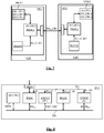
- the figure 7 shows electronic devices DV1, DV2 configured to implement a data processing method according to the invention.
- the devices DV1, DV2 are for example integrated circuits on semiconductor chips each arranged on a support CD1, CD2.
- the device DV1 forms, for example, a contact and / or contactless smart card, a non-contact electronic tag ("tag"), an SD or micro-SD card, or other electronic portable device.
- the device DV2 forms for example a smart card reader, a tag reader, an SD card reader, or any other type of terminal compatible with the device DV1.
- the devices DV1, DV1 each comprise a processor PROC1, PROC2, a memory MEM1, MEM2, a random generator RGEN1, RGEN2 and a communication interface circuit ICCT1, ICCT2 of wired, wireless ("wireless") or contactless type ( “contactless”).
- Each of the devices is equipped with cryptographic means, software or hardware (not shown), a shared cryptography key K and a shared PC generator polynomial, the key K and the polynomial PC being for example stored in their respective memories .
- a storage and transfer sequence is considered here during which the device DV1 stores a data item D in its memory MEM1 and then transfers it to the device DV2, which then stores it in its memory MEM2.
- the processor PROC1 generates or receives the data D, calculates its code CRC, then stores it in the memory MEM1 in its masked form D1 accompanied by the code CRC (step 27, Fig. 2 ).
- the mask R1 used for this purpose is supplied by the generator RGEN1 and is kept in a register of the processor.
- the processor PROC1 establishes a data link with the device DV2, via the circuits ICCT1, ICCT2. Then, the processor PROC1 reads the masked data D1 and the code CRC and executes the phase P4 (Cf. Fig. 4 ) to check the CRC code.
- the mask R2 used for this purpose is calculated by the processor PROC1 from a random number r2 provided by the generator RGEN1, or is directly supplied by the latter.
- the processor PROC1 executes a processing sequence protected against attacks, including the removal of the mask R1 and the transformation of the data D into a data D4 (K) encoded by means of the key K.
- the processor sends the data D4 (K) and the CRC code to the device DV2.
- the processor PROC2 decodes the data D by means of its own key K, the mask with a mask R2 'calculated from a random number r2' supplied by the generator RGEN2 or directly supplied by the latter, to obtain a data item D2 ' , checks its CRC code (steps 33, 34, Fig. 3 ), applies to it any mask R1 'to obtain a datum D3' (step 28, Fig. 2 ), stores the mask R1 'in a register, removes the mask R2' (step 29, Fig. 2 ) to obtain a data item D1 ', then stores the data item D1' in its memory MEM2 accompanied by the code CRC (step 27, Fig. 2 ).
- the masks R2, R2 ' are used both as storage masks and as calculation masks of the CRC code.
- the data D2, D2 'accompanied by the code CRC are then stored in the memories MEM1, MEM2, instead of the data D1, D1'.
- mask R2 is determined during a coupling phase of devices DV1, DV2 and is stored in their respective memories. The data is transmitted to the device DV2 in its masked form D2, the mask R2 is therefore also used here as a transfer mask.
- a data processing sequence in which the processor PROC must decode a message M received via the interface circuit ICCT is considered as an example.
- the encoded message M is of the type F K [D, CRC] and contains a data item D and its code CRC which have been concatenated and encoded together by means of a cryptography function F and the key K.
- the processor applies the message M on the data bus DB and requests the coprocessor CPROC to decode it.
- the latter loads the message M into an internal register (not shown), requests the generator RGEN to provide one or more masks Mi countermeasure, and a storage mask and transfer R1.
- the mask R1 is also supplied to the circuit CRCCT and to the coprocessor CPROC, which store it each in an internal register (not shown).
- the coprocessor decodes the message by means of the key K, to obtain the data D and its CRC code, masks the data D with the mask R1 to obtain the masked data D1, applies the data D1 on the data bus, request the RGEN generator to provide a random number r2 to the CRCCT circuit and request the CRCCT circuit to calculate its CRC code.
- the latter generates the mask R2, reads the data D1 on the bus, masks the data with R2 to obtain the masked data D3 (step 36, Fig. 4 ), removes the mask R1 to obtain the masked data D2 (step 37, Fig. 4 ), calculates a CRC 'code and applies it on the DB bus.
- the coprocessor compares the received CRC code with the data and CRC code calculated by the CRCCT circuit, and, if the two codes are identical, indicates to the processor PROC that the data has been correctly decoded.
- the processor takes the data D1 and the CRC code on the data bus, and executes one or more processing steps (Cf. Fig. 2 ).
- the mask R2 is used as a storage and transfer mask, instead of the mask R1.
- the mask R2 is no longer generated by the circuit CRCCT, but is provided by the generator RGEN instead of the mask R1.
- the generator RGEN is then equipped with a reception register of the polynomial PC and a multiplier. The steps of double masking, removing the mask R1 and removing the mask R2 executed by the circuit CRCCT are no longer necessary.
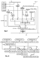
- the figure 9 represents an embodiment of the circuit CRCCT making it possible to implement the examples of data processing methods which have just been described.
- the circuit CRCCT comprises input registers REG1, REG2, REG3, buffer registers REG4, REG5, an output register REGS, a multiplier MLT, a polynomial adder AD1 (for example a series of exclusive OR gates with two inputs), a cyclic redundancy check code generating circuit CRCORE, and a multiplexing unit MUX. These different elements are controlled by a control unit CTU which receives CMD commands sent by the aforementioned processor or coprocessor.
- Example 3 relates to the first calculation of CRC code of the unmasked data D. It may however be desired to never apply the unmasked data D on the data bus.
- the processor may be configured to generate itself the masked data D1 or D2 from the mask R1 or the number r2 provided by the generator RGEN, as described above, and to provide the masked data D1 or D2 to the circuit CRCCT. This operation can, however, be performed in certain applications with insensitive data, or during a personalization step of the device performed in a secure location.
- the CRCCT circuit is susceptible to various other embodiments.
- a method of calculating CRC code according to the invention is also susceptible of various other variants.
- the CRC code can be calculated in successive passes from F fragments of the data D, for example when the input register REG1 of the circuit CRCCT is of insufficient size to receive the N bits of the data D.
- the figure 10 shows an example method for calculating the CRC code in successive passes from masked fragments of the data.
- the method comprises a generation step 1 ab or an acquisition step 2ab of a first random number r2ab, a generation step 1 bc or acquisition 2bc of a second random number r2bc, a generation step 1cd or a acquisition step 2cd of a third random number r2cd.
- Step 1ab or 2ab is followed by a step 3ab of generating a first mask fragment R2ab, by multiplying r2ab by PC.
- Step 1bc or 2bc is followed by a step 3bc of generating a second mask fragment R2bc, by multiplying r2bc by PC.
- Step 1cd or 2cd is followed by a step 3cd of generating a third mask fragment R2cd, by multiplying r2cd by PC.
- step 3ab can be replaced by a step 4ab of acquisition of the mask fragment R2ab
- step 3bc can be replaced by a step 4bc of acquisition of the fragment of mask R2bc
- step 3cd can be replaced by a step 4cd of acquisition of the mask fragment R2cd.
- the method then comprises a step 40 of fragmenting the data into three fragments Dab, Dc and Dd.
- the fragment Dab or fragment of greater weight, has a length (ie a number of bits) which is twice that of the other two fragments Dc, Dd. For example, if the data is 128 bits, the Dab fragment is 64 bits and the other two fragments are 32 bits.
- the fragment Dab is masked by means of the mask fragment R2ab, to obtain a masked data fragment D2ab.
- an intermediate cyclic redundancy check code CRCab is calculated from the masked data fragment D2ab and the polynomial PC.
- the fragment Dbc is masked by means of the mask fragment R2bc, to obtain a masked data fragment D2bc.
- an intermediate cyclic redundancy check code CRCbc is calculated from the fragment D2bc and PC.
- the fragment Dcd is masked by means of the mask fragment R2cd, to obtain a masked intermediate data fragment D2cd.
- a cyclic redundancy check code CRCcd is calculated from the masked intermediate data fragment D2cd and the polynomial PC. This code is both the CRC code of the intermediate fragment Dcd and the CRC code of the data D.
- the number of intermediate CRC codes calculated is equal to F-1.
- This method can be implemented by the circuit CRCCT of the figure 9 , adding the elements shown in dashed lines, namely an intermediate register REG6 having its input connected to the output of the CRCORE circuit, a CREG concatenation register having an input connected to the output of the register REG6 and an input connected to the output of the register REG1, and an output connected to an input E5 of the multiplexer.
- the register REG1 receives first the fragment Dab, the CRCORE circuit supplies the code CRCab which is transferred in REG6.
- the register REG1 receives the fragment Dc which is concatenated with CRCab in the register CREG, and the circuit CRCORE provides the code CRCbc which is transferred in REG6.
- the register REG1 receives the fragment Dd which is concatenated with CRCbc in CREG, and the CRCORE circuit then provides the desired CRC code.
- the register REG1 comprises several locations for storing fragments Dab, Dc and Dd.
- the random numbers r2ab, r2bc and r2cd are identical.
- the numbers r2ab, r2bc and r2cd are provided to the circuit CRCCT as the calculation progresses.
- the register REG3 comprises several locations for simultaneously storing the numbers r2ab, r2bc and r2cd, or even others, up to a value r2n. In this case, during an unfragmented CRC calculation, several numbers r2 may be randomly selected by the CTU.
- a random generator is integrated in the CRCCT circuit.
- a data processing method according to the invention can in particular be implemented by means of various generator polynomials other than CRC-16-DECT, for example the known generator polynomials CRC-1, CRC-4-ITU, CRC-5- EPC, CRC-5-ITU, CRC-5-USB, CRC-6-ITU, CRC-7, CRC-8-CCITT, CRC-8-Dallas / Maxim, CRC-8, CRC-8-SAE J1850, CRC -8-WCDMA, CRC-10, CRC-11, CRC-12, CRC-15-CAN, CRC-16-IBM, CRC-16-CCITT, CRC-16-T10-DIF, CRC-16-DNP, CRC ARINC, CRC-16-Fletcher, CRC-24, CRC-24-Radix-64 CRC-30, CRC-32-Adler, CRC-32, CRC-32C (
- the term “random” may mean “pseudo-random”. Also, the term “random” may simply mean “that is not known to an attacker", the mask R1 or R2 may be generated from a known seed and a deterministic function, as previously indicated.
Description
La présente invention concerne un procédé de traitement d'une donnée binaire, comprenant une étape de calcul d'un code de contrôle de redondance cyclique au moyen d'un polynôme générateur. La présente invention concerne également la protection des circuits intégrés à semi-conducteur contre des attaques par canaux auxiliaires.The present invention relates to a method for processing a binary data, comprising a step of calculating a cyclic redundancy check code by means of a generator polynomial. The present invention also relates to the protection of semiconductor integrated circuits against attacks by auxiliary channels.
Les circuits intégrés sur puce de semi-conducteur utilisés dans des applications sécurisées font l'objet de diverses attaques, notamment des attaques par canaux auxiliaires basées sur l'observation de leur consommation de courant, leur rayonnement magnétique ou électromagnétique. De telles attaques visent à découvrir les données sensibles qu'ils manipulent, par exemple des clés de cryptographie, des données d'application, des variables intermédiaires de calcul...Semiconductor chip ICs used in secure applications are subject to various attacks, including aux-channel attacks based on observation of their current consumption, magnetic or electromagnetic radiation. Such attacks are aimed at discovering the sensitive data they handle, for example cryptography keys, application data, intermediate calculation variables, etc.
Les attaques par canaux auxiliaires les plus répandues mettent en oeuvre des méthodes d'analyse statistique telle que l'analyse DPA ("Differential Power Analysis") ou CPA ("Correlation Power Analysis"). Ces techniques d'analyse permettent de retrouver la clé d'un algorithme de cryptographie grâce à l'acquisition de nombreuses courbes de consommation du circuit. L'analyse DPA consiste dans un classement statistique de courbes de consommation de courant en fonction d'une hypothèse sur la clé recherchée. L'analyse CPA se base sur un modèle de consommation de courant et consiste à calculer un coefficient de corrélation entre, d'une part, les points de consommation mesurée et, d'autre part, une valeur estimée de consommation, calculée à partir du modèle de consommation et d'une hypothèse sur l'opération qu'exécute le circuit.The most common auxiliary channel attacks use statistical analysis methods such as DPA ("Differential Power Analysis") or CPA ("Correlation Power Analysis") analysis. These analysis techniques make it possible to find the key of a cryptographic algorithm by acquiring numerous curves of consumption of the circuit. The DPA analysis consists in a statistical classification of current consumption curves according to a hypothesis on the key sought. The CPA analysis is based on a current consumption model and consists in calculating a correlation coefficient between, on the one hand, the measured consumption points and, on the other hand, an estimated consumption value, calculated from the model of consumption and a hypothesis on the operation that the circuit performs.
Diverses contre-mesures matérielles et/ou logicielles sont généralement mises en oeuvre pour contrer de telles attaques. Notamment, les données sensibles sont généralement stockées ou transférées sous forme masquée, c'est-à-dire après avoir été combinées avec un masque binaire supposé inconnu d'un attaquant, et ne sont généralement démasquées que lorsqu'elles se trouvent dans une zone entièrement protégée contre les attaques.Various hardware and / or software countermeasures are generally implemented to counter such attacks. In particular, the sensitive data is generally stored or transferred in masked form, that is to say after having been combined with a binary mask assumed to be unknown by an attacker, and are generally unmasked only when they are in an area fully protected from attack.
D'autre part, les données manipulées par les circuits intégrés sont généralement protégées contre une corruption de données pouvant être accidentelle ou résulter d'un acte volontaire. Une corruption de données peut par exemple se produire lors d'une altération de la tension de seuil de cellules mémoires dans lesquelles les données sont stockées, d'une interférence électromagnétique pendant que des données sont véhiculées sur un bus de données, ou lors d'une attaque par injection de faute. Les données, pendant leur stockage ou leur transfert, sont donc accompagnées d'un code de détection d'erreur appelé "somme de contrôle" ("checksum"). Il peut s'agir par exemple d'un bit de parité, d'un code de Hamming, d'un code CRC ou code de contrôle de redondance cyclique ("cyclic redundancy check"), etc.On the other hand, data handled by integrated circuits is generally protected against data corruption that may be accidental or result from a voluntary act. For example, data corruption may occur when the threshold voltage of memory cells in which the data is stored is altered, electromagnetic interference occurs while data is being carried on a data bus, or when an attack by fault injection. The data, during storage or transfer, are therefore accompanied by an error detection code called "checksum". It can be for example a parity bit, a Hamming code, a CRC code or cyclic redundancy check code, etc.
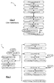
La
- une
étape 10 d'acquisition de la donnée D, - une
étape 11 de calcul du code CRC de la donnée D au moyen d'un polynôme générateur PC, - une
étape 12 de masquage de la donnée avec un masque R1, par addition de celle-ci avec le masque R1, pour obtenir une donnée masquée D1, et - une
étape 13 de traitement de la donnée D.
- a
step 10 of acquiring the data D, - a
step 11 of calculating the CRC code of the data D by means of a PC generator polynomial, - a
step 12 of masking the data with a mask R1, by adding it with the mask R1, to obtain a masked data D1, and - a
step 13 of processing the data D.
A l'étape 11, le code CRC est calculé par division polynomiale de la donnée par le polynôme PC, effectuée dans GF(2)[X], soit le corps des polynômes dont les coefficients appartiennent au corps fini GF(2) (corps de Galois), qui forme le plus petit corps fini connu. L'addition exécutée à l'étape 12 est l'addition polynomiale dans GF(2)[X] correspondant en algèbre booléenne au OU Exclusif bit à bit du masque R1 et de la donnée D. Enfin, l'étape de traitement 13 peut consister dans le stockage de la donnée dans une mémoire ou sa transmission à une entité autre que celle qui a exécuté les étapes 10 à 12. La donnée est dans ce cas stockée ou transmise sous sa forme masquée D1 et est accompagnée du code CRC.In
La phase de traitement ultérieure comprend :
- une
étape 14 d'acquisition de la donnée masquée D1 et de son code CRC (réception ou lecture dans une mémoire), - une
étape 15 de démasquage de la donnée D, c'est-à-dire de retrait du masque R1, en additionnant la donnée masquée D1 avec le masque R1, - une
étape 16 de calcul d'un code CRC' de la donnée D, au moyen du polynôme PC, - une
étape 17 de comparaison des codes CRC et CRC', - si les codes CRC et CRC' sont différents, une
étape 18 de traitement d'erreur, et - si les codes CRC et CRC' sont identiques, une
étape 19 de traitement de la donnée D.
- a
step 14 of acquisition of the masked data D1 and its CRC code (reception or reading in a memory), - a
step 15 of unmasking the data D, that is to say removing the mask R1, adding the masked data D1 with the mask R1, - a
step 16 of calculating a code CRC 'of the data D, by means of the polynomial PC, - a
step 17 of comparing the CRC and CRC 'codes, - if the CRC and CRC 'codes are different, an
error processing step 18, and - if CRC and CRC 'are identical, a
step 19 of processing data D.
Des modes de réalisation de l'invention se fondent sur la découverte d'une faille de sécurité dans ce procédé de traitement de données. Cette faille de sécurité concerne l'étape 11 ou 16 de calcul du code CRC, effectuée à partir de la donnée démasquée, sans quoi le code CRC serait erroné. Or, on a découvert que cette étape de calcul est susceptible de certains types d'attaques pouvant permettre de découvrir la valeur de la donnée D. En particulier, une attaque de type "template" (attaque au moyen d'un modèle) est envisageable. L'attaque consiste à former une base de données de tous les profils de consommation électrique du circuit réalisant le calcul du code CRC en fonction de la valeur de la donnée D. L'observation du profil de consommation du circuit pendant le calcul du code CRC permet ensuite de retrouver, dans la base de données, la valeur correspondante de la donnée D. Une attaque de type DPA pendant le calcul du code CRC pourrait également, dans certaines applications, être envisageable.Embodiments of the invention are based on the discovery of a security breach in this data processing method. This security flaw concerns the
Il pourrait être donc souhaité d'améliorer la sécurité offerte par un procédé de traitement de données incluant un calcul de code CRC.It may therefore be desirable to improve the security offered by a data processing method including a CRC code calculation.
Le document
Des modes de réalisation de l'invention concernent un procédé de traitement d'une donnée binaire, comprenant une étape de calcul d'un code de contrôle de redondance cyclique de la donnée au moyen d'un polynôme générateur, dans lequel l'étape de calcul du code de contrôle de redondance cyclique comprend les étapes consistant à masquer la donnée avec un masque binaire aléatoire qui est un multiple du polynôme générateur, par addition polynomiale de la donnée et du masque, et générer le code de contrôle de redondance cyclique de la donnée à partir de la donnée masquée.Embodiments of the invention relate to a method of processing a binary data, comprising a step of calculating a cyclic redundancy check code of the data by means of a generator polynomial, wherein the step of computation of the cyclic redundancy check code comprises the steps of masking the data with a random bit mask which is a multiple of the generator polynomial, by polynomial addition of the data and the mask, and generating the cyclic redundancy check code of the given from the hidden data.
Selon un mode de réalisation, le procédé comprend les étapes consistant à fragmenter la donnée en au moins deux parties, masquer une première partie de la donnée avec un premier masque binaire aléatoire qui est un multiple du polynôme générateur, et générer un premier code de contrôle de redondance cyclique de la première partie masquée, concaténer le premier code de contrôle de redondance cyclique avec une partie suivante de la donnée, pour former une donnée intermédiaire, masquer la donnée intermédiaire avec un second masque binaire aléatoire qui est un multiple du polynôme générateur, et générer un second code de contrôle de redondance cyclique de la donnée intermédiaire masquée.According to one embodiment, the method comprises the steps of fragmenting the data into at least two parts, masking a first portion of the data with a first random bit mask that is a multiple of the generator polynomial, and generating a first control code cyclic redundancy of the first masked portion, concatenating the first cyclic redundancy check code with a subsequent portion of the data, to form an intermediate data, masking the intermediate data with a second random bit mask which is a multiple of the generator polynomial, and generating a second cyclic redundancy check code of the masked intermediate data.
Selon un mode de réalisation, le procédé comprend une étape de génération du masque binaire aléatoire comprenant les étapes consistant à générer un nombre aléatoire quelconque, et multiplier le nombre aléatoire quelconque par le polynôme générateur.According to one embodiment, the method comprises a step of generating the random bit mask comprising the steps of generating any random number, and multiplying any random number by the generator polynomial.
Selon un mode de réalisation, la donnée comprend N bits et le polynôme générateur P bits, et le nombre aléatoire quelconque généré comprend au moins N - P bits.According to one embodiment, the data comprises N bits and the generator polynomial P bits, and any random number generated comprises at least N - P bits.
Selon un mode de réalisation, le procédé comprend une étape de génération du masque binaire aléatoire comprenant les étapes consistant à générer un premier nombre aléatoire quelconque, multiplier le premier nombre aléatoire quelconque par le polynôme générateur pour obtenir une première partie de masque, générer au moins un second nombre aléatoire quelconque, multiplier le second nombre aléatoire quelconque par le polynôme générateur pour obtenir au moins une second partie de masque, et concaténer les première et seconde parties de masque.According to one embodiment, the method comprises a step of generating the random bit mask comprising the steps of generating a first random number, multiplying the first random number by the generator polynomial to obtain a first mask part, generating at least one second arbitrary random number, multiplying the second arbitrary random number by the generator polynomial to obtain at least a second mask portion, and concatenating the first and second mask portions.
Selon un mode de réalisation, la donnée comprend N bits et le polynôme générateur P bits, et chaque nombre aléatoire quelconque généré comprend un nombre de bits égal à (N-nP)/n, n étant le nombre de nombres aléatoires quelconques générés.According to one embodiment, the data comprises N bits and the generator polynomial P bits, and each random number generated generates a number of bits equal to (N-nP) / n, where n is the number of random numbers generated.
Selon un mode de réalisation, le procédé comprend les étapes consistant à acquérir la donnée sous une forme masquée avec un premier masque binaire aléatoire quelconque formant un masque de stockage ou de transfert, accompagnée d'un premier code de contrôle de redondance cyclique, retirer le premier masque de la donnée, masquer la donnée avec un second masque binaire aléatoire qui est un multiple du polynôme générateur, générer un second code de contrôle de redondance cyclique à partir de la donnée masquée avec le second masque, et comparer le premier et le second codes de contrôle de redondance cyclique.According to one embodiment, the method comprises the steps of acquiring the data in masked form with any first random bit mask forming a storage or transfer mask, accompanied by a first cyclic redundancy check code, removing the first mask of the data, mask the data with a second random binary mask which is a multiple of the generator polynomial, generate a second cyclic redundancy check code from the masked data with the second mask, and compare the first and the second cyclic redundancy check codes.
Selon un mode de réalisation, le procédé comprend les étapes consistant à acquérir la donnée sous une forme masquée par un premier masque binaire aléatoire quelconque formant un masque de stockage ou de transfert, accompagnée d'un premier code de contrôle de redondance cyclique, masquer une seconde fois la donnée avec un second masque binaire aléatoire qui est un multiple du polynôme générateur, retirer le premier masque à la donnée masquée deux fois, générer un second code de contrôle de redondance cyclique à partir de la donnée masquée avec le second masque, et comparer le premier et le second codes de contrôle de redondance cyclique.According to one embodiment, the method comprises the steps of acquiring the data in a masked form by a first arbitrary random bit mask forming a storage or transfer mask, accompanied by a first cyclic redundancy check code, masking a second time the data with a second random bit mask which is a multiple of the generator polynomial, removing the first mask with the masked data twice, generating a second cyclic redundancy check code from the masked data with the second mask, and compare the first and the second cyclic redundancy check codes.
Selon un mode de réalisation, le procédé comprend les étapes consistant à acquérir la donnée sous une forme masquée avec un premier masque binaire qui est un multiple du polynôme générateur, formant un masque de stockage ou de transfert, générer un second code de contrôle de redondance cyclique à partir de la donnée masquée avec le premier masque, et comparer le premier et le second codes de contrôle de redondance cyclique.According to one embodiment, the method comprises the steps of acquiring the data in a masked form with a first bit mask that is a multiple of the generator polynomial, forming a storage or transfer mask, generating a second cyclic redundancy check code from the masked data with the first mask, and comparing the first and second cyclic redundancy check codes.
Des modes de réalisation de l'invention concernent également un dispositif électronique comprenant des moyens de traitement d'une donnée, configuré pour mettre en oeuvre des étapes de traitement du procédé décrit ci-dessus.Embodiments of the invention also relate to an electronic device comprising data processing means, configured to implement processing steps of the method described above.
Des modes de réalisation de l'invention concernent également un objet portatif comprenant un tel dispositif électronique.Embodiments of the invention also relate to a portable object comprising such an electronic device.
Des modes de réalisation de l'invention concernent également un procédé de stockage ou de transfert d'une donnée accompagnée d'un code de contrôle de redondance cyclique de la donnée calculé au moyen d'un polynôme générateur (PC), comprenant une étape préalable de masquage de la donnée avec un masque binaire aléatoire par addition polynomiale de la donnée et du masque, dans lequel la donnée est stockée ou transférée sous une forme masquée avec un masque binaire aléatoire qui est un multiple dudit polynôme générateur.Embodiments of the invention also relate to a method for storing or transferring data accompanied by a cyclic redundancy check code of the data item calculated by means of a generator polynomial (PC), comprising a prior step masking the data with a random bit mask by polynomial addition of the data and the mask, wherein the data is stored or transferred in masked form with a random bit mask which is a multiple of said generator polynomial.
Selon un mode de réalisation, le procédé comprend une étape de génération du masque binaire aléatoire comprenant les étapes consistant à générer un nombre aléatoire quelconque, et multiplier le nombre aléatoire quelconque par le polynôme générateur.According to one embodiment, the method comprises a step of generating the random bit mask comprising the steps of generating any random number, and multiplying any random number by the generator polynomial.
Selon un mode de réalisation, le procédé comprend une étape de génération du masque binaire aléatoire comprenant les étapes consistant à générer un premier nombre aléatoire quelconque, multiplier le premier nombre aléatoire quelconque par le polynôme générateur pour obtenir une première partie de masque, générer au moins un second nombre aléatoire quelconque, multiplier le second nombre aléatoire quelconque par le polynôme générateur pour obtenir au moins une seconde partie de masque, et concaténer les première et seconde parties de masque.According to one embodiment, the method comprises a step of generating the random bit mask comprising the steps of generating a first random number, multiplying the first random number by the generator polynomial to obtain a first mask part, generating at least any second random number, multiply the second arbitrary random number by the generator polynomial to obtain at least one second mask part, and concatenating the first and second mask parts.
Des modes de réalisation de l'invention concernent également un dispositif électronique comprenant des moyens de stockage et de transfert d'une donnée, configuré pour stocker ou transférer la donnée conformément au procédé de stockage ou de transfert décrit ci-dessus.Embodiments of the invention also relate to an electronic device comprising means for storing and transferring data, configured to store or transfer the data in accordance with the storage or transfer method described above.
Des modes de réalisation de procédés et de circuits de traitement de données selon l'invention seront décrits plus en détail dans la description qui suit, en se référant à titre non limitatif aux figures jointes parmi lesquelles :
- la
figure 1 précédemment décrite montre des étapes d'un procédé de traitement de données classique, - la
figure 2 montre des étapes d'une première phase d'un procédé de traitement de données selon l'invention, - la
figure 3 montre des étapes d'une seconde phase du procédé de traitement de données selon l'invention, - la
figure 4 montre une variante de réalisation de la seconde phase du procédé, - la
figure 5 montre une autre variante de réalisation de la seconde phase du procédé, - la
figure 6 montre une première variante de certaines étapes du procédé de traitement de données selon l'invention, - la
figure 7 montre des dispositifs de traitement de données selon l'invention, - la
figure 8 montre un autre exemple de dispositif de traitement de données selon l'invention, - la
figure 9 montre un exemple de réalisation d'un circuit de calcul de code CRC selon l'invention, et - la
figure 10 montre une seconde variante de certaines étapes du procédé de traitement de données selon l'invention.
- the
figure 1 previously described shows steps of a conventional data processing method, - the
figure 2 shows steps of a first phase of a data processing method according to the invention, - the
figure 3 shows steps of a second phase of the data processing method according to the invention, - the
figure 4 shows an alternative embodiment of the second phase of the process, - the
figure 5 shows another variant embodiment of the second phase of the process, - the
figure 6 shows a first variant of certain steps of the data processing method according to the invention, - the
figure 7 shows data processing devices according to the invention, - the
figure 8 shows another example of a data processing device according to the invention, - the
figure 9 shows an exemplary embodiment of a CRC code calculation circuit according to the invention, and - the
figure 10 shows a second variant of certain steps of the data processing method according to the invention.
Des modes de réalisation de la présente invention se fondent sur la découverte que le code CRC d'une donnée peut être généré valablement à partir d'une donnée masquée, à condition que la donnée soit masquée au moyen d'un masque qui est un multiple du polynôme générateur du code CRC. Un masque aléatoire ayant cette propriété peut être généré à partir d'un nombre aléatoire, en multipliant le nombre aléatoire par le polynôme générateur. Considérons à titre d'exemple numérique le cas suivant :
- 1) soit une donnée D quelconque de 32 bits, par exemple D = a120b721h, ("h" représentant l'écriture de la donnée en base 16). La donnée peut aussi s'écrire comme un polynôme de degré 31 :

- 2) soit un polynôme générateur PC de degré 16, par exemple le polynôme connu CRC-16-DECT :

Il est à noter qu'un calcul conventionnel du code CRC de la donnée D, par division de celle-ci par le polynôme PC dans le corps fini GF(2)[X], donne un polynôme de degré 15, soit ici :
- 3) au lieu de calculer le code CRC à partir de la donnée D, considérons un nombre aléatoire quelconque r2 de 15 bits, par exemple :


- 4) multiplions r2 par le polynôme générateur, pour obtenir un
masque R2 de 32 bits :
- 5) masquons la donnée D avec le masque R2 (addition polynomiale dans GF(2)[X], correspondant à une opération OU Exclusif bit à bit), pour obtenir une donnée masquée D2, soit ici :

- 6) pour calculer le code CRC de la donnée D, effectuons la division polynomiale de la donnée masquée D2 par le polynôme PC dans GF(2)[X], soit la division polynomiale modulo 2. On obtient :

- 1) is any 32-bit D datum, for example D = a120b721 h , ("h" representing the writing of the data base 16). The data can also be written as a polynomial of degree 31:
- 2) either a PC generator polynomial of
degree 16, for example the known polynomial CRC-16-DECT:
It should be noted that a conventional computation of the CRC code of the data D, by division of this one by the polynomial PC in the finite field GF (2) [X], gives a polynomial ofdegree 15, here: - 3) instead of calculating the CRC code from the data D, consider any random number r2 of 15 bits, for example:
- 4) multiply r2 by the generator polynomial, to obtain a
mask 32 of 32 bits: - 5) mask the data D with the mask R2 (polynomial addition in GF (2) [X], corresponding to a bitwise OR operation OR), to obtain a masked data D2, here:
- 6) to compute the CRC code of the data D, perform the polynomial division of the masked data D2 by the polynomial PC in GF (2) [X], ie the polynomial division modulo 2. We obtain:
Il apparaît donc que le code CRC calculé à partir de la donnée masquée D2 est identique au code CRC calculé à partir de la donnée non masquée D. Il peut être démontré que cette règle est valable pour tout masque R2 multiple de PC.It therefore appears that the CRC code calculated from the masked data D2 is identical to the CRC code calculated from the non-masked data D. It can be shown that this rule is valid for any mask R2 multiple of PC.
Dans un mode de réalisation préféré, le masque R2 a la même longueur que la donnée D à masquer, afin de masquer tous les bits de la donnée. Dans ce cas, la règle suivante est observée : si la donnée D comprend N bits et le polynôme PC comprend P bits, alors le nombre aléatoire quelconque r2 comprend Q bits avec Q égal à N-P bits. Dans l'exemple ci-dessus N=32, P=17, Q=15. Par ailleurs, le code CRC obtenu présente P-1 bits, soit ici 16 bits.In a preferred embodiment, the mask R2 has the same length as the data D to be masked, in order to mask all the bits of the data. In this case, the following rule is observed: if the data D comprises N bits and the polynomial PC comprises P bits, then any random number r2 comprises Q bits with Q equal to N-P bits. In the above example N = 32, P = 17, Q = 15. In addition, the CRC code obtained has P-1 bits, ie here 16 bits.
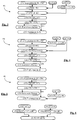
La
une étape 1 de génération du nombre aléatoire r2,une étape 3 de génération du masque aléatoire R2 par multiplication de r2 par PC,une étape 20 d'acquisition de la donnée D,une étape 21 de masquage de la donnée avec le masque R2, en additionnant celle-ci au masque R2, pour obtenir la donnée masquée D2, etune étape 22 de calcul du code CRC de la donnée D à partir du polynôme PC et de la donnée masquée D2, de sorte que l'étape de calcul est protégée notamment contre une attaque de type "template", etune étape 23 de traitement de la donnée.
- a
step 1 of generating the random number r2, - a
step 3 of generating the random mask R2 by multiplying r2 by PC, - a
step 20 of acquiring data D, - a
step 21 of masking the data with the mask R2, adding it to the mask R2, to obtain the masked data D2, and - a
step 22 of calculating the CRC code of the data D from the polynomial PC and the masked data item D2, so that the calculation step is protected in particular against a "template" type attack, and - a
step 23 of processing the data.
Divers exemples de réalisation de l'étape de traitement 23 sont montrés sur la
- Exemple 1 : l'étape de traitement 23 comprend une étape 24 de retrait du masque R2, par addition polynomiale dans GF(2)[X] de la donnée masquée D2 avec le masque R2, suivie d'une étape 25 de manipulation de la donnée non masquée D. Ces étapes sont de préférence réalisées par un circuit ou une partie de circuit protégée contre des attaques.
L'étape d'utilisation 25 comprend par exemple l'exécution d'un calcul cryptographique, la donnée étant un message à encoder, une clé ou une sous-clé utilisée pour encoder un message. - Exemple 2 : l'étape de traitement 23
comprend l'étape 24 de retrait du masque R2, suivie d'une étape 26 de masquage de la donnée démasquée D avec un masque aléatoire quelconque R1, c'est-à-dire qui n'est pas nécessairement un multiple de PC, pour obtenir une donnée masquée D1. Au cours d'une étape 27, la donnée masquée D1 est stockée dans une mémoire ou transférée à un autre organe ou entité que celui ou celle qui a conduit les étapes précitées, accompagnée de son code CRC. - Exemple 3 : l'étape de traitement 23 comprend une étape 28 de masquage de la donnée masquée D2 avec le masque aléatoire quelconque R1, pour obtenir une donnée D3 masquée deux fois.
L'étape 28 est suivie d'une étape 29 de retrait du masque R2, par addition du masque à la donnée D3, et conduit au même résultat que l'étape 26 précitée, à savoir la donnée D1 masquée par le masque R1.L'étape 29 est suivie de l'étape 27 précitée. - Exemple 4 : dans cet exemple, la donnée masquée D2 est simplement stockée dans une mémoire ou transférée à un autre organe ou entité que celui ou celle qui a conduit les étapes précitées, accompagnée de son code CRC (étape 30).
- Example 1: the
treatment step 23 comprises astep 24 of removing the mask R2, by polynomial addition in GF (2) [X] of the masked data D2 with the mask R2, followed by astep 25 of handling the data not masked D. These steps are preferably performed by a circuit or part of circuit protected against attacks. Theuse step 25 comprises for example the execution of a cryptographic calculation, the data being a message to be encoded, a key or a subkey used to encode a message. - Example 2: the processing
step 23 includes thestep 24 of removing the mask R2, followed by astep 26 of masking the unmasked data D with any random mask R1, that is to say, which n ' is not necessarily a multiple of PC, to obtain a masked data D1. During astep 27, the masked data D1 is stored in a memory or transferred to another body or entity than the one who conducted the above steps, accompanied by its CRC code. - Example 3: the processing
step 23 comprises astep 28 of masking the masked data D2 with the random mask R1, to obtain a datum D3 masked twice.Step 28 is followed by astep 29 of removing mask R2, by adding the mask to data D3, and leads to the same result asstep 26 above, namely data D1 masked by mask R1.Step 29 is followed bystep 27 above. - Example 4: In this example, the masked data D2 is simply stored in a memory or transferred to another body or entity than the one who conducted the above steps, accompanied by its CRC code (step 30).
Il sera noté que l'étape de masquage 26 de l'exemple 2 ou l'étape de masquage 28 de l'exemple 3 est précédée d'une étape 6 de génération du masque R1 ou d'une étape 7 d'acquisition du masque R1.It will be noted that the masking
Il sera également noté que l'exemple 3 est une variante préférée de l'exemple 2, qui présente l'inconvénient de laisser la donnée en clair entre l'étape 24 et l'étape 26, ce qui peut ne pas être souhaitable si le retrait du masque est réalisé en environnement non sécurisé.It will also be noted that Example 3 is a preferred variant of Example 2, which has the disadvantage of leaving the data in clear between
Enfin, l'étape de traitement 23 peut comporter une combinaison différente des diverses étapes 24 à 30 qui viennent d'être décrites.Finally, the
La phase initiale de traitement P2 peut être suivie de phases de traitement ultérieures P3, P4, P5, montrées sur les
La phase P3,
L'étape de traitement d'erreur 35 peut comprendre diverses actions en fonction de la nature de l'opération en cours d'exécution, de l'émission d'un simple signal d'erreur à l'exécution d'actions sécuritaires, comme l'interruption de l'opération en cours d'exécution voire la destruction de données sensibles ou la remise à zéro du circuit réalisant cette opération.The
L'étape de démasquage 32 est précédée de l'étape 6 de génération du masque R1 ou de l'étape 7 d'acquisition du masque R1. Le masque R1 ayant été déjà généré, l'étape 6 n'est possible que si cette génération est répétable, par exemple au moyen d'une graine aléatoire connue et d'une fonction de génération déterministe. Dans le cas contraire, l'étape d'acquisition 7 doit être prévue. Elle consiste par exemple à lire le masque dans un registre ou dans une mémoire, à une adresse prédéterminée ou reçue par l'intermédiaire d'une commande.The unmasking
L'étape de masquage 21 est précédée de l'étape 3 de génération du masque R2 et inclut la multiplication de r2 par le polynôme PC, ou d'une étape 4 d'acquisition du masque R2. L'étape 3, le cas échéant, est précédée de l'étape 1 de génération d'un nombre r2 aléatoire ou d'une étape 2 d'acquisition du nombre r2. Il n'est pas nécessaire ici, pour le masquage pendant l'étape de calcul 33, que le nombre r2 généré à l'étape 1 soit identique à celui généré à l'étape 1 de la
La phase P4,
L'étape de masquage 36 est précédée de l'étape 3 de génération du masque R2 ou de l'étape 4 d'acquisition du masque R2. Le cas échéant, l'étape 3 est précédée de l'étape 1 de génération aléatoire du nombre r2 ou de l'étape 2 d'acquisition du nombre r2. Également, l'étape de démasquage 37 est précédée de l'étape 6 de génération du masque R1 ou de l'étape 7 d'acquisition du masque R1.The masking
La phase P5,
L'étape de traitement 23 peut nécessiter préalablement l'exécution de l'étape 3 de génération du masque R2 ou de l'étape 4 d'acquisition du masque R2, par exemple si elle inclut les étapes 24 et 25 (
La
Le masque peut aussi être généré avec un plus grand nombre de fragments r2i. De façon générale, si la donnée comprend N bits et le polynôme générateur P bits, les fragments r2i présentent chacun un nombre de bits égal à (N-nP)/n, n représentant le nombre de fragments r2i générés.The mask can also be generated with a larger number of r2i fragments. In general, if the data comprises N bits and the generator polynomial P bits, the fragments r2i each have a number of bits equal to (N-nP) / n, where n represents the number of generated r2i fragments.
La
Les dispositifs DV1, DV1 comprennent chacun un processeur PROC1, PROC2, une mémoire MEM1, MEM2, un générateur aléatoire RGEN1, RGEN2 et un circuit d'interface de communication ICCT1, ICCT2 de type filaire, sans fil ("wireless") ou sans contact ("contactless"). Chacun des dispositifs est équipé de moyens de cryptographie, logiciels ou matériels (non représentés), d'une clé de cryptographie partagée K et d'un polynôme générateur PC partagé, la clé K et le polynôme PC étant par exemple stockés dans leur mémoires respectives.The devices DV1, DV1 each comprise a processor PROC1, PROC2, a memory MEM1, MEM2, a random generator RGEN1, RGEN2 and a communication interface circuit ICCT1, ICCT2 of wired, wireless ("wireless") or contactless type ( "contactless"). Each of the devices is equipped with cryptographic means, software or hardware (not shown), a shared cryptography key K and a shared PC generator polynomial, the key K and the polynomial PC being for example stored in their respective memories .
On considère ici, à titre d'exemple de fonctionnement, une séquence de stockage et de transfert au cours de laquelle le dispositif DV1 stocke une donnée D dans sa mémoire MEM1 puis la transfère au dispositif DV2, qui la stocke ensuite dans sa mémoire MEM2. Au cours d'une phase initiale de traitement correspondant à la phase P2 précitée (
Dans une variante de réalisation, les masques R2, R2' sont utilisés à la fois comme masques de stockage et comme masques de calcul du code CRC. Les données D2, D2' accompagnées du code CRC sont alors stockées dans les mémoires MEM1, MEM2, à la place des données D1, D1'.In an alternative embodiment, the masks R2, R2 'are used both as storage masks and as calculation masks of the CRC code. The data D2, D2 'accompanied by the code CRC are then stored in the memories MEM1, MEM2, instead of the data D1, D1'.
Dans une autre variante ne faisant pas intervenir un procédé de cryptographie pour transférer la donnée D, le masque R2 est déterminé au cours d'une phase de couplage des dispositifs DV1, DV2 et est conservé dans leurs mémoires respectives. La donnée est transmise au dispositif DV2 sous sa forme masquée D2, le masque R2 étant donc également utilisé ici comme masque de transfert.In another variant that does not involve a cryptographic method for transferring data D, mask R2 is determined during a coupling phase of devices DV1, DV2 and is stored in their respective memories. The data is transmitted to the device DV2 in its masked form D2, the mask R2 is therefore also used here as a transfer mask.
La
- de fournir au coprocesseur CPROC des masques aléatoires Mi permettant de mettre en oeuvre des contre-mesures (par exemple contre des attaques de type DPA)
- de fournir au circuit CRCCT, au processeur PROC, et au coprocesseur CPROC un masque aléatoire quelconque R1 pour le stockage ou le transfert de données,
- de fournir au circuit CRCCT le nombre aléatoire quelconque r2, ce dernier étant configuré ici pour fournir le masque aléatoire R2 multiple d'un polynôme PC, à partir du nombre r2.
- to provide the coprocessor CPROC random masks Mi to implement countermeasures (for example against attacks DPA type)
- supplying to the circuit CRCCT, the processor PROC, and the coprocessor CPROC any random mask R1 for storing or transferring data,
- to provide the circuit CRCCT any random number r2, the latter being configured here to provide the random mask R2 multiple of a polynomial PC, from the number r2.
On considère à titre d'exemple une séquence de traitement de données au cours de laquelle le processeur PROC doit décoder un message M reçu via le circuit d'interface ICCT. Le message encodé M est du type FK [D, CRC] et renferme une donnée D et son code CRC qui ont été concaténées et encodées ensemble au moyen d'une fonction de cryptographie F et de la clé K.By way of example, a data processing sequence in which the processor PROC must decode a message M received via the interface circuit ICCT is considered as an example. The encoded message M is of the type F K [D, CRC] and contains a data item D and its code CRC which have been concatenated and encoded together by means of a cryptography function F and the key K.
Le processeur applique le message M sur le bus de données DB et demande au coprocesseur CPROC de le décoder. Ce dernier charge le message M dans un registre interne (non représenté), demande au générateur RGEN de lui fournir un ou plusieurs masques Mi de contre-mesure, ainsi qu'un masque de stockage et de transfert R1. Le masque R1 est également fourni au circuit CRCCT et au coprocesseur CPROC, qui le mémorisent chacun dans un registre interne (non représenté). Au cours d'une séquence protégée contre des attaques, le coprocesseur décode le message au moyen de la clé K, pour obtenir la donnée D et son code CRC, masque la donnée D avec le masque R1 pour obtenir la donnée masquée D1, applique la donnée D1 sur le bus de données, demande au générateur RGEN de fournir un nombre aléatoire r2 au circuit CRCCT et demande au circuit CRCCT de calculer son code CRC. Ce dernier génère le masque R2, lit la donnée D1 sur le bus, masque la donnée avec R2 pour obtenir la donnée masquée D3 (étape 36,
Dans une variante, le masque R2 est utilisé comme masque de stockage et de transfert, à la place du masque R1. Dans ce cas, le masque R2 n'est plus généré par le circuit CRCCT, mais est fourni par le générateur RGEN à la place du masque R1. Le générateur RGEN est alors équipé d'un registre de réception du polynôme PC et d'un multiplieur. Les étapes de double masquage, de retrait du masque R1 et de retrait du masque R2 exécutées par le circuit CRCCT ne sont plus nécessaires.In a variant, the mask R2 is used as a storage and transfer mask, instead of the mask R1. In this case, the mask R2 is no longer generated by the circuit CRCCT, but is provided by the generator RGEN instead of the mask R1. The generator RGEN is then equipped with a reception register of the polynomial PC and a multiplier. The steps of double masking, removing the mask R1 and removing the mask R2 executed by the circuit CRCCT are no longer necessary.
La
Le registre REG1 comprend une entrée reliée au bus de données DB et est prévu pour recevoir séquentiellement le polynôme PC et une donnée dont le code CRC doit être calculé, par exemple la donnée D, la donnée masquée D1 ou la donnée masquée D2. La sortie du registre REG1 est reliée à une entrée du registre REG4, prévu pour recevoir le polynôme PC, et à une entrée E1 du multiplexeur MUX. La sortie du registre REG4 est reliée à une première entrée du multiplieur MLT et à une entrée E1 du circuit CRCORE. Le registre REG2 a une entrée reliée à une liaison spécifique SLi et est prévu pour recevoir le masque quelconque R1. Il comprend une sortie reliée à une entrée E2 du multiplexeur pour transférer le masque R1 à l'additionneur. Le registre REG3 a une entrée reliée à une liaison spécifique SLi et est prévu pour recevoir le nombre aléatoire r2. Il comprend une sortie reliée à une seconde entrée du multiplieur MLT, lequel comprend une sortie reliée à une entrée E3 du multiplexeur MUX. Le registre REG5 a une entrée reliée à la sortie de l'additionneur et une sortie reliée à une entrée E4 du multiplexeur MUX. Le multiplexeur comprend deux sorties S2, S3 reliées aux entrées de l'additionneur et une sortie S1 reliée à une entrée E2 du circuit CRCORE, laquelle est également reliée à la sortie de l'additionneur. Ce dernier fournit un code CRC au registre REGS, dont la sortie est reliée au bus DB. L'unité CTU contrôle les chemins de données dans le multiplexeur MUX pour relier les entrées E1 à E4 aux sorties S1 à S3 et réaliser des opérations dont des exemples sont décrits schématiquement ci-dessous. Ces opérations sont précédées d'une étape de chargement du polynôme générateur dans le registre REG1, puis de transfert du polynôme dans le registre REG4. Le polynôme PC se trouve donc appliqué sur la première entrée du multiplieur MLT et sur l'entrée E1 du circuit CRCORE.
- 1) Calcul de CRC(PC, D1) :
- 1a) Chargement des données : chargement de D1 dans REG1, chargement de R1 dans REG2, chargement de r2 dans REG3, application de PC et de r2 au multiplieur MLT, qui fournit R2.
- 1b) Calcul la donnée D3 : application de R2 sur l'entrée E1 de l'additionneur AD1 par l'intermédiaire de la sortie S2 du multiplexeur. Application de D1 sur l'entrée E2 de l'additionneur par l'intermédiaire de la sortie S3 du multiplexeur, et mise à haute impédance de la sortie S1. L'additionneur fournit D3.
- 1c) Retrait du masque R1 : chargement de D3 dans REG5, application de D3 sur l'entrée E2 de l'additionneur par l'intermédiaire de la sortie S3 du multiplexeur, application de R1 sur l'entrée E1 de l'additionneur par l'intermédiaire de la sortie S2 du multiplexeur et mise à haute impédance de la sortie S1. L'additionneur fournit la donnée D2.
- 1d) Calcul du code CRC : activation du circuit CRCORE, qui reçoit PC et D2. Le circuit CRCORE fournit le code CRC à l'entrée de REGS. Transfert du code CRC sur le bus DB par l'intermédiaire de REGS.
- 2) Calcul de CRC(PC, D2) :
- 2a) Chargement de D2 dans REG1, application de D2 sur l'entrée E2 du circuit CRCORE par l'intermédiaire de la sortie S1 du multiplexeur et mise à haute impédance de la sortie de l'additionneur.
- 2b) Calcul du code CRC comme précédemment décrit.
- 3) Calcul de CRC(PC, D) :
- 3a) Chargement de D dans REG1, chargement de r2 dans REG3, application de PC et de r2 au multiplieur MLT, qui fournit R2.
- 3b) Application de R2 sur l'entrée E1 de l'additionneur AD1 par l'intermédiaire de la sortie S2 du multiplexeur. Application de D sur l'entrée E2 de l'additionneur par l'intermédiaire de la sortie S3. L'additionneur fournit D2.
- 3c) Calcul du code CRC comme précédemment décrit.
- 1) Calculation of CRC (PC, D1):
- 1a) Loading data: loading D1 into REG1, loading R1 into REG2, loading r2 into REG3, applying PC and r2 to multiplier MLT, which provides R2.
- 1b) Calculation of the data D3: application of R2 on the input E1 of the adder AD1 via the output S2 of the multiplexer. Application of D1 on the input E2 of the adder via the output S3 of the multiplexer, and high impedance setting of the output S1. The adder provides D3.
- 1c) Removal of the mask R1: loading of D3 into REG5, application of D3 on the input E2 of the adder via the output S3 of the multiplexer, application of R1 on the input E1 of the adder via the output S2 of the multiplexer and high impedance setting of the output S1. The adder provides the data D2.
- 1d) Calculation of the CRC code: activation of the CRCORE circuit, which receives PC and D2. The CRCORE circuit supplies the CRC code to the REGS entry. Transfer of the CRC code on the DB bus via REGS.
- 2) Calculation of CRC (PC, D2):
- 2a) Loading of D2 in REG1, application of D2 on the input E2 of the CRCORE circuit via the output S1 of the multiplexer and setting high the impedance of the output of the adder.
- 2b) Calculation of the CRC code as previously described.
- 3) Calculation of CRC (PC, D):
- 3a) Loading D into REG1, loading r2 into REG3, applying PC and r2 to the MLT multiplier, which provides R2.
- 3b) Application of R2 on the input E1 of the adder AD1 via the output S2 of the multiplexer. Application of D on the input E2 of the adder via the output S3. The adder provides D2.
- 3c) Calculation of the CRC code as previously described.
L'exemple 3 concerne le premier calcul de code CRC de la donnée non masquée D. Il peut toutefois être souhaité de ne jamais appliquer la donnée non masquée D sur le bus de données. A cet effet, le processeur peut être configuré pour générer lui-même la donnée masquée D1 ou D2 à partir du masque R1 ou du nombre r2 fourni par le générateur RGEN, comme décrit plus haut, et fournir la donnée masquée D1 ou D2 au circuit CRCCT. Cette opération peut toutefois être réalisée dans certaines applications avec des données peu sensibles, ou lors d'une étape de personnalisation du dispositif réalisée dans un lieu sécurisé.Example 3 relates to the first calculation of CRC code of the unmasked data D. It may however be desired to never apply the unmasked data D on the data bus. For this purpose, the processor may be configured to generate itself the masked data D1 or D2 from the mask R1 or the number r2 provided by the generator RGEN, as described above, and to provide the masked data D1 or D2 to the circuit CRCCT. This operation can, however, be performed in certain applications with insensitive data, or during a personalization step of the device performed in a secure location.
Il apparaîtra clairement à l'homme de l'art que le circuit CRCCT est susceptible de diverses autres variantes de réalisation. Un procédé de calcul de code CRC selon l'invention est également susceptibles de diverses autres variantes. Notamment, le code CRC peut être calculé en passes successives à partir de F fragments de la donnée D, par exemple lorsque le registre d'entrée REG1 du circuit CRCCT est de taille insuffisante pour recevoir les N bits de la donnée D. La
Le procédé comprend une étape de génération 1 ab ou une étape d'acquisition 2ab d'un premier nombre aléatoire r2ab, une étape de génération 1 bc ou d'acquisition 2bc d'un second nombre aléatoire r2bc, une étape de génération 1cd ou une étape d'acquisition 2cd d'un troisième nombre aléatoire r2cd. L'étape 1ab ou 2ab est suivie d'une étape 3ab de génération d'un premier fragment de masque R2ab, par multiplication de r2ab par PC. L'étape 1 bc ou 2bc est suivie d'une étape 3bc de génération d'un second fragment de masque R2bc, par multiplication de r2bc par PC. L'étape 1cd ou 2cd est suivie d'une étape 3cd de génération d'un troisième fragment de masque R2cd, par multiplication de r2cd par PC. Alternativement, et notamment au cours des phases P3 ou P4 précitées, l'étape 3ab peut être remplacée par une étape 4ab d'acquisition du fragment de masque R2ab, l'étape 3bc peut être remplacée par une étape 4bc d'acquisition du fragment de masque R2bc, et l'étape 3cd peut être remplacée par une étape 4cd d'acquisition du fragment de masque R2cd.The method comprises a
Le procédé comprend ensuite une étape 40 de fragmentation de la donnée en trois fragments Dab, Dc et Dd. Le fragment Dab, ou fragment de plus fort poids, présente une longueur (i.e. un nombre de bits) qui est le double de celle des deux autres fragments Dc, Dd. Par exemple, si la donnée fait 128 bits, le fragment Dab est de 64 bits et les deux autres fragments font 32 bits. Au cours d'une étape 41, le fragment Dab est masqué au moyen du fragment de masque R2ab, pour obtenir un fragment de donnée masqué D2ab. Au cours d'une étape 42, un code de contrôle de redondance cyclique intermédiaire CRCab est calculé à partir du fragment de donnée masqué D2ab et du polynôme PC. Au cours d'une étape 43, le code intermédiaire CRCab est concaténé en tant que fragment de donnée de poids fort avec le fragment de donnée Dc, pour former un fragment de donnée Dbc=CRCab|Dc ("|" représentant l'opérateur de concaténation). Au cours d'une étape 44, le fragment Dbc est masqué au moyen du fragment de masque R2bc, pour obtenir un fragment de donnée masqué D2bc. Au cours d'une étape 45, un code de contrôle de redondance cyclique intermédiaire CRCbc est calculé à partir du fragment D2bc et de PC. Au cours d'une étape 46, le code intermédiaire CRCbc est concaténé en tant que fragment de donnée de poids fort avec le fragment de donnée Dd, pour former un fragment de donnée Dcd=CRCbc|Dd. Au cours d'une étape 47, le fragment Dcd est masqué au moyen du fragment de masque R2cd, pour obtenir un fragment de donnée intermédiaire masqué D2cd. Au cours d'une étape 48, un code de contrôle de redondance cyclique CRCcd est calculé à partir du fragment de donnée intermédiaire masqué D2cd et du polynôme PC. Ce code est à la fois le code CRC du fragment intermédiaire Dcd et le code CRC de la donnée D.The method then comprises a
Le nombre F de fragments de données peut être différent de 3, par exemple F=2 ou F>3, en fonction de la longueur de la donnée et de la taille des registres utilisés pour exécuter les étapes précitées. Dans ce cas, le nombre de codes CRC intermédiaires calculés est égal à F-1.The number F of data fragments may be different from 3, for example F = 2 or F> 3, depending on the length of the data and the size of the registers used to perform the aforementioned steps. In this case, the number of intermediate CRC codes calculated is equal to F-1.
Ce procédé peut être mis en oeuvre par le circuit CRCCT de la
Dans un mode de réalisation, le registre REG1 comprend plusieurs emplacements pour stocker des fragments Dab, Dc et Dd. Dans un mode de réalisation, les nombres aléatoires r2ab, r2bc et r2cd sont identiques. Dans un autre mode de réalisation, les nombres r2ab, r2bc et r2cd sont fournis au circuit CRCCT au fur et à mesure de l'avancement du calcul. Dans encore un autre mode de réalisation, montré sur la
Il apparaîtra clairement à l'homme de l'art qu'un procédé de traitement de données selon l'invention est susceptible d'encore d'autres variantes. Un procédé de traitement de données selon l'invention peut notamment être mis en oeuvre au moyen de divers polynômes générateurs autre que CRC-16-DECT, par exemple les polynômes générateur connus CRC-1, CRC-4-ITU, CRC-5-EPC, CRC-5-ITU, CRC-5-USB, CRC-6-ITU, CRC-7, CRC-8-CCITT, CRC-8-Dallas/Maxim, CRC-8, CRC-8-SAE J1850, CRC-8-WCDMA, CRC-10, CRC-11, CRC-12, CRC-15-CAN, CRC-16-IBM, CRC-16-CCITT, CRC-16-T10-DIF, CRC-16-DNP, CRC-16-ARINC, CRC-16-Fletcher, CRC-24, CRC-24-Radix-64 CRC-30, CRC-32-Adler, CRC-32, CRC-32C (Castagnoli), CRC-32K (Koopman), CRC-32Q, CRC-40-GSM, CRC-64-ISO, CRC-64-ECMA-182.It will be apparent to those skilled in the art that a data processing method according to the invention is capable of further variants. A data processing method according to the invention can in particular be implemented by means of various generator polynomials other than CRC-16-DECT, for example the known generator polynomials CRC-1, CRC-4-ITU, CRC-5- EPC, CRC-5-ITU, CRC-5-USB, CRC-6-ITU, CRC-7, CRC-8-CCITT, CRC-8-Dallas / Maxim, CRC-8, CRC-8-SAE J1850, CRC -8-WCDMA, CRC-10, CRC-11, CRC-12, CRC-15-CAN, CRC-16-IBM, CRC-16-CCITT, CRC-16-T10-DIF, CRC-16-DNP, CRC ARINC, CRC-16-Fletcher, CRC-24, CRC-24-Radix-64 CRC-30, CRC-32-Adler, CRC-32, CRC-32C (Castagnoli), CRC-32K (Koopman), CRC-32Q, CRC-40-GSM, CRC-64-ISO, CRC-64-ECMA-182.
Enfin, il sera noté que, dans la présente description et dans les revendications, le terme "aléatoire" peut signifier "pseudo-aléatoire". Également, le terme "aléatoire" peut signifier simplement "qui n'est pas connu d'un attaquant", le masque R1 ou R2 pouvant être généré à partir d'une graine connue et d'une fonction déterministe, comme précédemment indiqué.Finally, it will be noted that in the present description and in the claims, the term "random" may mean "pseudo-random". Also, the term "random" may simply mean "that is not known to an attacker", the mask R1 or R2 may be generated from a known seed and a deterministic function, as previously indicated.
Claims (15)
- A method for processing a binary data item (D), comprising a step of calculating a cyclic redundancy check code for the data item by means of a generator polynomial (PC), characterized in that the step of calculating the cyclic redundancy check code comprises the steps of:- masking the data item with a random binary mask (R2) that is a multiple of the generator polynomial, by polynomial addition of the data item and of the mask, and- generating the cyclic redundancy check code for the data item from the masked data item (D2).
- Method according to claim 1, comprising the steps of:- splitting the data item (D) into at least two portions (Dab, Dc, Dd),- masking a first portion (Dab) of the data item with a first random binary mask (R2ab) that is a multiple of the generator polynomial,- generating a first cyclic redundancy check code (CRCab) for the first masked portion (D2ab),- concatenating the first cyclic redundancy check code with a next portion (Dc) of the data item, to form an intermediate data item (Dbc),- masking the intermediate data item (Dbc) with a second random binary mask (R2bc) that is a multiple of the generator polynomial, and- generating a second cyclic redundancy check code (CRCbc) for the masked intermediate data item (D2bc).
- Method according to one of claims 1 and 2, comprising a step of generating the random binary mask (R2) comprising the steps of:- generating an any random number (r2), and- multiplying the any random number (r2) by the generator polynomial (PC).
- Method according to one of claims 1 and 2, wherein the data item comprises N bits and the generator polynomial comprises P bits, and the generated any random number (r2) comprises at least N - P bits.
- Method according to one of claims 1 to 4, comprising a step of generating the random binary mask (R2) comprising the steps of:- generating a first any random number (r2a),- multiplying the first any random number (r2a) by the generator polynomial (PC) to obtain a first mask portion (R2a),- generating at least one second any random number (r2b),- multiplying the second any random number (r2a) by the generator polynomial (PC) to obtain at least one second mask portion (R2b), and- concatenating the first and second mask portions.
- Method according to claim 5, wherein the data item comprises N bits and the generator polynomial comprises P bits, and each generated any random number (r2a, r2b) comprises a number of bits equal to (N-nP)/n, n being the number of any random numbers generated.
- Method according to one of claims 1 to 6, comprising the steps of:- acquiring the data item (D) in a form masked with a first any random binary mask (R1) forming a storage or transfer mask, together with a first cyclic redundancy check code (CRC),- removing the first mask (R1) from the data item,- masking the data item (D) with a second random binary mask (R2) that is a multiple of the generator polynomial,- generating a second cyclic redundancy check code (CRC') from the data item masked with the second mask, and- comparing the first and the second cyclic redundancy check codes.
- Method according to one of claims 1 to 6, comprising the steps of:- acquiring the data item (D) in a form masked (D1) by a first any random binary mask (R1) forming a storage or transfer mask, together with a first cyclic redundancy check code (CRC),- masking the data item a second time with a second random binary mask (R2) that is a multiple of the generator polynomial,- removing the first mask (R1) from the data item masked twice,- generating a second cyclic redundancy check code (CRC') from the data item masked with the second mask, and- comparing the first and the second cyclic redundancy check codes.
- Method according to one of claims 1 to 6, comprising the steps of:- acquiring the data item (D) in a form masked (D2) with a first binary mask (R2) that is a multiple of the generator polynomial, forming a storage or transfer mask,- generating a second cyclic redundancy check code (CRC') from the data item masked with the first mask, and- comparing the first and the second cyclic redundancy check codes.
- An electronic device (DV1, DV2, DV3, CRCCT1) comprising means (PROC, PROC1, PROC2) for processing a data item, characterized in that it is configured to implement processing steps in accordance with the method according to one of claims 1 to 9.
- A portable object (CD1, CD2) comprising an electronic device according to claim 10 produced on a semiconductor chip.
- A method for storing or transferring a data item (D) together with a cyclic redundancy check code of the data item calculated by means of a generator polynomial (PC), comprising a prior step of masking the data item (D) with a random binary mask (R2) by polynomial addition of the data item and of the mask, characterized in that the data item is stored or transferred in a form masked with a random binary mask (R2) that is a multiple of said generator polynomial (PC).
- Method according to claim 12, comprising a step of generating the random binary mask (R2) comprising the steps of:- generating an any random number (r2), and- multiplying the any random number (r2) by the generator polynomial (PC).
- Method according to claim 12, comprising a step of generating the random binary mask (R2) comprising the steps of:- generating a first any random number (r2a),- multiplying the first any random number (r2a) by the generator polynomial (PC) to obtain a first mask portion (R2a),- generating at least one second any random number (r2b),- multiplying the second any random number (r2a) by the generator polynomial (PC) to obtain at least one second mask portion (R2b), and- concatenating the first and second mask portions.
- Electronic device (DV1, DV2, DV3) comprising means (MEM, MEM1, MEM2, ICCT) for storing and transferring a data item, characterized in that it is configured to store or transfer the data item in accordance with the method according to one of claims 12 to 14.
Applications Claiming Priority (2)
| Application Number | Priority Date | Filing Date | Title |
|---|---|---|---|
| FR1253804A FR2990034B1 (en) | 2012-04-25 | 2012-04-25 | METHOD FOR CONTROLLING CYCLIC REDUNDANCY PROTECTED AGAINST AUXILIARY CHANNEL ATTACK |
| PCT/FR2013/050646 WO2013160575A1 (en) | 2012-04-25 | 2013-03-26 | Cyclic redundancy check method with protection from side channel attacks |
Publications (2)
| Publication Number | Publication Date |
|---|---|
| EP2842232A1 EP2842232A1 (en) | 2015-03-04 |
| EP2842232B1 true EP2842232B1 (en) | 2016-09-21 |
Family
ID=47019080
Family Applications (1)
| Application Number | Title | Priority Date | Filing Date |
|---|---|---|---|
| EP13719930.3A Active EP2842232B1 (en) | 2012-04-25 | 2013-03-26 | Cyclic redundancy check method with protection from side channel attacks |
Country Status (6)
| Country | Link |
|---|---|
| US (1) | US9977899B2 (en) |
| EP (1) | EP2842232B1 (en) |
| CN (1) | CN104285378B (en) |
| FR (1) | FR2990034B1 (en) |
| IN (1) | IN2014KN02283A (en) |
| WO (1) | WO2013160575A1 (en) |
Families Citing this family (15)
| Publication number | Priority date | Publication date | Assignee | Title |
|---|---|---|---|---|
| CN106897628B (en) * | 2015-12-18 | 2021-10-22 | 紫光同芯微电子有限公司 | Safety processing device and method for preventing channel information of added number side from being leaked |
| CN107547193A (en) * | 2016-06-28 | 2018-01-05 | 埃沙尔公司 | Make replacement operation from the method for side Multiple Channel Analysis |
| US10228995B2 (en) | 2016-07-28 | 2019-03-12 | Hewlett Packard Enterprise Development Lp | Last writers of datasets in storage array errors |
| CN107766915A (en) * | 2016-08-23 | 2018-03-06 | 华大半导体有限公司 | Safety protecting method for electronic tag |
| US20190259466A1 (en) * | 2016-09-21 | 2019-08-22 | Bar-Ilan University | Separable robust coding |
| US10503582B2 (en) | 2017-03-06 | 2019-12-10 | Tttech Auto Ag | Method and computer system for fault tolerant data integrity verification of safety-related data |
| CN107317671B (en) * | 2017-08-22 | 2019-12-24 | 兆讯恒达微电子技术(北京)有限公司 | CRC operation circuit device and method for defending bypass attack |
| CN108234081B (en) * | 2017-09-08 | 2019-02-12 | 华为技术有限公司 | Coding method and device |
| FR3076151B1 (en) * | 2017-12-22 | 2020-11-06 | Oberthur Technologies | METHOD FOR DETERMINING A SUM OF INTEGRITY, COMPUTER PROGRAM AND ASSOCIATED ELECTRONIC ENTITY |
| WO2020181002A1 (en) * | 2019-03-05 | 2020-09-10 | Cryptography Research, Inc. | Side-channel-attack-resistant memory access on embedded central processing units |
| US11507699B2 (en) * | 2019-09-27 | 2022-11-22 | Intel Corporation | Processor with private pipeline |
| CN112036117B (en) * | 2020-08-28 | 2023-06-20 | 西安微电子技术研究所 | CRC (cyclic redundancy check) control system suitable for parallel input data with multiple bit widths |
| US11502819B2 (en) * | 2021-01-21 | 2022-11-15 | Nxp B.V. | Efficient masked polynomial comparison |
| US11595195B2 (en) * | 2021-04-09 | 2023-02-28 | Nxp B.V. | Masked decoding of polynomials |
| CN113849844B (en) * | 2021-11-26 | 2022-03-04 | 杭州安恒信息技术股份有限公司 | Multi-party data security calculation method, system, device and storage medium |
Family Cites Families (18)
| Publication number | Priority date | Publication date | Assignee | Title |
|---|---|---|---|---|
| US5377270A (en) * | 1993-06-30 | 1994-12-27 | United Technologies Automotive, Inc. | Cryptographic authentication of transmitted messages using pseudorandom numbers |
| JP2001527728A (en) * | 1998-03-05 | 2001-12-25 | コーニンクレッカ フィリップス エレクトロニクス エヌ ヴィ | Mask generator polynomial for pseudorandom noise generator |
| US6310870B1 (en) * | 1998-03-30 | 2001-10-30 | Oki Telecom, Inc. | Method for transmitting high data rate information in code division multiple access systems |
| US6788707B1 (en) * | 1999-08-31 | 2004-09-07 | Broadcom Corporation | Method for the suppression and expansion of packet header information in cable modem and cable modem termination system devices |
| US6915473B2 (en) * | 2001-05-14 | 2005-07-05 | Interdigital Technology Corporation | Method and system for implicit user equipment identification |
| US7047453B2 (en) * | 2003-11-13 | 2006-05-16 | Nokia, Inc. | Method and apparatus for managing network traffic using cyclical redundancy check hash functions |
| US8156343B2 (en) * | 2003-11-26 | 2012-04-10 | Intel Corporation | Accessing private data about the state of a data processing machine from storage that is publicly accessible |
| US7523305B2 (en) * | 2003-12-17 | 2009-04-21 | International Business Machines Corporation | Employing cyclic redundancy checks to provide data security |
| US7171604B2 (en) * | 2003-12-30 | 2007-01-30 | Intel Corporation | Method and apparatus for calculating cyclic redundancy check (CRC) on data using a programmable CRC engine |
| EP1912148A1 (en) * | 2006-10-09 | 2008-04-16 | Axalto S.A. | Protection against side channel attacks with an integrity check |
| FR2919739B1 (en) * | 2007-08-03 | 2009-12-04 | Oberthur Card Syst Sa | FAT GENERATION ATTACKED DATA PROCESSING METHOD AND ASSOCIATED DEVICE |
| US8749400B2 (en) * | 2008-08-18 | 2014-06-10 | Halliburton Energy Services, Inc. | Symbol synchronization for downhole OFDM telemetry |
| CN101562522A (en) * | 2009-05-06 | 2009-10-21 | 深圳先进技术研究院 | Realization method of elliptic curve cryptosystem for preventing side-channel attack |
| WO2010137872A2 (en) * | 2009-05-27 | 2010-12-02 | Lg Electronics Inc. | Method of indicating number of antennas in network broadcast system |
| US8392494B2 (en) * | 2009-06-26 | 2013-03-05 | Intel Corporation | Method and apparatus for performing efficient side-channel attack resistant reduction using montgomery or barrett reduction |
| US8478258B2 (en) * | 2010-03-05 | 2013-07-02 | Intel Corporation | Techniques to reduce false detection of control channel messages in a wireless network |
| US8627171B2 (en) * | 2010-05-03 | 2014-01-07 | Samsung Electronics Co., Ltd. | Techniques for cyclic redundancy check encoding in communication system |
| US8793563B2 (en) * | 2011-02-08 | 2014-07-29 | Institute For Information Industry | Wireless apparatus and method for de-masking a packet |
-
2012
- 2012-04-25 FR FR1253804A patent/FR2990034B1/en active Active
-
2013
- 2013-03-26 IN IN2283KON2014 patent/IN2014KN02283A/en unknown
- 2013-03-26 WO PCT/FR2013/050646 patent/WO2013160575A1/en active Application Filing
- 2013-03-26 US US14/397,330 patent/US9977899B2/en active Active
- 2013-03-26 CN CN201380022194.9A patent/CN104285378B/en active Active
- 2013-03-26 EP EP13719930.3A patent/EP2842232B1/en active Active
Also Published As
| Publication number | Publication date |
|---|---|
| FR2990034B1 (en) | 2014-04-25 |
| US9977899B2 (en) | 2018-05-22 |
| CN104285378B (en) | 2017-09-22 |
| IN2014KN02283A (en) | 2015-05-01 |
| EP2842232A1 (en) | 2015-03-04 |
| FR2990034A1 (en) | 2013-11-01 |
| CN104285378A (en) | 2015-01-14 |
| WO2013160575A1 (en) | 2013-10-31 |
| US20150082435A1 (en) | 2015-03-19 |
Similar Documents
| Publication | Publication Date | Title |
|---|---|---|
| EP2842232B1 (en) | Cyclic redundancy check method with protection from side channel attacks | |
| EP0402210B1 (en) | Method for verifying the integrity of software or data and system for implementing this method | |
| EP1529369A1 (en) | Method for secure data exchange between two devices | |
| EP2282441A1 (en) | Secure method for reconstructing a reference measurement for confidential data from a noisy measurement of this data, in particular for the generation of cryptographic keys | |
| EP1358733A1 (en) | Secure method for secret key cryptographic calculation and component using said method | |
| CA2816933C (en) | Protection against passive sniffing | |
| EP1851901B1 (en) | Method for fast pre-authentication by distance recognition | |
| EP2509252B1 (en) | Secured cryptographic calculation method, in particular against DFA and one-way attacks, and corresponding component | |
| FR3056322A1 (en) | METHOD OF ENCRYPTION OR DE-RECTIFICATION PROTECTED AGAINST HALF-CHANNEL ATTACKS | |
| EP1449067B1 (en) | Method and system for making secure a pseudo-random generator | |
| FR2806858A1 (en) | CRYPTOGRAPHIC PROTECTION AGAINST FRAUD | |
| EP3502899B1 (en) | Method for determining a checksum, and related computer program and electronic entity | |
| WO2007010009A2 (en) | Permanent data hardware integrity | |
| FR2873468A1 (en) | PARALLEL DATA BUS | |
| WO2005096135A2 (en) | Method and device for performing a cryptographic operation | |
| EP1263163A1 (en) | Method based on a block ciphering algorithm with round repetition and system for implementing said method | |
| EP2859497B1 (en) | Method for backing-up data outside of a secure microcircuit | |
| EP2225693B1 (en) | Method for securing a conditional connection, information carrier, software and secured system for said method | |
| WO2009068658A1 (en) | Methods and devices for encrypting and decrypting a data message with random secret key | |
| FR3135854A1 (en) | Secure provision of keys for fully homomorphic encryption | |
| FR2807245A1 (en) | METHOD FOR PROTECTING AN ELECTRONIC CHIP AGAINST FRAUD | |
| EP3021515B1 (en) | Enhancement of the authentic integrity of data using the last block encrypting said data in cbc mode | |
| EP3614617A1 (en) | Method and device for generating parameter(s) of an asymmetric cryptographic protocol from a blockchain, associated encryption and decryption method and device and computer program | |
| FR3061384A1 (en) | DATA PROCESSING METHOD | |
| WO2012172245A1 (en) | Secure transfer between non-volatile memory and volatile memory |
Legal Events
| Date | Code | Title | Description |
|---|---|---|---|
| PUAI | Public reference made under article 153(3) epc to a published international application that has entered the european phase |
Free format text: ORIGINAL CODE: 0009012 |
|
| 17P | Request for examination filed |
Effective date: 20141007 |
|
| AK | Designated contracting states |
Kind code of ref document: A1 Designated state(s): AL AT BE BG CH CY CZ DE DK EE ES FI FR GB GR HR HU IE IS IT LI LT LU LV MC MK MT NL NO PL PT RO RS SE SI SK SM TR |
|
| AX | Request for extension of the european patent |
Extension state: BA ME |
|
| RIN1 | Information on inventor provided before grant (corrected) |
Inventor name: VERNEUIL, VINCENT Inventor name: ROUSSELLET, MYLENE |
|
| RIN1 | Information on inventor provided before grant (corrected) |
Inventor name: ROUSSELLET, MYLENE Inventor name: VERNEUIL, VINCENT |
|
| DAX | Request for extension of the european patent (deleted) | ||
| 17Q | First examination report despatched |
Effective date: 20151124 |
|
| GRAP | Despatch of communication of intention to grant a patent |
Free format text: ORIGINAL CODE: EPIDOSNIGR1 |
|
| RIC1 | Information provided on ipc code assigned before grant |
Ipc: H03M 13/09 20060101AFI20160317BHEP Ipc: G06F 21/55 20130101ALI20160317BHEP Ipc: G06F 21/64 20130101ALI20160317BHEP Ipc: H04L 9/00 20060101ALI20160317BHEP |
|
| INTG | Intention to grant announced |
Effective date: 20160420 |
|
| GRAS | Grant fee paid |
Free format text: ORIGINAL CODE: EPIDOSNIGR3 |
|
| GRAA | (expected) grant |
Free format text: ORIGINAL CODE: 0009210 |
|
| AK | Designated contracting states |
Kind code of ref document: B1 Designated state(s): AL AT BE BG CH CY CZ DE DK EE ES FI FR GB GR HR HU IE IS IT LI LT LU LV MC MK MT NL NO PL PT RO RS SE SI SK SM TR |
|
| REG | Reference to a national code |
Ref country code: GB Ref legal event code: FG4D Free format text: NOT ENGLISH |
|
| REG | Reference to a national code |
Ref country code: CH Ref legal event code: EP |
|
| REG | Reference to a national code |
Ref country code: AT Ref legal event code: REF Ref document number: 831767 Country of ref document: AT Kind code of ref document: T Effective date: 20161015 |
|
| REG | Reference to a national code |
Ref country code: IE Ref legal event code: FG4D Free format text: LANGUAGE OF EP DOCUMENT: FRENCH |
|
| REG | Reference to a national code |
Ref country code: DE Ref legal event code: R096 Ref document number: 602013011831 Country of ref document: DE |
|
| REG | Reference to a national code |
Ref country code: LT Ref legal event code: MG4D Ref country code: NL Ref legal event code: MP Effective date: 20160921 |
|
| PG25 | Lapsed in a contracting state [announced via postgrant information from national office to epo] |
Ref country code: RS Free format text: LAPSE BECAUSE OF FAILURE TO SUBMIT A TRANSLATION OF THE DESCRIPTION OR TO PAY THE FEE WITHIN THE PRESCRIBED TIME-LIMIT Effective date: 20160921 Ref country code: NO Free format text: LAPSE BECAUSE OF FAILURE TO SUBMIT A TRANSLATION OF THE DESCRIPTION OR TO PAY THE FEE WITHIN THE PRESCRIBED TIME-LIMIT Effective date: 20161221 Ref country code: LT Free format text: LAPSE BECAUSE OF FAILURE TO SUBMIT A TRANSLATION OF THE DESCRIPTION OR TO PAY THE FEE WITHIN THE PRESCRIBED TIME-LIMIT Effective date: 20160921 Ref country code: FI Free format text: LAPSE BECAUSE OF FAILURE TO SUBMIT A TRANSLATION OF THE DESCRIPTION OR TO PAY THE FEE WITHIN THE PRESCRIBED TIME-LIMIT Effective date: 20160921 |
|
| REG | Reference to a national code |
Ref country code: AT Ref legal event code: MK05 Ref document number: 831767 Country of ref document: AT Kind code of ref document: T Effective date: 20160921 |
|
| PG25 | Lapsed in a contracting state [announced via postgrant information from national office to epo] |
Ref country code: NL Free format text: LAPSE BECAUSE OF FAILURE TO SUBMIT A TRANSLATION OF THE DESCRIPTION OR TO PAY THE FEE WITHIN THE PRESCRIBED TIME-LIMIT Effective date: 20160921 Ref country code: LV Free format text: LAPSE BECAUSE OF FAILURE TO SUBMIT A TRANSLATION OF THE DESCRIPTION OR TO PAY THE FEE WITHIN THE PRESCRIBED TIME-LIMIT Effective date: 20160921 Ref country code: GR Free format text: LAPSE BECAUSE OF FAILURE TO SUBMIT A TRANSLATION OF THE DESCRIPTION OR TO PAY THE FEE WITHIN THE PRESCRIBED TIME-LIMIT Effective date: 20161222 Ref country code: SE Free format text: LAPSE BECAUSE OF FAILURE TO SUBMIT A TRANSLATION OF THE DESCRIPTION OR TO PAY THE FEE WITHIN THE PRESCRIBED TIME-LIMIT Effective date: 20160921 |
|
| REG | Reference to a national code |
Ref country code: FR Ref legal event code: PLFP Year of fee payment: 5 |
|
| PG25 | Lapsed in a contracting state [announced via postgrant information from national office to epo] |
Ref country code: EE Free format text: LAPSE BECAUSE OF FAILURE TO SUBMIT A TRANSLATION OF THE DESCRIPTION OR TO PAY THE FEE WITHIN THE PRESCRIBED TIME-LIMIT Effective date: 20160921 Ref country code: RO Free format text: LAPSE BECAUSE OF FAILURE TO SUBMIT A TRANSLATION OF THE DESCRIPTION OR TO PAY THE FEE WITHIN THE PRESCRIBED TIME-LIMIT Effective date: 20160921 |
|
| PG25 | Lapsed in a contracting state [announced via postgrant information from national office to epo] |
Ref country code: ES Free format text: LAPSE BECAUSE OF FAILURE TO SUBMIT A TRANSLATION OF THE DESCRIPTION OR TO PAY THE FEE WITHIN THE PRESCRIBED TIME-LIMIT Effective date: 20160921 Ref country code: PL Free format text: LAPSE BECAUSE OF FAILURE TO SUBMIT A TRANSLATION OF THE DESCRIPTION OR TO PAY THE FEE WITHIN THE PRESCRIBED TIME-LIMIT Effective date: 20160921 Ref country code: AT Free format text: LAPSE BECAUSE OF FAILURE TO SUBMIT A TRANSLATION OF THE DESCRIPTION OR TO PAY THE FEE WITHIN THE PRESCRIBED TIME-LIMIT Effective date: 20160921 Ref country code: PT Free format text: LAPSE BECAUSE OF FAILURE TO SUBMIT A TRANSLATION OF THE DESCRIPTION OR TO PAY THE FEE WITHIN THE PRESCRIBED TIME-LIMIT Effective date: 20170123 Ref country code: IS Free format text: LAPSE BECAUSE OF FAILURE TO SUBMIT A TRANSLATION OF THE DESCRIPTION OR TO PAY THE FEE WITHIN THE PRESCRIBED TIME-LIMIT Effective date: 20170121 Ref country code: CZ Free format text: LAPSE BECAUSE OF FAILURE TO SUBMIT A TRANSLATION OF THE DESCRIPTION OR TO PAY THE FEE WITHIN THE PRESCRIBED TIME-LIMIT Effective date: 20160921 Ref country code: SM Free format text: LAPSE BECAUSE OF FAILURE TO SUBMIT A TRANSLATION OF THE DESCRIPTION OR TO PAY THE FEE WITHIN THE PRESCRIBED TIME-LIMIT Effective date: 20160921 Ref country code: SK Free format text: LAPSE BECAUSE OF FAILURE TO SUBMIT A TRANSLATION OF THE DESCRIPTION OR TO PAY THE FEE WITHIN THE PRESCRIBED TIME-LIMIT Effective date: 20160921 Ref country code: BG Free format text: LAPSE BECAUSE OF FAILURE TO SUBMIT A TRANSLATION OF THE DESCRIPTION OR TO PAY THE FEE WITHIN THE PRESCRIBED TIME-LIMIT Effective date: 20161221 |
|
| REG | Reference to a national code |
Ref country code: DE Ref legal event code: R097 Ref document number: 602013011831 Country of ref document: DE |
|
| PG25 | Lapsed in a contracting state [announced via postgrant information from national office to epo] |
Ref country code: IT Free format text: LAPSE BECAUSE OF FAILURE TO SUBMIT A TRANSLATION OF THE DESCRIPTION OR TO PAY THE FEE WITHIN THE PRESCRIBED TIME-LIMIT Effective date: 20160921 |
|
| PLBE | No opposition filed within time limit |
Free format text: ORIGINAL CODE: 0009261 |
|
| STAA | Information on the status of an ep patent application or granted ep patent |
Free format text: STATUS: NO OPPOSITION FILED WITHIN TIME LIMIT |
|
| PG25 | Lapsed in a contracting state [announced via postgrant information from national office to epo] |
Ref country code: DK Free format text: LAPSE BECAUSE OF FAILURE TO SUBMIT A TRANSLATION OF THE DESCRIPTION OR TO PAY THE FEE WITHIN THE PRESCRIBED TIME-LIMIT Effective date: 20160921 |
|
| 26N | No opposition filed |
Effective date: 20170622 |
|
| REG | Reference to a national code |
Ref country code: CH Ref legal event code: PL |
|
| PG25 | Lapsed in a contracting state [announced via postgrant information from national office to epo] |
Ref country code: MC Free format text: LAPSE BECAUSE OF FAILURE TO SUBMIT A TRANSLATION OF THE DESCRIPTION OR TO PAY THE FEE WITHIN THE PRESCRIBED TIME-LIMIT Effective date: 20160921 Ref country code: SI Free format text: LAPSE BECAUSE OF FAILURE TO SUBMIT A TRANSLATION OF THE DESCRIPTION OR TO PAY THE FEE WITHIN THE PRESCRIBED TIME-LIMIT Effective date: 20160921 |
|
| REG | Reference to a national code |
Ref country code: IE Ref legal event code: MM4A |
|
| PG25 | Lapsed in a contracting state [announced via postgrant information from national office to epo] |
Ref country code: LU Free format text: LAPSE BECAUSE OF NON-PAYMENT OF DUE FEES Effective date: 20170326 |
|
| PG25 | Lapsed in a contracting state [announced via postgrant information from national office to epo] |
Ref country code: CH Free format text: LAPSE BECAUSE OF NON-PAYMENT OF DUE FEES Effective date: 20170331 Ref country code: IE Free format text: LAPSE BECAUSE OF NON-PAYMENT OF DUE FEES Effective date: 20170326 Ref country code: LI Free format text: LAPSE BECAUSE OF NON-PAYMENT OF DUE FEES Effective date: 20170331 |
|
| REG | Reference to a national code |
Ref country code: BE Ref legal event code: MM Effective date: 20170331 |
|
| REG | Reference to a national code |
Ref country code: FR Ref legal event code: PLFP Year of fee payment: 6 |
|
| PG25 | Lapsed in a contracting state [announced via postgrant information from national office to epo] |
Ref country code: BE Free format text: LAPSE BECAUSE OF NON-PAYMENT OF DUE FEES Effective date: 20170331 |
|
| PG25 | Lapsed in a contracting state [announced via postgrant information from national office to epo] |
Ref country code: MT Free format text: LAPSE BECAUSE OF FAILURE TO SUBMIT A TRANSLATION OF THE DESCRIPTION OR TO PAY THE FEE WITHIN THE PRESCRIBED TIME-LIMIT Effective date: 20160921 |
|
| PG25 | Lapsed in a contracting state [announced via postgrant information from national office to epo] |
Ref country code: AL Free format text: LAPSE BECAUSE OF FAILURE TO SUBMIT A TRANSLATION OF THE DESCRIPTION OR TO PAY THE FEE WITHIN THE PRESCRIBED TIME-LIMIT Effective date: 20160921 |
|
| PG25 | Lapsed in a contracting state [announced via postgrant information from national office to epo] |
Ref country code: HU Free format text: LAPSE BECAUSE OF FAILURE TO SUBMIT A TRANSLATION OF THE DESCRIPTION OR TO PAY THE FEE WITHIN THE PRESCRIBED TIME-LIMIT; INVALID AB INITIO Effective date: 20130326 |
|
| REG | Reference to a national code |
Ref country code: DE Ref legal event code: R081 Ref document number: 602013011831 Country of ref document: DE Owner name: VERIMATRIX, FR Free format text: FORMER OWNER: INSIDE SECURE, MEYREUIL, FR Ref country code: DE Ref legal event code: R081 Ref document number: 602013011831 Country of ref document: DE Owner name: RAMBUS INC., SUNNYVALE, US Free format text: FORMER OWNER: INSIDE SECURE, MEYREUIL, FR |
|
| PG25 | Lapsed in a contracting state [announced via postgrant information from national office to epo] |
Ref country code: CY Free format text: LAPSE BECAUSE OF FAILURE TO SUBMIT A TRANSLATION OF THE DESCRIPTION OR TO PAY THE FEE WITHIN THE PRESCRIBED TIME-LIMIT Effective date: 20160921 |
|
| PG25 | Lapsed in a contracting state [announced via postgrant information from national office to epo] |
Ref country code: MK Free format text: LAPSE BECAUSE OF FAILURE TO SUBMIT A TRANSLATION OF THE DESCRIPTION OR TO PAY THE FEE WITHIN THE PRESCRIBED TIME-LIMIT Effective date: 20160921 |
|
| REG | Reference to a national code |
Ref country code: DE Ref legal event code: R081 Ref document number: 602013011831 Country of ref document: DE Owner name: RAMBUS INC., SUNNYVALE, US Free format text: FORMER OWNER: VERIMATRIX, MEYREUIL, FR |
|
| REG | Reference to a national code |
Ref country code: GB Ref legal event code: 732E Free format text: REGISTERED BETWEEN 20200227 AND 20200304 |
|
| PG25 | Lapsed in a contracting state [announced via postgrant information from national office to epo] |
Ref country code: TR Free format text: LAPSE BECAUSE OF FAILURE TO SUBMIT A TRANSLATION OF THE DESCRIPTION OR TO PAY THE FEE WITHIN THE PRESCRIBED TIME-LIMIT Effective date: 20160921 |
|
| PG25 | Lapsed in a contracting state [announced via postgrant information from national office to epo] |
Ref country code: HR Free format text: LAPSE BECAUSE OF FAILURE TO SUBMIT A TRANSLATION OF THE DESCRIPTION OR TO PAY THE FEE WITHIN THE PRESCRIBED TIME-LIMIT Effective date: 20160921 |
|
| PGFP | Annual fee paid to national office [announced via postgrant information from national office to epo] |
Ref country code: FR Payment date: 20230327 Year of fee payment: 11 |
|
| PGFP | Annual fee paid to national office [announced via postgrant information from national office to epo] |
Ref country code: GB Payment date: 20230327 Year of fee payment: 11 Ref country code: DE Payment date: 20230329 Year of fee payment: 11 |