EP2840804A1 - Loudspeaker and method for assembling a loudspeaker - Google Patents
Loudspeaker and method for assembling a loudspeaker Download PDFInfo
- Publication number
- EP2840804A1 EP2840804A1 EP13181410.5A EP13181410A EP2840804A1 EP 2840804 A1 EP2840804 A1 EP 2840804A1 EP 13181410 A EP13181410 A EP 13181410A EP 2840804 A1 EP2840804 A1 EP 2840804A1
- Authority
- EP
- European Patent Office
- Prior art keywords
- loudspeaker
- chassis
- locking
- locking element
- radial
- Prior art date
- Legal status (The legal status is an assumption and is not a legal conclusion. Google has not performed a legal analysis and makes no representation as to the accuracy of the status listed.)
- Withdrawn
Links
Images


Classifications
-
- H—ELECTRICITY
- H04—ELECTRIC COMMUNICATION TECHNIQUE
- H04R—LOUDSPEAKERS, MICROPHONES, GRAMOPHONE PICK-UPS OR LIKE ACOUSTIC ELECTROMECHANICAL TRANSDUCERS; ELECTRIC HEARING AIDS; PUBLIC ADDRESS SYSTEMS
- H04R7/00—Diaphragms for electromechanical transducers; Cones
- H04R7/16—Mounting or tensioning of diaphragms or cones
- H04R7/18—Mounting or tensioning of diaphragms or cones at the periphery
- H04R7/22—Clamping rim of diaphragm or cone against seating
-
- H—ELECTRICITY
- H04—ELECTRIC COMMUNICATION TECHNIQUE
- H04R—LOUDSPEAKERS, MICROPHONES, GRAMOPHONE PICK-UPS OR LIKE ACOUSTIC ELECTROMECHANICAL TRANSDUCERS; ELECTRIC HEARING AIDS; PUBLIC ADDRESS SYSTEMS
- H04R2307/00—Details of diaphragms or cones for electromechanical transducers, their suspension or their manufacture covered by H04R7/00 or H04R31/003, not provided for in any of its subgroups
- H04R2307/207—Shape aspects of the outer suspension of loudspeaker diaphragms
-
- H—ELECTRICITY
- H04—ELECTRIC COMMUNICATION TECHNIQUE
- H04R—LOUDSPEAKERS, MICROPHONES, GRAMOPHONE PICK-UPS OR LIKE ACOUSTIC ELECTROMECHANICAL TRANSDUCERS; ELECTRIC HEARING AIDS; PUBLIC ADDRESS SYSTEMS
- H04R31/00—Apparatus or processes specially adapted for the manufacture of transducers or diaphragms therefor
- H04R31/006—Interconnection of transducer parts
Definitions
- Various embodiments relate to a loudspeaker and to methods for assembling a loudspeaker.
- loudspeakers include a diaphragm or cone which is caused to vibrate by the movement of a voice coil connected to the cone.
- Typical loudspeakers comprise a rigid diaphragm with a flexible surround, also called flexible suspension.
- This flexible suspension is provided along the perimeter of the diaphragm to facilitate axial displacement of the diaphragm relative to the basket or chassis of the loudspeaker.
- the suspension is generally cemented along its internal perimeter to the diaphragm and along its external perimeter to the chassis of the loudspeaker.
- the flexible suspension is typically joined to the loudspeaker chassis with an adhesive.
- Gluing the surround to the chassis is a permanent fix and makes rework or recycling of the parts very difficult. Gluing the parts also requires highly controlled dispensing equipment, needing maintenance and consumables.
- a loudspeaker comprising a diaphragm, a loudspeaker chassis and a flexible suspension which is connected at its internal perimeter to the diaphragm and which is connected at its external perimeter to the loudspeaker chassis.
- the flexible suspension comprises at its external perimeter a locking protrusion extending in a radial direction of the loudspeaker.
- the loudspeaker furthermore comprises a locking element which cooperates with the locking protrusion in an assembled state of the loudspeaker in such a way that the locking element removably fixes the flexible suspension to the chassis and prevents the locking protrusion of the flexible suspension from moving in an axial and radial direction.
- the flexible suspension can be attached to the chassis without adhesive. This facilitates the removal and the reworking of the parts without damage to the different parts, as a pure mechanical connection is obtained. This furthermore removes the need for adhesive and sophisticated glue dispensing equipment.
- the flexible suspension may comprise in the radial direction to the outside of the loudspeaker a radial extending section following by the locking protrusion.
- the locking protrusion can have a larger extension in the radial direction than the radial extension.
- the locking protrusion located at a greater external perimeter than the radial extending section provides an abutment surface which abuts against the locking element.
- a locking element has the corresponding surface against which the locking protrusion abuts.
- the locking element is part of a locking ring attached to the front part of the loudspeaker chassis.
- This locking ring may be connected to the loudspeaker chassis using threaded parts provided on each of the locking ring and the loudspeaker chassis.
- the locking ring may be releasably connected to the chassis using further locking components provided on each of the locking ring and the chassis which cooperate to secure the locking ring to the chassis.
- the locking ring may be clipped onto the chassis.
- the locking element may also provide a mounting surface for a gasket that may be mounted to the front side of the loudspeaker.
- the locking element may alone or together with the chassis provide a surface on which the gasket may be provided and secured to the chassis.
- the loudspeaker may be designed in such a way that in one embodiment the locking element is designed in such a way that it fixes the flexible suspension to the chassis by an axial movement of the locking element relative to the chassis. However, in another embodiment it is also possible that the locking element fixes the flexible suspension to the chassis by a radial movement of the suspension until the locking protrusion is fixedly connected to the chassis.
- the locking element may contain in the radial direction to the outside of the loudspeaker a radial extending portion followed by a recess into which the locking protrusion can extend.
- the radial extending section of the flexible suspension is sandwiched between the chassis and the radial extending portion of the locking element to hold the suspension down on the chassis during an axial movement of the suspension which occurs when the loudspeaker operates.
- the recess in the locking element provides a chamber to the locking protrusion and the flexible suspension is held in place with the locking protrusion being located in the recess.
- the locking element comprises a locking arm which cooperates with the axial extending locking protrusion in such a way that the locking arm prevents the locking protrusion from moving at least in the radial direction.
- the locking arm may comprise a locking nose which immobilizes the locking protrusion.
- the locking arm may extend in the radial direction to the centre of the loudspeaker. Together with the chassis the locking arm can build a chamber in which the locking protrusion is located and which prevents the locking protrusion from moving in the axial direction.
- the locking element with the locking arm may be integrally formed with the chassis; however, in another embodiment the locking element with the locking arm may also be a separate element, e.g. part of a locking ring that is releasably connected to the chassis.
- a method for assembling a loudspeaker comprising the diaphragm, the loudspeaker chassis and the flexible suspension.
- a radial outer end of the flexible suspension is positioned on the loudspeaker chassis, wherein the flexible suspension comprises in the radial direction to the outside of the loudspeaker a radial extending section followed by a locking protrusion which extends in an axial direction of the loudspeaker with a larger extension in the axial direction than the radial extension.
- the locking element is positioned in an axial direction onto the radial extending section of the flexible suspension.
- the flexible suspension is securely fixed to the chassis by an axial movement of the locking element relative to the chassis so that the locking element prevents the locking protrusion from moving in the radial and axial direction.
- the axial movement may be obtained by screwing the locking element onto the chassis or by clicking it onto the chassis.
- the locking protrusion is pushed into the outer axial direction of the loudspeaker until the locking protrusion is secured to the chassis by the locking arm, the locking arm again preventing the locking protrusion from moving at least in the radial direction.
- the locking element may furthermore be connected to the chassis, e.g. using a click mechanism provided on the chassis and on a locking element.
- the locking element may be connected to the chassis either with the locking protrusion already being secured by the locking arm or without the locking protrusion being secured by the locking arm, i.e. before the locking protrusion is pushed in the outer axial direction and secured to the locking element.
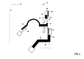
- a loudspeaker 10 is partially shown, which in the embodiment shown may be a woofer.
- the loudspeaker comprises a diaphragm 20 which is connected to a chassis or basket 30 via a flexible suspension 40.
- the flexible suspension 40 is connected and fixed to the chassis 30 using an axial movement of a locking element 50 relative to the chassis 30. With axial movement a movement in direction of the axis A of the loudspeaker is meant.
- the locking element 50 may be part of a locking ring which is provided on the whole perimeter of the chassis. However, it should be understood that the locking element or locking ring needs not necessarily be provided along the whole perimeter of the chassis.
- the chassis comprises a horizontal portion 31 followed by a vertical portion 32 as seen in a radial direction r of the loudspeaker.
- the vertical portion can comprise at its inner surface a threaded portion 33, e.g. a female thread.
- the locking element in the embodiment shown the locking ring, may comprise at its outer radial surface 51 a threaded portion 52 which cooperates with the threaded portion 33 to connect the locking ring to the chassis 30.
- the locking element is substantially L-shaped with a radial extending portion 53 and an axially extending portion 54 on which the threaded portion 52 is provided.
- the radial extending portion 53 of the locking element comprises a recess 55 which can receive a locking protrusion 41 provided at the outer radial end of the flexible suspension.
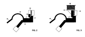
- the locking protrusion 41 extends into the recess 55.
- the radial extending portion 53 immobilizes the outer end of the flexible suspension, it provides a retaining strength in the axial direction when the diaphragm 20 not shown in Fig. 2 moves in the axial direction.
- This movement is inter alia guided by the convex part 42 of the suspension.
- a radial extending section 43 is followed by the axially extending locking protrusion 41.
- the locking protrusion extends into the front direction of the loudspeaker, the front direction indicating the direction to which the sound is emitted. It should be understood that the locking protrusion extending in the axial direction may also extend to the rear side of the loudspeaker. In this embodiment the chassis would contain a recess into which the locking protrusion would extend. In this embodiment the locking element 50 would not contain the recess 55. In still another embodiment the axially extending locking protrusion may extend in the front direction and the rear direction with the recess being provided in the locking element and the chassis to accommodate the different locking protrusions extending to the front and to the rear side of the loudspeaker.
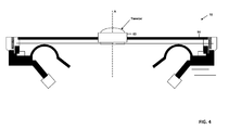
- the locking element 50 may at its front end furthermore contain a radially extending surface 55 which provides a support surface for a gasket 60 which may be fixed to the outer surface of the axially extending portion 55.
- the loudspeaker 10 is a combined loudspeaker comprising a woofer and a tweeter 60 which is supported by the locking ring 50.
- the suspension 400 also comprises a radial extending section 430 and an axially extending locking protrusion 410.
- the locking protrusion 410 is compared to the locking protrusion 41 of the embodiment described in connection with Figs. 1-4 , it can be seen that the locking protrusion has a greater dimension in the axial direction and in the radial direction. This is due to the fact that the locking protrusion is responsible for attaching the suspension to the chassis.
- the chassis 300 comprises a radially extending section 310 and an axially extending section 320. Furthermore, a radially inward extending locking arm 330 is provided comprising a locking nose 340.
- the flexible suspension is pushed into place radially by accommodating the locking protrusion 410 in a chamber 350, the chamber being built by the radially extending section 310, the axially extending section 320, the locking arm 330 and the locking nose 340.
- the locking nose 340 prevents the locking protrusion from moving axially back to the centre of the loudspeaker.
- the locking protrusion 410 completely fills chamber 350 so that the locking protrusion is immobilized in the chamber 350.
- the chassis here the components 310, 320, 330 and 340 also provide a retaining strength in the axial direction which is needed to keep the suspension in its place when the diaphragm 20 moves during operation.
- a gasket 60 is attached to the upper surface of the locking arm 330.
- a further embodiment is shown.
- the connection between the suspension 400 and the chassis corresponds to the embodiment described above in connection with Figs. 5 and 6 .
- the locking arm is part of a separate locking ring 500 which is connected to the chassis 600.
- the chassis and the locking ring comprise each locking components such as the recess 510 and the locking arm 610 with the protrusion 620. These locking components 510, 610 and 620 cooperate and help to secure the locking ring to the chassis, e.g. by clipping the locking ring 500 into place on the chassis 600.
- the locking ring 500 may comprise a lead-in 520 to more easily accommodate the locking ring 500 in the corresponding section of the chassis 600.
- the locking ring is shown in the connected state.
- a chassis 700 which again provides a chamber for accommodating the axially extending locking protrusion 410 including a locking nose 710 which provides a support surface for the radial inner surface of the locking protrusion 410.
- the chassis at its front part, furthermore contains severally radially extending sections 720 and 730. These radially extending sections 720 and 730 form an integral waveguide for the acoustic waves irradiated by the loudspeaker (Question to the inventor: Is this correct and can you add further details for this embodiment of the integral waveguide?)
- the flexible suspension can be made of rubber which has a flexibility that allows the deformation of the suspension and which allows it to be manoeuvred into the locked position, especially for the embodiments disclosed in connection with Figs. 5-9 .
- a radial force is applied to disengage the flexible suspension from the chassis.
- the flexibility is also needed in the embodiments described in connection with Figs. 1-4 , as the locking protrusion has to be located at the outer end of the chassis so that the locking protrusion can extend into the recess of the locking element.
- the above-described embodiments have the advantage that no adhesive is required for assembling the loudspeaker together. As a result, the rework or the recycling is easier. Furthermore, the locking element or locking ring can act as a support surface to mount a front gasket or it can act as an integral waveguide or auxiliary component mounted, e.g. for a tweeter carrier as shown in Fig. 4 .
Landscapes
- Engineering & Computer Science (AREA)
- Multimedia (AREA)
- Physics & Mathematics (AREA)
- Acoustics & Sound (AREA)
- Signal Processing (AREA)
- Details Of Audible-Bandwidth Transducers (AREA)
Abstract
The invention relates to a loudspeaker comprising a diaphragm, a loudspeaker chassis, a flexible suspension which is connected at its internal perimeter to the diaphragm and which is connected at its external perimeter to the loudspeaker chassis, wherein the flexible suspension comprises at its external perimeter a locking protrusion extending in an axial direction of the loudspeaker, and a locking element which cooperates with the locking protrusion in an assembled state of the loudspeaker in such a way that the locking element removably fixes the flexible suspension to the chassis and prevents the locking protrusion of the flexible suspension from moving in an axial and radial direction.
Description
- Various embodiments relate to a loudspeaker and to methods for assembling a loudspeaker.
- Typically, loudspeakers include a diaphragm or cone which is caused to vibrate by the movement of a voice coil connected to the cone. Typical loudspeakers comprise a rigid diaphragm with a flexible surround, also called flexible suspension. This flexible suspension is provided along the perimeter of the diaphragm to facilitate axial displacement of the diaphragm relative to the basket or chassis of the loudspeaker. The suspension is generally cemented along its internal perimeter to the diaphragm and along its external perimeter to the chassis of the loudspeaker. The flexible suspension is typically joined to the loudspeaker chassis with an adhesive.
- Gluing the surround to the chassis is a permanent fix and makes rework or recycling of the parts very difficult. Gluing the parts also requires highly controlled dispensing equipment, needing maintenance and consumables.
- Accordingly, a need exists to provide a loudspeaker which facilitates easy removal and/or reworking of the parts without damage to the suspension or chassis.
- This need is met by the features of the independent claims. Further embodiments are described in the dependent claims.
- According to a first aspect, a loudspeaker is provided comprising a diaphragm, a loudspeaker chassis and a flexible suspension which is connected at its internal perimeter to the diaphragm and which is connected at its external perimeter to the loudspeaker chassis. The flexible suspension comprises at its external perimeter a locking protrusion extending in a radial direction of the loudspeaker. The loudspeaker furthermore comprises a locking element which cooperates with the locking protrusion in an assembled state of the loudspeaker in such a way that the locking element removably fixes the flexible suspension to the chassis and prevents the locking protrusion of the flexible suspension from moving in an axial and radial direction.
- With the use of the locking element which cooperates with the locking protrusion, the flexible suspension can be attached to the chassis without adhesive. This facilitates the removal and the reworking of the parts without damage to the different parts, as a pure mechanical connection is obtained. This furthermore removes the need for adhesive and sophisticated glue dispensing equipment.
- In one embodiment the flexible suspension may comprise in the radial direction to the outside of the loudspeaker a radial extending section following by the locking protrusion. The locking protrusion can have a larger extension in the radial direction than the radial extension. The locking protrusion located at a greater external perimeter than the radial extending section provides an abutment surface which abuts against the locking element. A locking element has the corresponding surface against which the locking protrusion abuts.
- It is possible that the locking element is part of a locking ring attached to the front part of the loudspeaker chassis. This locking ring may be connected to the loudspeaker chassis using threaded parts provided on each of the locking ring and the loudspeaker chassis. In another embodiment the locking ring may be releasably connected to the chassis using further locking components provided on each of the locking ring and the chassis which cooperate to secure the locking ring to the chassis. By way of example, the locking ring may be clipped onto the chassis.
- The locking element may also provide a mounting surface for a gasket that may be mounted to the front side of the loudspeaker. The locking element may alone or together with the chassis provide a surface on which the gasket may be provided and secured to the chassis.
- The loudspeaker may be designed in such a way that in one embodiment the locking element is designed in such a way that it fixes the flexible suspension to the chassis by an axial movement of the locking element relative to the chassis. However, in another embodiment it is also possible that the locking element fixes the flexible suspension to the chassis by a radial movement of the suspension until the locking protrusion is fixedly connected to the chassis.
- The locking element may contain in the radial direction to the outside of the loudspeaker a radial extending portion followed by a recess into which the locking protrusion can extend. In the assembled state the radial extending section of the flexible suspension is sandwiched between the chassis and the radial extending portion of the locking element to hold the suspension down on the chassis during an axial movement of the suspension which occurs when the loudspeaker operates. The recess in the locking element provides a chamber to the locking protrusion and the flexible suspension is held in place with the locking protrusion being located in the recess.
- It is possible that the locking element comprises a locking arm which cooperates with the axial extending locking protrusion in such a way that the locking arm prevents the locking protrusion from moving at least in the radial direction. The locking arm may comprise a locking nose which immobilizes the locking protrusion. The locking arm may extend in the radial direction to the centre of the loudspeaker. Together with the chassis the locking arm can build a chamber in which the locking protrusion is located and which prevents the locking protrusion from moving in the axial direction. The locking element with the locking arm may be integrally formed with the chassis; however, in another embodiment the locking element with the locking arm may also be a separate element, e.g. part of a locking ring that is releasably connected to the chassis. According to a further aspect, a method for assembling a loudspeaker is provided, the loudspeaker comprising the diaphragm, the loudspeaker chassis and the flexible suspension. According to one step of the method, a radial outer end of the flexible suspension is positioned on the loudspeaker chassis, wherein the flexible suspension comprises in the radial direction to the outside of the loudspeaker a radial extending section followed by a locking protrusion which extends in an axial direction of the loudspeaker with a larger extension in the axial direction than the radial extension. In a further step the locking element is positioned in an axial direction onto the radial extending section of the flexible suspension. Furthermore, the flexible suspension is securely fixed to the chassis by an axial movement of the locking element relative to the chassis so that the locking element prevents the locking protrusion from moving in the radial and axial direction. The axial movement may be obtained by screwing the locking element onto the chassis or by clicking it onto the chassis. This method allows the attachment of the suspension to the chassis without the need of the adhesive to glue the suspension on the chassis. The above-discussed method can be easily reversed so that a rework or recycling of the parts becomes possible at lower costs.
- According to another method for assembling the loudspeaker, the locking protrusion is pushed into the outer axial direction of the loudspeaker until the locking protrusion is secured to the chassis by the locking arm, the locking arm again preventing the locking protrusion from moving at least in the radial direction. When the locking element is a part separate from the chassis, the locking element may furthermore be connected to the chassis, e.g. using a click mechanism provided on the chassis and on a locking element. The locking element may be connected to the chassis either with the locking protrusion already being secured by the locking arm or without the locking protrusion being secured by the locking arm, i.e. before the locking protrusion is pushed in the outer axial direction and secured to the locking element.
- It should be understood that each of the features described above and below may be used alone, in the described context or in combination with any other feature described above or below.
- The invention, together with further objects and attendant advantages, will best be understood by reference to the following detailed description of the preferred embodiments taken in conjunction with the accompanying drawings.
-
-
Fig. 1 shows in a side elevation view a first embodiment how a flexible suspension is connected to a chassis using axial movement of a locking element relative to the chassis, -
Fig. 2 shows the loudspeaker ofFig. 1 in an assembled state, -
Fig. 3 shows a further embodiment of a locking element with a connected gasket, -
Fig. 4 shows a partial side elevation view of a loudspeaker with a connected tweeter, -
Fig. 5 shows another embodiment in which the flexible suspension is connected to the chassis by a radial movement of the suspension, -
Fig. 6 shows the embodiment ofFig. 5 in an assembled state with a gasket connected on the locking element, -
Fig. 7 shows another embodiment where the locking element is a separate part and clicked onto the chassis, -
Fig. 8 shows the embodiment ofFig. 7 in a finally assembled state, and -
Fig. 9 shows another embodiment where the locking element is part of an integral waveguide. - With reference to the drawings, a first embodiment is disclosed in connection with
Figs. 1-4 . InFig. 1 aloudspeaker 10 is partially shown, which in the embodiment shown may be a woofer. The loudspeaker comprises adiaphragm 20 which is connected to a chassis orbasket 30 via aflexible suspension 40. In the embodiment shown inFigs. 1-4 , theflexible suspension 40 is connected and fixed to thechassis 30 using an axial movement of a lockingelement 50 relative to thechassis 30. With axial movement a movement in direction of the axis A of the loudspeaker is meant. As indicated by thearrows 11 and 12, theflexible suspension 40 is pushed into place axially maintaining a retaining strength in the axial direction in which thediaphragm 20 and thus the suspension moves during operation. The lockingelement 50 may be part of a locking ring which is provided on the whole perimeter of the chassis. However, it should be understood that the locking element or locking ring needs not necessarily be provided along the whole perimeter of the chassis. The chassis comprises ahorizontal portion 31 followed by avertical portion 32 as seen in a radial direction r of the loudspeaker. The vertical portion can comprise at its inner surface a threadedportion 33, e.g. a female thread. The locking element, in the embodiment shown the locking ring, may comprise at its outer radial surface 51 a threadedportion 52 which cooperates with the threadedportion 33 to connect the locking ring to thechassis 30. In the embodiment shown the locking element is substantially L-shaped with aradial extending portion 53 and anaxially extending portion 54 on which the threadedportion 52 is provided. Theradial extending portion 53 of the locking element comprises arecess 55 which can receive a lockingprotrusion 41 provided at the outer radial end of the flexible suspension. - As can be seen inter alia from
Fig. 2 , in the assembled state when the locking element, in the embodiment shown the locking ring, is screwed onto the chassis the lockingprotrusion 41 extends into therecess 55. Theradial extending portion 53 immobilizes the outer end of the flexible suspension, it provides a retaining strength in the axial direction when thediaphragm 20 not shown inFig. 2 moves in the axial direction. This movement is inter alia guided by theconvex part 42 of the suspension. Following the convex or half-circular shapedpart 42, aradial extending section 43 is followed by the axially extending lockingprotrusion 41. In the embodiment shown the locking protrusion extends into the front direction of the loudspeaker, the front direction indicating the direction to which the sound is emitted. It should be understood that the locking protrusion extending in the axial direction may also extend to the rear side of the loudspeaker. In this embodiment the chassis would contain a recess into which the locking protrusion would extend. In this embodiment the lockingelement 50 would not contain therecess 55. In still another embodiment the axially extending locking protrusion may extend in the front direction and the rear direction with the recess being provided in the locking element and the chassis to accommodate the different locking protrusions extending to the front and to the rear side of the loudspeaker. - As shown in
Fig. 3 , the lockingelement 50 may at its front end furthermore contain aradially extending surface 55 which provides a support surface for agasket 60 which may be fixed to the outer surface of theaxially extending portion 55. - In connection with
Fig. 4 a further embodiment is shown in which theloudspeaker 10 is a combined loudspeaker comprising a woofer and atweeter 60 which is supported by the lockingring 50. - In connection with
Figs. 5 and 6 a further embodiment is shown. In this embodiment thesuspension 400 also comprises aradial extending section 430 and an axially extending lockingprotrusion 410. When the lockingprotrusion 410 is compared to the lockingprotrusion 41 of the embodiment described in connection withFigs. 1-4 , it can be seen that the locking protrusion has a greater dimension in the axial direction and in the radial direction. This is due to the fact that the locking protrusion is responsible for attaching the suspension to the chassis. Thechassis 300 comprises aradially extending section 310 and anaxially extending section 320. Furthermore, a radially inward extendinglocking arm 330 is provided comprising a lockingnose 340. The flexible suspension is pushed into place radially by accommodating the lockingprotrusion 410 in achamber 350, the chamber being built by theradially extending section 310, theaxially extending section 320, the lockingarm 330 and the lockingnose 340. The lockingnose 340 prevents the locking protrusion from moving axially back to the centre of the loudspeaker. The lockingprotrusion 410 completely fillschamber 350 so that the locking protrusion is immobilized in thechamber 350. - Furthermore, with the L-shaped form of the
radial extending section 430 and the lockingprotrusion 410 the chassis, here thecomponents diaphragm 20 moves during operation. - In the embodiment of
Fig. 6 agasket 60 is attached to the upper surface of thelocking arm 330. - In connection with
Figs. 7 and 8 a further embodiment is shown. In this embodiment the connection between thesuspension 400 and the chassis corresponds to the embodiment described above in connection withFigs. 5 and 6 . However, in the embodiments ofFigs. 7 and 8 the locking arm is part of aseparate locking ring 500 which is connected to thechassis 600. The chassis and the locking ring comprise each locking components such as the recess 510 and thelocking arm 610 with theprotrusion 620. These lockingcomponents locking ring 500 into place on thechassis 600. To facilitate the connection, thelocking ring 500 may comprise a lead-in 520 to more easily accommodate thelocking ring 500 in the corresponding section of thechassis 600. In the embodiment ofFig. 8 the locking ring is shown in the connected state. - In connection with
Fig. 9 a further embodiment is shown. Thesuspension 400 corresponds to the suspension explained above in connection withFigs. 5-8 . In the embodiment shown inFig. 9 achassis 700 is provided which again provides a chamber for accommodating the axially extending lockingprotrusion 410 including a lockingnose 710 which provides a support surface for the radial inner surface of the lockingprotrusion 410. The chassis, at its front part, furthermore contains severally radially extendingsections sections - In all the embodiments the flexible suspension can be made of rubber which has a flexibility that allows the deformation of the suspension and which allows it to be manoeuvred into the locked position, especially for the embodiments disclosed in connection with
Figs. 5-9 . For a removal of the suspension, for the embodiments shown inFigs. 5-9 a radial force is applied to disengage the flexible suspension from the chassis. The flexibility is also needed in the embodiments described in connection withFigs. 1-4 , as the locking protrusion has to be located at the outer end of the chassis so that the locking protrusion can extend into the recess of the locking element. - The above-described embodiments have the advantage that no adhesive is required for assembling the loudspeaker together. As a result, the rework or the recycling is easier. Furthermore, the locking element or locking ring can act as a support surface to mount a front gasket or it can act as an integral waveguide or auxiliary component mounted, e.g. for a tweeter carrier as shown in
Fig. 4 .
Claims (17)
- A loudspeaker comprising:- a diaphragm,- a loudspeaker chassis,- a flexible suspension which is connected at its internal perimeter to the diaphragm and which is connected at its external perimeter to the loudspeaker chassis, wherein the flexible suspension comprises at its external perimeter a locking protrusion extending in an axial direction of the loudspeaker,- a locking element which cooperates with the locking protrusion in an assembled state of the loudspeaker in such a way that the locking element removably fixes the flexible suspension to the chassis and prevents the locking protrusion of the flexible suspension from moving in an axial and radial direction.
- The loudspeaker according to claim 1, wherein the flexible suspension comprises in the radial direction to the outside of the loudspeaker a radial extending section followed by the locking protrusion, wherein the locking protrusion has a larger extension in the axial direction than the radial extension.
- The loudspeaker according to claim 1 or 2, wherein the locking element is part of a locking ring attached to a front part of the loudspeaker chassis.
- The loudspeaker according to any of the preceding claims, wherein a gasket is arranged on the front side on the locking element.
- The loudspeaker according to any of the preceding claims, wherein the locking element is designed in such a way that it fixes the flexible suspension to the chassis by an axial movement of the locking element relative to the chassis.
- The loudspeaker according to any of the preceding claims, wherein the locking element comprises a threaded portion which cooperates with a complementary threaded portion provided at the chassis to secure the locking element to the chassis.
- The loudspeaker according to any of claims 2 to 6, wherein the locking element comprises in the radial direction to the outside of the loudspeaker a radial extending portion followed by a recess into which the locking protrusion extends.
- The loudspeaker according to claim 7, wherein the radial extending section of the flexible suspension is sandwiched between the chassis and the radial extending portion of the locking element to hold the suspension down on the chassis during axial movement of the suspension.
- The loudspeaker according to any of claims 1 to 4 , wherein the locking element comprises a locking arm which cooperates with the axially extending locking protrusion in such a way that the locking arm prevents the locking protrusion of moving at least in the radial direction.
- The loudspeaker according to claim 9, wherein the locking arm is extending in the radial direction to a centre of the loudspeaker.
- The loudspeaker according to claim 9 or 10, wherein the locking arm together with the chassis build a chamber in which the locking protrusion is located and which prevents the locking protrusion from moving in the axial direction.
- The loudspeaker according to any of claims 9 to 11, wherein the locking element is integrally formed with the chassis.
- The loudspeaker according to claim 10 or 11, wherein the locking arm is part of a locking ring that is releasably connected to the chassis using further locking components provided on each of the locking ring and the chassis and which cooperate to secure the locking ring to the chassis.
- A method for assembling a loudspeaker, the loudspeaker comprising a diaphragm, a loudspeaker chassis and a flexible suspension, the method comprising the step of- positioning a radial outer end of a flexible suspension on the loudspeaker chassis, the flexible suspension comprising, in a radial direction to the outside of the loudspeaker, a radial extending section followed by a locking protrusion extending in an axial direction of the loudspeaker,- positioning a locking element in the axial direction onto the radial extending section of the flexible suspension,- securely fixing the flexible suspension to the chassis by an axial movement of the locking element relative to the chassis so that the locking element prevents the locking protrusion from moving in the radial and axial direction.
- The method according to claim 14, wherein the locking element, in the fixed position, presses the radial extending section of the suspension onto the chassis and prevents the locking protrusion from moving in the radial direction.
- A method for assembling a loudspeaker, the loudspeaker comprising a diaphragm, a flexible suspension with which the diaphragm is secured to a loudspeaker chassis, a locking element comprising a locking arm with which the suspension is secured to the chassis, the flexible suspension comprising a locking protrusion extending in the axial direction of the loudspeaker, the method comprising the step of:- pushing the locking protrusion into the outer axial direction of the loudspeaker until the locking protrusion is secured to the chassis by the locking arm, the locking arm preventing the locking protrusion from moving at least in the radial direction.
- The method according to claim 16, wherein the locking element is part separate from the chassis, the method further comprising the step of connecting the locking element to the chassis.
Priority Applications (1)
| Application Number | Priority Date | Filing Date | Title |
|---|---|---|---|
| EP13181410.5A EP2840804A1 (en) | 2013-08-22 | 2013-08-22 | Loudspeaker and method for assembling a loudspeaker |
Applications Claiming Priority (1)
| Application Number | Priority Date | Filing Date | Title |
|---|---|---|---|
| EP13181410.5A EP2840804A1 (en) | 2013-08-22 | 2013-08-22 | Loudspeaker and method for assembling a loudspeaker |
Publications (1)
| Publication Number | Publication Date |
|---|---|
| EP2840804A1 true EP2840804A1 (en) | 2015-02-25 |
Family
ID=49000870
Family Applications (1)
| Application Number | Title | Priority Date | Filing Date |
|---|---|---|---|
| EP13181410.5A Withdrawn EP2840804A1 (en) | 2013-08-22 | 2013-08-22 | Loudspeaker and method for assembling a loudspeaker |
Country Status (1)
| Country | Link |
|---|---|
| EP (1) | EP2840804A1 (en) |
Cited By (2)
| Publication number | Priority date | Publication date | Assignee | Title |
|---|---|---|---|---|
| EP3182726A1 (en) * | 2015-12-17 | 2017-06-21 | Delphi Technologies, Inc. | Sound transmission device |
| GB2626085A (en) * | 2022-12-30 | 2024-07-10 | Tymphany Hk Ltd | Vibration module, speaker having the same, and manufacturing method thereof |
Citations (2)
| Publication number | Priority date | Publication date | Assignee | Title |
|---|---|---|---|---|
| US3892289A (en) * | 1973-07-02 | 1975-07-01 | William L Rollins | Loudspeaker |
| US20050180590A1 (en) * | 2004-02-18 | 2005-08-18 | Jl Audio, Inc. | Loudspeaker with field replaceable parts and method of assembly |
-
2013
- 2013-08-22 EP EP13181410.5A patent/EP2840804A1/en not_active Withdrawn
Patent Citations (2)
| Publication number | Priority date | Publication date | Assignee | Title |
|---|---|---|---|---|
| US3892289A (en) * | 1973-07-02 | 1975-07-01 | William L Rollins | Loudspeaker |
| US20050180590A1 (en) * | 2004-02-18 | 2005-08-18 | Jl Audio, Inc. | Loudspeaker with field replaceable parts and method of assembly |
Cited By (4)
| Publication number | Priority date | Publication date | Assignee | Title |
|---|---|---|---|---|
| EP3182726A1 (en) * | 2015-12-17 | 2017-06-21 | Delphi Technologies, Inc. | Sound transmission device |
| FR3046005A1 (en) * | 2015-12-17 | 2017-06-23 | Delphi Tech Inc | SOUND TRANSMITTING DEVICE |
| GB2626085A (en) * | 2022-12-30 | 2024-07-10 | Tymphany Hk Ltd | Vibration module, speaker having the same, and manufacturing method thereof |
| GB2626085B (en) * | 2022-12-30 | 2025-01-08 | Tymphany Hk Ltd | Vibration module, speaker having the same, and manufacturing method thereof |
Similar Documents
| Publication | Publication Date | Title |
|---|---|---|
| US20160127832A1 (en) | Speaker diaphragm supporting structure | |
| US10034094B2 (en) | Low-profile loudspeaker | |
| US8910744B2 (en) | Speaker unit | |
| JPWO2016056183A1 (en) | Loudspeaker and loudspeaker structure | |
| US20200213743A1 (en) | Electro-acoustic driver having compliant diaphragm with stiffening element | |
| US20190020945A1 (en) | Passive radiators and related devices | |
| US20080002850A1 (en) | Speaker and manufacturing method | |
| AU2018292941A1 (en) | Sound transducer arrangement having an MEMS unit | |
| KR101169381B1 (en) | Method for manufacturing a speaker and an assembling zig used in the same | |
| KR101443250B1 (en) | Lens barrel assembly having improved performance of infra red filter assembling | |
| CN105308986B (en) | speaker device | |
| WO2018011912A1 (en) | Loudspeaker, vibration system unit, and magnetic circuit unit | |
| US20130313208A1 (en) | Outdoor unit system and holder for outdoor unit | |
| KR101100256B1 (en) | Speaker manufacturing method and assembly jig used therein | |
| JP2005268986A (en) | Microphone device | |
| ITAN20140056U1 (en) | LOUDSPEAKER WITH FRONT LOADED MAGNET. | |
| US12563344B2 (en) | Speaker device | |
| JP2005318279A (en) | Loudspeaker | |
| KR200367584Y1 (en) | Screw fixing unit for assembling the frame of electronic machine | |
| JP4891760B2 (en) | In-vehicle speaker mounting structure | |
| HK1235956A1 (en) | Low-profile loudspeaker | |
| EP2675013A1 (en) | Outdoor unit system and holder for outdoor unit | |
| JP4513828B2 (en) | Speaker mounting structure and thin display device | |
| JP2008167238A (en) | Speaker apparatus | |
| JP2015140850A (en) | Vibration-proofing device |
Legal Events
| Date | Code | Title | Description |
|---|---|---|---|
| PUAI | Public reference made under article 153(3) epc to a published international application that has entered the european phase |
Free format text: ORIGINAL CODE: 0009012 |
|
| 17P | Request for examination filed |
Effective date: 20130822 |
|
| AK | Designated contracting states |
Kind code of ref document: A1 Designated state(s): AL AT BE BG CH CY CZ DE DK EE ES FI FR GB GR HR HU IE IS IT LI LT LU LV MC MK MT NL NO PL PT RO RS SE SI SK SM TR |
|
| AX | Request for extension of the european patent |
Extension state: BA ME |
|
| STAA | Information on the status of an ep patent application or granted ep patent |
Free format text: STATUS: THE APPLICATION IS DEEMED TO BE WITHDRAWN |
|
| 18D | Application deemed to be withdrawn |
Effective date: 20150826 |