EP2840768A2 - Image reading apparatus efficiently illuminating light - Google Patents
Image reading apparatus efficiently illuminating light Download PDFInfo
- Publication number
- EP2840768A2 EP2840768A2 EP14181734.6A EP14181734A EP2840768A2 EP 2840768 A2 EP2840768 A2 EP 2840768A2 EP 14181734 A EP14181734 A EP 14181734A EP 2840768 A2 EP2840768 A2 EP 2840768A2
- Authority
- EP
- European Patent Office
- Prior art keywords
- light
- image
- guiding body
- pair
- original document
- Prior art date
- Legal status (The legal status is an assumption and is not a legal conclusion. Google has not performed a legal analysis and makes no representation as to the accuracy of the status listed.)
- Granted
Links
Images





Classifications
-
- H—ELECTRICITY
- H04—ELECTRIC COMMUNICATION TECHNIQUE
- H04N—PICTORIAL COMMUNICATION, e.g. TELEVISION
- H04N1/00—Scanning, transmission or reproduction of documents or the like, e.g. facsimile transmission; Details thereof
- H04N1/024—Details of scanning heads ; Means for illuminating the original
- H04N1/028—Details of scanning heads ; Means for illuminating the original for picture information pick-up
- H04N1/02815—Means for illuminating the original, not specific to a particular type of pick-up head
-
- H—ELECTRICITY
- H04—ELECTRIC COMMUNICATION TECHNIQUE
- H04N—PICTORIAL COMMUNICATION, e.g. TELEVISION
- H04N1/00—Scanning, transmission or reproduction of documents or the like, e.g. facsimile transmission; Details thereof
-
- H—ELECTRICITY
- H04—ELECTRIC COMMUNICATION TECHNIQUE
- H04N—PICTORIAL COMMUNICATION, e.g. TELEVISION
- H04N1/00—Scanning, transmission or reproduction of documents or the like, e.g. facsimile transmission; Details thereof
- H04N1/04—Scanning arrangements, i.e. arrangements for the displacement of active reading or reproducing elements relative to the original or reproducing medium, or vice versa
Definitions
- an illumination device In an image reading apparatus such as a scanner and a copier, an illumination device is mounted.
- the illumination device irradiates a light to a document for optically reading the image of the document placed on a reading surface.
- a light source for this illumination device a light emitting diode (LED) is used.
- the LED has an advantage of high luminous efficiency.
- the LED is a point light source, a bar-shaped light guiding body and the LED are combined to generate a line-shaped illuminating light.
- the light guiding body includes an incident surface and a strip-shaped emission surface.
- the incident surface is arranged in an end portion of the light guiding body, and receives the illuminating light emitted from the LED.
- the emission surface extends along the longitudinal direction of the light guiding body, and causes emission of the illuminating light.
- the light guiding body includes two emission surfaces.
- the light emitted from one emission surface is directly irradiated to the document.
- the light emitted from the other emission surface is reflected at the reflective plate, and then irradiated to the document sheet.
- the lights from the two directions intersecting with each other are irradiated to the document.
- An image reading apparatus for reading an image of an original document includes a document placement surface, an illumination unit, a light-receiving unit, and an illumination control unit.
- the illumination unit is arranged to face the document placement surface.
- the illumination unit is configured to irradiate an illuminating light to the original document.
- the light-receiving unit is configured to receive a reflected light from the original document and convert the reflected light into an electrical signal.
- the illumination control unit is configured to control the illumination unit corresponding to a reading mode where the image of the original document is read.
- the illumination unit includes a first light guiding body in a bar shape, a second light guiding body, a pair of first light sources, and a pair of second light sources.
- the first light guiding body is in a bar shape extended in a first direction that includes: a pair of first incident surfaces arranged in both end portions of the first light guiding body in the first direction, the first incident surface being configured to receive a light injected along the first direction; and a first emission surface disposed to extend along the first direction, the first emission surface being configured to emit the light in a second direction intersecting with the first direction, the first light guiding body being configured to irradiate a light to the original document along the second direction.
- the second light guiding body is arranged at a distance from the first light guiding body, the second light guiding body being in a bar shape extended in the first direction, the second light guiding body including: a pair of second incident surfaces arranged in both end portions of the second light guiding body in the first direction, the second incident surface being configured to receive a light injected along the first direction; and a second emission surface disposed to extend along the first direction, the second emission surface being configured to emit the light in a third direction intersecting with the first direction, the second light guiding body being configured to irradiate a light to the original document along the third direction.
- the pair of first light sources is arranged to face the pair of the respective first incident surfaces of the first light guiding body to emit illuminating lights to be injected into the first incident surfaces.
- the pair of second light sources is arranged to face the pair of the respective second incident surfaces of the second light guiding body to emit illuminating lights to be injected into the second incident surface.
- the illumination control unit is configured to control light-emitting operations of the first light source and the second light source corresponding to the reading mode.
- FIG. 1 illustrates the internal structure of an image forming apparatus 1 that includes an image reading apparatus 22 according to one embodiment of the disclosure.
- the image forming apparatus 1 for example, what is called a copier of an in-barrel paper discharge type is illustrated.
- the apparatus to which the image reading apparatus 22 according to the disclosure is applied is not limited to the copier, and may be, for example, a scanner apparatus, a facsimile apparatus, or a multi-functional peripheral.
- the image forming apparatus 1 includes a housing 2.
- the housing 2 has a chassis structure in an approximately rectangular parallelepiped shape, and has an in-barrel space (in-barrel paper discharge unit 24).
- the housing 2 includes a lower chassis (apparatus main body 21), an upper chassis (image reading apparatus 22), and a connection chassis 23.
- the lower chassis houses various devices for image formation.
- the upper chassis is arranged on the upper side of the apparatus main body 21.
- the connection chassis 23 connects the apparatus main body 21 and the image reading apparatus 22 together.
- the image reading apparatus 22 optically reads the image of a document sheet (original document) to generate image data corresponding to the document image.
- the apparatus main body 21 performs a process for forming a toner image on a sheet based on the image data.
- the in-barrel paper discharge unit 24 is disposed between the apparatus main body 21 and the image reading apparatus 22, the in-barrel paper discharge unit 24 is disposed. To the in-barrel paper discharge unit 24, the sheet after the image formation is discharged.
- the connection chassis 23 is arranged on a side of the right side surface of the housing 2, and includes a discharge port 961 for discharging a sheet to the in-barrel paper discharge unit 24.
- toner containers 99Y, 99M, 99C, and 99Bk Inside of the apparatus main body 21, toner containers 99Y, 99M, 99C, and 99Bk, an intermediate transfer unit 92, an image forming unit 93, an exposure unit 94, and a sheet feed cassette 211 are housed in this order from the left.
- the image forming unit 93 forms an image on a sheet based on the image data output from the image reading apparatus 22.
- the image forming unit 93 includes four image formation units 10Y, 10M, 10C, and 10Bk for forming a full-color toner image.
- the image formation units 10Y, 10M, 10C, and 10Bk form respective toner images of yellow (Y), magenta (M), cyan (C), and black (Bk).
- Each of the image formation units 10Y, 10M, 10C, and 10Bk includes a photoreceptor drum 11 and a charger 12, a developing device 13, a primary transfer roller 14, and a cleaning device 15 arranged in the peripheral area of this photoreceptor drum 11.
- the photoreceptor drum 11 rotates around its own axis. On the circumference surface of the photoreceptor drum 11, an electrostatic latent image and a toner image are formed.
- the charger 12 uniformly charges the surface of the photoreceptor drum 11. The circumference surface of the photoreceptor drum 11 after the charging is exposed by the exposure unit 94, and thus an electrostatic latent image is formed.
- the developing device 13 supplies the toner to the circumference surface of the photoreceptor drum 11 so as to develop the electrostatic latent image formed on the photoreceptor drum 11.
- the developing device 13 includes agitation rollers 16 and 17, a magnetic roller 18, and a developing roller 19.
- the agitation rollers 16 and 17 circulatively convey the two-component developer while agitating it, so as to charge the toner.
- On the circumference surface of the magnetic roller 18, a two-component developer layer is supported.
- On the circumference surface of the developing roller 19, a toner layer is supported.
- the toner layer is formed by delivery and receipt of the toner due to the difference in electric potential between the magnetic roller 18 and the developing roller 19.
- the toner on the developing roller 19 is supplied to the circumference surface of the photoreceptor drum 11, so as to develop the electrostatic latent image.
- the primary transfer roller 14 sandwich an intermediate transfer belt 921 included in the intermediate transfer unit 92 so as to form a nip portion together with the photoreceptor drum 11, and primarily transfers the toner image on the photoreceptor drum 11 onto the intermediate transfer belt 921.
- the cleaning device 15 cleans the circumference surface of the photoreceptor drum 11 after the transferring of the toner image.
- the yellow toner container 99Y, the magenta toner container 99M, the cyan toner container 99C, and the black toner container 99Bk reserve toners of respective colors.
- the toners of the respective colors are supplied through a supply path (not illustrated) to the developing devices 13 of the image formation units 10Y, 10M, 10C, and 10Bk corresponding to the respective colors of Y, M, C, and Bk.
- the exposure unit 94 includes various kinds of optical system equipment, for example, a light source, a polygon mirror, a reflective mirror, and a deflecting mirror.
- the exposure unit 94 irradiates the light based on the image data of the document image to the respective circumference surfaces of the photoreceptor drums 11 disposed in the image formation units 10Y, 10M, 10C, and 10Bk, so as to form an electrostatic latent image.
- the intermediate transfer unit 92 includes an intermediate transfer belt 921, a drive roller 922, and a driven roller 923.
- On the intermediate transfer belt 921 respective toner images from the plurality of photoreceptor drums 11 are superimposed (in primary transfer).
- the superimposed toner images are secondarily transferred to a sheet to be supplied from the sheet feed cassette 211 or a sheet feed tray 30 in a secondary transfer unit 98.
- the drive roller 922 and the driven roller 923 that circularly drive the intermediate transfer belt 921 are rotatably supported by the apparatus main body 21.
- the sheet feed cassette 211 houses a sheet bundle formed by laminating a plurality of sheets.
- a pickup roller 212 is arranged in the upper portion of the sheet feed cassette 211 on the right edge side. Driving the pickup roller 212 feeds the sheet in the uppermost layer of the sheet bundle within the sheet feed cassette 211 one by one, so as to carry the fed sheet in a carry-in conveyance path 26.
- a paper feeding unit 40 is disposed on the right-side surface of the apparatus main body 21, .
- the paper feeding unit 40 includes the sheet feed tray 30 for manual paper feeding. The sheet placed on the sheet feed tray 30 is carried in the carry-in conveyance path 26 by the driving of a paper feed roller 41 of the paper feeding unit 40.
- a sheet conveyance path 28 is disposed at the downstream side of the carry-in conveyance path 26, a sheet conveyance path 28 is disposed.
- the sheet conveyance path 28 is extended to the discharge port 961 via the secondary transfer unit 98, a fixing unit 97, and a sheet discharge unit 96, which are described later.
- the upstream portion of the sheet conveyance path 28 is formed between the inner wall formed in the apparatus main body 21 and the inner wall forming the internal surface of a reverse conveying unit 29.
- the outer surface of the reverse conveying unit 29 forms one surface of a reverse conveyance path 291.
- a sheet is inversely conveyed at the time of duplex printing.
- a registration roller pair 27 is arranged at the upstream side of the secondary transfer unit 98 in the sheet conveyance path 28 . The sheet is once stopped by the registration roller pair 27 for skew correction. Subsequently, the sheet is sent out to the secondary transfer unit 98 at predetermined timing for image transfer.
- the connection chassis 23 houses the fixing unit 97 and the sheet discharge unit 96 inside.
- the fixing unit 97 includes a fixing roller and a pressure roller.
- the fixing unit 97 heats and applies pressure to the sheet on which the toner image is secondarily transferred, so as to perform a fixing process.
- the sheet with the color image after the fixing process is discharged from the discharge port 961 toward the in-barrel paper discharge unit 24 by the sheet discharge unit 96.
- the image reading apparatus 22 includes a first contact glass 222 and a second contact glass 223.
- the first contact glass 222 and the second contact glass 223 are fit into a top surface 221 of the upper chassis.
- ADF automatic document feed
- the first contact glass 222 is disposed for reading a document sheet to be automatically fed from the ADF.
- the second contact glass 223 is disposed for reading the placed document sheet.
- the image reading apparatus 22 may include a document cover 22A (see FIG. 10 ) instead of the ADF.
- the document cover 22A can be opened with respect to the top surface portion of the image reading apparatus 22.
- the document cover 22A is set to an open state, a document sheet is placed on the second contact glass 223 by the user.
- the document cover 22A is set to a closed state, the document sheet is pressed and fixed by the document cover 22A.
- the image reading apparatus 22 includes a first moving carriage 224, a second moving carriage 225, a condensing lens unit 228, and an imaging device 229 (light-receiving unit), which are housed within the upper chassis.
- the first moving carriage 224 includes an illumination device 50, which will be described later, and a first reflective mirror 226.
- the second moving carriage 225 includes a second reflective mirror 227A and a third reflective mirror 227B for reversing the optical path.
- the first moving carriage 224 reciprocates in the right-left direction (sub-scanning direction) along the inferior surfaces of the first contact glass 222 and the second contact glass 223.
- the second moving carriage 225 reciprocates by a movement amount that is a half of the movement amount of the first moving carriage 224 in the right-left direction.
- the first moving carriage 224 moves to a position immediately below the first contact glass 222 and then is set to a resting state. In this resting state, a light is emitted from the illumination device 50 toward the document sheet.
- the first moving carriage 224 moves from a position immediately below the left end of the second contact glass 223 toward the right side corresponding to the size of the document sheet. During this movement, a light is emitted from the illumination device 50 toward the document sheet.
- the second moving carriage 225 moves to the right side by the movement amount that is a half of the movement amount of the first moving carriage 224, following the first moving carriage 224.
- the illumination device 50 irradiates an illuminating light in a line shape extended in the main-scanning direction (front-rear direction) to the document sheet (original document) as an irradiation target object.
- the illumination device 50 is arranged to face the first contact glass 222 or the second contact glass 223. Specifically, the illumination device 50 emits the illuminating light to the document sheet that passes above the first contact glass 222 by automatic feeding or the document sheet that is placed on the second contact glass 223 by manual placement, for optically reading the document-sheet image.
- the first reflective mirror 226 reflects the reflected light of the illuminating light that is emitted toward the document sheet by the illumination device 50 toward the second reflective mirror 227A of the second moving carriage 225.
- the second reflective mirror 227A reflects the reflected light that is reflected by the first reflective mirror 226 toward the third reflective mirror 227B.
- the third reflective mirror 227B reflects the reflected light toward the condensing lens unit 228.
- the condensing lens unit 228 forms a light image of the reflected light that is reflected by the third reflective mirror 227B on the imaging surface of the imaging device 229.
- the imaging device 229 is formed of a charge coupled device (CCD) and similar member, and receives the reflected light, and photoelectrically converts the received light into an analog electrical signal. This analog electrical signal is converted into a digital electrical signal by an A/D converter circuit (not illustrated). Subsequently, the digital electrical signal is input to the above-described exposure unit 94 as the image data.
- CCD charge coupled device
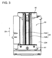
- FIG. 2 and FIG. 3 each perspectively illustrate the illumination device 50 on the first moving carriage 224.
- FIG. 4 perspectively illustrates a first light guiding body 52A (or a second light guiding body 52B) of the illumination device 50.
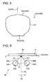
- FIG. 5 illustrates a cross section of the first light guiding body 52A (or a second light guiding body 52B).
- the reference numerals for the second light guiding body 52B are illustrated in brackets.
- FIG. 6 illustrates schematic cross sections of the respective light guiding bodies of the illumination device 50.
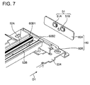
- FIG. 7 and FIG. 8 each perspectively illustrate an exploded schematic view of the illumination device 50.
- the illumination device 50 irradiates a light while setting a focal position to the document sheet (irradiation target object) arranged on the first contact glass 222 or the second contact glass 223 (predetermined arrangement surface).
- the illumination device 50 is arranged on the first moving carriage 224 along the main-scanning direction (the first direction illustrated by an arrow D1 in FIG. 2 and FIG. 3 ).
- the illumination device 50 includes a light source 51 (see FIG. 7 ) and a light guiding body 52.
- the light guiding body 52 causes the propagation of the illuminating light emitted from the light source 51 and converts this illuminating light into an illuminating light in a line shape, and then emits the converted illuminating light.
- the light source 51 includes a first light source 51A and a second light source 51B.
- the light guiding body 52 includes a first light guiding body 52A and a second light guiding body 52B.
- the first light guiding body 52A has a bar shape extended in the first direction.
- the first light guiding body 52A includes a first incident surface 54A and a first emission surface 56A (see FIG. 4 ).
- the first incident surface 54A is arranged in the end portion of the first light guiding body 52A in the first direction.
- a light is injected into the first incident surface 54A.
- a pair of the first incident surfaces 54A are arranged on both end portions of the first light guiding body 52A in the first direction.
- the first emission surface 56A is disposed to extend along the first direction.
- the first emission surface 56A emits the light in a second direction (illustrated by an arrow D2 in FIG. 4 and FIG. 6 ) intersecting with the first direction. Then, the first light guiding body 52A irradiates the light to the document sheet from the second direction.
- the second light guiding body 52B is arranged at a distance from the first light guiding body 52A.
- the second light guiding body 52B has a bar shape extended in the first direction.
- the second light guiding body 52B includes a second incident surface 54B and a second emission surface 56B.
- the second incident surface 54B is arranged in the end portion of the second light guiding body 52B in the first direction.
- a light is injected into the second incident surface 54B.
- a pair of the second incident surfaces 54B are arranged on both end portions of the second light guiding body 52B in the first direction.
- the second emission surface 56B is disposed to extend along the first direction.
- the second emission surface 56B emits the light in a third direction (illustrated by an arrow D3 in FIG. 4 and FIG. 6 ), which will be described later, intersecting with the first direction. Then, the second light guiding body 52B irradiates the light to the document sheet from the third direction.
- the light source 51 (the first light source 51A and the second light source 51 B) has a thin circular plate shape, and includes a white light emitting diode (LED) 51 L, which emits a white-colored light (see FIG. 4 ).
- LED white light emitting diode
- the pair of the first light sources 51A and the pair of the second light sources 51 B are respectively arranged in both the end portions of the first light guiding body 52A and both the end portions of the second light guiding body 52B. That is, the pair of the first light sources 51A are arranged to face the pair of the respective first incident surfaces 54A in the first light guiding body 52A. The pair of the first light sources 51A emit illuminating lights to be injected into the first incident surfaces 54A. The pair of the second light sources 51B are arranged to face the pair of the respective second incident surfaces 54B in the second light guiding body 52B. The pair of the second light sources 51 B emit illuminating lights to be injected into the second incident surfaces 54B.
- the second light guiding body 52B has a configuration similar to that of the first light guiding body 52A.
- the first light guiding body 52A and the second light guiding body 52B are different from each other in arrangement in the illumination device 50. Accordingly, in FIG. 4 and FIG. 5 , the structure of the first light guiding body 52A will be mainly described as an example.
- the first light guiding body 52A is formed of a translucent resin material such as acrylic resin.
- the first light guiding body 52A has a bar shape extended in the main-scanning direction (first direction), and includes a main unit 53 and the pair of the first incident surfaces 54A.
- the main unit 53 guides illuminating lights emitted from the first light sources 51A.
- the pair of the first incident surfaces 54A are both of the end surfaces of the main unit 53 in the first direction, and the illuminating lights are injected into these first incident surfaces 54A.
- the above-described pair of the first light sources 51A have light-emitting surfaces arranged to face the pair of the respective first incident surfaces 54A. In FIG. 4 , the first light source 51A on the distal end side in the first direction is not illustrated in the drawing.
- the first light guiding body 52A further includes a first emission surface 56A and a first reflecting surface 57A.
- the first emission surface 56A is arranged on the top surface side (on a side facing the first and second contact glasses 222 and 223) of the main unit 53.
- the first reflecting surface 57A faces this first emission surface 56A, and is arranged on the inferior surface side of the main unit 53.
- the first emission surface 56A is a surface that extends along the main-scanning direction (first direction) on the top surface of the main unit 53, has a predetermined width in the direction perpendicular to the main-scanning direction, and emits the illuminating light toward the first and second contact glasses 222 and 223 (document sheet).
- the direction in which the illuminating light is emitted from the first emission surface 56A is defined as the second direction (illustrated by the arrow D2 in FIG. 4 to FIG. 6 ).
- the first reflecting surface 57A is a strip-shaped surface that similarly extends in the main-scanning direction, and reflects the illuminating light propagating in the main unit 53 toward the first emission surface 56A.
- the first emission surface 56A has a relatively shallow convex curved surface in the direction intersecting with the main-scanning direction.
- the first reflecting surface 57A is a flat surface.
- the first reflecting surface 57A has a large number of micro-prisms (not illustrated). The prism reflects a light toward the first emission surface 56A.
- the second light guiding body 52B also has a structure similar to that of the first light guiding body 52A. That is, the second light guiding body 52B also includes the main unit 53.
- the first incident surface 54A, the first emission surface 56A, and the first reflecting surface 57A of the first light guiding body 52A respectively correspond to the second incident surface 54B, the second emission surface 56B, a the second reflecting surface 57B of the second light guiding body 52B.
- the direction in which the illuminating light is emitted from the second emission surface 56B is defined as the third direction (illustrated by the arrow D3 in FIG. 4 to FIG. 6 ).
- the first light guiding body 52A and the second light guiding body 52B have the same shape and structure.
- the two light guiding bodies are commonalized.
- the illumination device 50 includes a first plate 60, a second plate 61, and a heat dissipation unit 63 (see FIG. 8 ).
- the first plate 60 and the second plate 61 are plate-shaped members disposed upright from the first moving carriage 224 toward the upper side.
- the first plate 60 supports the first light guiding body 52A and the second light guiding body 52B in the first direction on one end side.
- the second plate 61 supports the first light guiding body 52A and the second light guiding body 52B in the first direction on the other end side.
- the first plate 60 includes an eleventh plate 60A and a twelfth plate 60B.
- the eleventh plate 60A and the twelfth plate 60B are plate-shaped members arranged to face each other.
- the eleventh plate 60A supports the first light source 51A and the second light source 51B.
- the twelfth plate 60B supports the first light guiding body 52A and the second light guiding body 52B.
- the twelfth plate 60B faces the first light source 51A and the second light source 51 B, and exposes the first incident surface 54A and the second incident surface 54B (see FIG. 4 ).
- the twelfth plate 60B includes a first opening portion 60B1 and a second opening portion 60B2.
- first light guiding body 52A and the second light guiding body 52B are inserted into the first opening portion 60B1 and the second opening portion 60B2.
- first incident surface 54A and the second incident surface 54B are exposed with respect to the eleventh plate 60A side.
- Mounting the eleventh plate 60A with the twelfth plate 60B causes arrangement in which the first light source 51A and the second light source 51B are arranged to respectively face the first incident surface 54A and the second incident surface 54B.
- the second plate 61 has a configuration similar to that of the first plate 60.
- the heat dissipation unit 63 (see FIG. 8 ) is arranged in contact with the eleventh plate 60A.
- the heat dissipation unit 63 includes a heat dissipation rib 63T.
- the heat dissipation rib 63T increases the surface area of the heat dissipation unit 63. Accordingly, the heat dissipation unit 63 functions as a heat sink.
- the first light guiding body 52A and the second light guiding body 52B are arranged to be inclined by a predetermined angle, so as to have respective emission surfaces facing each other.
- the first light guiding body 52A irradiates the light of the first light source 51A to a document sheet P from the second direction.
- the second light guiding body 52B irradiates the light of the second light source 51 B to the document sheet P from the third direction. That is, in the cross section intersecting with the first direction illustrated in FIG.
- the second direction is the direction from one document placement surface side toward the document sheet P with respect to the normal line RL perpendicular to the first contact glass 222 or the second contact glass 223 (document placement surface).
- the third direction is the direction from another document placement surface side toward the document sheet P with respect to the normal line RL. This ensures stable irradiation of the light to the document sheet P from both sides of the normal line RL.
- a triangular shape TR connecting the first light guiding body 52A, the second light guiding body 52B, and a focal point SP of the irradiation light is an isosceles triangle in which the focal point SP is the vertex.
- respective distributions of the lights to be irradiated to the document sheet P from the first light guiding body 52A and the second light guiding body 52B are line-symmetric with respect to each other in the cross section intersecting with the first direction. Accordingly, even when the respective lights to be irradiated from the first light guiding body 52A and the second light guiding body 52B overlap each other, a uniform light can be irradiated to the document sheet P. In other words, it is restricted that reduction of the luminescence level on one document sheet P side with reference to the normal line RL more than the luminescence level on another document sheet P side.
- the triangular shape TR connecting the first light guiding body 52A, the second light guiding body 52B, and the focal point SP of the irradiation light may be an equilateral triangle.
- the first direction is the main-scanning direction of the image reading apparatus 22.
- the direction (illustrated by an arrow D4 in FIG. 6 ) from the first light guiding body 52A toward the second light guiding body 52B is the sub-scanning direction.
- the document sheet P as the irradiation target object is irradiated with lights from the two light guiding bodies (the first light guiding body 52A and the second light guiding body 52B).
- two light sources (the first light source 51A and the second light source 51 B) are arranged. Accordingly, the document sheet P can be irradiated with lights from the two different directions.
- the illumination device 50 can reciprocate in the sub-scanning direction. This causes stably reading the image of the document sheet P that expands in the main-scanning direction and the sub-scanning direction.
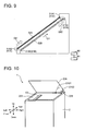
- FIG. 9 perspectively illustrates the first light guiding body 52A and the second light guiding body 52B of the illumination device 50 according to this embodiment.
- FIG. 10 perspectively illustrates a state where the document cover 22A is being closed in the image forming apparatus 1.
- FIG. 11 illustrates a procedure for light emission of the illumination device 50 in the image forming apparatus 1.
- the first light source 51A arranged on one end side in the first direction (the direction illustrated by the arrow D1 in FIG. 9 ) is defined as an eleventh light source 51A1 while the first light source 51A arranged on the other end side in the first direction is defined as a twelfth light source 51A2.
- the second light source 51 B arranged on one end side in the first direction is defined as a twenty-first light source 51B1 while the second light source 51 B arranged on the other end side in the first direction is defined as a twenty-second light source 51B2.
- the light emission of the eleventh light source 51A1, the twelfth light source 51A2, the twenty-first light source 51B1, and the twenty-second light source 51B2 are controlled by a control unit 80.
- the control unit 80 includes a central processing unit (CPU), a read only memory (ROM) that stores a control program, a random access memory (RAM) used as a work area of the CPU, and similar member.
- the control unit 80 executes the control program stored in the ROM by the CPU so as to function to control the light-emitting operation of the respective light sources described above.
- the control unit 80 controls the light-emitting operation of the plurality of light sources in the illumination device 50 corresponding to the reading mode of the image reading apparatus 22. This ensures irradiation of light to the original document at an appropriate luminescence level corresponding to the reading mode. Furthermore, this ensures reduction in electric power consumption in association with irradiation of light.
- Table 1 shows the relationship between the respective reading modes and the number (the number of LEDs to light) of light sources to emit light in the illumination device 50. In each reading mode, the image reading apparatus 22 reads the image of the document sheet corresponding to the image forming operation of the image forming apparatus 1. [Table 1] Reading Mode Number of Lighting LEDs Remarks Color 4 High Revolution 4 600 dpi or More Black and White 2 Low Resolution 2 300 dpi or Less
- the image reading apparatus 22 has a color mode (full-color reading mode), a black-and-white mode (single-color reading mode), a high-resolution reading mode, and a low-resolution reading mode. These reading modes are selected by the user through an operation unit 81 (see FIG. 9 ) included in the image forming apparatus 1, a personal computer connected to the image forming apparatus 1, or similar unit.
- the color mode is a mode in which the image of the document sheet is read as a full-color image of four colors.
- the imaging device 229 (see FIG. 1 ) photoelectrically converts the image of each color into an electrical signal. Accordingly, it is necessary to irradiate an intense light to the document sheet.
- the black-and-white mode is a mode in which the image of the document sheet is read as a black-and-white image (black image).
- the imaging device 229 photoelectrically converts a black-and-white image into an electrical signal. Accordingly, in the black-and-white mode, it is not necessary to irradiate an intense light to the document sheet compared with the color mode.
- the black-and-white mode is not limited to the mode in which the image of the document sheet is read as a single color image of black (Bk).
- the black-and-white mode may be a mode in which the image of the document sheet is read as single color images with each of the colors of yellow (Y), magenta (M), and cyan (C).
- the control unit 80 causes light emissions of all of the pair of the first light sources 51A and the pair of the second light sources 51 B. That is, in FIG. 9 , light emissions of all of the eleventh light source 51A1, the twelfth light source 51A2, the twenty-first light source 51B1, and the twenty-second light source 51 B2 are generated.
- the illuminating lights enter into the first light guiding body 52A and the second light guiding body 52B from both sides in the first direction (main-scanning direction), and then the illuminating lights are irradiated to the document sheet. Accordingly, the document sheet is irradiated with an intense light, thus ensuring stably reading the full-color image.
- the control unit 80 causes a light emission of the first light source 51A on one end side in the first direction among the pair of the first light sources 51A, and causes a light emission of the first light source 51A or the second light source 51 B on the other end side in the first direction.
- a light is emitted from the twelfth light source 51A2 on the one end side in the first direction among the first light sources 51A, and a light is emitted from the twenty-first light source 51B1 on the other end side in the first direction among the second light source 51 B.
- the illuminating light enters into the first light guiding body 52A from the one end side in the first direction (illustrated by an arrow D91 in FIG. 9 ). From the other end side in the first direction, an illuminating light enters into the second light guiding body 52B (illustrated by an arrow D92 in FIG. 9 ). From the first light guiding body 52A and the second light guiding body 52B, the illuminating lights are irradiated to the document sheet. Accordingly, a light that has a lower intensity than that of the illuminating light in the color mode and is sufficient and required for reading the single color image is irradiated to the document sheet so as to stably read the single color image. Excessive light irradiation for reading the single color image is restricted so as to reduce the power consumption of the illumination device 50 in association with the light irradiation.
- a light emission of the eleventh light source 51A1 may be generated instead of the twenty-first light source 51B1.
- the illuminating lights enter into the first light guiding body 52A from both sides in the first direction, and then the illuminating lights are irradiated to the document sheet.
- an illuminating light does not enter into the second light guiding body 52B. Accordingly, a light that has a lower intensity than that of the illuminating light in the color mode and is sufficient and required for reading the single color image is irradiated to the document sheet so as to stably read the single color image.
- Excessive light irradiation for reading the single color image is restricted so as to reduce the power consumption of the illumination device 50.
- the light emissions of the twelfth light source 51A2 on the one end side of the first light guiding body 52A and the twenty-first light source 51B1 on the other end side of the second light guiding body 52B are generated, the light uniformity in the first direction is maintained while the two light guiding bodies are used.
- the usage frequencies of the first light guiding body 52A and the second light guiding body 52B are equalized. This realizes prolonging of the illumination device 50.
- a high-resolution mode is a mode in which the image of the document sheet is read at a resolution equal to or more than 600 dpi (predetermined value). Accordingly, it is not necessary to irradiate an intense light to the document sheet.
- a low-resolution mode is a mode in which the image of the document sheet is read at a resolution equal to or less than 300 dpi (predetermined value). Accordingly, in the low-resolution mode, it is not necessary to irradiate an intense light to the document sheet compared with the high-resolution mode.
- the low-resolution mode may be a mode in which the image of the document sheet is read at a resolution less than 600 dpi (predetermined value).
- the control unit 80 causes light emissions of all the pair of the first light sources 51A and the pair of the second light sources 51 B similarly to the color mode.
- the illuminating lights enter into the first light guiding body 52A and the second light guiding body 52B from both sides in the first direction (main-scanning direction).
- the illuminating lights are irradiated to the document sheet. Accordingly, an intense light is irradiated to the document sheet. This ensures stably reading the image of the document sheet at a high resolution.
- the control unit 80 causes a light emission of the first light source 51A on the one end side in the first direction among the pair of the first light sources 51A and causes a light emission of the first light source 51A or the second light source 51B on the other end side in the first direction. That is, with reference to FIG. 9 , in the low-resolution mode, a light emission of the twelfth light source 51A2 on the one end side in the first direction among the first light sources 51A is generated, and a light emission of the twenty-first light source 51B1 on the other end side in the first direction among the second light sources 51 B.
- a light that has a lower intensity than that of the illuminating light in the high-resolution mode and is sufficient and required for the image in the low-resolution mode is irradiated to the document sheet so as to stably read the image of the document sheet. Additionally, excessive light irradiation in reading of the image in the low-resolution mode is restricted so as to reduce the power consumption of the illumination device 50.
- the image forming apparatus 1 includes a detection switch 22B in addition to the document cover 22A.
- the detection switch 22B is a switch that protrudes from the top surface portion of the housing 2 toward the upper side. As illustrated in FIG. 10 , when the document cover 22A is opened with respect to the housing 2 toward the upper side, the detection switch 22B is protruded toward the upper side by a biasing spring (not illustrated). At this time, the detection switch 22B is set to an off-state so as to output a LOW signal (0V signal) to the control unit 80. On the other hand, when the document cover 22A is turned downward from the state illustrated in FIG.
- the document cover 22A presses the detection switch 22B (in the direction illustrated by an arrow D102 in FIG. 10 ).
- the detection switch 22B is depressed into the housing 2.
- the control unit 80 outputs a HIGH signal (5V signal).
- the detection switch 22B is set to the off-state (in step #1 in FIG. 11 ). Subsequently, the document sheet is placed on the second contact glass 223 by the user (in step #2). Subsequently, when the document cover 22A is closed by the user, the detection switch 22B is set to the on-state (in step #3).
- the control unit 80 receives the HIGH signal from the detection switch 22B, the control unit 80 controls the illumination device 50 to perform an illumination operation for size detection on the document sheet (in step #4).
- the control unit 80 causes a light emission of the first light source 51A on the one end side in the first direction among the pair of the first light sources 51A, and causes a light emission of the first light source 51A or the second light source 51B on the other end side in the first direction. That is, similarly to the black-and-white mode, light emissions of the twelfth light source 51A2 and the twenty-first light source 51B1 in FIG. 9 are generated. Subsequently, the image reading apparatus 22 detects the size of the document sheet (in step #5).
- each light emission of one light source from both end sides in the first direction causes irradiation of the light that is required and sufficient for size detection on the document sheet to the document sheet. Accordingly, the size detection is stably performed. Accordingly, excessive light irradiation in the size detection for the document sheet is restricted so as to reduce the power consumption of the illumination device 50.
- step #5 in FIG. 11 after the size of the document sheet is detected, the copy operation of the image forming apparatus 1 is started (in step #6).
- the control unit 80 controls the illumination device 50 corresponding to the preliminarily set reading mode so as to cause light emissions of the first light source 51A and the second light source 51B for image reading on the document sheet (in step #7).
- the reading mode at this time may be any of the plurality of the reading modes.
- the image reading apparatus 22 reads the image of the document sheet. Subsequently, the image of the sheet is formed based on image data to be output from the image reading apparatus 22 (in step #8).
- the control unit 80 causes a light emission of the first light source 51A on the one end side in the first direction among the pair of the first light sources 51A and causes a light emission of the first light source 51A or the second light source 51 B on the other end side in the first direction so as to detect the size of the document sheet after the document sheet is placed on the second contact glass 223 before the image of the document sheet is read. Accordingly, the size of the document sheet can be detected while the electric power consumption is reduced in association with the light irradiation.
- This embodiment can cause the image reading apparatus 22 to irradiate the light to the document sheet at an appropriate luminescence level, and can reduce the electric power consumption in association with the light irradiation. As a result, the image is stably formed on the sheet based on the image data output from the image reading apparatus 22.
- the disclosure is not limited to this, and can employ, for example, the following modified embodiments.
- the image reading apparatus 22 may employ a configuration that has a high-speed reading mode and a low speed reading mode.
- the high-speed reading mode is a mode in which the image of the document sheet is read at a reading speed equal to or more than a predetermined value.
- the read speed of the document sheet in the high-speed reading mode corresponds to a printing speed equal to or more than 20 cpm (Copy per minutes) of the image forming apparatus 1 on which the image reading apparatus 22 is mounted.
- the high-speed reading mode is a mode in which the image reading apparatus 22 reads the images of 20 or more document sheets in A4 size per minute.
- the low speed reading mode is a mode in which the image of the document sheet is read at a reading speed less than the predetermined value.
- the read speed of the document sheet in the low speed reading mode corresponds to a printing speed less than 20 cpm in the image forming apparatus 1 in which the image reading apparatus 22 is mounted.
- the low speed reading mode is a mode in which the image reading apparatus 22 reads the images of less than 20 document sheets in A4 size per minute.
- the control unit 80 in the high-speed reading mode, causes light emissions of all the pair of the first light sources 51A and the pair of the second light sources 51 B similarly to the color mode.
- the illuminating lights after illuminating lights enter into the first light guiding body 52A and the second light guiding body 52B from both sides in the first direction (main-scanning direction), the illuminating lights are irradiated to the document sheet. Accordingly, an intense light is irradiated to the document sheet. This ensures stably reading the image of the document sheet in a short period.
- the control unit 80 cause a light emission of the first light source 51A on the one end side in the first direction among the pair of the first light sources 51A, and causes a light emission of the first light source 51A or the second light source 51 B on the other end side in the first direction. That is, with reference to FIG. 9 , in the low speed reading mode, a light emission of the twelfth light source 51A2 on the one end side in the first direction among the first light sources 51A is generated, and a light emission of the twenty-first light source 51B1 on the other end side in the first direction among the second light sources 51B is generated.
- a light that is that has a lower intensity than that of the illuminating light in the high-speed reading mode and is sufficient and required for reading the image in the low speed reading mode is irradiated to the document sheet so as to stably read the image of the document sheet. Additionally, excessive light irradiation in reading of the image in the low speed reading mode is restricted so as to reduce the power consumption of the illumination device 50.
Landscapes
- Engineering & Computer Science (AREA)
- Multimedia (AREA)
- Signal Processing (AREA)
- Facsimile Scanning Arrangements (AREA)
- Light Sources And Details Of Projection-Printing Devices (AREA)
- Optical Systems Of Projection Type Copiers (AREA)
- Image Input (AREA)
- Facsimile Heads (AREA)
Abstract
Description
- This application is based upon, and claims the benefit of priority from, corresponding Japanese Patent Application No.
2013-172099 - Unless otherwise indicated herein, the description in this section is not prior art to the claims in this application and is not admitted to be prior art by inclusion in this section.
- In an image reading apparatus such as a scanner and a copier, an illumination device is mounted. The illumination device irradiates a light to a document for optically reading the image of the document placed on a reading surface. Nowadays, as a light source for this illumination device, a light emitting diode (LED) is used. The LED has an advantage of high luminous efficiency. In this illumination device, it is necessary to illuminate the document in a line shape. However, since the LED is a point light source, a bar-shaped light guiding body and the LED are combined to generate a line-shaped illuminating light. The light guiding body includes an incident surface and a strip-shaped emission surface. The incident surface is arranged in an end portion of the light guiding body, and receives the illuminating light emitted from the LED. The emission surface extends along the longitudinal direction of the light guiding body, and causes emission of the illuminating light.
- There is a technique that includes one light guiding body and a reflective plate disposed to extend parallel to the light guiding body, in order to illuminate the document. The light guiding body includes two emission surfaces. The light emitted from one emission surface is directly irradiated to the document. The light emitted from the other emission surface is reflected at the reflective plate, and then irradiated to the document sheet. As a result, the lights from the two directions intersecting with each other are irradiated to the document.
- An image reading apparatus for reading an image of an original document according to the disclosure includes a document placement surface, an illumination unit, a light-receiving unit, and an illumination control unit. On the document placement surface, the original document is to be placed. The illumination unit is arranged to face the document placement surface. The illumination unit is configured to irradiate an illuminating light to the original document. The light-receiving unit is configured to receive a reflected light from the original document and convert the reflected light into an electrical signal. The illumination control unit is configured to control the illumination unit corresponding to a reading mode where the image of the original document is read. The illumination unit includes a first light guiding body in a bar shape, a second light guiding body, a pair of first light sources, and a pair of second light sources. The first light guiding body is in a bar shape extended in a first direction that includes: a pair of first incident surfaces arranged in both end portions of the first light guiding body in the first direction, the first incident surface being configured to receive a light injected along the first direction; and a first emission surface disposed to extend along the first direction, the first emission surface being configured to emit the light in a second direction intersecting with the first direction, the first light guiding body being configured to irradiate a light to the original document along the second direction. The second light guiding body is arranged at a distance from the first light guiding body, the second light guiding body being in a bar shape extended in the first direction, the second light guiding body including: a pair of second incident surfaces arranged in both end portions of the second light guiding body in the first direction, the second incident surface being configured to receive a light injected along the first direction; and a second emission surface disposed to extend along the first direction, the second emission surface being configured to emit the light in a third direction intersecting with the first direction, the second light guiding body being configured to irradiate a light to the original document along the third direction. The pair of first light sources is arranged to face the pair of the respective first incident surfaces of the first light guiding body to emit illuminating lights to be injected into the first incident surfaces. The pair of second light sources is arranged to face the pair of the respective second incident surfaces of the second light guiding body to emit illuminating lights to be injected into the second incident surface. The illumination control unit is configured to control light-emitting operations of the first light source and the second light source corresponding to the reading mode.
- These as well as other aspects, advantages, and alternatives will become apparent to those of ordinary skill in the art by reading the following detailed description with reference where appropriate to the accompanying drawings. Further, it should be understood that the description provided in this summary section and elsewhere in this document is intended to illustrate the claimed subject matter by way of example and not by way of limitation.
-
-
FIG. 1 illustrates schematic configurations of an image reading apparatus and an image forming apparatus according to one embodiment of the disclosure; -
FIG. 2 illustrates an illumination device according to the one embodiment; -
FIG. 3 illustrates the illumination device according to the one embodiment; -
FIG. 4 illustrates a light guiding body according to the one embodiment; -
FIG. 5 illustrates a cross section of the light guiding body according to the one embodiment; -
FIG. 6 illustrates a schematic cross section of the illumination device according to the one embodiment; -
FIG. 7 perspectively illustrates an exploded schematic view of the illumination device according to the one embodiment; -
FIG. 8 perspectively illustrates an exploded schematic view of the illumination device according to the one embodiment; -
FIG. 9 perspectively illustrates the light guiding body of the illumination device according to the one embodiment; -
FIG. 10 perspectively illustrates a schematic state where a document cover is being closed in the image forming apparatus according to the one embodiment; and -
FIG. 11 illustrates a procedure for light emission by the illumination device in the image forming apparatus according to the one embodiment. - Example apparatuses are described herein. Other example embodiments or features may further be utilized, and other changes may be made, without departing from the spirit or scope of the subject matter presented herein. In the following detailed description, reference is made to the accompanying drawings, which form a part thereof.
- The example embodiments described herein are not meant to be limiting. It will be readily understood that the aspects of the present disclosure, as generally described herein, and illustrated in the drawings, can be arranged, substituted, combined, separated, and designed in a wide variety of different configurations, all of which are explicitly contemplated herein.
- The following describes an embodiment of the disclosure in detail based on the drawings.
FIG. 1 illustrates the internal structure of animage forming apparatus 1 that includes animage reading apparatus 22 according to one embodiment of the disclosure. Here, as theimage forming apparatus 1, for example, what is called a copier of an in-barrel paper discharge type is illustrated. The apparatus to which theimage reading apparatus 22 according to the disclosure is applied is not limited to the copier, and may be, for example, a scanner apparatus, a facsimile apparatus, or a multi-functional peripheral. - The
image forming apparatus 1 includes ahousing 2. Thehousing 2 has a chassis structure in an approximately rectangular parallelepiped shape, and has an in-barrel space (in-barrel paper discharge unit 24). Thehousing 2 includes a lower chassis (apparatus main body 21), an upper chassis (image reading apparatus 22), and aconnection chassis 23. The lower chassis houses various devices for image formation. The upper chassis is arranged on the upper side of the apparatusmain body 21. Theconnection chassis 23 connects the apparatusmain body 21 and theimage reading apparatus 22 together. Theimage reading apparatus 22 optically reads the image of a document sheet (original document) to generate image data corresponding to the document image. The apparatusmain body 21 performs a process for forming a toner image on a sheet based on the image data. Between the apparatusmain body 21 and theimage reading apparatus 22, the in-barrelpaper discharge unit 24 is disposed. To the in-barrelpaper discharge unit 24, the sheet after the image formation is discharged. Theconnection chassis 23 is arranged on a side of the right side surface of thehousing 2, and includes adischarge port 961 for discharging a sheet to the in-barrelpaper discharge unit 24. - Inside of the apparatus
main body 21,toner containers intermediate transfer unit 92, animage forming unit 93, anexposure unit 94, and asheet feed cassette 211 are housed in this order from the left. - The
image forming unit 93 forms an image on a sheet based on the image data output from theimage reading apparatus 22. Theimage forming unit 93 includes fourimage formation units image formation units image formation units photoreceptor drum 11 and a charger 12, a developing device 13, aprimary transfer roller 14, and a cleaning device 15 arranged in the peripheral area of thisphotoreceptor drum 11. - The
photoreceptor drum 11 rotates around its own axis. On the circumference surface of thephotoreceptor drum 11, an electrostatic latent image and a toner image are formed. The charger 12 uniformly charges the surface of thephotoreceptor drum 11. The circumference surface of thephotoreceptor drum 11 after the charging is exposed by theexposure unit 94, and thus an electrostatic latent image is formed. - The developing device 13 supplies the toner to the circumference surface of the
photoreceptor drum 11 so as to develop the electrostatic latent image formed on thephotoreceptor drum 11. The developing device 13 includesagitation rollers 16 and 17, amagnetic roller 18, and a developingroller 19. Theagitation rollers 16 and 17 circulatively convey the two-component developer while agitating it, so as to charge the toner. On the circumference surface of themagnetic roller 18, a two-component developer layer is supported. On the circumference surface of the developingroller 19, a toner layer is supported. The toner layer is formed by delivery and receipt of the toner due to the difference in electric potential between themagnetic roller 18 and the developingroller 19. The toner on the developingroller 19 is supplied to the circumference surface of thephotoreceptor drum 11, so as to develop the electrostatic latent image. - The
primary transfer roller 14 sandwich anintermediate transfer belt 921 included in theintermediate transfer unit 92 so as to form a nip portion together with thephotoreceptor drum 11, and primarily transfers the toner image on thephotoreceptor drum 11 onto theintermediate transfer belt 921. The cleaning device 15 cleans the circumference surface of thephotoreceptor drum 11 after the transferring of the toner image. - The
yellow toner container 99Y, themagenta toner container 99M, thecyan toner container 99C, and the black toner container 99Bk reserve toners of respective colors. The toners of the respective colors are supplied through a supply path (not illustrated) to the developing devices 13 of theimage formation units - The
exposure unit 94 includes various kinds of optical system equipment, for example, a light source, a polygon mirror, a reflective mirror, and a deflecting mirror. Theexposure unit 94 irradiates the light based on the image data of the document image to the respective circumference surfaces of the photoreceptor drums 11 disposed in theimage formation units - The
intermediate transfer unit 92 includes anintermediate transfer belt 921, adrive roller 922, and a drivenroller 923. On theintermediate transfer belt 921, respective toner images from the plurality ofphotoreceptor drums 11 are superimposed (in primary transfer). The superimposed toner images are secondarily transferred to a sheet to be supplied from thesheet feed cassette 211 or asheet feed tray 30 in a secondary transfer unit 98. Thedrive roller 922 and the drivenroller 923 that circularly drive theintermediate transfer belt 921 are rotatably supported by the apparatusmain body 21. - The
sheet feed cassette 211 houses a sheet bundle formed by laminating a plurality of sheets. In the upper portion of thesheet feed cassette 211 on the right edge side, apickup roller 212 is arranged. Driving thepickup roller 212 feeds the sheet in the uppermost layer of the sheet bundle within thesheet feed cassette 211 one by one, so as to carry the fed sheet in a carry-inconveyance path 26. Here, on the right-side surface of the apparatusmain body 21, apaper feeding unit 40 is disposed. Thepaper feeding unit 40 includes thesheet feed tray 30 for manual paper feeding. The sheet placed on thesheet feed tray 30 is carried in the carry-inconveyance path 26 by the driving of apaper feed roller 41 of thepaper feeding unit 40. - At the downstream side of the carry-in
conveyance path 26, asheet conveyance path 28 is disposed. Thesheet conveyance path 28 is extended to thedischarge port 961 via the secondary transfer unit 98, a fixingunit 97, and asheet discharge unit 96, which are described later. The upstream portion of thesheet conveyance path 28 is formed between the inner wall formed in the apparatusmain body 21 and the inner wall forming the internal surface of a reverse conveying unit 29. Here, the outer surface of the reverse conveying unit 29 forms one surface of areverse conveyance path 291. In thereverse conveyance path 291, a sheet is inversely conveyed at the time of duplex printing. Further, at the upstream side of the secondary transfer unit 98 in thesheet conveyance path 28, aregistration roller pair 27 is arranged. The sheet is once stopped by theregistration roller pair 27 for skew correction. Subsequently, the sheet is sent out to the secondary transfer unit 98 at predetermined timing for image transfer. - The
connection chassis 23 houses the fixingunit 97 and thesheet discharge unit 96 inside. The fixingunit 97 includes a fixing roller and a pressure roller. In the secondary transfer unit 98, the fixingunit 97 heats and applies pressure to the sheet on which the toner image is secondarily transferred, so as to perform a fixing process. The sheet with the color image after the fixing process is discharged from thedischarge port 961 toward the in-barrelpaper discharge unit 24 by thesheet discharge unit 96. - The
image reading apparatus 22 includes afirst contact glass 222 and asecond contact glass 223. Thefirst contact glass 222 and thesecond contact glass 223 are fit into atop surface 221 of the upper chassis. When an automatic document feed (ADF, which is not illustrated) is arranged on theimage reading apparatus 22, thefirst contact glass 222 is disposed for reading a document sheet to be automatically fed from the ADF. On thesecond contact glass 223, a document sheet is placed by a user. Thesecond contact glass 223 is disposed for reading the placed document sheet. In this case, theimage reading apparatus 22 may include adocument cover 22A (seeFIG. 10 ) instead of the ADF. Above thesecond contact glass 223, thedocument cover 22A can be opened with respect to the top surface portion of theimage reading apparatus 22. When thedocument cover 22A is set to an open state, a document sheet is placed on thesecond contact glass 223 by the user. When thedocument cover 22A is set to a closed state, the document sheet is pressed and fixed by thedocument cover 22A. - The
image reading apparatus 22 includes a first movingcarriage 224, a second movingcarriage 225, a condensinglens unit 228, and an imaging device 229 (light-receiving unit), which are housed within the upper chassis. The first movingcarriage 224 includes anillumination device 50, which will be described later, and a firstreflective mirror 226. The second movingcarriage 225 includes a secondreflective mirror 227A and a thirdreflective mirror 227B for reversing the optical path. - The first moving
carriage 224 reciprocates in the right-left direction (sub-scanning direction) along the inferior surfaces of thefirst contact glass 222 and thesecond contact glass 223. The second movingcarriage 225 reciprocates by a movement amount that is a half of the movement amount of the first movingcarriage 224 in the right-left direction. In an automatic-feeding mode in which a document sheet is automatically fed from the automatic document feed (not illustrated), the first movingcarriage 224 moves to a position immediately below thefirst contact glass 222 and then is set to a resting state. In this resting state, a light is emitted from theillumination device 50 toward the document sheet. On the other hand, in a manual placement mode in which a document sheet is placed on thesecond contact glass 223, the first movingcarriage 224 moves from a position immediately below the left end of thesecond contact glass 223 toward the right side corresponding to the size of the document sheet. During this movement, a light is emitted from theillumination device 50 toward the document sheet. The second movingcarriage 225 moves to the right side by the movement amount that is a half of the movement amount of the first movingcarriage 224, following the first movingcarriage 224. - The
illumination device 50 irradiates an illuminating light in a line shape extended in the main-scanning direction (front-rear direction) to the document sheet (original document) as an irradiation target object. Theillumination device 50 is arranged to face thefirst contact glass 222 or thesecond contact glass 223. Specifically, theillumination device 50 emits the illuminating light to the document sheet that passes above thefirst contact glass 222 by automatic feeding or the document sheet that is placed on thesecond contact glass 223 by manual placement, for optically reading the document-sheet image. The firstreflective mirror 226 reflects the reflected light of the illuminating light that is emitted toward the document sheet by theillumination device 50 toward the secondreflective mirror 227A of the second movingcarriage 225. - The second
reflective mirror 227A reflects the reflected light that is reflected by the firstreflective mirror 226 toward the thirdreflective mirror 227B. The thirdreflective mirror 227B reflects the reflected light toward the condensinglens unit 228. The condensinglens unit 228 forms a light image of the reflected light that is reflected by the thirdreflective mirror 227B on the imaging surface of theimaging device 229. Theimaging device 229 is formed of a charge coupled device (CCD) and similar member, and receives the reflected light, and photoelectrically converts the received light into an analog electrical signal. This analog electrical signal is converted into a digital electrical signal by an A/D converter circuit (not illustrated). Subsequently, the digital electrical signal is input to the above-describedexposure unit 94 as the image data. - The following describes the detail of the
illumination device 50 according to the embodiment of the disclosure.FIG. 2 andFIG. 3 each perspectively illustrate theillumination device 50 on the first movingcarriage 224.FIG. 4 perspectively illustrates a firstlight guiding body 52A (or a secondlight guiding body 52B) of theillumination device 50.FIG. 5 illustrates a cross section of the firstlight guiding body 52A (or a secondlight guiding body 52B). Here, inFIG. 4 andFIG. 5 , the reference numerals for the secondlight guiding body 52B are illustrated in brackets. Further,FIG. 6 illustrates schematic cross sections of the respective light guiding bodies of theillumination device 50.FIG. 7 andFIG. 8 each perspectively illustrate an exploded schematic view of theillumination device 50. - The
illumination device 50 irradiates a light while setting a focal position to the document sheet (irradiation target object) arranged on thefirst contact glass 222 or the second contact glass 223 (predetermined arrangement surface). Theillumination device 50 is arranged on the first movingcarriage 224 along the main-scanning direction (the first direction illustrated by an arrow D1 inFIG. 2 andFIG. 3 ). - The
illumination device 50 includes a light source 51 (seeFIG. 7 ) and alight guiding body 52. Thelight guiding body 52 causes the propagation of the illuminating light emitted from thelight source 51 and converts this illuminating light into an illuminating light in a line shape, and then emits the converted illuminating light. Thelight source 51 includes a firstlight source 51A and a secondlight source 51B. Thelight guiding body 52 includes a firstlight guiding body 52A and a secondlight guiding body 52B. - The first
light guiding body 52A has a bar shape extended in the first direction. The firstlight guiding body 52A includes afirst incident surface 54A and afirst emission surface 56A (seeFIG. 4 ). Thefirst incident surface 54A is arranged in the end portion of the firstlight guiding body 52A in the first direction. Along the first direction, a light is injected into thefirst incident surface 54A. In this embodiment, a pair of the first incident surfaces 54A are arranged on both end portions of the firstlight guiding body 52A in the first direction. Thefirst emission surface 56A is disposed to extend along the first direction. Thefirst emission surface 56A emits the light in a second direction (illustrated by an arrow D2 inFIG. 4 andFIG. 6 ) intersecting with the first direction. Then, the firstlight guiding body 52A irradiates the light to the document sheet from the second direction. - The second
light guiding body 52B is arranged at a distance from the firstlight guiding body 52A. The secondlight guiding body 52B has a bar shape extended in the first direction. The secondlight guiding body 52B includes asecond incident surface 54B and asecond emission surface 56B. Thesecond incident surface 54B is arranged in the end portion of the secondlight guiding body 52B in the first direction. Along the first direction, a light is injected into thesecond incident surface 54B. In this embodiment, a pair of the second incident surfaces 54B are arranged on both end portions of the secondlight guiding body 52B in the first direction. Thesecond emission surface 56B is disposed to extend along the first direction. Thesecond emission surface 56B emits the light in a third direction (illustrated by an arrow D3 inFIG. 4 andFIG. 6 ), which will be described later, intersecting with the first direction. Then, the secondlight guiding body 52B irradiates the light to the document sheet from the third direction. - The light source 51 (the first
light source 51A and the secondlight source 51 B) has a thin circular plate shape, and includes a white light emitting diode (LED) 51 L, which emits a white-colored light (seeFIG. 4 ). - In this embodiment, the pair of the
first light sources 51A and the pair of the secondlight sources 51 B are respectively arranged in both the end portions of the firstlight guiding body 52A and both the end portions of the secondlight guiding body 52B. That is, the pair of thefirst light sources 51A are arranged to face the pair of the respective first incident surfaces 54A in the firstlight guiding body 52A. The pair of thefirst light sources 51A emit illuminating lights to be injected into the first incident surfaces 54A. The pair of the secondlight sources 51B are arranged to face the pair of the respective second incident surfaces 54B in the secondlight guiding body 52B. The pair of the secondlight sources 51 B emit illuminating lights to be injected into the second incident surfaces 54B. - Next, a description will be given of the structures of the first
light guiding body 52A and the secondlight guiding body 52B with reference toFIG. 4 andFIG. 5 . Here, in this embodiment, the secondlight guiding body 52B has a configuration similar to that of the firstlight guiding body 52A. The firstlight guiding body 52A and the secondlight guiding body 52B are different from each other in arrangement in theillumination device 50. Accordingly, inFIG. 4 andFIG. 5 , the structure of the firstlight guiding body 52A will be mainly described as an example. - The first
light guiding body 52A is formed of a translucent resin material such as acrylic resin. The firstlight guiding body 52A has a bar shape extended in the main-scanning direction (first direction), and includes amain unit 53 and the pair of the first incident surfaces 54A. Themain unit 53 guides illuminating lights emitted from thefirst light sources 51A. The pair of the first incident surfaces 54A are both of the end surfaces of themain unit 53 in the first direction, and the illuminating lights are injected into these first incident surfaces 54A. The above-described pair of thefirst light sources 51A have light-emitting surfaces arranged to face the pair of the respective first incident surfaces 54A. InFIG. 4 , the firstlight source 51A on the distal end side in the first direction is not illustrated in the drawing. - The first
light guiding body 52A further includes afirst emission surface 56A and a first reflectingsurface 57A. Thefirst emission surface 56A is arranged on the top surface side (on a side facing the first andsecond contact glasses 222 and 223) of themain unit 53. The first reflectingsurface 57A faces thisfirst emission surface 56A, and is arranged on the inferior surface side of themain unit 53. Thefirst emission surface 56A is a surface that extends along the main-scanning direction (first direction) on the top surface of themain unit 53, has a predetermined width in the direction perpendicular to the main-scanning direction, and emits the illuminating light toward the first andsecond contact glasses 222 and 223 (document sheet). The direction in which the illuminating light is emitted from thefirst emission surface 56A is defined as the second direction (illustrated by the arrow D2 inFIG. 4 to FIG. 6 ). The first reflectingsurface 57A is a strip-shaped surface that similarly extends in the main-scanning direction, and reflects the illuminating light propagating in themain unit 53 toward thefirst emission surface 56A. Thefirst emission surface 56A has a relatively shallow convex curved surface in the direction intersecting with the main-scanning direction. On the other hand, the first reflectingsurface 57A is a flat surface. The first reflectingsurface 57A has a large number of micro-prisms (not illustrated). The prism reflects a light toward thefirst emission surface 56A. - As described above, the second
light guiding body 52B also has a structure similar to that of the firstlight guiding body 52A. That is, the secondlight guiding body 52B also includes themain unit 53. Thefirst incident surface 54A, thefirst emission surface 56A, and the first reflectingsurface 57A of the firstlight guiding body 52A respectively correspond to thesecond incident surface 54B, thesecond emission surface 56B, a the second reflectingsurface 57B of the secondlight guiding body 52B. Here, the direction in which the illuminating light is emitted from thesecond emission surface 56B is defined as the third direction (illustrated by the arrow D3 inFIG. 4 to FIG. 6 ). Thus, the firstlight guiding body 52A and the secondlight guiding body 52B have the same shape and structure. Thus, the two light guiding bodies are commonalized. - Additionally, with reference to
FIG. 2 andFIG. 8 , theillumination device 50 includes afirst plate 60, asecond plate 61, and a heat dissipation unit 63 (seeFIG. 8 ). Thefirst plate 60 and thesecond plate 61 are plate-shaped members disposed upright from the first movingcarriage 224 toward the upper side. Thefirst plate 60 supports the firstlight guiding body 52A and the secondlight guiding body 52B in the first direction on one end side. Thesecond plate 61 supports the firstlight guiding body 52A and the secondlight guiding body 52B in the first direction on the other end side. - With reference to
FIG. 7 andFIG. 8 , thefirst plate 60 includes aneleventh plate 60A and atwelfth plate 60B. Theeleventh plate 60A and thetwelfth plate 60B are plate-shaped members arranged to face each other. Theeleventh plate 60A supports the firstlight source 51A and the secondlight source 51B. Thetwelfth plate 60B supports the firstlight guiding body 52A and the secondlight guiding body 52B. Furthermore, thetwelfth plate 60B faces the firstlight source 51A and the secondlight source 51 B, and exposes thefirst incident surface 54A and thesecond incident surface 54B (seeFIG. 4 ). Specifically, thetwelfth plate 60B includes a first opening portion 60B1 and a second opening portion 60B2. The respective one end sides of the firstlight guiding body 52A and the secondlight guiding body 52B are inserted into the first opening portion 60B1 and the second opening portion 60B2. As a result, thefirst incident surface 54A and thesecond incident surface 54B are exposed with respect to theeleventh plate 60A side. Mounting theeleventh plate 60A with thetwelfth plate 60B causes arrangement in which the firstlight source 51A and the secondlight source 51B are arranged to respectively face thefirst incident surface 54A and thesecond incident surface 54B. Here, thesecond plate 61 has a configuration similar to that of thefirst plate 60. - The heat dissipation unit 63 (see
FIG. 8 ) is arranged in contact with theeleventh plate 60A. Theheat dissipation unit 63 includes aheat dissipation rib 63T. Theheat dissipation rib 63T increases the surface area of theheat dissipation unit 63. Accordingly, theheat dissipation unit 63 functions as a heat sink. When theheat dissipation unit 63 is mounted on thefirst plate 60, the heat generated in association with light emission of the firstlight source 51A and the secondlight source 51B transfers from theeleventh plate 60A to theheat dissipation unit 63. Then, the heat is discharged from theheat dissipation rib 63T to the outside of theillumination device 50. - Next, a description will be given of the direction of the irradiation light according to this embodiment with reference to
FIG. 6 . The firstlight guiding body 52A and the secondlight guiding body 52B are arranged to be inclined by a predetermined angle, so as to have respective emission surfaces facing each other. As described above, the firstlight guiding body 52A irradiates the light of the firstlight source 51A to a document sheet P from the second direction. The secondlight guiding body 52B irradiates the light of the secondlight source 51 B to the document sheet P from the third direction. That is, in the cross section intersecting with the first direction illustrated inFIG. 6 , the second direction is the direction from one document placement surface side toward the document sheet P with respect to the normal line RL perpendicular to thefirst contact glass 222 or the second contact glass 223 (document placement surface). The third direction is the direction from another document placement surface side toward the document sheet P with respect to the normal line RL. This ensures stable irradiation of the light to the document sheet P from both sides of the normal line RL. Further, in this embodiment, in the cross section, a triangular shape TR connecting the firstlight guiding body 52A, the secondlight guiding body 52B, and a focal point SP of the irradiation light is an isosceles triangle in which the focal point SP is the vertex. Accordingly, respective distributions of the lights to be irradiated to the document sheet P from the firstlight guiding body 52A and the secondlight guiding body 52B are line-symmetric with respect to each other in the cross section intersecting with the first direction. Accordingly, even when the respective lights to be irradiated from the firstlight guiding body 52A and the secondlight guiding body 52B overlap each other, a uniform light can be irradiated to the document sheet P. In other words, it is restricted that reduction of the luminescence level on one document sheet P side with reference to the normal line RL more than the luminescence level on another document sheet P side. Here, in another embodiment, the triangular shape TR connecting the firstlight guiding body 52A, the secondlight guiding body 52B, and the focal point SP of the irradiation light may be an equilateral triangle. - In the above-described configuration, the first direction is the main-scanning direction of the
image reading apparatus 22. In the cross section intersecting with the first direction, the direction (illustrated by an arrow D4 inFIG. 6 ) from the firstlight guiding body 52A toward the secondlight guiding body 52B is the sub-scanning direction. The document sheet P as the irradiation target object is irradiated with lights from the two light guiding bodies (the firstlight guiding body 52A and the secondlight guiding body 52B). In each of the two light guiding bodies, two light sources (the firstlight source 51A and the secondlight source 51 B) are arranged. Accordingly, the document sheet P can be irradiated with lights from the two different directions. This ensures irradiation of light to the document sheet P at a higher luminescence level compared with the case where the light is irradiated from one light guiding body. Additionally, the luminescence amount of one light source is allowed to be small. This ensures reduction in heat amount generated by each light source. Accordingly, this reduces thermal distortion of thelight source 51, thelight guiding body 52, and the peripheral member due to the heat. Theillumination device 50 can reciprocate in the sub-scanning direction. This causes stably reading the image of the document sheet P that expands in the main-scanning direction and the sub-scanning direction. - Next, in the
image forming apparatus 1 according to this embodiment, a description will be given of a configuration in which theillumination device 50 is used.FIG. 9 perspectively illustrates the firstlight guiding body 52A and the secondlight guiding body 52B of theillumination device 50 according to this embodiment.FIG. 10 perspectively illustrates a state where thedocument cover 22A is being closed in theimage forming apparatus 1.FIG. 11 illustrates a procedure for light emission of theillumination device 50 in theimage forming apparatus 1. - With reference to
FIG. 9 , among the above-described firstlight sources 51A, the firstlight source 51A arranged on one end side in the first direction (the direction illustrated by the arrow D1 inFIG. 9 ) is defined as an eleventh light source 51A1 while the firstlight source 51A arranged on the other end side in the first direction is defined as a twelfth light source 51A2. Similarly, among the secondlight sources 51 B, the secondlight source 51 B arranged on one end side in the first direction is defined as a twenty-first light source 51B1 while the secondlight source 51 B arranged on the other end side in the first direction is defined as a twenty-second light source 51B2. The light emission of the eleventh light source 51A1, the twelfth light source 51A2, the twenty-first light source 51B1, and the twenty-second light source 51B2 are controlled by acontrol unit 80. - The
control unit 80 includes a central processing unit (CPU), a read only memory (ROM) that stores a control program, a random access memory (RAM) used as a work area of the CPU, and similar member. Thecontrol unit 80 executes the control program stored in the ROM by the CPU so as to function to control the light-emitting operation of the respective light sources described above. - In this embodiment, the
control unit 80 controls the light-emitting operation of the plurality of light sources in theillumination device 50 corresponding to the reading mode of theimage reading apparatus 22. This ensures irradiation of light to the original document at an appropriate luminescence level corresponding to the reading mode. Furthermore, this ensures reduction in electric power consumption in association with irradiation of light. Table 1 shows the relationship between the respective reading modes and the number (the number of LEDs to light) of light sources to emit light in theillumination device 50. In each reading mode, theimage reading apparatus 22 reads the image of the document sheet corresponding to the image forming operation of theimage forming apparatus 1.[Table 1] Reading Mode Number of Lighting LEDs Remarks Color 4 High Revolution 4 600 dpi or More Black and White 2 Low Resolution 2 300 dpi or Less - In this embodiment, the
image reading apparatus 22 has a color mode (full-color reading mode), a black-and-white mode (single-color reading mode), a high-resolution reading mode, and a low-resolution reading mode. These reading modes are selected by the user through an operation unit 81 (seeFIG. 9 ) included in theimage forming apparatus 1, a personal computer connected to theimage forming apparatus 1, or similar unit. - The color mode is a mode in which the image of the document sheet is read as a full-color image of four colors. In the color mode, the imaging device 229 (see
FIG. 1 ) photoelectrically converts the image of each color into an electrical signal. Accordingly, it is necessary to irradiate an intense light to the document sheet. On the other hand, the black-and-white mode is a mode in which the image of the document sheet is read as a black-and-white image (black image). In the black-and-white mode, theimaging device 229 photoelectrically converts a black-and-white image into an electrical signal. Accordingly, in the black-and-white mode, it is not necessary to irradiate an intense light to the document sheet compared with the color mode. Here, the black-and-white mode is not limited to the mode in which the image of the document sheet is read as a single color image of black (Bk). In another embodiment, the black-and-white mode may be a mode in which the image of the document sheet is read as single color images with each of the colors of yellow (Y), magenta (M), and cyan (C). - In this embodiment, in the color mode, the control unit 80 (see
FIG. 9 ) causes light emissions of all of the pair of thefirst light sources 51A and the pair of the secondlight sources 51 B. That is, inFIG. 9 , light emissions of all of the eleventh light source 51A1, the twelfth light source 51A2, the twenty-first light source 51B1, and the twenty-secondlight source 51 B2 are generated. As a result, the illuminating lights enter into the firstlight guiding body 52A and the secondlight guiding body 52B from both sides in the first direction (main-scanning direction), and then the illuminating lights are irradiated to the document sheet. Accordingly, the document sheet is irradiated with an intense light, thus ensuring stably reading the full-color image. - On the other hand, in the black-and-white mode, the
control unit 80 causes a light emission of the firstlight source 51A on one end side in the first direction among the pair of thefirst light sources 51A, and causes a light emission of the firstlight source 51A or the secondlight source 51 B on the other end side in the first direction. As one example, with reference toFIG. 9 , in the black-and-white mode, a light is emitted from the twelfth light source 51A2 on the one end side in the first direction among thefirst light sources 51A, and a light is emitted from the twenty-first light source 51B1 on the other end side in the first direction among the secondlight source 51 B. As a result, the illuminating light enters into the firstlight guiding body 52A from the one end side in the first direction (illustrated by an arrow D91 inFIG. 9 ). From the other end side in the first direction, an illuminating light enters into the secondlight guiding body 52B (illustrated by an arrow D92 inFIG. 9 ). From the firstlight guiding body 52A and the secondlight guiding body 52B, the illuminating lights are irradiated to the document sheet. Accordingly, a light that has a lower intensity than that of the illuminating light in the color mode and is sufficient and required for reading the single color image is irradiated to the document sheet so as to stably read the single color image. Excessive light irradiation for reading the single color image is restricted so as to reduce the power consumption of theillumination device 50 in association with the light irradiation. - Here, in another embodiment, in the black-and-white mode, a light emission of the eleventh light source 51A1 may be generated instead of the twenty-first light source 51B1. Also in this case, the illuminating lights enter into the first
light guiding body 52A from both sides in the first direction, and then the illuminating lights are irradiated to the document sheet. Here, in this case, an illuminating light does not enter into the secondlight guiding body 52B. Accordingly, a light that has a lower intensity than that of the illuminating light in the color mode and is sufficient and required for reading the single color image is irradiated to the document sheet so as to stably read the single color image. Excessive light irradiation for reading the single color image is restricted so as to reduce the power consumption of theillumination device 50. Here, as described above, when the light emissions of the twelfth light source 51A2 on the one end side of the firstlight guiding body 52A and the twenty-first light source 51B1 on the other end side of the secondlight guiding body 52B are generated, the light uniformity in the first direction is maintained while the two light guiding bodies are used. The usage frequencies of the firstlight guiding body 52A and the secondlight guiding body 52B are equalized. This realizes prolonging of theillumination device 50. - Further, with reference to Table 1, a high-resolution mode is a mode in which the image of the document sheet is read at a resolution equal to or more than 600 dpi (predetermined value). Accordingly, it is not necessary to irradiate an intense light to the document sheet. On the other hand, a low-resolution mode is a mode in which the image of the document sheet is read at a resolution equal to or less than 300 dpi (predetermined value). Accordingly, in the low-resolution mode, it is not necessary to irradiate an intense light to the document sheet compared with the high-resolution mode. Here, the low-resolution mode may be a mode in which the image of the document sheet is read at a resolution less than 600 dpi (predetermined value).
- In this embodiment, in the high-resolution mode, the control unit 80 (see
FIG. 9 ) causes light emissions of all the pair of thefirst light sources 51A and the pair of the secondlight sources 51 B similarly to the color mode. As a result, the illuminating lights enter into the firstlight guiding body 52A and the secondlight guiding body 52B from both sides in the first direction (main-scanning direction). Subsequently, the illuminating lights are irradiated to the document sheet. Accordingly, an intense light is irradiated to the document sheet. This ensures stably reading the image of the document sheet at a high resolution. - On the other hand, in the low-resolution mode, similarly to the black-and-white mode, the
control unit 80 causes a light emission of the firstlight source 51A on the one end side in the first direction among the pair of thefirst light sources 51A and causes a light emission of the firstlight source 51A or the secondlight source 51B on the other end side in the first direction. That is, with reference toFIG. 9 , in the low-resolution mode, a light emission of the twelfth light source 51A2 on the one end side in the first direction among thefirst light sources 51A is generated, and a light emission of the twenty-first light source 51B1 on the other end side in the first direction among the secondlight sources 51 B. Accordingly, a light that has a lower intensity than that of the illuminating light in the high-resolution mode and is sufficient and required for the image in the low-resolution mode is irradiated to the document sheet so as to stably read the image of the document sheet. Additionally, excessive light irradiation in reading of the image in the low-resolution mode is restricted so as to reduce the power consumption of theillumination device 50. - Further, in this embodiment, before the image of the document sheet is read, size detection for the document sheet is performed. With reference to
FIG. 10 , theimage forming apparatus 1 includes adetection switch 22B in addition to thedocument cover 22A. Thedetection switch 22B is a switch that protrudes from the top surface portion of thehousing 2 toward the upper side. As illustrated inFIG. 10 , when thedocument cover 22A is opened with respect to thehousing 2 toward the upper side, thedetection switch 22B is protruded toward the upper side by a biasing spring (not illustrated). At this time, thedetection switch 22B is set to an off-state so as to output a LOW signal (0V signal) to thecontrol unit 80. On the other hand, when thedocument cover 22A is turned downward from the state illustrated inFIG. 10 (in the direction illustrated by an arrow D101 inFIG. 10 ) so as to be closed with respect to thehousing 2, thedocument cover 22A presses thedetection switch 22B (in the direction illustrated by an arrow D102 inFIG. 10 ). As a result, thedetection switch 22B is depressed into thehousing 2. At this time, thedetection switch 22B is set to an on-state, and thecontrol unit 80 outputs a HIGH signal (5V signal). - With reference to
FIG. 11 , when thedocument cover 22A is opened by the user, thedetection switch 22B is set to the off-state (instep # 1 inFIG. 11 ). Subsequently, the document sheet is placed on thesecond contact glass 223 by the user (in step #2). Subsequently, when thedocument cover 22A is closed by the user, thedetection switch 22B is set to the on-state (in step #3). When thecontrol unit 80 receives the HIGH signal from thedetection switch 22B, thecontrol unit 80 controls theillumination device 50 to perform an illumination operation for size detection on the document sheet (in step #4). - In this embodiment, in the illumination operation for size detection on the document sheet, the
control unit 80 causes a light emission of the firstlight source 51A on the one end side in the first direction among the pair of thefirst light sources 51A, and causes a light emission of the firstlight source 51A or the secondlight source 51B on the other end side in the first direction. That is, similarly to the black-and-white mode, light emissions of the twelfth light source 51A2 and the twenty-first light source 51B1 inFIG. 9 are generated. Subsequently, theimage reading apparatus 22 detects the size of the document sheet (in step #5). - In the size detection on the document sheet, it is only necessary to irradiate light to both end portions in the main-scanning direction (first direction) of the document sheet so as to detect the positions of both the end portions of the document sheet. Accordingly, it is not necessary to irradiate an intense light like the light in the color mode to the document sheet. Accordingly, as described above, each light emission of one light source from both end sides in the first direction causes irradiation of the light that is required and sufficient for size detection on the document sheet to the document sheet. Accordingly, the size detection is stably performed. Accordingly, excessive light irradiation in the size detection for the document sheet is restricted so as to reduce the power consumption of the
illumination device 50. - In
step # 5 inFIG. 11 , after the size of the document sheet is detected, the copy operation of theimage forming apparatus 1 is started (in step #6). Thecontrol unit 80 controls theillumination device 50 corresponding to the preliminarily set reading mode so as to cause light emissions of the firstlight source 51A and the secondlight source 51B for image reading on the document sheet (in step #7). The reading mode at this time may be any of the plurality of the reading modes. Theimage reading apparatus 22 reads the image of the document sheet. Subsequently, the image of the sheet is formed based on image data to be output from the image reading apparatus 22 (in step #8). - Thus, in this embodiment, the
control unit 80 causes a light emission of the firstlight source 51A on the one end side in the first direction among the pair of thefirst light sources 51A and causes a light emission of the firstlight source 51A or the secondlight source 51 B on the other end side in the first direction so as to detect the size of the document sheet after the document sheet is placed on thesecond contact glass 223 before the image of the document sheet is read. Accordingly, the size of the document sheet can be detected while the electric power consumption is reduced in association with the light irradiation. - Preferred embodiments of the disclosure have been described above. This embodiment can cause the
image reading apparatus 22 to irradiate the light to the document sheet at an appropriate luminescence level, and can reduce the electric power consumption in association with the light irradiation. As a result, the image is stably formed on the sheet based on the image data output from theimage reading apparatus 22. Here, the disclosure is not limited to this, and can employ, for example, the following modified embodiments. - While in the above-described embodiment the case where the
image reading apparatus 22 has four reading modes of the color mode, the black-and-white mode, the high-resolution mode, and the low-resolution mode has been described, the disclosure is not limited to this. Theimage reading apparatus 22 may employ a configuration that has a high-speed reading mode and a low speed reading mode. The high-speed reading mode is a mode in which the image of the document sheet is read at a reading speed equal to or more than a predetermined value. In this embodiment, the read speed of the document sheet in the high-speed reading mode corresponds to a printing speed equal to or more than 20 cpm (Copy per minutes) of theimage forming apparatus 1 on which theimage reading apparatus 22 is mounted. In other words, the high-speed reading mode is a mode in which theimage reading apparatus 22 reads the images of 20 or more document sheets in A4 size per minute. On the other hand, the low speed reading mode is a mode in which the image of the document sheet is read at a reading speed less than the predetermined value. In this embodiment, the read speed of the document sheet in the low speed reading mode corresponds to a printing speed less than 20 cpm in theimage forming apparatus 1 in which theimage reading apparatus 22 is mounted. In other words, the low speed reading mode is a mode in which theimage reading apparatus 22 reads the images of less than 20 document sheets in A4 size per minute. - In this modified embodiment, in the high-speed reading mode, the control unit 80 (see
FIG. 9 ) causes light emissions of all the pair of thefirst light sources 51A and the pair of the secondlight sources 51 B similarly to the color mode. As a result, after illuminating lights enter into the firstlight guiding body 52A and the secondlight guiding body 52B from both sides in the first direction (main-scanning direction), the illuminating lights are irradiated to the document sheet. Accordingly, an intense light is irradiated to the document sheet. This ensures stably reading the image of the document sheet in a short period. - On the other hand, in the low speed reading mode, similarly to the black-and-white mode, the
control unit 80 cause a light emission of the firstlight source 51A on the one end side in the first direction among the pair of thefirst light sources 51A, and causes a light emission of the firstlight source 51A or the secondlight source 51 B on the other end side in the first direction. That is, with reference toFIG. 9 , in the low speed reading mode, a light emission of the twelfth light source 51A2 on the one end side in the first direction among thefirst light sources 51A is generated, and a light emission of the twenty-first light source 51B1 on the other end side in the first direction among the secondlight sources 51B is generated. Accordingly, a light that is that has a lower intensity than that of the illuminating light in the high-speed reading mode and is sufficient and required for reading the image in the low speed reading mode is irradiated to the document sheet so as to stably read the image of the document sheet. Additionally, excessive light irradiation in reading of the image in the low speed reading mode is restricted so as to reduce the power consumption of theillumination device 50. - While various aspects and embodiments have been disclosed herein, other aspects and embodiments will be apparent to those skilled in the art. The various aspects and embodiments disclosed herein are for purposes of illustration and are not intended to be limiting, with the true scope and spirit being indicated by the following claims.
Claims (9)
- An image reading apparatus for reading an image of an original document, comprising:a document placement surface on which the original document is to be placed;an illumination unit arranged to face the document placement surface, the illumination unit being configured to irradiate an illuminating light to the original document;a light-receiving unit configured to receive a reflected light from the original document and convert the reflected light into an electrical signal; andan illumination control unit configured to control the illumination unit corresponding to a reading mode where the image of the original document is read,wherein the illumination unit includes:a first light guiding body in a bar shape extended in a first direction that includes: a pair of first incident surfaces arranged in both end portions of the first light guiding body in the first direction, the first incident surface being configured to receive a light injected along the first direction; and a first emission surface disposed to extend along the first direction, the first emission surface being configured to emit the light in a second direction intersecting with the first direction, the first light guiding body being configured to irradiate a light to the original document along the second direction;a second light guiding body arranged at a distance from the first light guiding body, the second light guiding body being in a bar shape extended in the first direction, the second light guiding body including: a pair of second incident surfaces arranged in both end portions of the second light guiding body in the first direction, the second incident surface being configured to receive a light injected along the first direction; and a second emission surface disposed to extend along the first direction, the second emission surface being configured to emit the light in a third direction intersecting with the first direction, the second light guiding body being configured to irradiate a light to the original document along the third direction;a pair of first light sources arranged to face the pair of the respective first incident surfaces of the first light guiding body to emit illuminating lights to be injected into the first incident surfaces; anda pair of second light sources arranged to face the pair of the respective second incident surfaces of the second light guiding body to emit illuminating lights to be injected into the second incident surface,wherein the illumination control unit is configured to control light-emitting operations of the first light source and the second light source corresponding to the reading mode.
- The image reading apparatus according to claim 1,
wherein the illumination control unit is configured to:cause light emissions of all the pair of first light sources and the pair of second light sources in a full-color reading mode where the image of the original document is read as a full-color image; andcause a light emission of the first light source on one end side in the first direction among the pair of first light sources and cause a light emission of the first light source or the second light source on another end side in the first direction in a single-color reading mode where the image of the original document is read as a single color image. - The image reading apparatus according to claim 1,
wherein the illumination control unit is configured to:cause light emissions of all the pair of first light sources and the pair of second light sources in a high-resolution reading mode where the image of the original document is read at a resolution equal to or more than a predetermined value; andcause a light emission of the first light source on one end side in the first direction among the pair of first light sources and cause a light emission of the first light source or the second light source on another end side in the first direction in a low-resolution reading mode where the image of the original document is read at a resolution less than the predetermined value. - The image reading apparatus according to claim 1,
wherein the illumination control unit is configured to:cause light emissions of all the pair of first light sources and the pair of second light sources in a high-speed reading mode where the image of the original document is read at a reading speed equal to or more than a predetermined value; andcause a light emission of the first light source on one end side in the first direction among the pair of first light sources and cause a light emission of the first light source or the second light source on another end side in the first direction in a low speed reading mode where the image of the original document is read at a reading speed less than predetermined value. - The image reading apparatus according to claim 1,
wherein the illumination control unit is configured to cause a light emission of the first light source on the one end side in the first direction among the pair of first light sources and cause a light emission of one of the first light source or the second light source and the other end side in the first direction so as to detect a size of the original document after the original document is placed on the document placement surface before the image of the original document is read. - The image reading apparatus according to claim 1,
wherein in a cross section intersecting with the first direction,
the second direction is a direction from one document placement surface side with respect to a normal line perpendicular to the document placement surface toward the original document, and
the third direction is a direction from another document placement surface side with respect to the normal line toward the original document. - The image reading apparatus according to claim 6,
wherein the original document is to be arranged at a focal position of lights to be emitted from the first light guiding body and the second light guiding body, and
in the cross section, a triangular shape connecting the first light guiding body, the second light guiding body, and the focal point is an isosceles triangle where the focal point is a vertex. - The image reading apparatus according to claim 1,
wherein the first direction is a main-scanning direction while a direction from the first light guiding body toward the second light guiding body in a cross section intersecting with the first direction is a sub-scanning direction, and
the illumination unit is movable in the sub-scanning direction. - An image forming apparatus, comprising:the image reading apparatus according to claim 1; andan image forming unit configured to form an image on a sheet based on image data to be output from the image reading apparatus.
Applications Claiming Priority (1)
| Application Number | Priority Date | Filing Date | Title |
|---|---|---|---|
| JP2013172099A JP5860854B2 (en) | 2013-08-22 | 2013-08-22 | Image reading apparatus and image forming apparatus having the same |
Publications (3)
| Publication Number | Publication Date |
|---|---|
| EP2840768A2 true EP2840768A2 (en) | 2015-02-25 |
| EP2840768A3 EP2840768A3 (en) | 2015-03-04 |
| EP2840768B1 EP2840768B1 (en) | 2018-11-21 |
Family
ID=51429035
Family Applications (1)
| Application Number | Title | Priority Date | Filing Date |
|---|---|---|---|
| EP14181734.6A Not-in-force EP2840768B1 (en) | 2013-08-22 | 2014-08-21 | Image reading apparatus efficiently illuminating light |
Country Status (4)
| Country | Link |
|---|---|
| US (1) | US9083841B2 (en) |
| EP (1) | EP2840768B1 (en) |
| JP (1) | JP5860854B2 (en) |
| CN (1) | CN104427189B (en) |
Cited By (1)
| Publication number | Priority date | Publication date | Assignee | Title |
|---|---|---|---|---|
| EP3637750A1 (en) * | 2018-10-11 | 2020-04-15 | Ricoh Company, Ltd. | Document size detection device, image reading device, image forming apparatus, document size detecting method, and carrier means |
Families Citing this family (3)
| Publication number | Priority date | Publication date | Assignee | Title |
|---|---|---|---|---|
| JP6222473B2 (en) * | 2014-08-29 | 2017-11-01 | 京セラドキュメントソリューションズ株式会社 | Image reading apparatus and image forming apparatus provided with the image reading apparatus |
| JP6992324B2 (en) | 2017-08-25 | 2022-01-13 | 京セラドキュメントソリューションズ株式会社 | An image forming apparatus equipped with an image reading device and an image reading device. |
| JP7654375B2 (en) * | 2020-10-06 | 2025-04-01 | キヤノン株式会社 | IMAGE PROCESSING APPARATUS, CONTROL METHOD FOR IMAGE PROCESSING APPARATUS, AND PROGRAM |
Family Cites Families (14)
| Publication number | Priority date | Publication date | Assignee | Title |
|---|---|---|---|---|
| JPH06311307A (en) * | 1993-04-22 | 1994-11-04 | Minolta Camera Co Ltd | Image forming device |
| JP3423572B2 (en) * | 1996-06-06 | 2003-07-07 | キヤノン株式会社 | Image reading system, its control device, image reading method, and storage medium |
| JP2004343355A (en) * | 2003-05-14 | 2004-12-02 | Minolta Co Ltd | Image reader |
| JP4412070B2 (en) * | 2004-06-24 | 2010-02-10 | 富士ゼロックス株式会社 | Image reading apparatus and image data correction method |
| JP2007060613A (en) * | 2005-07-29 | 2007-03-08 | Ricoh Co Ltd | Image reading device |
| JP4793288B2 (en) | 2007-03-01 | 2011-10-12 | ウシオ電機株式会社 | Light guide and bifurcated linear light source device |
| JP4798175B2 (en) * | 2008-05-30 | 2011-10-19 | ブラザー工業株式会社 | Image reading apparatus and program |
| JP5185100B2 (en) * | 2008-12-22 | 2013-04-17 | キヤノン株式会社 | Image reading apparatus, multifunction printer apparatus, and image reading method |
| JP5418034B2 (en) * | 2009-07-17 | 2014-02-19 | 富士ゼロックス株式会社 | Image reading apparatus, image forming apparatus, and program |
| JP5573107B2 (en) * | 2009-11-04 | 2014-08-20 | ウシオ電機株式会社 | Lighting device |
| EP2672690B1 (en) * | 2011-01-31 | 2019-03-27 | Canon Finetech Nisca Inc. | Illumination device |
| JP5837767B2 (en) * | 2011-06-20 | 2015-12-24 | ニスカ株式会社 | Light source unit |
| KR101883315B1 (en) * | 2011-11-18 | 2018-08-01 | 에이치피프린팅코리아 주식회사 | Image scanning apparatus and control method thereof |
| JP5418634B2 (en) * | 2012-05-29 | 2014-02-19 | 三菱電機株式会社 | Contact image sensor and illumination optical system |
-
2013
- 2013-08-22 JP JP2013172099A patent/JP5860854B2/en not_active Expired - Fee Related
-
2014
- 2014-07-30 CN CN201410370552.1A patent/CN104427189B/en not_active Expired - Fee Related
- 2014-08-21 EP EP14181734.6A patent/EP2840768B1/en not_active Not-in-force
- 2014-08-22 US US14/465,857 patent/US9083841B2/en not_active Expired - Fee Related
Non-Patent Citations (1)
| Title |
|---|
| None |
Cited By (3)
| Publication number | Priority date | Publication date | Assignee | Title |
|---|---|---|---|---|
| EP3637750A1 (en) * | 2018-10-11 | 2020-04-15 | Ricoh Company, Ltd. | Document size detection device, image reading device, image forming apparatus, document size detecting method, and carrier means |
| CN111050018A (en) * | 2018-10-11 | 2020-04-21 | 株式会社理光 | Document size detection apparatus, document size detection method, image reading apparatus, and image forming apparatus |
| US11095788B2 (en) | 2018-10-11 | 2021-08-17 | Ricoh Company, Ltd. | Document size detection device, image reading device, image forming apparatus, document size detecting method, and recording medium |
Also Published As
| Publication number | Publication date |
|---|---|
| US20150055196A1 (en) | 2015-02-26 |
| JP2015041895A (en) | 2015-03-02 |
| CN104427189B (en) | 2018-07-17 |
| CN104427189A (en) | 2015-03-18 |
| EP2840768A3 (en) | 2015-03-04 |
| US9083841B2 (en) | 2015-07-14 |
| JP5860854B2 (en) | 2016-02-16 |
| EP2840768B1 (en) | 2018-11-21 |
Similar Documents
| Publication | Publication Date | Title |
|---|---|---|
| CN102598647B (en) | Illumination device, image reading device having the same, image forming device having the image reading device | |
| JP2013157841A (en) | Light guide, illuminating device, and image reading apparatus and image forming apparatus including the same | |
| EP2840768B1 (en) | Image reading apparatus efficiently illuminating light | |
| US20190191050A1 (en) | Illumination device, image scanning apparatus, and image forming apparatus | |
| CN104079766B (en) | Illumination device, image reading apparatus, and image forming apparatus | |
| CN108459410B (en) | Optical scanning device and image forming device | |
| JP6140790B2 (en) | Image reading apparatus and image forming apparatus having the same | |
| CN102292971B (en) | Lighting device, image reader, and image forming device | |
| JP5879293B2 (en) | Illumination device, and image reading apparatus and image forming apparatus provided with the same | |
| JP6140791B2 (en) | Image reading apparatus and image forming apparatus having the same | |
| JP2004343355A (en) | Image reader | |
| JP2010199639A (en) | Image reader and image forming apparatus | |
| JP6361783B2 (en) | Image reading apparatus and image forming apparatus having the same | |
| JP6155366B2 (en) | Image reading apparatus and image forming apparatus having the same | |
| JP2010210749A (en) | Image reader and image forming apparatus | |
| JP2013164964A (en) | Neutralization apparatus, and image forming apparatus including the same | |
| JP5408537B2 (en) | Image reading apparatus and image forming apparatus | |
| JP5982324B2 (en) | Image reading apparatus and image forming apparatus having the same | |
| JP6256307B2 (en) | Lighting device | |
| JP2013229704A (en) | Image reading device and image forming device having the same | |
| JP2012156574A (en) | Image reading device and image forming device comprising the same | |
| JP2011114659A (en) | Image reading apparatus and image forming apparatus equipped with the same | |
| JP2011125052A (en) | Illuminance non-uniformity evaluating method and illuminance non-uniformity evaluating apparatus | |
| JP2010191166A (en) | Image reader and image forming apparatus | |
| JP2010212839A (en) | Image reader and image forming apparatus |
Legal Events
| Date | Code | Title | Description |
|---|---|---|---|
| PUAL | Search report despatched |
Free format text: ORIGINAL CODE: 0009013 |
|
| PUAI | Public reference made under article 153(3) epc to a published international application that has entered the european phase |
Free format text: ORIGINAL CODE: 0009012 |
|
| 17P | Request for examination filed |
Effective date: 20140821 |
|
| AK | Designated contracting states |
Kind code of ref document: A2 Designated state(s): AL AT BE BG CH CY CZ DE DK EE ES FI FR GB GR HR HU IE IS IT LI LT LU LV MC MK MT NL NO PL PT RO RS SE SI SK SM TR |
|
| AX | Request for extension of the european patent |
Extension state: BA ME |
|
| AK | Designated contracting states |
Kind code of ref document: A3 Designated state(s): AL AT BE BG CH CY CZ DE DK EE ES FI FR GB GR HR HU IE IS IT LI LT LU LV MC MK MT NL NO PL PT RO RS SE SI SK SM TR |
|
| AX | Request for extension of the european patent |
Extension state: BA ME |
|
| RIC1 | Information provided on ipc code assigned before grant |
Ipc: H04N 1/00 20060101AFI20150126BHEP |
|
| R17P | Request for examination filed (corrected) |
Effective date: 20150723 |
|
| RBV | Designated contracting states (corrected) |
Designated state(s): AL AT BE BG CH CY CZ DE DK EE ES FI FR GB GR HR HU IE IS IT LI LT LU LV MC MK MT NL NO PL PT RO RS SE SI SK SM TR |
|
| 17Q | First examination report despatched |
Effective date: 20151112 |
|
| STAA | Information on the status of an ep patent application or granted ep patent |
Free format text: STATUS: EXAMINATION IS IN PROGRESS |
|
| REG | Reference to a national code |
Ref country code: DE Ref legal event code: R079 Ref document number: 602014036354 Country of ref document: DE Free format text: PREVIOUS MAIN CLASS: H04N0001000000 Ipc: H04N0001028000 |
|
| GRAP | Despatch of communication of intention to grant a patent |
Free format text: ORIGINAL CODE: EPIDOSNIGR1 |
|
| STAA | Information on the status of an ep patent application or granted ep patent |
Free format text: STATUS: GRANT OF PATENT IS INTENDED |
|
| RIC1 | Information provided on ipc code assigned before grant |
Ipc: H04N 1/04 20060101ALI20180604BHEP Ipc: H04N 1/00 20060101ALI20180604BHEP Ipc: H04N 1/028 20060101AFI20180604BHEP |
|
| INTG | Intention to grant announced |
Effective date: 20180627 |
|
| GRAS | Grant fee paid |
Free format text: ORIGINAL CODE: EPIDOSNIGR3 |
|
| GRAA | (expected) grant |
Free format text: ORIGINAL CODE: 0009210 |
|
| STAA | Information on the status of an ep patent application or granted ep patent |
Free format text: STATUS: THE PATENT HAS BEEN GRANTED |
|
| AK | Designated contracting states |
Kind code of ref document: B1 Designated state(s): AL AT BE BG CH CY CZ DE DK EE ES FI FR GB GR HR HU IE IS IT LI LT LU LV MC MK MT NL NO PL PT RO RS SE SI SK SM TR |
|
| REG | Reference to a national code |
Ref country code: CH Ref legal event code: EP |
|
| REG | Reference to a national code |
Ref country code: IE Ref legal event code: FG4D |
|
| REG | Reference to a national code |
Ref country code: AT Ref legal event code: REF Ref document number: 1068934 Country of ref document: AT Kind code of ref document: T Effective date: 20181215 |
|
| REG | Reference to a national code |
Ref country code: DE Ref legal event code: R096 Ref document number: 602014036354 Country of ref document: DE |
|
| REG | Reference to a national code |
Ref country code: NL Ref legal event code: MP Effective date: 20181121 |
|
| REG | Reference to a national code |
Ref country code: AT Ref legal event code: MK05 Ref document number: 1068934 Country of ref document: AT Kind code of ref document: T Effective date: 20181121 |
|
| PG25 | Lapsed in a contracting state [announced via postgrant information from national office to epo] |
Ref country code: ES Free format text: LAPSE BECAUSE OF FAILURE TO SUBMIT A TRANSLATION OF THE DESCRIPTION OR TO PAY THE FEE WITHIN THE PRESCRIBED TIME-LIMIT Effective date: 20181121 Ref country code: IS Free format text: LAPSE BECAUSE OF FAILURE TO SUBMIT A TRANSLATION OF THE DESCRIPTION OR TO PAY THE FEE WITHIN THE PRESCRIBED TIME-LIMIT Effective date: 20190321 Ref country code: AT Free format text: LAPSE BECAUSE OF FAILURE TO SUBMIT A TRANSLATION OF THE DESCRIPTION OR TO PAY THE FEE WITHIN THE PRESCRIBED TIME-LIMIT Effective date: 20181121 Ref country code: LT Free format text: LAPSE BECAUSE OF FAILURE TO SUBMIT A TRANSLATION OF THE DESCRIPTION OR TO PAY THE FEE WITHIN THE PRESCRIBED TIME-LIMIT Effective date: 20181121 Ref country code: BG Free format text: LAPSE BECAUSE OF FAILURE TO SUBMIT A TRANSLATION OF THE DESCRIPTION OR TO PAY THE FEE WITHIN THE PRESCRIBED TIME-LIMIT Effective date: 20190221 Ref country code: NO Free format text: LAPSE BECAUSE OF FAILURE TO SUBMIT A TRANSLATION OF THE DESCRIPTION OR TO PAY THE FEE WITHIN THE PRESCRIBED TIME-LIMIT Effective date: 20190221 Ref country code: FI Free format text: LAPSE BECAUSE OF FAILURE TO SUBMIT A TRANSLATION OF THE DESCRIPTION OR TO PAY THE FEE WITHIN THE PRESCRIBED TIME-LIMIT Effective date: 20181121 Ref country code: LV Free format text: LAPSE BECAUSE OF FAILURE TO SUBMIT A TRANSLATION OF THE DESCRIPTION OR TO PAY THE FEE WITHIN THE PRESCRIBED TIME-LIMIT Effective date: 20181121 Ref country code: HR Free format text: LAPSE BECAUSE OF FAILURE TO SUBMIT A TRANSLATION OF THE DESCRIPTION OR TO PAY THE FEE WITHIN THE PRESCRIBED TIME-LIMIT Effective date: 20181121 |
|
| PG25 | Lapsed in a contracting state [announced via postgrant information from national office to epo] |
Ref country code: SE Free format text: LAPSE BECAUSE OF FAILURE TO SUBMIT A TRANSLATION OF THE DESCRIPTION OR TO PAY THE FEE WITHIN THE PRESCRIBED TIME-LIMIT Effective date: 20181121 Ref country code: NL Free format text: LAPSE BECAUSE OF FAILURE TO SUBMIT A TRANSLATION OF THE DESCRIPTION OR TO PAY THE FEE WITHIN THE PRESCRIBED TIME-LIMIT Effective date: 20181121 Ref country code: AL Free format text: LAPSE BECAUSE OF FAILURE TO SUBMIT A TRANSLATION OF THE DESCRIPTION OR TO PAY THE FEE WITHIN THE PRESCRIBED TIME-LIMIT Effective date: 20181121 Ref country code: GR Free format text: LAPSE BECAUSE OF FAILURE TO SUBMIT A TRANSLATION OF THE DESCRIPTION OR TO PAY THE FEE WITHIN THE PRESCRIBED TIME-LIMIT Effective date: 20190222 Ref country code: PT Free format text: LAPSE BECAUSE OF FAILURE TO SUBMIT A TRANSLATION OF THE DESCRIPTION OR TO PAY THE FEE WITHIN THE PRESCRIBED TIME-LIMIT Effective date: 20190321 Ref country code: RS Free format text: LAPSE BECAUSE OF FAILURE TO SUBMIT A TRANSLATION OF THE DESCRIPTION OR TO PAY THE FEE WITHIN THE PRESCRIBED TIME-LIMIT Effective date: 20181121 |
|
| PG25 | Lapsed in a contracting state [announced via postgrant information from national office to epo] |
Ref country code: CZ Free format text: LAPSE BECAUSE OF FAILURE TO SUBMIT A TRANSLATION OF THE DESCRIPTION OR TO PAY THE FEE WITHIN THE PRESCRIBED TIME-LIMIT Effective date: 20181121 Ref country code: PL Free format text: LAPSE BECAUSE OF FAILURE TO SUBMIT A TRANSLATION OF THE DESCRIPTION OR TO PAY THE FEE WITHIN THE PRESCRIBED TIME-LIMIT Effective date: 20181121 Ref country code: IT Free format text: LAPSE BECAUSE OF FAILURE TO SUBMIT A TRANSLATION OF THE DESCRIPTION OR TO PAY THE FEE WITHIN THE PRESCRIBED TIME-LIMIT Effective date: 20181121 Ref country code: DK Free format text: LAPSE BECAUSE OF FAILURE TO SUBMIT A TRANSLATION OF THE DESCRIPTION OR TO PAY THE FEE WITHIN THE PRESCRIBED TIME-LIMIT Effective date: 20181121 |
|
| REG | Reference to a national code |
Ref country code: DE Ref legal event code: R097 Ref document number: 602014036354 Country of ref document: DE |
|
| PG25 | Lapsed in a contracting state [announced via postgrant information from national office to epo] |
Ref country code: SM Free format text: LAPSE BECAUSE OF FAILURE TO SUBMIT A TRANSLATION OF THE DESCRIPTION OR TO PAY THE FEE WITHIN THE PRESCRIBED TIME-LIMIT Effective date: 20181121 Ref country code: RO Free format text: LAPSE BECAUSE OF FAILURE TO SUBMIT A TRANSLATION OF THE DESCRIPTION OR TO PAY THE FEE WITHIN THE PRESCRIBED TIME-LIMIT Effective date: 20181121 Ref country code: EE Free format text: LAPSE BECAUSE OF FAILURE TO SUBMIT A TRANSLATION OF THE DESCRIPTION OR TO PAY THE FEE WITHIN THE PRESCRIBED TIME-LIMIT Effective date: 20181121 Ref country code: SK Free format text: LAPSE BECAUSE OF FAILURE TO SUBMIT A TRANSLATION OF THE DESCRIPTION OR TO PAY THE FEE WITHIN THE PRESCRIBED TIME-LIMIT Effective date: 20181121 |
|
| PLBE | No opposition filed within time limit |
Free format text: ORIGINAL CODE: 0009261 |
|
| STAA | Information on the status of an ep patent application or granted ep patent |
Free format text: STATUS: NO OPPOSITION FILED WITHIN TIME LIMIT |
|
| 26N | No opposition filed |
Effective date: 20190822 |
|
| PG25 | Lapsed in a contracting state [announced via postgrant information from national office to epo] |
Ref country code: SI Free format text: LAPSE BECAUSE OF FAILURE TO SUBMIT A TRANSLATION OF THE DESCRIPTION OR TO PAY THE FEE WITHIN THE PRESCRIBED TIME-LIMIT Effective date: 20181121 |
|
| PG25 | Lapsed in a contracting state [announced via postgrant information from national office to epo] |
Ref country code: TR Free format text: LAPSE BECAUSE OF FAILURE TO SUBMIT A TRANSLATION OF THE DESCRIPTION OR TO PAY THE FEE WITHIN THE PRESCRIBED TIME-LIMIT Effective date: 20181121 |
|
| PG25 | Lapsed in a contracting state [announced via postgrant information from national office to epo] |
Ref country code: CH Free format text: LAPSE BECAUSE OF NON-PAYMENT OF DUE FEES Effective date: 20190831 Ref country code: LU Free format text: LAPSE BECAUSE OF NON-PAYMENT OF DUE FEES Effective date: 20190821 Ref country code: MC Free format text: LAPSE BECAUSE OF FAILURE TO SUBMIT A TRANSLATION OF THE DESCRIPTION OR TO PAY THE FEE WITHIN THE PRESCRIBED TIME-LIMIT Effective date: 20181121 Ref country code: LI Free format text: LAPSE BECAUSE OF NON-PAYMENT OF DUE FEES Effective date: 20190831 |
|
| REG | Reference to a national code |
Ref country code: BE Ref legal event code: MM Effective date: 20190831 |
|
| PG25 | Lapsed in a contracting state [announced via postgrant information from national office to epo] |
Ref country code: IE Free format text: LAPSE BECAUSE OF NON-PAYMENT OF DUE FEES Effective date: 20190821 |
|
| PG25 | Lapsed in a contracting state [announced via postgrant information from national office to epo] |
Ref country code: BE Free format text: LAPSE BECAUSE OF NON-PAYMENT OF DUE FEES Effective date: 20190831 |
|
| PG25 | Lapsed in a contracting state [announced via postgrant information from national office to epo] |
Ref country code: CY Free format text: LAPSE BECAUSE OF FAILURE TO SUBMIT A TRANSLATION OF THE DESCRIPTION OR TO PAY THE FEE WITHIN THE PRESCRIBED TIME-LIMIT Effective date: 20181121 |
|
| PG25 | Lapsed in a contracting state [announced via postgrant information from national office to epo] |
Ref country code: MT Free format text: LAPSE BECAUSE OF FAILURE TO SUBMIT A TRANSLATION OF THE DESCRIPTION OR TO PAY THE FEE WITHIN THE PRESCRIBED TIME-LIMIT Effective date: 20181121 Ref country code: HU Free format text: LAPSE BECAUSE OF FAILURE TO SUBMIT A TRANSLATION OF THE DESCRIPTION OR TO PAY THE FEE WITHIN THE PRESCRIBED TIME-LIMIT; INVALID AB INITIO Effective date: 20140821 |
|
| PG25 | Lapsed in a contracting state [announced via postgrant information from national office to epo] |
Ref country code: MK Free format text: LAPSE BECAUSE OF FAILURE TO SUBMIT A TRANSLATION OF THE DESCRIPTION OR TO PAY THE FEE WITHIN THE PRESCRIBED TIME-LIMIT Effective date: 20181121 |
|
| P01 | Opt-out of the competence of the unified patent court (upc) registered |
Effective date: 20230420 |
|
| PGFP | Annual fee paid to national office [announced via postgrant information from national office to epo] |
Ref country code: GB Payment date: 20230720 Year of fee payment: 10 |
|
| PGFP | Annual fee paid to national office [announced via postgrant information from national office to epo] |
Ref country code: FR Payment date: 20230720 Year of fee payment: 10 Ref country code: DE Payment date: 20230720 Year of fee payment: 10 |
|
| REG | Reference to a national code |
Ref country code: DE Ref legal event code: R119 Ref document number: 602014036354 Country of ref document: DE |
|
| GBPC | Gb: european patent ceased through non-payment of renewal fee |
Effective date: 20240821 |
|
| PG25 | Lapsed in a contracting state [announced via postgrant information from national office to epo] |
Ref country code: DE Free format text: LAPSE BECAUSE OF NON-PAYMENT OF DUE FEES Effective date: 20250301 |
|
| PG25 | Lapsed in a contracting state [announced via postgrant information from national office to epo] |
Ref country code: GB Free format text: LAPSE BECAUSE OF NON-PAYMENT OF DUE FEES Effective date: 20240821 |
|
| PG25 | Lapsed in a contracting state [announced via postgrant information from national office to epo] |
Ref country code: FR Free format text: LAPSE BECAUSE OF NON-PAYMENT OF DUE FEES Effective date: 20240831 |