EP2840529A1 - Information processing apparatus, method for controlling the same, and storage medium - Google Patents
Information processing apparatus, method for controlling the same, and storage medium Download PDFInfo
- Publication number
- EP2840529A1 EP2840529A1 EP14181421.0A EP14181421A EP2840529A1 EP 2840529 A1 EP2840529 A1 EP 2840529A1 EP 14181421 A EP14181421 A EP 14181421A EP 2840529 A1 EP2840529 A1 EP 2840529A1
- Authority
- EP
- European Patent Office
- Prior art keywords
- information
- cpu
- user
- image forming
- screen
- Prior art date
- Legal status (The legal status is an assumption and is not a legal conclusion. Google has not performed a legal analysis and makes no representation as to the accuracy of the status listed.)
- Granted
Links
- 230000010365 information processing Effects 0.000 title claims abstract description 29
- 238000000034 method Methods 0.000 title claims abstract description 17
- 238000012545 processing Methods 0.000 claims abstract description 62
- 238000004891 communication Methods 0.000 claims abstract description 54
- 230000005540 biological transmission Effects 0.000 claims description 34
- 230000006870 function Effects 0.000 description 52
- 238000010586 diagram Methods 0.000 description 30
- 230000008859 change Effects 0.000 description 3
- 238000006243 chemical reaction Methods 0.000 description 3
- WBMKMLWMIQUJDP-STHHAXOLSA-N (4R,4aS,7aR,12bS)-4a,9-dihydroxy-3-prop-2-ynyl-2,4,5,6,7a,13-hexahydro-1H-4,12-methanobenzofuro[3,2-e]isoquinolin-7-one hydrochloride Chemical compound Cl.Oc1ccc2C[C@H]3N(CC#C)CC[C@@]45[C@@H](Oc1c24)C(=O)CC[C@@]35O WBMKMLWMIQUJDP-STHHAXOLSA-N 0.000 description 2
- 230000009471 action Effects 0.000 description 2
- 238000001514 detection method Methods 0.000 description 2
- 239000003999 initiator Substances 0.000 description 2
- 230000008569 process Effects 0.000 description 2
- 238000013519 translation Methods 0.000 description 2
- 230000008901 benefit Effects 0.000 description 1
- 238000012937 correction Methods 0.000 description 1
- 230000005764 inhibitory process Effects 0.000 description 1
- 239000004973 liquid crystal related substance Substances 0.000 description 1
- 238000012986 modification Methods 0.000 description 1
- 230000004048 modification Effects 0.000 description 1
- 230000003287 optical effect Effects 0.000 description 1
- 230000004044 response Effects 0.000 description 1
- 230000003068 static effect Effects 0.000 description 1
Images


Classifications
-
- H—ELECTRICITY
- H04—ELECTRIC COMMUNICATION TECHNIQUE
- H04N—PICTORIAL COMMUNICATION, e.g. TELEVISION
- H04N1/00—Scanning, transmission or reproduction of documents or the like, e.g. facsimile transmission; Details thereof
- H04N1/44—Secrecy systems
- H04N1/4406—Restricting access, e.g. according to user identity
- H04N1/4433—Restricting access, e.g. according to user identity to an apparatus, part of an apparatus or an apparatus function
-
- G—PHYSICS
- G03—PHOTOGRAPHY; CINEMATOGRAPHY; ANALOGOUS TECHNIQUES USING WAVES OTHER THAN OPTICAL WAVES; ELECTROGRAPHY; HOLOGRAPHY
- G03G—ELECTROGRAPHY; ELECTROPHOTOGRAPHY; MAGNETOGRAPHY
- G03G15/00—Apparatus for electrographic processes using a charge pattern
- G03G15/50—Machine control of apparatus for electrographic processes using a charge pattern, e.g. regulating differents parts of the machine, multimode copiers, microprocessor control
- G03G15/5016—User-machine interface; Display panels; Control console
- G03G15/502—User-machine interface; Display panels; Control console relating to the structure of the control menu, e.g. pop-up menus, help screens
-
- G—PHYSICS
- G06—COMPUTING; CALCULATING OR COUNTING
- G06K—GRAPHICAL DATA READING; PRESENTATION OF DATA; RECORD CARRIERS; HANDLING RECORD CARRIERS
- G06K15/00—Arrangements for producing a permanent visual presentation of the output data, e.g. computer output printers
- G06K15/002—Interacting with the operator
- G06K15/005—Interacting with the operator only locally
-
- H—ELECTRICITY
- H04—ELECTRIC COMMUNICATION TECHNIQUE
- H04N—PICTORIAL COMMUNICATION, e.g. TELEVISION
- H04N1/00—Scanning, transmission or reproduction of documents or the like, e.g. facsimile transmission; Details thereof
- H04N1/00095—Systems or arrangements for the transmission of the picture signal
- H04N1/00114—Systems or arrangements for the transmission of the picture signal with transmission of additional information signals
-
- H—ELECTRICITY
- H04—ELECTRIC COMMUNICATION TECHNIQUE
- H04N—PICTORIAL COMMUNICATION, e.g. TELEVISION
- H04N1/00—Scanning, transmission or reproduction of documents or the like, e.g. facsimile transmission; Details thereof
- H04N1/00127—Connection or combination of a still picture apparatus with another apparatus, e.g. for storage, processing or transmission of still picture signals or of information associated with a still picture
- H04N1/00204—Connection or combination of a still picture apparatus with another apparatus, e.g. for storage, processing or transmission of still picture signals or of information associated with a still picture with a digital computer or a digital computer system, e.g. an internet server
-
- H—ELECTRICITY
- H04—ELECTRIC COMMUNICATION TECHNIQUE
- H04N—PICTORIAL COMMUNICATION, e.g. TELEVISION
- H04N1/00—Scanning, transmission or reproduction of documents or the like, e.g. facsimile transmission; Details thereof
- H04N1/00127—Connection or combination of a still picture apparatus with another apparatus, e.g. for storage, processing or transmission of still picture signals or of information associated with a still picture
- H04N1/00281—Connection or combination of a still picture apparatus with another apparatus, e.g. for storage, processing or transmission of still picture signals or of information associated with a still picture with a telecommunication apparatus, e.g. a switched network of teleprinters for the distribution of text-based information, a selective call terminal
- H04N1/00307—Connection or combination of a still picture apparatus with another apparatus, e.g. for storage, processing or transmission of still picture signals or of information associated with a still picture with a telecommunication apparatus, e.g. a switched network of teleprinters for the distribution of text-based information, a selective call terminal with a mobile telephone apparatus
-
- H—ELECTRICITY
- H04—ELECTRIC COMMUNICATION TECHNIQUE
- H04N—PICTORIAL COMMUNICATION, e.g. TELEVISION
- H04N1/00—Scanning, transmission or reproduction of documents or the like, e.g. facsimile transmission; Details thereof
- H04N1/00127—Connection or combination of a still picture apparatus with another apparatus, e.g. for storage, processing or transmission of still picture signals or of information associated with a still picture
- H04N1/00326—Connection or combination of a still picture apparatus with another apparatus, e.g. for storage, processing or transmission of still picture signals or of information associated with a still picture with a data reading, recognizing or recording apparatus, e.g. with a bar-code apparatus
- H04N1/00342—Connection or combination of a still picture apparatus with another apparatus, e.g. for storage, processing or transmission of still picture signals or of information associated with a still picture with a data reading, recognizing or recording apparatus, e.g. with a bar-code apparatus with a radio frequency tag transmitter or receiver
-
- H—ELECTRICITY
- H04—ELECTRIC COMMUNICATION TECHNIQUE
- H04N—PICTORIAL COMMUNICATION, e.g. TELEVISION
- H04N1/00—Scanning, transmission or reproduction of documents or the like, e.g. facsimile transmission; Details thereof
- H04N1/0035—User-machine interface; Control console
- H04N1/00405—Output means
- H04N1/00408—Display of information to the user, e.g. menus
- H04N1/00411—Display of information to the user, e.g. menus the display also being used for user input, e.g. touch screen
-
- H—ELECTRICITY
- H04—ELECTRIC COMMUNICATION TECHNIQUE
- H04N—PICTORIAL COMMUNICATION, e.g. TELEVISION
- H04N1/00—Scanning, transmission or reproduction of documents or the like, e.g. facsimile transmission; Details thereof
- H04N1/0035—User-machine interface; Control console
- H04N1/00405—Output means
- H04N1/00408—Display of information to the user, e.g. menus
- H04N1/00413—Display of information to the user, e.g. menus using menus, i.e. presenting the user with a plurality of selectable options
-
- H—ELECTRICITY
- H04—ELECTRIC COMMUNICATION TECHNIQUE
- H04N—PICTORIAL COMMUNICATION, e.g. TELEVISION
- H04N1/00—Scanning, transmission or reproduction of documents or the like, e.g. facsimile transmission; Details thereof
- H04N1/0035—User-machine interface; Control console
- H04N1/00405—Output means
- H04N1/00474—Output means outputting a plurality of functional options, e.g. scan, copy or print
-
- H—ELECTRICITY
- H04—ELECTRIC COMMUNICATION TECHNIQUE
- H04N—PICTORIAL COMMUNICATION, e.g. TELEVISION
- H04N1/00—Scanning, transmission or reproduction of documents or the like, e.g. facsimile transmission; Details thereof
- H04N1/0035—User-machine interface; Control console
- H04N1/00501—Tailoring a user interface [UI] to specific requirements
-
- H—ELECTRICITY
- H04—ELECTRIC COMMUNICATION TECHNIQUE
- H04N—PICTORIAL COMMUNICATION, e.g. TELEVISION
- H04N1/00—Scanning, transmission or reproduction of documents or the like, e.g. facsimile transmission; Details thereof
- H04N1/00912—Arrangements for controlling a still picture apparatus or components thereof not otherwise provided for
- H04N1/00954—Scheduling operations or managing resources
-
- H—ELECTRICITY
- H04—ELECTRIC COMMUNICATION TECHNIQUE
- H04N—PICTORIAL COMMUNICATION, e.g. TELEVISION
- H04N1/00—Scanning, transmission or reproduction of documents or the like, e.g. facsimile transmission; Details thereof
- H04N1/44—Secrecy systems
- H04N1/4406—Restricting access, e.g. according to user identity
-
- H—ELECTRICITY
- H04—ELECTRIC COMMUNICATION TECHNIQUE
- H04W—WIRELESS COMMUNICATION NETWORKS
- H04W12/00—Security arrangements; Authentication; Protecting privacy or anonymity
- H04W12/06—Authentication
-
- H—ELECTRICITY
- H04—ELECTRIC COMMUNICATION TECHNIQUE
- H04W—WIRELESS COMMUNICATION NETWORKS
- H04W4/00—Services specially adapted for wireless communication networks; Facilities therefor
- H04W4/80—Services using short range communication, e.g. near-field communication [NFC], radio-frequency identification [RFID] or low energy communication
-
- G—PHYSICS
- G03—PHOTOGRAPHY; CINEMATOGRAPHY; ANALOGOUS TECHNIQUES USING WAVES OTHER THAN OPTICAL WAVES; ELECTROGRAPHY; HOLOGRAPHY
- G03G—ELECTROGRAPHY; ELECTROPHOTOGRAPHY; MAGNETOGRAPHY
- G03G2215/00—Apparatus for electrophotographic processes
- G03G2215/00025—Machine control, e.g. regulating different parts of the machine
- G03G2215/00088—Machine control, e.g. regulating different parts of the machine by using information from an external support
- G03G2215/00092—Machine control, e.g. regulating different parts of the machine by using information from an external support the support being an IC card
-
- H—ELECTRICITY
- H04—ELECTRIC COMMUNICATION TECHNIQUE
- H04N—PICTORIAL COMMUNICATION, e.g. TELEVISION
- H04N2201/00—Indexing scheme relating to scanning, transmission or reproduction of documents or the like, and to details thereof
- H04N2201/0008—Connection or combination of a still picture apparatus with another apparatus
- H04N2201/0034—Details of the connection, e.g. connector, interface
- H04N2201/0037—Topological details of the connection
- H04N2201/0039—Connection via a network
-
- H—ELECTRICITY
- H04—ELECTRIC COMMUNICATION TECHNIQUE
- H04N—PICTORIAL COMMUNICATION, e.g. TELEVISION
- H04N2201/00—Indexing scheme relating to scanning, transmission or reproduction of documents or the like, and to details thereof
- H04N2201/0008—Connection or combination of a still picture apparatus with another apparatus
- H04N2201/0034—Details of the connection, e.g. connector, interface
- H04N2201/0048—Type of connection
- H04N2201/006—Using near field communication, e.g. an inductive loop
-
- H—ELECTRICITY
- H04—ELECTRIC COMMUNICATION TECHNIQUE
- H04N—PICTORIAL COMMUNICATION, e.g. TELEVISION
- H04N2201/00—Indexing scheme relating to scanning, transmission or reproduction of documents or the like, and to details thereof
- H04N2201/0008—Connection or combination of a still picture apparatus with another apparatus
- H04N2201/0074—Arrangements for the control of a still picture apparatus by the connected apparatus
- H04N2201/0075—Arrangements for the control of a still picture apparatus by the connected apparatus by a user operated remote control device, e.g. receiving instructions from a user via a computer terminal or mobile telephone handset
-
- H—ELECTRICITY
- H04—ELECTRIC COMMUNICATION TECHNIQUE
- H04N—PICTORIAL COMMUNICATION, e.g. TELEVISION
- H04N2201/00—Indexing scheme relating to scanning, transmission or reproduction of documents or the like, and to details thereof
- H04N2201/0077—Types of the still picture apparatus
- H04N2201/0094—Multifunctional device, i.e. a device capable of all of reading, reproducing, copying, facsimile transception, file transception
Definitions
- the present invention relates to an information processing apparatus, a method for controlling the same, and a storage medium.
- NFC near field communication
- PC personal computer
- an authentication function achieved thus far by using a radio frequency identification (RFID) tag to control permission/inhibition for a user can be replaced by the NFC.
- the NFC is usable in various devices. Accordingly, a wide variety of data including identification information, personal information such as a telephone number to device information such as an Internet Protocol (IP) address, is transmitted via the NFC. Even when the same information (e.g., ID information) is exchanged between NFC-mounted devices, the ID information may be used for the authentication function on a certain condition while the ID information may be used for registering user information on another condition.
- ID information may be used for the authentication function on a certain condition while the ID information may be used for registering user information on another condition.
- a communicable distance is about several centimeters (cm).
- Japanese Unexamined Patent Application Publication (Translation of PCT Application) No. 2009-531888 discusses a technique that transmits an action related to an object via the NFC to execute the action when a user selects an object displayed on a display in an NFC device that includes the display.
- the present invention is directed to a technique capable of providing an intuitive operation of an information processing apparatus using a near field wireless communication to a user.
- an information processing apparatus as specified in claims 1 to 7.
- a method for controlling an information processing apparatus as specified in clam 8 there is provided a computer readable storage medium that stores a program for controlling the information processing apparatus as specified in clam 9.
- Fig. 1 is a diagram illustrating an example of a system configuration.
- the system includes an image forming apparatus 100, a personal computer (PC) 200, a mobile terminal 300, an NFC card 400, a wireless local area network (LAN) access point 500, and a LAN 600.
- PC personal computer
- NFC card 400 a wireless local area network (LAN) access point 500
- LAN 600 a wireless local area network
- the image forming apparatus 100 is an example of an information processing apparatus that has a copy function, a print function, a send function, and a box function. Specific processes of the respective functions are as described below.
- the copy function is for copying a paper document.
- the print function is for printing a print job received via the LAN 600.
- the send function is for transmitting computerized document data to a designated address.
- the box function (file storage function) is for storing the computerized document data or computerized document data received via the LAN 600.
- the PC 200 can transmit a print job to the image forming apparatus 100 based on document data via the LAN 600, and the image forming apparatus 100 can refer to the computerized document data.
- the mobile terminal 300 is a portable information processing terminal that has an NFC communication 700 function and a wireless LAN communication 800 function, which may correspond to a smartphone or a tablet PC.
- the mobile terminal 300 can communicate with the image forming apparatus 100 via the NFC communication 700.
- Information transferred between the mobile terminal 300 and the image forming apparatus 100 may be, for example, an IP address or user ID information.
- the mobile terminal 300 can execute printing of image data by transmitting the image data in the mobile terminal 300 to the image forming apparatus 100 via the wireless LAN communication 800.
- the mobile terminal 300 can refer to the document data computerized by the image forming apparatus 100 via the wireless LAN communication 800.
- the NFC card 400 is a card for transmitting the user ID information via the NFC communication 700.
- the image forming apparatus 100 receives the user ID information from the NFC card 400 via the NFC communication 700, and user authentication is performed based on an authentication database stored in the image forming apparatus 100.
- a server for storing the user ID information may be separately prepared and the image forming apparatus 100 may perform authentication processing in cooperation with the server via the LAN 600.
- the wireless LAN access point 500 has a function for enabling communication between the mobile terminal 300 having a wireless LAN interface and a device connected to the LAN 600.
- the system configuration using the wireless LAN communication 800 is used.
- other wireless communication techniques such as Bluetooth (registered trademark) may be used.
- the LAN 600 is a network connection achieved by, for example, Ethernet (registered trademark).
- Ethernet registered trademark.
- the image forming apparatus 100, the PC 200, and the wireless LAN access point 500 are interconnected via the LAN 600.
- the mobile terminal 300 and the NFC card 400 are examples of recording media having wireless communication functions.
- the image forming apparatus 100 is an example of an image processing apparatus.
- Fig. 2 is a diagram illustrating an example of a hardware configuration of the image forming apparatus 100.
- a central processing unit (CPU) 101 controls the entire image forming apparatus.
- a random access memory (RAM) 102 is a memory for storing a program executed by the CPU 101, which is also a work memory for temporarily storing data used for calculation by the CPU 101.
- a read-only memory (ROM) 103 stores a program used for starting the image forming apparatus 100.
- a hard disk drive (HDD) 104 stores a program or various settings for software concerning control of the image forming apparatus 100 or document data to be stored.
- An operation unit 120 which allows a user to control the image forming apparatus 100, inputs or outputs information between the image forming apparatus 100 and the user.
- the operation unit 120 includes a liquid crystal display (LCD), a touch panel, and a hardware key. When the user selects a button displayed on the LCD, the user only needs to touch the displayed button.
- LCD liquid crystal display
- touch panel a touch panel
- hardware key When the user selects a button displayed on the LCD, the user only needs to touch the displayed button.
- the operation unit 120 is an example of a display unit.
- An operation interface (I/F) 105 which is an interface for the operation unit 120, relays input or output data to the operation unit 120.
- the CPU 101 controls the image forming apparatus 100 based on key information received via the operation I/F 105 and selected by the user, and coordinate information on the touch panel.
- a network I/F 106 is an interface for exchanging data with an external device via the LAN 600.
- a NFC control unit 107 performs controls for exchanging data via the NFC 700.
- An antenna 108 is an antenna for transmitting and receiving a radio wave to perform NFC communication 700.
- a flash ROM 127 which is connected to the NFC control unit 107, is used for temporarily storing data handled by the NFC control unit 107.
- the image forming apparatus 100 uses the flash ROM 127 for temporarily storing the data handled by the NFC control unit 107.
- the image forming apparatus 100 can use another nonvolatile memory or a combination of a static RAM (SRAM) with a battery.
- SRAM static RAM
- a power source control unit 125 which is a unit configured to control a power source of the image forming apparatus 100, controls the power source according to an instruction from the CPU 101 or a user's operation of a power switch.
- the CPU 101 stops power supply to an unnecessary part via the power source control unit 125 when it detects a state where no operation has been received from the user for a certain period of time or a state where no print job has been received via the LAN 600 for a certain period of time.
- the power source control unit 125 can detect a power-OFF operation performed via the power switch, and it can notify the CPU 101 of a detected result as a power-OFF request.
- the CPU 101 changes a state to a state where power for the image forming apparatus 100 can be turned off by receiving the power-OFF request, and it instructs the power source control unit 125 to stop the power supply.
- a power source unit 126 which is a power source for converting alternating-current (AC) power into direct-current (DC) power for the image forming apparatus 100, turns ON or OFF a conversion operation according to an instruction from the power source control unit 125.
- the CPU 101, the RAM 102, the ROM 103, the HDD 104, the operation I/F 105, the network I/F 106, the NFC control unit 107, and the power source control unit 125 are interconnected via a system bus 114.
- An image bus I/F 109 is for relaying between the system bus 114 and an image bus 115 that connects units responsible for image processing, and converting a data structure.
- a raster image processor (RIP) 110, a device I/F 111, a printer image processing unit 112, and a scanner image processing unit 113 are connected to the image bus 115.
- the RIP 110 converts a page description language (PDL) code or a display list into a bitmap image.
- PDL page description language
- the device I/F 111 which is an interface for connecting a scanner unit 130 and a printer unit 140 to the image bus 115, is connected to the scanner unit 130 via a scanner bus 116 and to the printer unit 140 via a scanner bus 117.
- the device I/F 111 adjusts timing for transmitting image data received from the scanner unit 130 via the scanner bus 116 to the image bus 115. Further, the device I/F 111 adjusts timing for transmitting the image data from the image bus 115 to the printer unit 140 via the printer bus 117.
- the scanner unit 130 reads a document to generate image data.
- the printer unit 140 performs processing such as correction or resolution conversion for the image data to be printed and output, according to a print engine of the image forming apparatus 100.
- Fig. 3 is a diagram illustrating an example of a hardware configuration of the mobile terminal 300.
- a CPU 301 controls the entire mobile terminal 300.
- a RAM 302 is a memory for storing a program executed by the CPU 301, which is also a work memory for temporarily storing data to be used for calculation by the CPU 301.
- a flash ROM 303 stores the program or various data to be used by the CPU 301.
- An operation unit 304 which inputs or outputs information between the user and the mobile terminal 300, includes an LCD and a touch panel.
- a camera 305 captures a still image or a moving image.
- a wireless LAN I/F 306 is an interface for exchanging data with an external device via the wireless LAN communication 800.
- An NFC control unit 307 performs control to execute the NFC communication 700.
- An antenna 308 is an antenna for transmitting and receiving a radio wave to perform the NFC communication 700.
- the CPU 301, the RAM 302, the flash ROM 303, the operation unit 304, the camera 305, the wireless LAN I/F 306, and the NFC control unit 307 are interconnected via a system bus 309 to exchange data with one another.
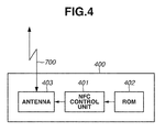
- Fig. 4 is a diagram illustrating an example of a hardware configuration of the NFC card 400.
- a ROM 402 stores user ID information held by the NFC card 400.
- the user ID information is stored in the ROM 402.
- a nonvolatile memory such as a flash ROM can be used.
- An NFC control unit 401 performs control to execute the NFC communication 700.
- An antenna 403 is an antenna for transmitting and receiving a radio wave to perform the NFC communication 700.
- Fig. 5 is a diagram illustrating an example of a user authentication screen 150 displayed on the operation unit 120 of the image forming apparatus 100.
- the user authentication screen illustrated in Fig. 5 is controlled by the CPU 101 based on a software program stored in the RAM 102 or the HDD 104. Screens described below are similarly controlled.
- the user authentication screen 150 is displayed on the operation unit 120 of the image forming apparatus 100.
- the NFC card 400 is brought into touch with the antenna 108 according to a message displayed on the operation unit 120.
- the image forming apparatus 100 performs user authentication based on user ID information received via the NFC communication 700.
- Fig. 6 is a diagram illustrating an example of a main menu screen 151 displayed on the operation unit 120 of the image forming apparatus 100.
- the screen is changed from a state of the user authentication screen 150 illustrated in Fig. 5 to the main menu screen 151.
- a title 152 of the menu screen is displayed as a main menu.
- a copy button 153 is selected when the user executes a copy function.
- a send button 154 is selected when the user executes a send function.
- a box button 155 is selected when the user executes a box function.
- a pairing button 156 is selected when the user executes a pairing function.
- the pairing function is for interconnecting the image forming apparatus 100 and the mobile terminal 300 via the LAN 600 and the wireless LAN communication 800.
- the pairing function By the pairing function, the IP address of the image forming apparatus 100 is transmitted to the mobile terminal 300 via the NFC communication 700, and then the mobile terminal 300 sets the received IP address as a transmission destination IP address of wireless LAN communication.
- the pairing function is not limited to this. Setting can be executed for interconnecting the image forming apparatus 100 and the mobile terminal 300 by using other wireless communication techniques such as Bluetooth (registered trademark).
- a "log out” button 157 is selected when the user logs out from the authentication state after ending the use of the image forming apparatus 100.
- the image forming apparatus 100 in the state of the main menu screen configuration is changed to the state of the user authentication screen configuration illustrated in Fig. 5 when the user selects the "log out” button 157.
- Fig. 7 is a diagram illustrating an example of a copy menu screen 160 displayed on the operation unit 120 of the image forming apparatus 100.
- a title 152 of the menu screen is displayed as copy.
- a copy magnification that is current copy function setting is equal (i.e., 100 %)
- a sheet size is A4, and the number of copies is 1.
- the user can change the copy magnification using magnification button 162 to one of predetermined magnifications of 25, 50, 100, 200, and 400 [%].
- a sheet selection button 163 is selected when the user changes a sheet size such as A4 or A3 set in a paper feed cassette deck of the image forming apparatus 100.
- a sorter button 164 is selected when the user changes an output form of a printed paper document. By using the sorter button 164, the user can change presence of sort processing or staple processing by page unit or group unit.
- a "two-sided” button 165 the user can instruct copying of one-side printed paper by two-sided printing, or copying of two-side printed paper by two-sided printing.
- a printing density adjustment bar 166 the user can change a density when copying.
- “other functions” button 167 the user can instruct a function of 2 in 1 printing for printing two pages in one page, bookbinding printing, copying with a different document size, single color printing, image quality adjustment, or area designated printing.
- the "log out” button 157 the image forming apparatus 100 in the state of the copy menu screen configuration is changed to the state of the user authentication screen configuration illustrated in Fig. 5 .
- Fig. 8 is a diagram illustrating an example of a send menu screen 170 displayed on the operation unit 120 of the image forming apparatus 100.
- the send menu screen 170 is used as a setting screen by the user for setting a send function of an address or the like.
- a title 152 of the menu screen is displayed as send.
- An "address book” button 171 is selected when the user designates, among addresses registered beforehand in the image forming apparatus 100, an address to which computerized document data is transmitted.
- a “new input” button 172 is selected when the user directly inputs the address to which the computerized document data is transmitted.
- a transmit to yourself button 173 is selected when the user transmits the computerized document data to himself.
- a color mode button 174 is used when the user sets a color mode for creating document data from paper document by using the image forming apparatus 100. The user can select, by using the color mode button 174, color setting or monochrome setting in addition to an automatic mode allowing the image forming apparatus 100 to make automatic determination.
- a resolution button 175 is for designating resolution when the user creates document data by using the image forming apparatus 100.
- a sheet size button 176 is used by the user for setting a sheet size of a paper document. The user can select, by using the sheet size button 176, A4 or A3 in addition to an automatic size mode allowing the image forming apparatus 100 to make automatic determination.
- a "two-sided document” button 177 the user can set whether the paper document is a one-sided document or a two-sided document.
- an “other functions” button 178 the user can instruct a function of image quality adjustment, density adjustment, or 2 in 1 layout.
- the image forming apparatus 100 in the state of the send menu screen configuration is changed to the state of the user authentication screen configuration illustrated in Fig. 5 .
- Fig. 9 is a diagram illustrating an example of a box menu screen 180 displayed on the operation unit 120 of the image forming apparatus 100.
- the box menu screen 180 is used as a screen by the user for using a box function.
- a title 152 of the menu screen is displayed as box.
- a "newly register” button 181 the user can register association of a box prepared beforehand with a name, an access right, or user ID information for an individual use.
- a "search” button 182 the user can perform searching based on a box name or a name of document data stored in the box.
- a box number 183 indicates a management number of a box prepared in the image forming apparatus 100, and, for example, 01, 02,..., are added in order from No. 00.
- a box name 184 indicates a box name registered by the user.
- a box use amount 185 indicates a capacity used by a box.
- a box number 00 button 186 indicates a name registered in the box number 00 and a box use amount. By selecting the button 186, the user can display a list of document data stored in the box number 00. Buttons from a box number 01 button 187 to a box number 05 button 191 are buttons having functions similar to that of the box number 00 button 186 corresponding to each box number. In the image forming apparatus 100, a collection of a certain number of buttons corresponding to the respective boxes is managed as a page.
- a box menu screen configuration illustrated in Fig. 9 the box numbers 00 to 05 are managed as one page.
- a page number 192 indicates a current number of pages displayed on the box menu screen 180 and a total number of pages.
- a first page of a total of ten pages is displayed.
- the user can display a previous page of the page displayed on the box menu screen configuration 180.
- the user can display a next page of the page displayed on the box menu screen configuration 180.
- the "log out" button 157 the image forming apparatus 100 in the state of the box menu screen configuration is changed to the state of the user authentication screen configuration illustrated in Fig. 5 .
- Fig. 10 is a diagram illustrating an example of a pairing menu screen 195 displayed on the operation unit 120 of the image forming apparatus 100.
- the screen is changed to a pairing menu screen 195.
- a title 152 of the menu screen is displayed as pairing.
- the user when pairing is performed between the image forming apparatus 100 and the mobile terminal 300, the user performs an operation according to a display on the pairing menu screen 195.
- the image forming apparatus 100 in the state of the pairing menu screen configuration is changed to the state of the user authentication screen configuration illustrated in Fig. 5 .
- Fig. 11 is a diagram illustrating an example of a local variable.
- the local variable illustrated in Fig. 11 is stored in a work area in the RAM 102, and accessed by the CPU 101 based on a software program stored in the RAM 102 or the HDD 104.
- a log-in flag 1001 is a flag for storing a current log-in state of the image forming apparatus 100.
- the CPU 101 stores "1" in the log-in flag 1001 in a state where the user has logged in, and "0" in the log-in flag 1001 in a state where the user has logged out.
- An address 1000 is an address of the log-in flag 1001 in the RAM 102, and an address value is 0xAAAA_B000.
- a screen ID variable 1003 is a variable for storing ID information of a screen configuration currently displayed on the operation unit 120 of the image forming apparatus 100.
- IDs are added to all the screen configurations.
- 0x0 is added to the ID of the user authentication screen configuration illustrated in Fig. 5 .
- 0x1 is added to the ID of the main menu screen configuration illustrated in Fig. 6 .
- 0x2 is added to the ID of the copy menu screen configuration illustrated in Fig. 7 .
- 0x3 is added to the ID of the send menu screen configuration illustrated in Fig. 8 .
- 0x4 is added to the ID of the box menu screen configuration illustrated in Fig. 9 .
- 0x5 is added to the ID of the pairing menu screen configuration illustrated in Fig. 10 .
- the CPU 101 stores 0x3 in the screen ID variable 1003 when a currently displayed screen configuration is the send menu screen configuration, and updates the screen ID variable 1003 each time the screen configuration is changed.
- the screen ID variable is an example of state information of an image processing apparatus.
- An address 1002 is an address of the screen ID variable 1003 in the RAM 102, and an address value is 0xAAAA_B004.
- the local variable is configured with 32 bits, which is in no way limitative.
- An address value allocated to the local variable, a flag value allocated to each state, and ID, which are optimal for the system, can be similarly set.
- Fig. 12 is a flowchart illustrating an example of information processing of the image forming apparatus 100 according to the first exemplary embodiment.
- the program stored in the ROM 103 is executed by the CPU 101.
- the CPU 101 executes processing based on the software program stored in the HDD 104 loaded in the RAM 102, and accordingly processing of the flowchart described below is realized. Processes of other flowcharts described below are similarly achieved.
- step S100 the CPU 101 initializes each module in the image forming apparatus 100. Specifically, the CPU 101 releases hardware resetting of each module to execute setting of various threshold values, securing of the local variable illustrated in Fig. 11 in the RAM 102, or initialization.
- step S101 the CPU 101 executes setting for the NFC control unit 107 to start the NFC communication 700.
- the CPU 101 in the setting for the NFC communication 700, the CPU 101 achieves the NFC communication 700 with the mobile terminal 300 by setting an NFC operation mode to P2P (peer-to-peer) and an initiator. Further, the CPU 101 achieves the NFC communication 700 with the NFC card 400 such as a Mifare (registered trademark) card or a FeliCa (registered trademark) card by setting the NFC operation mode to a reader/writer or the initiator. The CPU 101 achieves the NFC communication 700 with the mobile terminal 300 and the NFC card 400 by switching these two operation modes for each predetermined period of time.
- P2P peer-to-peer
- the CPU 101 achieves the NFC communication 700 with the NFC card 400 such as a Mifare (registered trademark) card or a FeliCa (registered trademark) card by setting the NFC operation mode to a reader/writer or the initiator.
- step S102 the CPU 101 clears a timer value for timeout detection.
- step S103 the CPU 101 starts counting of a timeout detection timer.
- timer processing is counting-up.
- the processing is not limited to the counting-up.
- the CPU 101 instructs the NFC control unit 107 to transmit data referred to as a polling request.
- the NFC control unit 107 transmits the polling request via the antenna 108.
- the NFC control unit 107 receives data so-called a response via the antenna 108.
- the NFC control unit 107 according to the first exemplary embodiment tries reception of user ID information from the NFC card 400 based on the protocol defined as the NFC communication 700.
- the CPU 101 can check a state of the NFC communication 700 from the NFC control unit 107.
- step S105 the CPU 101 compares the timer value with a preset threshold value.
- step S106 the CPU 101 determines that the image forming apparatus 100 has not been operated for a certain period of time, and prepares for turning OFF power to reduce power consumption of the image forming apparatus 100. Specifically, a part of the data stored in the RAM 102 is moved to the HDD 104 based in an instruction from the CPU 101.
- the CPU 101 instructs the power source control unit 125 to turn OFF power for the image forming apparatus 100.
- the power source control unit 125 turns OFF AC/DC conversion of the power source unit 126.
- step S104 the CPU 101 continues instructing the NFC control unit 107 to execute the NFC communication 700.
- step S108 the CPU 101 stops the timer counting processing to clear the timer value.
- step S109 the CPU 101 executes authentication processing based on an authentication database having the received user ID information stored in the image forming apparatus 100.
- the CPU 101 performs control to display the main menu screen configuration illustrated in Fig. 6 on the operation unit 120 when the user authentication processing normally ends.
- the CPU 101 stores "1" in the log-in flag 1001.
- step S110 the CPU 101 stores 0x1 indicating the ID of the main menu screen configuration in the screen ID variable.
- step S111 the CPU 101 starts timer counting.
- step S112 the CPU 101 detects a user's operation performed via the touch panel or the hardware key.
- step S113 the CPU 101 stops the timer counting processing to clear the timer value.
- step S114 the CPU 101 stores the ID of the screen configuration based on the user's operation in the screen ID variable.
- step S115 the CPU 101 executes a function of the image forming apparatus based on the user's operation.
- step S116 the CPU 101 instructs the NFC control unit 107 to execute the NFC communication 700.
- ID information of the mobile terminal 300 is acquired.
- the opposing device is the NFC card 400
- user ID information is acquired.
- the ID information of the mobile terminal 300 and the user ID information of the NFC card 400 are collectively referred to as NFC device ID information.
- step S112 the CPU 101 detects a user's operation performed via the touch panel or the hardware key again.
- step S117 the CPU 101 stops the timer counting processing to clear the timer value.
- step S118 the CPU 101 refers to the value stored in the screen ID variable to compare the ID with the ID of the send menu screen configuration.
- step S119 the CPU 101 adds the received NFC device ID information to a transmission destination address (destination) used in the send function.
- step S119 the CPU 101 of the image forming apparatus 101 adds, for example, a mail address corresponding to the user ID to the transmission destination address. Then, the image forming apparatus 100 executes the send function for an address registered in the transmission destination address.
- step S111 the CPU 101 starts timer counting.
- step S120 the CPU 101 compares the ID stored in the screen ID variable with the ID of the box menu screen configuration.
- step S121 the CPU 101 adds a box related to the received NFC device ID information to a storage destination box.
- the image forming apparatus 100 stores computerized document data in a box registered in the storage destination box. Then, in step S111, the CPU 101 starts timer counting.
- step S122 the CPU 101 compares the ID stored in the screen ID variable with the ID of the pairing menu screen configuration.
- step S123 the CPU 101 transmits an IP address set in the image forming apparatus 100 to the mobile terminal 300. Then, in step S111, the CPU 101 starts timer counting.
- step S124 the CPU 101 executes log-out processing. More specifically, the CPU 101 discards data about settings based on the user who is currently using the image forming apparatus 100, stores "0" in the log-in flag 1001, and then performs control to execute user authentication processing. Then, in step S109, the CPU 101 executes authentication processing based on the authentication database having the newly received NFC device ID information stored in the image forming apparatus 100.
- the NFC communication 700 is used in the processing of the flowchart of the image forming apparatus 100.
- a near field wireless communication means such as Radio Frequency IDentification (RFID) can be used. That is similar to the exemplary embodiments described below.
- RFID Radio Frequency IDentification
- the CPU 101 stores the state of the device (e.g., user interface (UI) menu screen configuration), and changes the handling of the received information according to the state of the device at the execution timing of the NFC communication.
- UI user interface
- An image forming apparatus 100 according to a second exemplary embodiment is different from the image forming apparatus 100 according to the first exemplary embodiment in processing when the NFC card 400 and the NFC communication 700 are executed.
- Fig. 13 is a flowchart illustrating an example of information processing of the image forming apparatus 100 according to the second exemplary embodiment. Descriptions of the information processing portions thereof similar to those of the image forming apparatus 100 according to the first exemplary embodiment illustrated in Fig. 12 (including steps S100 to S115 of Fig. 13A ) will be omitted.
- step S117 a CPU 101 stops timer counting processing to clear a timer value.
- step S118 the CPU 101 refers to a value stored in a screen ID variable to compare its ID with ID of a send menu screen configuration.
- step S118 When it is determined that the ID stored in the screen ID variable coincides with the ID of the send menu screen configuration (YES in step S118), the CPU 101 performs the following processing. Specifically, in step S150, the CPU 101 displays a menu for adding the received NFC device ID information to a transmission address used in a send function.
- steps S151 and S152 the CPU 101 detects a user's operation performed via a touch panel.
- step S150 the CPU 101 displays a menu for adding the NFC device ID information to the transmission address used in the send function.
- step S124 the CPU 101 executes log-out processing.
- step S119 the CPU 101 adds the received NFC device ID information to the transmission destination address used in the send function.
- step S120 the CPU 101 compares the ID stored in the screen ID variable with ID of a box menu screen configuration.
- the CPU 101 When it is determined that the ID stored in the screen ID variable coincides with the ID of the box menu screen configuration (YES in step S120), the CPU 101 performs the following processing. Specifically, in step S153, the CPU 101 displays a menu for adding a box related to the received NFC device ID information to a box storage destination box.
- the CPU 101 detects a user's operation performed via the touch panel.
- step S154 When it is determined that no user's operation performed via the touch panel has been detected (NO in step S154, and NO in step S155), the CPU 101 performs the following processing. Specifically, in step S153, the CPU 101 displays the menu for adding the box related to the received NFC device ID information to the box storage destination box.
- step S124 the CPU 101 executes log-out processing.
- step S121 the CPU 101 adds the box related to the received NFC device ID information to the storage destination box.
- the image forming apparatus 100 stores computerized document data in a box registered in the storage destination box.
- Fig. 14 is a diagram illustrating an example of a menu screen 1100 for adding the NFC device ID information displayed on an operation unit 120 of the image forming apparatus 100 according to the second exemplary embodiment to the transmission destination address used in the send function.
- a reception ID 1101 the NFC device ID information received via the NFC communication 700 is displayed.
- An "add to transmission destination address” button 1102 is for instructing addition of the received NFC device ID information as a transmission destination address used in the send function.
- a “log out” button 1103 is for instructing execution of log-out processing.
- Fig. 15 is a diagram illustrating an example of a menu screen 1110 for adding a box related to the NFC device ID information displayed on the operation unit 120 of the image forming apparatus 100 according to the second exemplary embodiment to a storage destination box.
- a reception ID 1111 the NFC device ID information received via the NFC communication 700 is displayed.
- a “log out” button 1113 is for instructing execution of log-out processing.
- the CPU 101 stores the state of the device (e.g., UI menu screen configuration), and displays the screen for changing handling of the received information according to the state of the device at the execution timing of the NFC communication to execute checking. Then, the CPU 101 changes the handling of the received information based on choice information selected by the user via the screen. As a result, an operation intuitive for the user can be achieved while checking.
- the state of the device e.g., UI menu screen configuration
- An image forming apparatus 100 according to a third exemplary embodiment is different from the image forming apparatuses 100 according to the first and second exemplary embodiments in processing when the NFC card 400 executes the NFC communication 700.
- Fig. 16 is a flowchart illustrating an example of information processing of the image forming apparatus 100 according to the third exemplary embodiment. Descriptions of information processing portions similar to those of the image forming apparatus 100 according to the first exemplary embodiment illustrated in Fig. 12 (including steps S100 to S119 on Fig. 16A ) will be omitted.
- step S117 a CPU 101 stops timer counting processing to clear a timer value.
- step S160 the CPU 101 displays a menu for selecting handling of the received NFC device ID information.
- the CPU 101 detects a user's operation performed via a touch panel.
- the CPU 101 When it is determined that no user's operation performed via the touch panel has been detected (NO in step S161, NO in step S162, and NO in step S163), the CPU 101 performs the following processing. Specifically, in a return to step S160, the CPU 101 displays the menu for selecting the handling of the received NFC device ID information.
- step S119 the CPU 101 adds the received NFC device ID information to the transmission destination address used in a send function.
- step S162 When the user selects addition of a storage destination box (YES in step S162) without selecting addition of the transmission destination address (NO in step S161), the CPU 101 performs the following processing.
- step S121 the CPU 101 adds a box related to the received NFC device ID information to a storage destination box.
- step S124 the CPU 101 executes log-out processing.
- Fig. 17 is a diagram illustrating an example of a menu screen 1120 for adding a transmission destination address or a storage destination box based on the NFC device ID information displayed on an operation unit 120 of the image forming apparatus 100 according to the third exemplary embodiment.
- a reception ID 1121 the NFC device ID information received via the NFC communication 700 is displayed.
- An "add to transmission destination address” button 1122 is for instructing addition of the received NFC device ID information as a transmission destination address used in the send function.
- An “add to storage destination box” button 1123 is for instructing addition of a box related to the received NFC device ID information as a storage destination box.
- a log out button 1124 is for instructing execution of log-out processing.
- the CPU 101 stores the state of the device (e.g., UI menu screen configuration), and changes handling of the received information according to the state of the device at the execution timing of the NFC communication.
- the state of the device e.g., UI menu screen configuration
- the CPU 101 displays the screen for changing the handling of the received information to perform checking under a predetermined condition. Then, the CPU 101 changes the handling of the received information based on choice information about a button or the like selected by the user via the screen.
- An image forming apparatus 100 according to a fourth exemplary embodiment is different from the image forming apparatuses 100 of the first to third exemplary embodiments in processing when the NFC card 400 executes the NFC communication 700.
- Fig. 18 is a flowchart illustrating an example of information processing of the image forming apparatus 100 according to the fourth exemplary embodiment. Descriptions of the information processing portions similar to those of the image forming apparatus 100 according to the first exemplary embodiment illustrated in Fig. 12 will be omitted.
- step S117 a CPU 101 stops timer counting processing to clear a timer value.
- step S170 the CPU 101 displays a menu for selecting handling of the received NFC device ID information.
- the CPU 101 detects a user's operation performed via a touch panel.
- the CPU 101 When it is determined that no user's operation performed via the touch panel has been detected (NO in step S171, NO in step S172, NO in step S173, and NO in step S174), the CPU 101 performs the following processing. Specifically, in a return to step S170, the CPU 101 displays the menu for selecting the handling of the received NFC device ID information.
- step S119 the CPU 101 adds the received NFC device ID information to a transmission destination address used in a send function.
- step S172 When the user selects addition of a storage destination box (YES in step S172) without selecting addition of the transmission destination address (NO in step S171), the CPU 101 performs the following processing. Specifically, in step S121, the CPU 101 adds a box related to the received NFC device ID information to a storage destination box.
- step S173 When the user selects execution of pairing (YES in step S173) without selecting addition of a transmission destination address (NO in step S171) and without selecting addition of a storage destination box (NO in step S172), the CPU 101 performs the following processing. Specifically, in step S123, the CPU 101 transmits an IP address set in the image forming apparatus 100 to a mobile terminal 300.
- step S174 When the user selects logging-out (YES in step S174) without selecting addition of the transmission destination address (NO in step S171), without selecting addition of the storage destination box (NO in step S172), and without selecting execution of pairing (NO in step S173), the CPU 101 performs the following processing. Specifically, in step S124, the CPU 101 executes log-out processing.
- Fig. 19 is a diagram illustrating an example of a menu screen 1130 for selecting addition of a transmission destination address or a storage destination box, or execution of pairing based on the NFC device ID information displayed on an operation unit 120 of the image forming apparatus 100 of the fourth exemplary embodiment.
- a reception ID 1131 the NFC device ID information received via the NFC communication 700 is displayed.
- An “add to storage destination box” button 1132 is for instructing addition of the received NFC device ID information as a transmission destination address used in the send function.
- An “add to storage destination box” button 1133 is for instructing addition of a box related to the received NFC device ID information as a storage destination box.
- a “execute pairing” button 1134 is for transmitting an IP address set in the image forming apparatus 100 to the mobile terminal 300.
- a log out button 1135 is for instructing execution of log-out processing.
- the CPU 101 changes handling of the received information based on choice information about a button or the like selected by the user via the screen.
- Embodiments of the present invention can also be realized by a computer of a system or apparatus that reads out and executes computer executable instructions recorded on a storage medium (e.g., non-transitory computer-readable storage medium) to perform the functions of one or more of the above-described embodiment(s) of the present invention, and by a method performed by the computer of the system or apparatus by, for example, reading out and executing the computer executable instructions from the storage medium to perform the functions of one or more of the above-described embodiment(s).
- the computer may comprise one or more of a central processing unit (CPU), micro processing unit (MPU), or other circuitry, and may include a network of separate computers or separate computer processors.
- the computer executable instructions may be provided to the computer, for example, from a network or the storage medium.
- the storage medium may include, for example, one or more of a hard disk, a random-access memory (RAM), a read only memory (ROM), a storage of distributed computing systems, an optical disk (such as a compact disc (CD), digital versatile disc (DVD), or Blu-ray Disc (BD)TM), a flash memory device, a memory card, and the like.
Abstract
Description
- The present invention relates to an information processing apparatus, a method for controlling the same, and a storage medium.
- Recently, a technique referred to as near field communication (NFC) that is one of near field wireless communication means has started to be mounted in a mobile terminal such as a smartphone or a tablet personal computer (PC). In specifications of the NFC, three functions are defined. The first is a reader/writer function that enables reading/writing of data from/into a NFC card or a NFC tag. The second is a peer-to-peer function that enables transmission/reception of various data via the NFC. The third is a card emulation function that enables execution of an operation similar to that of the NFC tag.
- In an image forming apparatus, an authentication function achieved thus far by using a radio frequency identification (RFID) tag to control permission/inhibition for a user can be replaced by the NFC. The NFC is usable in various devices. Accordingly, a wide variety of data including identification information, personal information such as a telephone number to device information such as an Internet Protocol (IP) address, is transmitted via the NFC. Even when the same information (e.g., ID information) is exchanged between NFC-mounted devices, the ID information may be used for the authentication function on a certain condition while the ID information may be used for registering user information on another condition. In the NFC, a communicable distance is about several centimeters (cm). Thus, data exchange can be performed between the two NFC-mounted devices by an intuitive operation referred to as touching for bringing the NFC-mounted devices into contact with each other. As a technique taking advantage of these features, Japanese Unexamined Patent Application Publication (Translation of PCT Application) No.
2009-531888 - However, according to the technique discussed in Japanese Unexamined Patent Application Publication (Translation of PCT Application) No.
2009-531888 - The present invention is directed to a technique capable of providing an intuitive operation of an information processing apparatus using a near field wireless communication to a user.
- According to a first aspect of the present invention, there is provided an information processing apparatus as specified in
claims 1 to 7. According to a second aspect of the present invention, there is provided a method for controlling an information processing apparatus as specified inclam 8. According to a third aspect of the present invention, there is provided a computer readable storage medium that stores a program for controlling the information processing apparatus as specified inclam 9. - Further features and aspects of the present invention will become apparent from the following detailed description of exemplary embodiments with reference to the attached drawings.
-
-
Fig. 1 is a diagram illustrating an example of a system configuration. -
Fig. 2 is a diagram illustrating an example of a hardware configuration of an image forming apparatus. -
Fig. 3 is a diagram illustrating an example of a hardware configuration of a mobile terminal. -
Fig. 4 is a diagram illustrating an example of a hardware configuration of an NFC card. -
Fig. 5 is a diagram illustrating an example of a user authentication screen displayed on an operation unit of the image forming apparatus. -
Fig. 6 is a diagram illustrating an example of a main menu screen displayed on the operation unit of the image forming apparatus. -
Fig. 7 is a diagram illustrating an example of a copy menu screen displayed on the operation unit of the image forming apparatus. -
Fig. 8 is a diagram illustrating an example of a send menu screen displayed on the operation unit of the image forming apparatus. -
Fig. 9 is a diagram illustrating an example of a box menu screen displayed on the operation unit of the image forming apparatus. -
Fig. 10 is a diagram illustrating an example of a pairing menu screen displayed on the operation unit of the image forming apparatus. -
Fig. 11 is a diagram illustrating an example of a local variable. -
Fig. 12 is a flowchart illustrating an example of information processing by an image forming apparatus according to a first exemplary embodiment. -
Fig. 13 (Fig. 13A + 13B) is a flowchart illustrating an example of information processing by an image forming apparatus according to a second exemplary embodiment. -
Fig. 14 is a diagram illustrating an example of a menu screen for adding NFC device ID information to a transmission destination address used in a send function. -
Fig. 15 is a diagram illustrating an example of a menu screen for adding a box related to the NFC device ID information to a storage destination box. -
Fig. 16 (16A + 16B) is a flowchart illustrating an example of information processing of an image forming apparatus according to a third exemplary embodiment. -
Fig. 17 is a diagram illustrating an example of a menu screen for adding a transmission destination address or a storage destination box based on NFC device ID information. -
Fig. 18 is a flowchart illustrating an example of information processing of an image forming apparatus according to a fourth exemplary embodiment. -
Fig. 19 is a diagram illustrating an example of a menu screen for selecting addition of a transmission destination address, a storage destination box, or execution of pairing based on NFC device ID information. - Various exemplary embodiments, features, and aspects of the invention will be described in detail below with reference to the drawings.
- Hereinafter, a first exemplary embodiment of the present invention will be described referring to the drawings.
-
Fig. 1 is a diagram illustrating an example of a system configuration. - The system includes an
image forming apparatus 100, a personal computer (PC) 200, amobile terminal 300, anNFC card 400, a wireless local area network (LAN)access point 500, and aLAN 600. - The
image forming apparatus 100 is an example of an information processing apparatus that has a copy function, a print function, a send function, and a box function. Specific processes of the respective functions are as described below. - The copy function is for copying a paper document.
- The print function is for printing a print job received via the
LAN 600. - The send function (transmission function) is for transmitting computerized document data to a designated address. The box function (file storage function) is for storing the computerized document data or computerized document data received via the
LAN 600. - The PC 200 can transmit a print job to the
image forming apparatus 100 based on document data via theLAN 600, and theimage forming apparatus 100 can refer to the computerized document data. - The
mobile terminal 300 is a portable information processing terminal that has anNFC communication 700 function and awireless LAN communication 800 function, which may correspond to a smartphone or a tablet PC. Themobile terminal 300 can communicate with theimage forming apparatus 100 via the NFCcommunication 700. Information transferred between themobile terminal 300 and theimage forming apparatus 100 may be, for example, an IP address or user ID information. Themobile terminal 300 can execute printing of image data by transmitting the image data in themobile terminal 300 to theimage forming apparatus 100 via thewireless LAN communication 800. Themobile terminal 300 can refer to the document data computerized by theimage forming apparatus 100 via thewireless LAN communication 800. - The
NFC card 400 is a card for transmitting the user ID information via the NFCcommunication 700. Theimage forming apparatus 100 receives the user ID information from theNFC card 400 via the NFCcommunication 700, and user authentication is performed based on an authentication database stored in theimage forming apparatus 100. Instead of an authentication database, a server for storing the user ID information may be separately prepared and theimage forming apparatus 100 may perform authentication processing in cooperation with the server via the LAN 600. - The wireless
LAN access point 500 has a function for enabling communication between themobile terminal 300 having a wireless LAN interface and a device connected to theLAN 600. - In a wireless communication interface according to the first exemplary embodiment, the system configuration using the
wireless LAN communication 800 is used. However, other wireless communication techniques such as Bluetooth (registered trademark) may be used. - The
LAN 600 is a network connection achieved by, for example, Ethernet (registered trademark). Theimage forming apparatus 100, thePC 200, and the wirelessLAN access point 500 are interconnected via theLAN 600. - The
mobile terminal 300 and theNFC card 400 are examples of recording media having wireless communication functions. Theimage forming apparatus 100 is an example of an image processing apparatus. -
Fig. 2 is a diagram illustrating an example of a hardware configuration of theimage forming apparatus 100. - A central processing unit (CPU) 101 controls the entire image forming apparatus.
- A random access memory (RAM) 102 is a memory for storing a program executed by the
CPU 101, which is also a work memory for temporarily storing data used for calculation by theCPU 101. A read-only memory (ROM) 103 stores a program used for starting theimage forming apparatus 100. - A hard disk drive (HDD) 104 stores a program or various settings for software concerning control of the
image forming apparatus 100 or document data to be stored. - An
operation unit 120, which allows a user to control theimage forming apparatus 100, inputs or outputs information between theimage forming apparatus 100 and the user. Theoperation unit 120 includes a liquid crystal display (LCD), a touch panel, and a hardware key. When the user selects a button displayed on the LCD, the user only needs to touch the displayed button. - The
operation unit 120 is an example of a display unit. - An operation interface (I/F) 105, which is an interface for the
operation unit 120, relays input or output data to theoperation unit 120. - The
CPU 101 controls theimage forming apparatus 100 based on key information received via the operation I/F 105 and selected by the user, and coordinate information on the touch panel. - A network I/
F 106 is an interface for exchanging data with an external device via theLAN 600. - A
NFC control unit 107 performs controls for exchanging data via theNFC 700. - An
antenna 108 is an antenna for transmitting and receiving a radio wave to performNFC communication 700. - A
flash ROM 127, which is connected to theNFC control unit 107, is used for temporarily storing data handled by theNFC control unit 107. Theimage forming apparatus 100 uses theflash ROM 127 for temporarily storing the data handled by theNFC control unit 107. However, it is not limited to this, and theimage forming apparatus 100 can use another nonvolatile memory or a combination of a static RAM (SRAM) with a battery. - A power
source control unit 125, which is a unit configured to control a power source of theimage forming apparatus 100, controls the power source according to an instruction from theCPU 101 or a user's operation of a power switch. - The
CPU 101 stops power supply to an unnecessary part via the powersource control unit 125 when it detects a state where no operation has been received from the user for a certain period of time or a state where no print job has been received via theLAN 600 for a certain period of time. The powersource control unit 125 can detect a power-OFF operation performed via the power switch, and it can notify theCPU 101 of a detected result as a power-OFF request. TheCPU 101 changes a state to a state where power for theimage forming apparatus 100 can be turned off by receiving the power-OFF request, and it instructs the powersource control unit 125 to stop the power supply. - A
power source unit 126, which is a power source for converting alternating-current (AC) power into direct-current (DC) power for theimage forming apparatus 100, turns ON or OFF a conversion operation according to an instruction from the powersource control unit 125. - The
CPU 101, theRAM 102, theROM 103, theHDD 104, the operation I/F 105, the network I/F 106, theNFC control unit 107, and the powersource control unit 125 are interconnected via asystem bus 114. - An image bus I/
F 109 is for relaying between thesystem bus 114 and animage bus 115 that connects units responsible for image processing, and converting a data structure. - A raster image processor (RIP) 110, a device I/
F 111, a printerimage processing unit 112, and a scannerimage processing unit 113 are connected to theimage bus 115. - The
RIP 110 converts a page description language (PDL) code or a display list into a bitmap image. - The device I/
F 111, which is an interface for connecting ascanner unit 130 and aprinter unit 140 to theimage bus 115, is connected to thescanner unit 130 via ascanner bus 116 and to theprinter unit 140 via ascanner bus 117. - The device I/
F 111 adjusts timing for transmitting image data received from thescanner unit 130 via thescanner bus 116 to theimage bus 115. Further, the device I/F 111 adjusts timing for transmitting the image data from theimage bus 115 to theprinter unit 140 via theprinter bus 117. - The
scanner unit 130 reads a document to generate image data. - The
printer unit 140 performs processing such as correction or resolution conversion for the image data to be printed and output, according to a print engine of theimage forming apparatus 100. -
Fig. 3 is a diagram illustrating an example of a hardware configuration of themobile terminal 300. - A
CPU 301 controls the entiremobile terminal 300. - A
RAM 302 is a memory for storing a program executed by theCPU 301, which is also a work memory for temporarily storing data to be used for calculation by theCPU 301. - A
flash ROM 303 stores the program or various data to be used by theCPU 301. - An
operation unit 304, which inputs or outputs information between the user and themobile terminal 300, includes an LCD and a touch panel. - A
camera 305 captures a still image or a moving image. - A wireless LAN I/
F 306 is an interface for exchanging data with an external device via thewireless LAN communication 800. - An
NFC control unit 307 performs control to execute theNFC communication 700. - An
antenna 308 is an antenna for transmitting and receiving a radio wave to perform theNFC communication 700. - The
CPU 301, theRAM 302, theflash ROM 303, theoperation unit 304, thecamera 305, the wireless LAN I/F 306, and theNFC control unit 307 are interconnected via asystem bus 309 to exchange data with one another. -
Fig. 4 is a diagram illustrating an example of a hardware configuration of theNFC card 400. - A
ROM 402 stores user ID information held by theNFC card 400. In theNFC card 400, the user ID information is stored in theROM 402. However, it is not limited to this, and a nonvolatile memory such as a flash ROM can be used. AnNFC control unit 401 performs control to execute theNFC communication 700. Anantenna 403 is an antenna for transmitting and receiving a radio wave to perform theNFC communication 700. -
Fig. 5 is a diagram illustrating an example of auser authentication screen 150 displayed on theoperation unit 120 of theimage forming apparatus 100. - The user authentication screen illustrated in
Fig. 5 is controlled by theCPU 101 based on a software program stored in theRAM 102 or theHDD 104. Screens described below are similarly controlled. - The
user authentication screen 150 is displayed on theoperation unit 120 of theimage forming apparatus 100. TheNFC card 400 is brought into touch with theantenna 108 according to a message displayed on theoperation unit 120. Theimage forming apparatus 100 performs user authentication based on user ID information received via theNFC communication 700. -
Fig. 6 is a diagram illustrating an example of amain menu screen 151 displayed on theoperation unit 120 of theimage forming apparatus 100. - When the user ID authentication processing normally ends, the screen is changed from a state of the
user authentication screen 150 illustrated inFig. 5 to themain menu screen 151. - A
title 152 of the menu screen is displayed as a main menu. - A
copy button 153 is selected when the user executes a copy function. Asend button 154 is selected when the user executes a send function. Abox button 155 is selected when the user executes a box function. Apairing button 156 is selected when the user executes a pairing function. - The pairing function is for interconnecting the
image forming apparatus 100 and themobile terminal 300 via theLAN 600 and thewireless LAN communication 800. - By the pairing function, the IP address of the
image forming apparatus 100 is transmitted to themobile terminal 300 via theNFC communication 700, and then themobile terminal 300 sets the received IP address as a transmission destination IP address of wireless LAN communication. However, the pairing function is not limited to this. Setting can be executed for interconnecting theimage forming apparatus 100 and themobile terminal 300 by using other wireless communication techniques such as Bluetooth (registered trademark). - A "log out"
button 157 is selected when the user logs out from the authentication state after ending the use of theimage forming apparatus 100. Theimage forming apparatus 100 in the state of the main menu screen configuration is changed to the state of the user authentication screen configuration illustrated inFig. 5 when the user selects the "log out"button 157. -
Fig. 7 is a diagram illustrating an example of acopy menu screen 160 displayed on theoperation unit 120 of theimage forming apparatus 100. - When the user selects the
copy button 153 from the state of themain menu screen 151 illustrated inFig. 6 , the screen is changed to acopy menu screen 160. - A
title 152 of the menu screen is displayed as copy. In a copystate display window 161, a copy magnification that is current copy function setting is equal (i.e., 100 %), a sheet size is A4, and the number of copies is 1. The user can change the copy magnification usingmagnification button 162 to one of predetermined magnifications of 25, 50, 100, 200, and 400 [%]. Asheet selection button 163 is selected when the user changes a sheet size such as A4 or A3 set in a paper feed cassette deck of theimage forming apparatus 100. Asorter button 164 is selected when the user changes an output form of a printed paper document. By using thesorter button 164, the user can change presence of sort processing or staple processing by page unit or group unit. By selecting a "two-sided"button 165, the user can instruct copying of one-side printed paper by two-sided printing, or copying of two-side printed paper by two-sided printing. By selecting a printingdensity adjustment bar 166, the user can change a density when copying. By selecting "other functions"button 167, the user can instruct a function of 2 in 1 printing for printing two pages in one page, bookbinding printing, copying with a different document size, single color printing, image quality adjustment, or area designated printing. When the user selects the "log out"button 157, theimage forming apparatus 100 in the state of the copy menu screen configuration is changed to the state of the user authentication screen configuration illustrated inFig. 5 . -
Fig. 8 is a diagram illustrating an example of asend menu screen 170 displayed on theoperation unit 120 of theimage forming apparatus 100. - When the user selects a
send button 154 from the state of themain menu screen 151 illustrated inFig. 6 , the screen is changed to asend menu screen 170. Thesend menu screen 170 is used as a setting screen by the user for setting a send function of an address or the like. - A
title 152 of the menu screen is displayed as send. An "address book"button 171 is selected when the user designates, among addresses registered beforehand in theimage forming apparatus 100, an address to which computerized document data is transmitted. A "new input"button 172 is selected when the user directly inputs the address to which the computerized document data is transmitted. A transmit to yourselfbutton 173 is selected when the user transmits the computerized document data to himself. Acolor mode button 174 is used when the user sets a color mode for creating document data from paper document by using theimage forming apparatus 100. The user can select, by using thecolor mode button 174, color setting or monochrome setting in addition to an automatic mode allowing theimage forming apparatus 100 to make automatic determination. Aresolution button 175 is for designating resolution when the user creates document data by using theimage forming apparatus 100. Asheet size button 176 is used by the user for setting a sheet size of a paper document. The user can select, by using thesheet size button 176, A4 or A3 in addition to an automatic size mode allowing theimage forming apparatus 100 to make automatic determination. By selecting a "two-sided document"button 177, the user can set whether the paper document is a one-sided document or a two-sided document. By selecting an "other functions"button 178, the user can instruct a function of image quality adjustment, density adjustment, or 2 in 1 layout. When the user selects the "log out"button 157, theimage forming apparatus 100 in the state of the send menu screen configuration is changed to the state of the user authentication screen configuration illustrated inFig. 5 . -
Fig. 9 is a diagram illustrating an example of abox menu screen 180 displayed on theoperation unit 120 of theimage forming apparatus 100. - When the user selects a
box button 155 from the state of themain menu screen 151 illustrated inFig. 6 , the screen is changed to abox menu screen 180. Thebox menu screen 180 is used as a screen by the user for using a box function. - A
title 152 of the menu screen is displayed as box. By selecting a "newly register"button 181, the user can register association of a box prepared beforehand with a name, an access right, or user ID information for an individual use. By selecting a "search"button 182, the user can perform searching based on a box name or a name of document data stored in the box. Abox number 183 indicates a management number of a box prepared in theimage forming apparatus 100, and, for example, 01, 02,..., are added in order from No. 00. Abox name 184 indicates a box name registered by the user. - A
box use amount 185 indicates a capacity used by a box. Abox number 00button 186 indicates a name registered in thebox number 00 and a box use amount. By selecting thebutton 186, the user can display a list of document data stored in thebox number 00. Buttons from a box number 01button 187 to a box number 05button 191 are buttons having functions similar to that of thebox number 00button 186 corresponding to each box number. In theimage forming apparatus 100, a collection of a certain number of buttons corresponding to the respective boxes is managed as a page. - In a box menu screen configuration illustrated in
Fig. 9 , thebox numbers 00 to 05 are managed as one page. Apage number 192 indicates a current number of pages displayed on thebox menu screen 180 and a total number of pages. In the box menu screen configuration illustrated inFig. 9 , a first page of a total of ten pages is displayed. By selecting a previouspage selection button 193, the user can display a previous page of the page displayed on the boxmenu screen configuration 180. By selecting a nextpage selection button 194, the user can display a next page of the page displayed on the boxmenu screen configuration 180. When the user selects the "log out"button 157, theimage forming apparatus 100 in the state of the box menu screen configuration is changed to the state of the user authentication screen configuration illustrated inFig. 5 . -
Fig. 10 is a diagram illustrating an example of apairing menu screen 195 displayed on theoperation unit 120 of theimage forming apparatus 100. - When the user selects the
pairing button 156 from the state of themain menu screen 151 illustrated inFig. 6 , the screen is changed to apairing menu screen 195. - A
title 152 of the menu screen is displayed as pairing. In the first exemplary embodiment, when pairing is performed between theimage forming apparatus 100 and themobile terminal 300, the user performs an operation according to a display on thepairing menu screen 195. When the user selects the "log out"button 157, theimage forming apparatus 100 in the state of the pairing menu screen configuration is changed to the state of the user authentication screen configuration illustrated inFig. 5 . -
Fig. 11 is a diagram illustrating an example of a local variable. - The local variable illustrated in
Fig. 11 is stored in a work area in theRAM 102, and accessed by theCPU 101 based on a software program stored in theRAM 102 or theHDD 104. - A log-in
flag 1001 is a flag for storing a current log-in state of theimage forming apparatus 100. TheCPU 101 stores "1" in the log-inflag 1001 in a state where the user has logged in, and "0" in the log-inflag 1001 in a state where the user has logged out. - An
address 1000 is an address of the log-inflag 1001 in theRAM 102, and an address value is 0xAAAA_B000. - A
screen ID variable 1003 is a variable for storing ID information of a screen configuration currently displayed on theoperation unit 120 of theimage forming apparatus 100. In the first exemplary embodiment, IDs are added to all the screen configurations. 0x0 is added to the ID of the user authentication screen configuration illustrated inFig. 5 . 0x1 is added to the ID of the main menu screen configuration illustrated inFig. 6 . 0x2 is added to the ID of the copy menu screen configuration illustrated inFig. 7 . 0x3 is added to the ID of the send menu screen configuration illustrated inFig. 8 . 0x4 is added to the ID of the box menu screen configuration illustrated inFig. 9 . 0x5 is added to the ID of the pairing menu screen configuration illustrated inFig. 10 . TheCPU 101 stores 0x3 in thescreen ID variable 1003 when a currently displayed screen configuration is the send menu screen configuration, and updates thescreen ID variable 1003 each time the screen configuration is changed. - The screen ID variable is an example of state information of an image processing apparatus.
- An
address 1002 is an address of thescreen ID variable 1003 in theRAM 102, and an address value is 0xAAAA_B004. In the first exemplary embodiment, the local variable is configured with 32 bits, which is in no way limitative. An address value allocated to the local variable, a flag value allocated to each state, and ID, which are optimal for the system, can be similarly set. -
Fig. 12 is a flowchart illustrating an example of information processing of theimage forming apparatus 100 according to the first exemplary embodiment. - After power-ON of the
image forming apparatus 100, the program stored in theROM 103 is executed by theCPU 101. TheCPU 101 executes processing based on the software program stored in theHDD 104 loaded in theRAM 102, and accordingly processing of the flowchart described below is realized. Processes of other flowcharts described below are similarly achieved. - In step S100, the
CPU 101 initializes each module in theimage forming apparatus 100. Specifically, theCPU 101 releases hardware resetting of each module to execute setting of various threshold values, securing of the local variable illustrated inFig. 11 in theRAM 102, or initialization. - In step S101, the
CPU 101 executes setting for theNFC control unit 107 to start theNFC communication 700. In the first exemplary embodiment, in the setting for theNFC communication 700, theCPU 101 achieves theNFC communication 700 with themobile terminal 300 by setting an NFC operation mode to P2P (peer-to-peer) and an initiator. Further, theCPU 101 achieves theNFC communication 700 with theNFC card 400 such as a Mifare (registered trademark) card or a FeliCa (registered trademark) card by setting the NFC operation mode to a reader/writer or the initiator. TheCPU 101 achieves theNFC communication 700 with themobile terminal 300 and theNFC card 400 by switching these two operation modes for each predetermined period of time. - In step S102, the
CPU 101 clears a timer value for timeout detection. - In step S103, the
CPU 101 starts counting of a timeout detection timer. In the first exemplary embodiment, timer processing is counting-up. However, the processing is not limited to the counting-up. - The
CPU 101 instructs theNFC control unit 107 to transmit data referred to as a polling request. TheNFC control unit 107 transmits the polling request via theantenna 108. When themobile terminal 300 or theNFC card 400 is present in a space within a radio wave accessible range via theNFC communication 700, theNFC control unit 107 receives data so-called a response via theantenna 108. In step S104, theNFC control unit 107 according to the first exemplary embodiment tries reception of user ID information from theNFC card 400 based on the protocol defined as theNFC communication 700. TheCPU 101 can check a state of theNFC communication 700 from theNFC control unit 107. - When reception of the user ID information from the
NFC card 400 fails (NO in step S104), in step S105, theCPU 101 compares the timer value with a preset threshold value. - When the timer value exceeds the threshold value (YES in step S105), in step S106, the
CPU 101 determines that theimage forming apparatus 100 has not been operated for a certain period of time, and prepares for turning OFF power to reduce power consumption of theimage forming apparatus 100. Specifically, a part of the data stored in theRAM 102 is moved to theHDD 104 based in an instruction from theCPU 101. - The
CPU 101 instructs the powersource control unit 125 to turn OFF power for theimage forming apparatus 100. In step S107, the powersource control unit 125 turns OFF AC/DC conversion of thepower source unit 126. - On the other hand, when the timer value does not exceed the threshold value (NO in step S105), in step S104, the
CPU 101 continues instructing theNFC control unit 107 to execute theNFC communication 700. - When it is determined that the
NFC control unit 107 has received the user ID information (YES in step S104), in step S108, theCPU 101 stops the timer counting processing to clear the timer value. - In step S109, the
CPU 101 executes authentication processing based on an authentication database having the received user ID information stored in theimage forming apparatus 100. TheCPU 101 performs control to display the main menu screen configuration illustrated inFig. 6 on theoperation unit 120 when the user authentication processing normally ends. - The
CPU 101 stores "1" in the log-inflag 1001. In step S110, theCPU 101 stores 0x1 indicating the ID of the main menu screen configuration in the screen ID variable. - In step S111, the
CPU 101 starts timer counting. - In step S112, the
CPU 101 detects a user's operation performed via the touch panel or the hardware key. - When a user's operation has been detected (YES in step S112), in step S113, the
CPU 101 stops the timer counting processing to clear the timer value. - In step S114, the
CPU 101 stores the ID of the screen configuration based on the user's operation in the screen ID variable. - In step S115, the
CPU 101 executes a function of the image forming apparatus based on the user's operation. - On the other hand, when no user's operation has been detected (NO in step S112), in step S116, the
CPU 101 instructs theNFC control unit 107 to execute theNFC communication 700. When an opposing device is themobile terminal 300, ID information of themobile terminal 300 is acquired. When the opposing device is theNFC card 400, user ID information is acquired. In the processing of theimage forming apparatus 100, the ID information of themobile terminal 300 and the user ID information of theNFC card 400 are collectively referred to as NFC device ID information. - When it is determined that no NFC device ID information has been received (NO in step S116), in step S112, the
CPU 101 detects a user's operation performed via the touch panel or the hardware key again. - On the other hand, when it is determined that NFC device ID information has been received (YES in step S116), in step S117, the
CPU 101 stops the timer counting processing to clear the timer value. - In step S118, the
CPU 101 refers to the value stored in the screen ID variable to compare the ID with the ID of the send menu screen configuration. - When it is determined that the ID stored in the screen ID variable coincides with the ID of the send menu screen configuration (YES in step S118), in step S119, the
CPU 101 adds the received NFC device ID information to a transmission destination address (destination) used in the send function. In step S119, theCPU 101 of theimage forming apparatus 101 adds, for example, a mail address corresponding to the user ID to the transmission destination address. Then, theimage forming apparatus 100 executes the send function for an address registered in the transmission destination address. In step S111, theCPU 101 starts timer counting. - On the other hand, when it is determined that the ID stored in the screen ID variable does not coincide with the ID of the send menu screen configuration (NO in step S118), in step S120, the
CPU 101 compares the ID stored in the screen ID variable with the ID of the box menu screen configuration. - When it is determined that the ID stored in the screen ID variable coincides with the ID of the box menu screen configuration (YES in step S120), in step S121, the
CPU 101 adds a box related to the received NFC device ID information to a storage destination box. In the first exemplary embodiment, theimage forming apparatus 100 stores computerized document data in a box registered in the storage destination box. Then, in step S111, theCPU 101 starts timer counting. - On the other hand, when it is determined that the ID stored in the screen ID variable does not coincide with the ID of the box menu screen configuration (NO in step S120), in step S122, the
CPU 101 compares the ID stored in the screen ID variable with the ID of the pairing menu screen configuration. - When it is determined that the ID stored in the screen ID variable coincides with the ID of the pairing menu screen configuration (YES in step S122), in step S123, the
CPU 101 transmits an IP address set in theimage forming apparatus 100 to themobile terminal 300. Then, in step S111, theCPU 101 starts timer counting. - On the other hand, when it is determined that the ID stored in the screen ID variable does not coincide with the ID of the pairing menu screen configuration (NO in step S122), in step S124, the
CPU 101 executes log-out processing. More specifically, theCPU 101 discards data about settings based on the user who is currently using theimage forming apparatus 100, stores "0" in the log-inflag 1001, and then performs control to execute user authentication processing. Then, in step S109, theCPU 101 executes authentication processing based on the authentication database having the newly received NFC device ID information stored in theimage forming apparatus 100. - In the first exemplary embodiment, in the processing of the flowchart of the
image forming apparatus 100, theNFC communication 700 is used. However, it is not limited to this, and a near field wireless communication means such as Radio Frequency IDentification (RFID) can be used. That is similar to the exemplary embodiments described below. - Thus, according to the present exemplary embodiment, the
CPU 101 stores the state of the device (e.g., user interface (UI) menu screen configuration), and changes the handling of the received information according to the state of the device at the execution timing of the NFC communication. As a result, an intuitive operation can be achieved. - An
image forming apparatus 100 according to a second exemplary embodiment is different from theimage forming apparatus 100 according to the first exemplary embodiment in processing when theNFC card 400 and theNFC communication 700 are executed. -
Fig. 13 is a flowchart illustrating an example of information processing of theimage forming apparatus 100 according to the second exemplary embodiment. Descriptions of the information processing portions thereof similar to those of theimage forming apparatus 100 according to the first exemplary embodiment illustrated inFig. 12 (including steps S100 to S115 ofFig. 13A ) will be omitted. - When it is determined that NFC device ID information has been received (YES in step S116), in step S117, a
CPU 101 stops timer counting processing to clear a timer value. - In step S118, the
CPU 101 refers to a value stored in a screen ID variable to compare its ID with ID of a send menu screen configuration. - When it is determined that the ID stored in the screen ID variable coincides with the ID of the send menu screen configuration (YES in step S118), the
CPU 101 performs the following processing. Specifically, in step S150, theCPU 101 displays a menu for adding the received NFC device ID information to a transmission address used in a send function. - In steps S151 and S152, the
CPU 101 detects a user's operation performed via a touch panel. - When it is determined that no user's operation performed via the touch panel has been detected (NO in step S151, and NO in step S152), the
CPU 101 performs the following processing. Specifically, in step S150, theCPU 101 displays a menu for adding the NFC device ID information to the transmission address used in the send function. - When a user selects logging-out (YES in step S152), in step S124, the
CPU 101 executes log-out processing. - On the other hand, when the user selects addition of the transmission destination address (YES in step S151), in step S119, the
CPU 101 adds the received NFC device ID information to the transmission destination address used in the send function. - On the other hand, when it is determined that the ID stored in the screen ID variable does not coincide with the ID of the send menu screen configuration (NO in step S118), in step S120, the
CPU 101 compares the ID stored in the screen ID variable with ID of a box menu screen configuration. - When it is determined that the ID stored in the screen ID variable coincides with the ID of the box menu screen configuration (YES in step S120), the
CPU 101 performs the following processing. Specifically, in step S153, theCPU 101 displays a menu for adding a box related to the received NFC device ID information to a box storage destination box. - In steps S154 and S155, the
CPU 101 detects a user's operation performed via the touch panel. - When it is determined that no user's operation performed via the touch panel has been detected (NO in step S154, and NO in step S155), the
CPU 101 performs the following processing. Specifically, in step S153, theCPU 101 displays the menu for adding the box related to the received NFC device ID information to the box storage destination box. - When the user selects logging-out (YES in step S155), in step S124, the
CPU 101 executes log-out processing. - On the other hand, when the user selects addition of the storage destination box (YES in step S154), in step S121, the
CPU 101 adds the box related to the received NFC device ID information to the storage destination box. In the second exemplary embodiment, theimage forming apparatus 100 stores computerized document data in a box registered in the storage destination box. -
Fig. 14 is a diagram illustrating an example of amenu screen 1100 for adding the NFC device ID information displayed on anoperation unit 120 of theimage forming apparatus 100 according to the second exemplary embodiment to the transmission destination address used in the send function. - In a reception ID 1101, the NFC device ID information received via the
NFC communication 700 is displayed. An "add to transmission destination address"button 1102 is for instructing addition of the received NFC device ID information as a transmission destination address used in the send function. A "log out"button 1103 is for instructing execution of log-out processing. -
Fig. 15 is a diagram illustrating an example of amenu screen 1110 for adding a box related to the NFC device ID information displayed on theoperation unit 120 of theimage forming apparatus 100 according to the second exemplary embodiment to a storage destination box. - In a
reception ID 1111, the NFC device ID information received via theNFC communication 700 is displayed. An "add to storage destination box"button 1112 for instructing addition of the received NFC device ID information as a storage destination box. A "log out"button 1113 is for instructing execution of log-out processing. - Thus, according to the present exemplary embodiment, the
CPU 101 stores the state of the device (e.g., UI menu screen configuration), and displays the screen for changing handling of the received information according to the state of the device at the execution timing of the NFC communication to execute checking. Then, theCPU 101 changes the handling of the received information based on choice information selected by the user via the screen. As a result, an operation intuitive for the user can be achieved while checking. - An
image forming apparatus 100 according to a third exemplary embodiment is different from theimage forming apparatuses 100 according to the first and second exemplary embodiments in processing when theNFC card 400 executes theNFC communication 700. -
Fig. 16 is a flowchart illustrating an example of information processing of theimage forming apparatus 100 according to the third exemplary embodiment. Descriptions of information processing portions similar to those of theimage forming apparatus 100 according to the first exemplary embodiment illustrated inFig. 12 (including steps S100 to S119 onFig. 16A ) will be omitted. - When it is determined that NFC device ID information has been received (YES in step S116), in step S117, a
CPU 101 stops timer counting processing to clear a timer value. - When it is determined that ID stored in a screen ID variable does not coincide with ID of any of a send menu screen configuration, a box menu screen configuration, and a pairing menu screen configuration (NO in step S118, NO in step S120, and NO in step S122), the
CPU 101 performs the following processing. In step S160, theCPU 101 displays a menu for selecting handling of the received NFC device ID information. - In steps S161, S162, and S163, the
CPU 101 detects a user's operation performed via a touch panel. - When it is determined that no user's operation performed via the touch panel has been detected (NO in step S161, NO in step S162, and NO in step S163), the
CPU 101 performs the following processing. Specifically, in a return to step S160, theCPU 101 displays the menu for selecting the handling of the received NFC device ID information. - When the user selects addition of a transmission destination address (YES in step S161), in step S119, the
CPU 101 adds the received NFC device ID information to the transmission destination address used in a send function. - When the user selects addition of a storage destination box (YES in step S162) without selecting addition of the transmission destination address (NO in step S161), the
CPU 101 performs the following processing. In step S121, theCPU 101 adds a box related to the received NFC device ID information to a storage destination box. When the user selects logging-out (YES in step S163) without selecting addition of the transmission destination address (NO in step S161) and without selecting addition of the storage destination box (NO in step S162), theCPU 101 performs the following processing. In step S124, theCPU 101 executes log-out processing. -
Fig. 17 is a diagram illustrating an example of amenu screen 1120 for adding a transmission destination address or a storage destination box based on the NFC device ID information displayed on anoperation unit 120 of theimage forming apparatus 100 according to the third exemplary embodiment. - In a
reception ID 1121, the NFC device ID information received via theNFC communication 700 is displayed. An "add to transmission destination address"button 1122 is for instructing addition of the received NFC device ID information as a transmission destination address used in the send function. An "add to storage destination box"button 1123 is for instructing addition of a box related to the received NFC device ID information as a storage destination box. A log outbutton 1124 is for instructing execution of log-out processing. - Thus, according to the present exemplary embodiment, the
CPU 101 stores the state of the device (e.g., UI menu screen configuration), and changes handling of the received information according to the state of the device at the execution timing of the NFC communication. As a result, an intuitive operation can be achieved. - Even in a state where the state of the device at the execution timing of the NFC communication is not set beforehand, the
CPU 101 displays the screen for changing the handling of the received information to perform checking under a predetermined condition. Then, theCPU 101 changes the handling of the received information based on choice information about a button or the like selected by the user via the screen. - As a result, an operation intuitive for the user can be achieved.
- An
image forming apparatus 100 according to a fourth exemplary embodiment is different from theimage forming apparatuses 100 of the first to third exemplary embodiments in processing when theNFC card 400 executes theNFC communication 700. -
Fig. 18 is a flowchart illustrating an example of information processing of theimage forming apparatus 100 according to the fourth exemplary embodiment. Descriptions of the information processing portions similar to those of theimage forming apparatus 100 according to the first exemplary embodiment illustrated inFig. 12 will be omitted. - When it is determined that NFC device ID information has been received (YES in step S116), in step S117, a
CPU 101 stops timer counting processing to clear a timer value. - Then, in step S170, the
CPU 101 displays a menu for selecting handling of the received NFC device ID information. - In steps S171, S172, S173, and S174, the
CPU 101 detects a user's operation performed via a touch panel. - When it is determined that no user's operation performed via the touch panel has been detected (NO in step S171, NO in step S172, NO in step S173, and NO in step S174), the
CPU 101 performs the following processing. Specifically, in a return to step S170, theCPU 101 displays the menu for selecting the handling of the received NFC device ID information. - When the user selects addition of a transmission destination address (YES in step S171), in step S119, the
CPU 101 adds the received NFC device ID information to a transmission destination address used in a send function. - When the user selects addition of a storage destination box (YES in step S172) without selecting addition of the transmission destination address (NO in step S171), the
CPU 101 performs the following processing. Specifically, in step S121, theCPU 101 adds a box related to the received NFC device ID information to a storage destination box. - When the user selects execution of pairing (YES in step S173) without selecting addition of a transmission destination address (NO in step S171) and without selecting addition of a storage destination box (NO in step S172), the
CPU 101 performs the following processing. Specifically, in step S123, theCPU 101 transmits an IP address set in theimage forming apparatus 100 to amobile terminal 300. - When the user selects logging-out (YES in step S174) without selecting addition of the transmission destination address (NO in step S171), without selecting addition of the storage destination box (NO in step S172), and without selecting execution of pairing (NO in step S173), the
CPU 101 performs the following processing. Specifically, in step S124, theCPU 101 executes log-out processing. -
Fig. 19 is a diagram illustrating an example of amenu screen 1130 for selecting addition of a transmission destination address or a storage destination box, or execution of pairing based on the NFC device ID information displayed on anoperation unit 120 of theimage forming apparatus 100 of the fourth exemplary embodiment. - In a
reception ID 1131, the NFC device ID information received via theNFC communication 700 is displayed. An "add to storage destination box"button 1132 is for instructing addition of the received NFC device ID information as a transmission destination address used in the send function. An "add to storage destination box"button 1133 is for instructing addition of a box related to the received NFC device ID information as a storage destination box. A "execute pairing"button 1134 is for transmitting an IP address set in theimage forming apparatus 100 to themobile terminal 300. A log outbutton 1135 is for instructing execution of log-out processing. - Thus, according to the present exemplary embodiment, the
CPU 101 changes handling of the received information based on choice information about a button or the like selected by the user via the screen. - As a result, an operation intuitive for the user can be achieved.
- Embodiments of the present invention can also be realized by a computer of a system or apparatus that reads out and executes computer executable instructions recorded on a storage medium (e.g., non-transitory computer-readable storage medium) to perform the functions of one or more of the above-described embodiment(s) of the present invention, and by a method performed by the computer of the system or apparatus by, for example, reading out and executing the computer executable instructions from the storage medium to perform the functions of one or more of the above-described embodiment(s). The computer may comprise one or more of a central processing unit (CPU), micro processing unit (MPU), or other circuitry, and may include a network of separate computers or separate computer processors. The computer executable instructions may be provided to the computer, for example, from a network or the storage medium. The storage medium may include, for example, one or more of a hard disk, a random-access memory (RAM), a read only memory (ROM), a storage of distributed computing systems, an optical disk (such as a compact disc (CD), digital versatile disc (DVD), or Blu-ray Disc (BD)™), a flash memory device, a memory card, and the like.
- While the present invention has been described with reference to exemplary embodiments, it is to be understood that the invention is not limited to the disclosed exemplary embodiments. The scope of the following claims is to be accorded the broadest interpretation so as to encompass all such modifications and equivalent structures and functions.
Claims (9)
- An information processing apparatus (100, 200) capable of performing near field wireless communication (700), comprising:a display means (120) configured to display a screen;an acquisition means (300; 400) configured to acquire user information from an external apparatus by using the near field wireless communication (700); anda processing means (101) configured to determine how to handle the user information acquired by the acquisition means according to a type of the screen displayed by the display means.
- The information processing apparatus (100, 200) according to claim 1, further comprising a specification means configured to specify the type of the screen to be displayed by the display means (120) when the acquisition means has acquired the user information,
wherein the processing means (101) is configured to determine how to handle the user information acquired by the acquisition means according to the type of the screen specified by the specification means. - The information processing apparatus (100, 200) according to claim 1 or 2,
wherein, when the screen displayed by the display means is a screen concerning authentication, the processing means is configured to execute authentication processing by using the user information. - The information processing apparatus (100, 200) according to any one of claims 1 to 3,
wherein, when the screen displayed by the display means is a screen concerning a transmission function, the processing means is configured to set a transmission destination of data by using the user information. - The information processing apparatus (100, 200) according to claim 4,
wherein the processing means is configured to set an address corresponding to the user information as the transmission destination of the data. - The information processing apparatus (100, 200) according to any one of claims 4 or 5, further comprising a reading means (130) configured to read a document to generate image data,
wherein the processing means is configured to set a transmission destination of the image data by using the user information. - The information processing apparatus according to any one of claims 1 to 6,
wherein, when the display means displays a screen concerning a box function, the processing means sets a box corresponding to the user information as a storage destination of data. - A method for controlling an information processing apparatus capable of performing near field wireless communication, comprising:displaying a screen;acquiring user information from an external apparatus by using the near field wireless communication; anddetermining how to handle the acquired user information according to a type of the displayed screen.
- A non-transitory computer-readable storage medium storing a program for causing a computer to execute the method for controlling the image forming apparatus according to claim 8.
Applications Claiming Priority (1)
| Application Number | Priority Date | Filing Date | Title |
|---|---|---|---|
| JP2013170496A JP6300467B2 (en) | 2013-08-20 | 2013-08-20 | Image processing apparatus, information processing method, and program |
Publications (2)
| Publication Number | Publication Date |
|---|---|
| EP2840529A1 true EP2840529A1 (en) | 2015-02-25 |
| EP2840529B1 EP2840529B1 (en) | 2017-10-11 |
Family
ID=51453590
Family Applications (1)
| Application Number | Title | Priority Date | Filing Date |
|---|---|---|---|
| EP14181421.0A Active EP2840529B1 (en) | 2013-08-20 | 2014-08-19 | Information processing apparatus, method for controlling the same, and storage medium |
Country Status (5)
| Country | Link |
|---|---|
| US (2) | US9264580B2 (en) |
| EP (1) | EP2840529B1 (en) |
| JP (1) | JP6300467B2 (en) |
| KR (1) | KR101702296B1 (en) |
| CN (1) | CN104427168B (en) |
Cited By (2)
| Publication number | Priority date | Publication date | Assignee | Title |
|---|---|---|---|---|
| EP2894828A1 (en) * | 2014-01-09 | 2015-07-15 | Samsung Electronics Co., Ltd | Method of registering use of mobile terminal to image forming apparatus, the image forming apparatus using the method, method of requesting registration of use of the mobile terminal, and the mobile terminal using the method |
| US9357094B2 (en) | 2011-12-12 | 2016-05-31 | Samsung Electronics Co., Ltd. | Image forming apparatus supporting peer-to-peer connection and method of managing channel thereof |
Families Citing this family (10)
| Publication number | Priority date | Publication date | Assignee | Title |
|---|---|---|---|---|
| JP6271876B2 (en) | 2013-06-19 | 2018-01-31 | キヤノン株式会社 | Portable terminal and control method thereof, image processing apparatus and control method thereof, and program |
| JP6780297B2 (en) * | 2015-08-07 | 2020-11-04 | 株式会社リコー | Information processing device, image forming device, information processing system, program, and authentication method |
| JP6768291B2 (en) | 2015-12-11 | 2020-10-14 | キヤノン株式会社 | Multi-function peripherals, multi-function peripheral control methods, mobile terminals, mobile terminal control methods, and programs |
| US11010737B1 (en) | 2016-04-01 | 2021-05-18 | Wells Fargo Bank, N.A. | Provisioning of an individual computing device via ATM |
| US10149160B2 (en) | 2016-05-11 | 2018-12-04 | Bank Of America Corporation | Recognizing and authenticating mobile devices based on unique cross-channel bindings |
| JP6780437B2 (en) | 2016-10-18 | 2020-11-04 | ブラザー工業株式会社 | Image processing equipment, processing methods and programs |
| JP6794808B2 (en) * | 2016-12-07 | 2020-12-02 | コニカミノルタ株式会社 | Image processing device, notification method and notification program of the number of IC card processing by the device |
| USD821430S1 (en) * | 2016-12-22 | 2018-06-26 | Ricoh Company, Ltd. | Display screen or portion thereof with graphical user interface |
| JP6991740B2 (en) | 2017-05-19 | 2022-01-13 | キヤノン株式会社 | Communication terminals, control methods and programs for communication terminals |
| JP2022047951A (en) * | 2020-09-14 | 2022-03-25 | キヤノン株式会社 | Program, information processing device, control method for information processing device |
Citations (3)
| Publication number | Priority date | Publication date | Assignee | Title |
|---|---|---|---|---|
| JP2009531888A (en) | 2006-03-30 | 2009-09-03 | ソニー エリクソン モバイル コミュニケーションズ, エービー | Data communication in electronic devices |
| US20100002250A1 (en) * | 2007-07-12 | 2010-01-07 | Atsushi Sakagami | Management of image forming apparatus based on user authentication |
| US20120327487A1 (en) * | 2011-06-27 | 2012-12-27 | Toshiba Tec Kabushiki Kaisha | Image processing system, information providing apparatus, and information providing method |
Family Cites Families (16)
| Publication number | Priority date | Publication date | Assignee | Title |
|---|---|---|---|---|
| EP2268095A1 (en) * | 2001-08-14 | 2010-12-29 | Sony Corporation | Method and apparatuses for breaking a connection between an information processing apparatus and an external apparatus |
| JP2005332072A (en) * | 2004-05-18 | 2005-12-02 | Canon Inc | Data processing device, card-type removable storage device, and data processing method |
| JP2007122279A (en) * | 2005-10-26 | 2007-05-17 | Canon Inc | Image processor, image processing method, and program |
| JP4321566B2 (en) * | 2006-08-22 | 2009-08-26 | コニカミノルタビジネステクノロジーズ株式会社 | Image processing system, portable terminal, image processing apparatus, and program |
| CN102016869B (en) * | 2008-04-23 | 2016-10-26 | 联想创新有限公司(香港) | Information processing system, information processor, portable communication device and use user approaches to IM on them |
| JP2010028367A (en) * | 2008-07-17 | 2010-02-04 | Kyocera Mita Corp | Image forming apparatus, and image formation system with the same |
| JP5300367B2 (en) * | 2008-08-08 | 2013-09-25 | キヤノン株式会社 | Information processing apparatus, information processing method, and computer program |
| US20100188697A1 (en) * | 2009-01-26 | 2010-07-29 | Kyocera Mita Corporation | Image forming apparatus and display method using operation display portion thereof |
| JP5595106B2 (en) * | 2010-04-27 | 2014-09-24 | キヤノン株式会社 | Image transmitting apparatus and method for controlling image transmitting apparatus |
| JP6012268B2 (en) * | 2012-06-08 | 2016-10-25 | キヤノン株式会社 | Image processing apparatus, image processing system, control method, and program |
| JP6089540B2 (en) * | 2012-09-27 | 2017-03-08 | ブラザー工業株式会社 | Function execution device |
| KR101961799B1 (en) * | 2012-11-06 | 2019-03-25 | 에이치피프린팅코리아 유한회사 | Image forming apparatus supporting function of near field communication and method for displaying menu thereof |
| US9507757B2 (en) * | 2012-11-14 | 2016-11-29 | Facebook, Inc. | Generating multiple versions of a content item for multiple platforms |
| US20140139864A1 (en) * | 2012-11-19 | 2014-05-22 | Makato HARIGAE | File management apparatus, file management method, and file management system |
| CN102932589A (en) * | 2012-11-30 | 2013-02-13 | 天津三星光电子有限公司 | Digital camera |
| JP6103997B2 (en) * | 2013-03-14 | 2017-03-29 | キヤノン株式会社 | Printing apparatus, control method therefor, and program |
-
2013
- 2013-08-20 JP JP2013170496A patent/JP6300467B2/en active Active
-
2014
- 2014-08-15 US US14/461,254 patent/US9264580B2/en not_active Expired - Fee Related
- 2014-08-19 KR KR1020140107527A patent/KR101702296B1/en active IP Right Grant
- 2014-08-19 EP EP14181421.0A patent/EP2840529B1/en active Active
- 2014-08-20 CN CN201410412429.1A patent/CN104427168B/en active Active
-
2016
- 2016-01-07 US US14/990,681 patent/US9781304B2/en active Active
Patent Citations (3)
| Publication number | Priority date | Publication date | Assignee | Title |
|---|---|---|---|---|
| JP2009531888A (en) | 2006-03-30 | 2009-09-03 | ソニー エリクソン モバイル コミュニケーションズ, エービー | Data communication in electronic devices |
| US20100002250A1 (en) * | 2007-07-12 | 2010-01-07 | Atsushi Sakagami | Management of image forming apparatus based on user authentication |
| US20120327487A1 (en) * | 2011-06-27 | 2012-12-27 | Toshiba Tec Kabushiki Kaisha | Image processing system, information providing apparatus, and information providing method |
Cited By (5)
| Publication number | Priority date | Publication date | Assignee | Title |
|---|---|---|---|---|
| US9357094B2 (en) | 2011-12-12 | 2016-05-31 | Samsung Electronics Co., Ltd. | Image forming apparatus supporting peer-to-peer connection and method of managing channel thereof |
| US9483223B2 (en) | 2011-12-12 | 2016-11-01 | Samsung Electronics Co., Ltd. | Image forming apparatus supporting Wi-Fi direct and method of activating Wi-Fi direct |
| US9826116B2 (en) | 2011-12-12 | 2017-11-21 | S-Printing Solution Co., Ltd. | Image forming apparatus supporting peer to peer connection and method of performing image forming operation thereof |
| US9826117B2 (en) | 2011-12-12 | 2017-11-21 | S-Printing Solution Co., Ltd. | Image forming apparatus supporting Wi-Fi direct and method of activating Wi-Fi direct |
| EP2894828A1 (en) * | 2014-01-09 | 2015-07-15 | Samsung Electronics Co., Ltd | Method of registering use of mobile terminal to image forming apparatus, the image forming apparatus using the method, method of requesting registration of use of the mobile terminal, and the mobile terminal using the method |
Also Published As
| Publication number | Publication date |
|---|---|
| US9781304B2 (en) | 2017-10-03 |
| EP2840529B1 (en) | 2017-10-11 |
| CN104427168A (en) | 2015-03-18 |
| JP6300467B2 (en) | 2018-03-28 |
| CN104427168B (en) | 2018-01-02 |
| KR20150021466A (en) | 2015-03-02 |
| KR101702296B1 (en) | 2017-02-06 |
| US20150055174A1 (en) | 2015-02-26 |
| US20160119504A1 (en) | 2016-04-28 |
| US9264580B2 (en) | 2016-02-16 |
| JP2015041795A (en) | 2015-03-02 |
Similar Documents
| Publication | Publication Date | Title |
|---|---|---|
| EP2840529B1 (en) | Information processing apparatus, method for controlling the same, and storage medium | |
| US10613802B2 (en) | Communication device, and method and computer readable medium for the same | |
| US9252847B2 (en) | Communication apparatus, method and storage medium for short range communication | |
| JP6197450B2 (en) | Information processing apparatus, program, and information processing system | |
| US11388303B2 (en) | Printing apparatus capable of counting the number of times of printing, method for controlling printing apparatus, and storage medium | |
| US20140304805A1 (en) | Information processing apparatus and image forming apparatus | |
| KR20160012924A (en) | Printing apparatus having direct wireless communication function, control method for printing apparatus, and storage medium | |
| US20140240751A1 (en) | Printing apparatus, method for controlling the same, and storage medium | |
| US9619194B2 (en) | Method for searching for image forming apparatus, mobile terminal, and non-transitory computer readable medium | |
| JP6672648B2 (en) | Printing device and program | |
| JP6381315B2 (en) | Methods for sharing customization settings information | |
| JP6494825B2 (en) | Image processing apparatus, information processing method, and program | |
| JP6740407B2 (en) | Information processing apparatus, information processing method, and system | |
| JP7271479B2 (en) | IMAGE PROCESSING DEVICE, CONTROL METHOD FOR IMAGE PROCESSING DEVICE, AND PROGRAM | |
| US20180267749A1 (en) | Printing apparatus | |
| JP2016111405A (en) | Image processing device and program thereof, and information processing device program | |
| JP2015007857A (en) | Image forming system, mobile setting device, and computer program |
Legal Events
| Date | Code | Title | Description |
|---|---|---|---|
| PUAI | Public reference made under article 153(3) epc to a published international application that has entered the european phase |
Free format text: ORIGINAL CODE: 0009012 |
|
| 17P | Request for examination filed |
Effective date: 20140819 |
|
| AK | Designated contracting states |
Kind code of ref document: A1 Designated state(s): AL AT BE BG CH CY CZ DE DK EE ES FI FR GB GR HR HU IE IS IT LI LT LU LV MC MK MT NL NO PL PT RO RS SE SI SK SM TR |
|
| AX | Request for extension of the european patent |
Extension state: BA ME |
|
| R17P | Request for examination filed (corrected) |
Effective date: 20150825 |
|
| RBV | Designated contracting states (corrected) |
Designated state(s): AL AT BE BG CH CY CZ DE DK EE ES FI FR GB GR HR HU IE IS IT LI LT LU LV MC MK MT NL NO PL PT RO RS SE SI SK SM TR |
|
| GRAP | Despatch of communication of intention to grant a patent |
Free format text: ORIGINAL CODE: EPIDOSNIGR1 |
|
| INTG | Intention to grant announced |
Effective date: 20170411 |
|
| GRAS | Grant fee paid |
Free format text: ORIGINAL CODE: EPIDOSNIGR3 |
|
| GRAA | (expected) grant |
Free format text: ORIGINAL CODE: 0009210 |
|
| AK | Designated contracting states |
Kind code of ref document: B1 Designated state(s): AL AT BE BG CH CY CZ DE DK EE ES FI FR GB GR HR HU IE IS IT LI LT LU LV MC MK MT NL NO PL PT RO RS SE SI SK SM TR |
|
| REG | Reference to a national code |
Ref country code: GB Ref legal event code: FG4D |
|
| REG | Reference to a national code |
Ref country code: CH Ref legal event code: EP |
|
| REG | Reference to a national code |
Ref country code: IE Ref legal event code: FG4D |
|
| REG | Reference to a national code |
Ref country code: AT Ref legal event code: REF Ref document number: 936659 Country of ref document: AT Kind code of ref document: T Effective date: 20171115 |
|
| REG | Reference to a national code |
Ref country code: DE Ref legal event code: R096 Ref document number: 602014015616 Country of ref document: DE |
|
| REG | Reference to a national code |
Ref country code: NL Ref legal event code: MP Effective date: 20171011 |
|
| REG | Reference to a national code |
Ref country code: LT Ref legal event code: MG4D |
|
| REG | Reference to a national code |
Ref country code: AT Ref legal event code: MK05 Ref document number: 936659 Country of ref document: AT Kind code of ref document: T Effective date: 20171011 |
|
| PG25 | Lapsed in a contracting state [announced via postgrant information from national office to epo] |
Ref country code: NL Free format text: LAPSE BECAUSE OF FAILURE TO SUBMIT A TRANSLATION OF THE DESCRIPTION OR TO PAY THE FEE WITHIN THE PRESCRIBED TIME-LIMIT Effective date: 20171011 |
|
| PG25 | Lapsed in a contracting state [announced via postgrant information from national office to epo] |
Ref country code: NO Free format text: LAPSE BECAUSE OF FAILURE TO SUBMIT A TRANSLATION OF THE DESCRIPTION OR TO PAY THE FEE WITHIN THE PRESCRIBED TIME-LIMIT Effective date: 20180111 Ref country code: FI Free format text: LAPSE BECAUSE OF FAILURE TO SUBMIT A TRANSLATION OF THE DESCRIPTION OR TO PAY THE FEE WITHIN THE PRESCRIBED TIME-LIMIT Effective date: 20171011 Ref country code: LT Free format text: LAPSE BECAUSE OF FAILURE TO SUBMIT A TRANSLATION OF THE DESCRIPTION OR TO PAY THE FEE WITHIN THE PRESCRIBED TIME-LIMIT Effective date: 20171011 Ref country code: ES Free format text: LAPSE BECAUSE OF FAILURE TO SUBMIT A TRANSLATION OF THE DESCRIPTION OR TO PAY THE FEE WITHIN THE PRESCRIBED TIME-LIMIT Effective date: 20171011 Ref country code: SE Free format text: LAPSE BECAUSE OF FAILURE TO SUBMIT A TRANSLATION OF THE DESCRIPTION OR TO PAY THE FEE WITHIN THE PRESCRIBED TIME-LIMIT Effective date: 20171011 |
|
| PG25 | Lapsed in a contracting state [announced via postgrant information from national office to epo] |
Ref country code: RS Free format text: LAPSE BECAUSE OF FAILURE TO SUBMIT A TRANSLATION OF THE DESCRIPTION OR TO PAY THE FEE WITHIN THE PRESCRIBED TIME-LIMIT Effective date: 20171011 Ref country code: AT Free format text: LAPSE BECAUSE OF FAILURE TO SUBMIT A TRANSLATION OF THE DESCRIPTION OR TO PAY THE FEE WITHIN THE PRESCRIBED TIME-LIMIT Effective date: 20171011 Ref country code: IS Free format text: LAPSE BECAUSE OF FAILURE TO SUBMIT A TRANSLATION OF THE DESCRIPTION OR TO PAY THE FEE WITHIN THE PRESCRIBED TIME-LIMIT Effective date: 20180211 Ref country code: BG Free format text: LAPSE BECAUSE OF FAILURE TO SUBMIT A TRANSLATION OF THE DESCRIPTION OR TO PAY THE FEE WITHIN THE PRESCRIBED TIME-LIMIT Effective date: 20180111 Ref country code: HR Free format text: LAPSE BECAUSE OF FAILURE TO SUBMIT A TRANSLATION OF THE DESCRIPTION OR TO PAY THE FEE WITHIN THE PRESCRIBED TIME-LIMIT Effective date: 20171011 Ref country code: LV Free format text: LAPSE BECAUSE OF FAILURE TO SUBMIT A TRANSLATION OF THE DESCRIPTION OR TO PAY THE FEE WITHIN THE PRESCRIBED TIME-LIMIT Effective date: 20171011 Ref country code: GR Free format text: LAPSE BECAUSE OF FAILURE TO SUBMIT A TRANSLATION OF THE DESCRIPTION OR TO PAY THE FEE WITHIN THE PRESCRIBED TIME-LIMIT Effective date: 20180112 |
|
| REG | Reference to a national code |
Ref country code: DE Ref legal event code: R097 Ref document number: 602014015616 Country of ref document: DE |
|
| PG25 | Lapsed in a contracting state [announced via postgrant information from national office to epo] |
Ref country code: DK Free format text: LAPSE BECAUSE OF FAILURE TO SUBMIT A TRANSLATION OF THE DESCRIPTION OR TO PAY THE FEE WITHIN THE PRESCRIBED TIME-LIMIT Effective date: 20171011 Ref country code: EE Free format text: LAPSE BECAUSE OF FAILURE TO SUBMIT A TRANSLATION OF THE DESCRIPTION OR TO PAY THE FEE WITHIN THE PRESCRIBED TIME-LIMIT Effective date: 20171011 Ref country code: SK Free format text: LAPSE BECAUSE OF FAILURE TO SUBMIT A TRANSLATION OF THE DESCRIPTION OR TO PAY THE FEE WITHIN THE PRESCRIBED TIME-LIMIT Effective date: 20171011 Ref country code: CZ Free format text: LAPSE BECAUSE OF FAILURE TO SUBMIT A TRANSLATION OF THE DESCRIPTION OR TO PAY THE FEE WITHIN THE PRESCRIBED TIME-LIMIT Effective date: 20171011 |
|
| PLBE | No opposition filed within time limit |
Free format text: ORIGINAL CODE: 0009261 |
|
| STAA | Information on the status of an ep patent application or granted ep patent |
Free format text: STATUS: NO OPPOSITION FILED WITHIN TIME LIMIT |
|
| PG25 | Lapsed in a contracting state [announced via postgrant information from national office to epo] |
Ref country code: SM Free format text: LAPSE BECAUSE OF FAILURE TO SUBMIT A TRANSLATION OF THE DESCRIPTION OR TO PAY THE FEE WITHIN THE PRESCRIBED TIME-LIMIT Effective date: 20171011 Ref country code: PL Free format text: LAPSE BECAUSE OF FAILURE TO SUBMIT A TRANSLATION OF THE DESCRIPTION OR TO PAY THE FEE WITHIN THE PRESCRIBED TIME-LIMIT Effective date: 20171011 Ref country code: IT Free format text: LAPSE BECAUSE OF FAILURE TO SUBMIT A TRANSLATION OF THE DESCRIPTION OR TO PAY THE FEE WITHIN THE PRESCRIBED TIME-LIMIT Effective date: 20171011 Ref country code: RO Free format text: LAPSE BECAUSE OF FAILURE TO SUBMIT A TRANSLATION OF THE DESCRIPTION OR TO PAY THE FEE WITHIN THE PRESCRIBED TIME-LIMIT Effective date: 20171011 |
|
| 26N | No opposition filed |
Effective date: 20180712 |
|
| PG25 | Lapsed in a contracting state [announced via postgrant information from national office to epo] |
Ref country code: SI Free format text: LAPSE BECAUSE OF FAILURE TO SUBMIT A TRANSLATION OF THE DESCRIPTION OR TO PAY THE FEE WITHIN THE PRESCRIBED TIME-LIMIT Effective date: 20171011 |
|
| PG25 | Lapsed in a contracting state [announced via postgrant information from national office to epo] |
Ref country code: MC Free format text: LAPSE BECAUSE OF FAILURE TO SUBMIT A TRANSLATION OF THE DESCRIPTION OR TO PAY THE FEE WITHIN THE PRESCRIBED TIME-LIMIT Effective date: 20171011 |
|
| REG | Reference to a national code |
Ref country code: CH Ref legal event code: PL |
|
| GBPC | Gb: european patent ceased through non-payment of renewal fee |
Effective date: 20180819 |
|
| PG25 | Lapsed in a contracting state [announced via postgrant information from national office to epo] |
Ref country code: LI Free format text: LAPSE BECAUSE OF NON-PAYMENT OF DUE FEES Effective date: 20180831 Ref country code: CH Free format text: LAPSE BECAUSE OF NON-PAYMENT OF DUE FEES Effective date: 20180831 Ref country code: LU Free format text: LAPSE BECAUSE OF NON-PAYMENT OF DUE FEES Effective date: 20180819 |
|
| REG | Reference to a national code |
Ref country code: BE Ref legal event code: MM Effective date: 20180831 |
|
| REG | Reference to a national code |
Ref country code: IE Ref legal event code: MM4A |
|
| PG25 | Lapsed in a contracting state [announced via postgrant information from national office to epo] |
Ref country code: IE Free format text: LAPSE BECAUSE OF NON-PAYMENT OF DUE FEES Effective date: 20180819 |
|
| PG25 | Lapsed in a contracting state [announced via postgrant information from national office to epo] |
Ref country code: BE Free format text: LAPSE BECAUSE OF NON-PAYMENT OF DUE FEES Effective date: 20180831 Ref country code: FR Free format text: LAPSE BECAUSE OF NON-PAYMENT OF DUE FEES Effective date: 20180831 |
|
| PG25 | Lapsed in a contracting state [announced via postgrant information from national office to epo] |
Ref country code: GB Free format text: LAPSE BECAUSE OF NON-PAYMENT OF DUE FEES Effective date: 20180819 |
|
| PG25 | Lapsed in a contracting state [announced via postgrant information from national office to epo] |
Ref country code: MT Free format text: LAPSE BECAUSE OF NON-PAYMENT OF DUE FEES Effective date: 20180819 |
|
| PG25 | Lapsed in a contracting state [announced via postgrant information from national office to epo] |
Ref country code: TR Free format text: LAPSE BECAUSE OF FAILURE TO SUBMIT A TRANSLATION OF THE DESCRIPTION OR TO PAY THE FEE WITHIN THE PRESCRIBED TIME-LIMIT Effective date: 20171011 |
|
| PG25 | Lapsed in a contracting state [announced via postgrant information from national office to epo] |
Ref country code: HU Free format text: LAPSE BECAUSE OF FAILURE TO SUBMIT A TRANSLATION OF THE DESCRIPTION OR TO PAY THE FEE WITHIN THE PRESCRIBED TIME-LIMIT; INVALID AB INITIO Effective date: 20140819 Ref country code: PT Free format text: LAPSE BECAUSE OF FAILURE TO SUBMIT A TRANSLATION OF THE DESCRIPTION OR TO PAY THE FEE WITHIN THE PRESCRIBED TIME-LIMIT Effective date: 20171011 |
|
| PG25 | Lapsed in a contracting state [announced via postgrant information from national office to epo] |
Ref country code: CY Free format text: LAPSE BECAUSE OF FAILURE TO SUBMIT A TRANSLATION OF THE DESCRIPTION OR TO PAY THE FEE WITHIN THE PRESCRIBED TIME-LIMIT Effective date: 20171011 Ref country code: MK Free format text: LAPSE BECAUSE OF NON-PAYMENT OF DUE FEES Effective date: 20171011 |
|
| PG25 | Lapsed in a contracting state [announced via postgrant information from national office to epo] |
Ref country code: AL Free format text: LAPSE BECAUSE OF FAILURE TO SUBMIT A TRANSLATION OF THE DESCRIPTION OR TO PAY THE FEE WITHIN THE PRESCRIBED TIME-LIMIT Effective date: 20171011 |
|
| PGFP | Annual fee paid to national office [announced via postgrant information from national office to epo] |
Ref country code: DE Payment date: 20230720 Year of fee payment: 10 |