EP2840403B1 - Qualitätsfaktor-Schätzung eines Hallraums - Google Patents
Qualitätsfaktor-Schätzung eines Hallraums Download PDFInfo
- Publication number
- EP2840403B1 EP2840403B1 EP14180374.2A EP14180374A EP2840403B1 EP 2840403 B1 EP2840403 B1 EP 2840403B1 EP 14180374 A EP14180374 A EP 14180374A EP 2840403 B1 EP2840403 B1 EP 2840403B1
- Authority
- EP
- European Patent Office
- Prior art keywords
- cavity
- data set
- coefficient
- frequency
- electromagnetic
- Prior art date
- Legal status (The legal status is an assumption and is not a legal conclusion. Google has not performed a legal analysis and makes no representation as to the accuracy of the status listed.)
- Active
Links
Images

Classifications
-
- G—PHYSICS
- G06—COMPUTING OR CALCULATING; COUNTING
- G06F—ELECTRIC DIGITAL DATA PROCESSING
- G06F17/00—Digital computing or data processing equipment or methods, specially adapted for specific functions
- G06F17/10—Complex mathematical operations
-
- G—PHYSICS
- G01—MEASURING; TESTING
- G01R—MEASURING ELECTRIC VARIABLES; MEASURING MAGNETIC VARIABLES
- G01R27/00—Arrangements for measuring resistance, reactance, impedance, or electric characteristics derived therefrom
- G01R27/02—Measuring real or complex resistance, reactance, impedance, or other two-pole characteristics derived therefrom, e.g. time constant
- G01R27/26—Measuring inductance or capacitance; Measuring quality factor, e.g. by using the resonance method; Measuring loss factor; Measuring dielectric constants ; Measuring impedance or related variables
- G01R27/2688—Measuring quality factor or dielectric loss, e.g. loss angle, or power factor
-
- H—ELECTRICITY
- H04—ELECTRIC COMMUNICATION TECHNIQUE
- H04B—TRANSMISSION
- H04B17/00—Monitoring; Testing
- H04B17/30—Monitoring; Testing of propagation channels
- H04B17/309—Measuring or estimating channel quality parameters
-
- G—PHYSICS
- G01—MEASURING; TESTING
- G01R—MEASURING ELECTRIC VARIABLES; MEASURING MAGNETIC VARIABLES
- G01R29/00—Arrangements for measuring or indicating electric quantities not covered by groups G01R19/00 - G01R27/00
- G01R29/08—Measuring electromagnetic field characteristics
- G01R29/0807—Measuring electromagnetic field characteristics characterised by the application
- G01R29/0814—Field measurements related to measuring influence on or from apparatus, components or humans, e.g. in ESD, EMI, EMC, EMP testing, measuring radiation leakage; detecting presence of micro- or radiowave emitters; dosimetry; testing shielding; measurements related to lightning
-
- G—PHYSICS
- G01—MEASURING; TESTING
- G01R—MEASURING ELECTRIC VARIABLES; MEASURING MAGNETIC VARIABLES
- G01R31/00—Arrangements for testing electric properties; Arrangements for locating electric faults; Arrangements for electrical testing characterised by what is being tested not provided for elsewhere
- G01R31/005—Testing of electric installations on transport means
- G01R31/008—Testing of electric installations on transport means on air- or spacecraft, railway rolling stock or sea-going vessels
Definitions
- Quality factor (Q) of a large reverberant cavity may be used to describe the ability of the cavity to store energy. Higher Q indicates a lower rate of energy loss relative to the stored energy.
- An analytical expression for Q of a simple cavity may be based on a mathematical model of volume, surface area, and wall conductivity.
- Complex cavities may be extremely difficult to model mathematically. For instance, a complex cavity may be difficult to characterize in terms of true volume. In addition, losses may be difficult to estimate. Consequently, Q of a complex cavity may be difficult to determine.
- US2008/0127756 discloses electromagnetic testing of an enclosure or cavity using a discrete frequency stir method. The method provides improved mode stir testing of electromagnetic characteristics of an enclosure/cavity. Adequate sampling of the electric field inside the enclosure/cavity is provided by electronic perturbation or stirring of the field with a short duration, continuous wave, radiated source where the wave frequency is stepped in small steps across a frequency range of interest.
- the frequency steps are selected to be at least slightly larger than the resonant mode bandwidth associated with the given enclosure/cavity in order to provide statistically independent measurements.
- a stirring bandwidth is selected to encompass a statistically significant number of these measurement samples while maintaining adequate frequency resolution.
- a statistical evaluation of the measured field is then performed over this stirring bandwidth.
- an aircraft is provided as defined in claim 15.
- a method comprises collecting a data set of field characterization measurements at a location inside a reverberant cavity excited by signals having multiple discrete electromagnetic frequencies.
- the method further comprises performing a number (n) of circular shifts on the data set by a frequency step ( ⁇ f) and computing a covariance-based coefficient at each shift until the coefficient indicates a lack of correlation; and computing a quality factor (Q) of the reverberant cavity as fc/( ⁇ f x n), where fc is center frequency of the data set.
- an aircraft comprises a plurality of structures with complex reverberant cavities, a plurality of antennas in the cavities, and aircraft avionics for using the antennas to excite the cavities with signals having multiple discrete electromagnetic frequencies and obtain data sets of field characterization measurements for each cavity.
- the avionics For each data set, the avionics performs a number (n) of circular shifts on the data set by a frequency step ( ⁇ f) and computes a covariance-based coefficient at each shift until the coefficient indicates a lack of correlation.
- the avionics then computes a quality factor (Q) at the location as fc/( ⁇ f x n), where fc is a data set center frequency.
- a network analysis machine for analyzing a reverberant cavity comprises a signal generator for generating signals on first and second ports that excite the cavity at multiple discrete electromagnetic frequencies; a receiver for reading signals on the first and second ports; and a processor programmed to process the received signals to collect a data set of power measurements at the location.
- the processor is further programmed to perform a number (n) of circular shifts on the data set by a frequency step ( ⁇ f) and compute a covariance-based coefficient at each shift until the coefficient indicates a lack of correlation; and compute a quality factor (Q) of the reverberant cavity as fc/( ⁇ f x n), where fc is a center frequency of the data set.
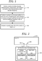
- FIG. 1 illustrates a method of estimating quality factor (Q) of a reverberant cavity that may be simple or complex.
- the cavity's interior surfaces reflect electromagnetic waves and exhibit resonance or resonant behaviour at resonant frequencies.
- the term "resonant mode bandwidth" refers to frequency separation between independent modes.
- a cavity is excited by signals having multiple discrete electromagnetic frequencies that are separated by a constant frequency step ( ⁇ f).
- ⁇ f constant frequency step
- an excitation signal is applied and removed, and the resulting electromagnetic field is allowed to decay before moving on to the next frequency.
- the frequencies may be increased sequentially. That is, the cavity may be excited by the following sequences of frequencies: f start , f start + ⁇ f, f start +2 ⁇ f, f start +3Af, ... f end . , where f start and f end are the starting and ending excitation frequencies.
- the smallest dimension of the cavity is more than one wavelength.
- the value of ⁇ f may be at least 10 times smaller than estimated resonant mode bandwidth of the cavity. As will be seen below, a ⁇ f that is 100 times smaller will result in a higher resolution estimate of Q than a ⁇ f that is 10 times smaller.
- measurements that characterize the electromagnetic field in the cavity are taken and stored.
- field characterization measurements include, but are not limited to, measurements of power, voltage, current and impedance. Each measurement may be taken after the field has built up and reached steady state. After f end has been measured and stored, there is data set of field characterization measurements corresponding to different discrete frequencies.
- a number (n) of circular shifts is performed on the data set by the frequency step ( ⁇ f), and a covariance-based coefficient is computed at each shift until the coefficient indicates a lack of correlation.
- the lack of correlation indicates the difference between the shifted data set and when compared to the original data set.
- the covariance-based coefficient may be a correlation coefficient. In some instances, the covariance-based coefficient may be a Pearson product-moment correlation coefficient.
- the lack of correlation may be determined by comparing the coefficient to a threshold. As but one example, the shifts are performed until the coefficient is less than (1/e).
- a quality factor (Q) of the reverberant cavity is computed as fc/( ⁇ f x n).
- the product ( ⁇ f x n) is equivalent to the resonant mode bandwidth.
- the resonant mode bandwidth indicates separation cavity modes in frequency.
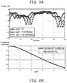
- FIG. 3A illustrates an example of an original data set of power measurements at discrete frequencies.
- the data set includes a total of 100 samples.
- Unshifted samples i.e., samples of the original data set
- circles ( ⁇ ) are denoted by circles ( ⁇ ).
- FIG. 3A illustrates a left circular shift
- a right circular shift may be used instead.
- FIG. 3B illustrates correlation of the shifted data sets to the original data set.
- Q fc/(350KHz).
- This example uses a 50 KHz frequency step. Had a smaller step been used (e.g., 5 KHz), between 60 and 70 shifts would have been performed, but the resolution of the estimate would have been higher, and the lack of correlation would have been indicated closer to 60 than 70.
- the excitation may be transmitted and measurements taken by one or more antennas in the cavity.
- measurements may be taken at a single location.
- multiple measurements may be taken at different locations in the cavity.
- the method of FIG. 1 provides a simple way of estimating Q of a cavity that is extremely difficult to model mathematically. There is no need to compute geometry volume or surface area, or estimate losses.
- the method can estimate Q for cavities having complex shapes and properties (e.g., walls made of different materials and thickness, coupling that is difficult to measure, loss mechanisms that are dynamic, apertures varying in size and space, etc.
- FIG. 2 illustrates a reverberant cavity 210 including a first antenna 220 and a second antenna 230 at a location inside the cavity 210.
- Each antenna 220 and 230 can transmit and receive.
- the antennas 220 and 230 may be arbitrarily located, but it is preferred that the line of sight component connecting the two antennas 220 and 230 is eliminated so that only multipath components are efficiently coupled.
- directional antennas may be pointed away from each other with cross-align polarity so that they are orthogonal (90 degrees).
- Ports 1 and 2 of a network analysis machine 240 may be coupled to the antennas 220 and 230.
- the network analysis machine 240 may include a signal generator 242, a test set 244, one or more receivers 246, and a processor 248.
- the signal generator 242 generates signals having multiple discrete frequencies, and the test set 244 routes the signals from the signal generator 242 to ports 1 and 2.
- the test set 244 also routes the received signals from ports1 and 2 to the receivers 246.
- the receiver 246 measures transmitted energy.
- the processor 248 creates the data set and computes Q according to blocks 120 and 130 of FIG. 1 .
- the machine 240 may measure s-parameters at each frequency step by (1) transmitting and then receiving with the first antenna 220; (2) transmitting with the first antenna 220 and receiving with the second antenna 230; (3) transmitting with the second antenna 230 and receiving with the first antenna 220; (4) transmitting and then receiving with the second antenna 230; then (5) computing the s-parameter coefficients S 11 , S 12 , S 21 , and S 22 ; and (6) computing the power at each discrete frequency step based on the transmission coefficient S 21 for gain/loss.
- power may be computed as (
- the network analysis machine 240 may be a commercial off-the-shelf network analyzer that generates s-parameters in a conventional manner, but is modified to perform the functions at block 120 and 130. However, the network analysis machine 240 is not limited to a network analyzer. As a first example the network analysis machine 240 may be a received signal strength indicator (RSSI) that is modified to perform the functions at blocks 120 and 130. The modified RSSI can compute Q in addition to computing signal strength at a location in a wireless network.
- RSSI received signal strength indicator
- the network analysis machine 240 may include a signal generator for generating test signals, and a spectrum analyzer or field probe for analyzing the responses and also performing the functions at block 120 and 130.
- the 2-port network analysis machine 240 of FIG. 2 may be used to estimate Q of a simple cavity in which fields are uniformly distributed.
- the network analysis machine 240 may estimate Q between port 2 and port 1. Since the cavity has a simple geometry, the port 2 antenna may be located anywhere within the cavity, and the same Q will be estimated. (Analysis of the simple cavity may instead by performed by a one-port machine with a single antenna and time gating to isolate the transmit signal and receive signals.)
- the 2-port network analysis machine 240 of FIG. 2 may also be used to estimate Q of a complex cavity in which the electromagnetic fields are not uniformly distributed. For complex cavities in which Q varies spatially, multiple measurements may be taken at different locations in the cavity. The port 2 antenna may be moved to multiple locations, and the functions of blocks 110-130 are performed at each location.
- an n-port analysis machine may be used, where n>3. All n antennas may be placed in different areas of interest within the complex cavity. A higher resolution estimate of Q as a whole may be computed since spatial sampling is being increased. For instance, Q34 could be the Q as estimated from transmitting from port 4 and receiving into port 3, and so on.
- the method of FIG. 1 is not limited to performing circular shifts on the entire data set. Segments of the discrete frequency bandwidth measurements may instead be used for circular shifting. For example, the entire data set contains power measurements taken over f start to f end at steps of ⁇ f. However, only a certain frequency is of interest. To estimate Q at the frequency of interest, a segment size might be 5% of the entire data set, with the frequency of interest at the center of the segment.
- FIG. 4 illustrates a method of using segments of an entire data set to select a wireless system for operation within a cavity.
- Two wireless systems are considered: an RFID system having a carrier frequency at 915 MHz, and a WiFi system having a carrier frequency of 2.45 GHz.
- a data set of field characterization measurements corresponding to different discrete frequencies is obtained for the cavity.
- Q of a segment centered at a first frequency of interest is estimated.
- Q of a segment centered at a second frequency of interest is estimated.
- a system is selected according to the comparison of the estimated Qs. Moreover, the selected system may be configured according to its estimated Q.
- the method of FIG. 1 may be used to estimate Q of a simple reverberant cavity.
- the power of the method of FIG. 1 lies with its ability to estimate Q for complex cavities.
- the complex cavity may be difficult to characterize in terms of true volume, it may have loss mechanisms that are difficult to estimate (e.g., due to mixed or unknown material types, leakage through apertures), and it may couple into neighbouring environments such as adjacent cavities and semi-enclosed volumes.
- Q of the complex cavity may vary spatially.
- FIG. 1 The method of FIG. 1 is not limited to any particular type of structure having a complex cavity. Examples of three structures will now be described.
- the first and second examples are aircraft structures.
- a large (e.g., commercial) aircraft includes a variety of structures having arbitrary shapes or partitions within larger cavities that are difficult to characterize in terms of true volume.
- FIG. 5 is an illustration of an aircraft 500 including aircraft structures with reverberant cavities having different geometry and composition.
- the composition could include metal (e.g., aluminum, titanium, alloys thereof), composite material (e.g., carbon fiber reinforced plastic), or other electrically conductive material.
- the aircraft structures include wings 510.
- Each wing 510 includes ribs, spars, stringers and skin panels that form a wing box.
- the ribs form partitioned cavities within the wing box.
- Each partitioned cavity may have minimum dimensions of one or more wavelengths in the frequency of interest. Volume of the partitioned cavities decreases from root to tip. Shapes of the partitioned cavities may change from root to tip of the wing 510. Electromagnetic coupling between the partitioned cavities may be unknown or very difficult to measure.
- Loss mechanisms may include resistive losses mostly in surfaces.
- the wing box cavity may contain dynamic loss mechanisms.
- the wing box cavity may form a fuel tank. As fuel is consumed during flight, the level of the fuel in the tank changes. The fuel itself has some loss.
- the shape of the wings 510 may change during flight.
- the wings 510 can flex during flight, which can change the geometry of and coupling between the partitioned cavities.
- the estimation of Q according to the method of FIG. 1 can account for these dynamics.
- Q may vary spatially within a wing box cavity.
- the method of FIG. 1 can be used to estimate Q at one or more partitioned cavities.
- the aircraft structures also includes a fuselage 520 made of frame members, floor beams, stiffeners and skin. These elements also form a large reverberant cavity that is partitioned into smaller cavities, such as the aircraft cabin, cockpit, galley, electrical equipment bay, and cargo compartment.
- the aircraft cabin for instance, includes loss mechanisms including, but not limited to, apertures for windows and doors, seats, people, and wireless device antennas that absorb energy. Many of these losses are dynamic: people move within the fuselage, doors are opened and closed, and wireless devices are switched on and off.
- the aircraft cabin may be electromagnetically coupled to some of the other partitioned cavities.
- the method of FIG. 1 can be used to estimate Q within the aircraft cabin. It may also be used to estimate Q within any of the other partitioned cavities in the fuselage 520.
- the aircraft 500 further includes a plurality of radiating elements 530 for transmitting excitation frequencies and receiving reverberant energy.
- the aircraft 500 further includes avionics 540.
- the avionics 540 may be located in electrical equipment (EE) Bay.
- the avionics 540 may utilize the method of FIG. 1 to perform real time estimation of Q in the aircraft.
- the avionics continuously estimates Q of each of the partitioned cavities within the wings 510 and fuselage 520 in real time.
- the avionics takes actions in response to changes in estimated Q.
- Q of a fuel tank is monitored.
- the fuel itself has some loss, so if all other things are equal, a wing 510 with an empty fuel tank has a higher Q than a wing 510 with a full tank.
- Q may be monitored during defuel and refuel and compared to known baselines of an empty tank and a full tank. Changes in Q during flight may be used to determine fuel level. Such monitoring of Q may be used as a back to a fuel quantity indication system (FQIS), or it may be used as a replacement for FQIS.
- FQIS fuel quantity indication system
- Q of the fuselage 520 may be monitored. Changes in Q may be used to detect doors opened and closed doors, and it may be used to detect people moving in and out of the fuselage 520.
- real-time estimation and monitoring of Q may be used to check structural health of the aircraft 500.
- Structural anomalies or defects e.g., large holes
- These changes may be used to monitor structural health. Flight or ground crews may be alerted as to changes in the structural health.
- Q-based structural health monitoring may be performed on aircraft structures that are used to enhance wireless data communication as described in the assignee's U.S. Patent No. 8,026,857 .
- the '857 patent describes wireless buses that use cavities as waveguides or resonators to propagate data and power. If a cavity is being used to propagate power or a signal, Q of that cavity may be monitored.
- aircraft structures 550 that may be used to propagate power or signal includes, without limitation, environmental control system (ECS) ducts, tubes of fuel and hydraulics systems, and nacelles and pylons of propulsion systems. Changes in Q of these structures may be monitored.
- ECS environmental control system
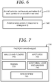
- FIG. 7 illustrates a different type of structure having a complex cavity: a factory warehouse 700.
- the factory warehouse 700 has walls and floors 710 of different materials and thickness.
- the factory warehouse 700 has different rooms (partitioned cavities) 720, which may be electromagnetically coupled.
- the factory warehouse 700 also has apertures 730 such as doors and windows, which are opened and closed.
- the factory warehouse 700 also contains objects of different sizes and materials, which provide additional loss mechanisms 740. Some of these objects (people, carts) are mobile within the factory warehouse. Other objects, such as large tools, might be stationary but change configuration during operation. Thus, Q of the factory warehouse 700 is difficult to measure due to mixed or unknown material types, leakage through apertures, coupling into neighbouring environments, movement of loss mechanisms, etc.
- the RFID system 750 is being proposed for the factory warehouse 700.
- the RFID system 750 will includes tags and readers for keeping track of assets (e.g., tools, materials, products) within the factory warehouse 700.
- assets e.g., tools, materials, products
- the readers will be placed at various locations in the warehouse 700, and the tags will be secured to the assets.
- Estimates of Q may be taken for different frequencies of interest, and the estimates may be taken at different locations in the warehouse 700. These estimates may be used to design and integrate the RFID system 750. For example, the Q may suggest how many readers are needed. A higher Q may suggest that fewer readers are needed since coverage zone is increased. Q may also be used to select locations of the readers.
- the Q may be used to select a carrier frequency, data rate and protocol. For example, a high Q cavity means energy is stored longer and that reflections can couple back into receiver and cause interference. If the data rate is very fast, the fields will not have adequate time to settle before the next symbol is transmitted, whereby interference occurs. Knowledge of Q may force the decision to lower the data rate of the system 750 or increase its sophistication to handle late time reflections.
Landscapes
- Engineering & Computer Science (AREA)
- Physics & Mathematics (AREA)
- General Physics & Mathematics (AREA)
- Mathematical Physics (AREA)
- Theoretical Computer Science (AREA)
- Data Mining & Analysis (AREA)
- Quality & Reliability (AREA)
- Power Engineering (AREA)
- Signal Processing (AREA)
- Computer Networks & Wireless Communication (AREA)
- Electromagnetism (AREA)
- Databases & Information Systems (AREA)
- General Engineering & Computer Science (AREA)
- Computational Mathematics (AREA)
- Software Systems (AREA)
- Algebra (AREA)
- Mathematical Optimization (AREA)
- Pure & Applied Mathematics (AREA)
- Mathematical Analysis (AREA)
- Arrangements For Transmission Of Measured Signals (AREA)
- Measurement Of Mechanical Vibrations Or Ultrasonic Waves (AREA)
Claims (15)
- Verfahren, das beinhaltet:Sammeln eines Datensatzes von Feldkennzeichnungsmessungen an einem Ort in einem hallenden Hohlraum (210), der durch Signale mit mehreren diskreten elektromagnetischen Frequenzen erregt wird, wobei die mehreren diskreten elektromagnetischen Frequenzen um einen konstanten Frequenzschritt (Δf) getrennt sind, wobei bei jeder diskreten elektromagnetischen Frequenz ein Erregungssignal angelegt und entfernt wird, und ein resultierendes elektromagnetisches Feld zerfallen kann, bevor es sich zu der nächsten diskreten elektromagnetischen Frequenz weiterbewegt, und wobei die Feldkennzeichnungsmessungen das elektromagnetische Feld in dem Hohlraum kennzeichnen;Durchführen einer Anzahl (n) zirkularer Verschiebungen um den konstanten Frequenzschritt (Δf) für den Datensatz und Berechnen eines kovarianzbasierten Koeffizienten bei jeder Verschiebung, bis der Koeffizient einen Korrelationsmangel zwischen einem verschobenen Datensatz und dem Datensatz anzeigt; undBerechnen eines Qualitätsfaktors (Q) des hallenden Hohlraums (210) als fc/(Δf x n), wobei fc eine Mittenfrequenz des Datensatzes ist.
- Verfahren nach Anspruch 1, wobei das Sammeln des Datensatzes das Messen von s-Parametern an dem Ort und das Berechnen von Leistungsmessungen basierend auf einem Übertragungskoeffizienten S21 beinhaltet.
- Verfahren nach Anspruch 1 oder 2, wobei der kovarianzbasierte Koeffizient ein Korrelationskoeffizient ist.
- Verfahren nach einem der Ansprüche 1 bis 3, wobei der kovarianzbasierte Koeffizient ein Pearson Produkt-Moment-Korrelationskoeffizient ist.
- Verfahren nach einem der Ansprüche 1 bis 4, wobei die Verschiebungen durchgeführt werden, bis der Koeffizient kleiner als (1/e) ist.
- Verfahren nach einem der Ansprüche 1 bis 5, wobei der konstante Frequenzschritt (Δf) kleiner als eine Resonanzmodenbandbreite des Hohlraums (210) ist.
- Verfahren nach einem der Ansprüche 1 bis 6, wobei das Sammeln des Datensatzes das Analysieren des hallenden Hohlraums (210) mit einer n-Port-Netzwerkanalysemaschine (240) beinhaltet.
- Verfahren nach einem der Ansprüche 1 bis 7, wobei das Sammeln des Datensatzes das Platzieren erster und zweiter Antennen (220 und 230) an dem Ort in dem Hohlraum (210) beinhaltet; und das Verwenden einer Netzwerkanalysemaschine (240), um Erregungssignale an die Antennen (220 und 230) anzulegen, und um Signale von den Antennen (220 und 230) zu empfangen, um den Datensatz zu berechnen, die zirkulären Verschiebungen durchzuführen und den Qualitätsfaktor zu berechnen.
- Verfahren nach einem der Ansprüche 1 bis 8, wobei zusätzliche Leistungsmessungen an zusätzlichen Orten in dem Hohlraum (210) durchgeführt werden und für jeden zusätzlichen Ort der korrespondierende Datensatz zirkular verschoben und Q berechnet wird.
- Verfahren nach einem der Ansprüche 1 bis 9, wobei zusätzliche Feldkennzeichnungsmessungen an zusätzlichen Antennenorten in dem Hohlraum (210) durchgeführt werden; und wobei Q für jeden der Orte berechnet wird.
- Verfahren nach einem der Ansprüche 1 bis 10, wobei die zirkularen Verschiebungen für ein Segment des Datensatzes durchgeführt werden, wobei das Segment bei einer interessierenden Frequenz zentriert ist; und wobei Q für das Segment geschätzt wird.
- Verfahren nach Anspruch 11, das des Weiteren das Schätzen von Q für ein Segment beinhaltet, das an einer anderen interessierenden Frequenz zentriert ist; und das Vergleichen der Qs der beiden Segmente; oder
wobei die unterschiedlichen interessierenden Frequenzen drahtlosen Systemen entsprechen, die unterschiedliche Trägerfrequenzen haben; und wobei eines der Systeme gemäß dem Vergleich der Qs ausgewählt wird. - Verfahren nach einem der Ansprüche 1 bis 11, wobei der Hohlraum (210) eine Vielzahl von Unterteilungen verschiedener Größe und unbekannter elektromagnetischer Kopplung aufweist.
- Verfahren nach Anspruch 13, wobei der Hohlraum (210) von einem Flugzeugflügel (510) gebildet wird, und wobei der Flügel eine Vielzahl dynamischer Verlustmechanismen (740) aufweist, wobei der Flügel dazu konfiguriert ist, Treibstoff zu lagern, wobei das Verfahren des Weiteren das Überwachen von Veränderungen des geschätzten Q beinhaltet, um den Treibstoffpegel zu bestimmen.
- Flugzeug (500) mit:einer Vielzahl von Strukturen mit komplexen Hohlräumen;einer Vielzahl von Antennen in den Hohlräumen, wobei die Antennen mit Ports einer Netzwerkanalysemaschine (240) verbunden sind; undFlugzeugavionik (540) zum Verwenden der Antennen (220 und 230), um die Hallräume mit Signalen zu erregen, die mehrere diskrete elektromagnetische Frequenzen haben, und um Datensätze von Feldkennzeichnungsmessungen für jeden Hohlraum (210) zu erhalten, wobei die mehreren diskreten elektromagnetischen Frequenzen um einen konstanten Frequenzschritt (Δf) getrennt sind, wobei bei jeder diskreten elektromagnetischen Frequenz ein Erregungssignal angelegt und entfernt wird, und ein resultierendes elektromagnetisches Feld zerfallen kann, bevor es sich zu der nächsten diskreten elektromagnetischen Frequenz weiterbewegt, und wobei die Feldkennzeichnungsmessungen das elektromagnetische Feld in dem Hallraum kennzeichnen, wobei ein Signalgenerator (242) dazu konfiguriert ist, die Signale zu erzeugen, ein Testsatz (244) dazu konfiguriert ist, die Signale von dem Signalgenerator an die Ports zu routen und die empfangenen Signale von den Ports an Empfänger (246) zu routen, wobei die Empfänger dazu konfiguriert sind, übertragene Energie zu messen, und wobei ein Prozessor (248) dazu konfiguriert ist, für jeden Ort des Hohlraums (210) eine Anzahl (n) zirkularer Verschiebungen um den konstanten Frequenzschritt (Δf) für den jeweiligen Datensatz durchzuführen und einen kovarianzbasierten Koeffizienten bei jeder Verschiebung zu berechnen, bis der Koeffizient einen Korrelationsmangel zwischen einem verschobenen Datensatz und dem jeweiligen Datensatz anzeigt; und einen Qualitätsfaktor (Q) an dem Ort als fc/(Δf x n) zu berechnen, wobei fc eine Mittenfrequenz des Datensatzes ist.
Applications Claiming Priority (1)
| Application Number | Priority Date | Filing Date | Title |
|---|---|---|---|
| US13/969,715 US10585971B2 (en) | 2013-08-19 | 2013-08-19 | Quality factor estimation of a reverberant cavity |
Publications (2)
| Publication Number | Publication Date |
|---|---|
| EP2840403A1 EP2840403A1 (de) | 2015-02-25 |
| EP2840403B1 true EP2840403B1 (de) | 2018-06-06 |
Family
ID=51539116
Family Applications (1)
| Application Number | Title | Priority Date | Filing Date |
|---|---|---|---|
| EP14180374.2A Active EP2840403B1 (de) | 2013-08-19 | 2014-08-08 | Qualitätsfaktor-Schätzung eines Hallraums |
Country Status (7)
| Country | Link |
|---|---|
| US (1) | US10585971B2 (de) |
| EP (1) | EP2840403B1 (de) |
| JP (1) | JP6375171B2 (de) |
| KR (1) | KR101952977B1 (de) |
| CN (1) | CN104426618B (de) |
| AU (1) | AU2014203123B2 (de) |
| BR (1) | BR102014020323A2 (de) |
Families Citing this family (6)
| Publication number | Priority date | Publication date | Assignee | Title |
|---|---|---|---|---|
| US10844794B2 (en) * | 2016-12-21 | 2020-11-24 | Delavan Inc. | Fuel quality monitoring systems |
| WO2018142995A1 (ja) * | 2017-01-31 | 2018-08-09 | パナソニックIpマネジメント株式会社 | 無線通信装置 |
| US10794841B2 (en) | 2018-05-07 | 2020-10-06 | Infineon Technologies Ag | Composite material structure monitoring system |
| CN109521079B (zh) * | 2018-11-20 | 2021-06-08 | 中电科思仪科技股份有限公司 | 一种多频点材料测试系统及方法 |
| CN110940711B (zh) * | 2019-12-10 | 2022-04-12 | 中国电子科技集团公司第四十六研究所 | 一种TE0delta模式频率和Q因子自动测试方法 |
| CN115392280B (zh) * | 2022-10-28 | 2023-03-24 | 华南理工大学 | 一种基于混响理论提高电子标签识别率的方法及系统 |
Family Cites Families (11)
| Publication number | Priority date | Publication date | Assignee | Title |
|---|---|---|---|---|
| US3506220A (en) * | 1968-04-11 | 1970-04-14 | Anthony Sbrilli | Horizontal axis,flat lifting rotor and control system for aircraft |
| US3506224A (en) * | 1968-12-04 | 1970-04-14 | Firestone Tire & Rubber Co | Supporting structure for a self-sealing fuel tank |
| US10674570B2 (en) | 2006-02-21 | 2020-06-02 | Goji Limited | System and method for applying electromagnetic energy |
| US7554339B2 (en) | 2006-12-01 | 2009-06-30 | The Boeing Company | Electromagnetic testing of an enclosure or cavity using a discrete frequency stir method |
| US8482298B2 (en) * | 2006-12-18 | 2013-07-09 | Schrader Electronics Ltd. | Liquid level and composition sensing systems and methods using EMF wave propagation |
| US7830523B2 (en) * | 2007-10-26 | 2010-11-09 | The Boeing Company | Nondestructive inspection of a structure including the analysis of cavity electromagnetic field response |
| US8026857B2 (en) | 2008-01-17 | 2011-09-27 | The Boeing Company | Wireless data communication and power transmission using aircraft structures having properties of an electromagnetic cavity |
| US8499631B2 (en) * | 2008-02-15 | 2013-08-06 | The Boeing Company | Nondestructive inspection of aircraft stiffeners |
| US8514921B2 (en) * | 2008-07-16 | 2013-08-20 | The Boeing Company | Assessing aircraft interference path loss employing discrete frequency stirring |
| US8085156B2 (en) * | 2009-04-08 | 2011-12-27 | Rosemount Inc. | RF cavity-based process fluid sensor |
| US8510065B2 (en) * | 2010-12-16 | 2013-08-13 | The Boeing Company | Wireless liquid quantity measurement system |
-
2013
- 2013-08-19 US US13/969,715 patent/US10585971B2/en active Active
-
2014
- 2014-06-10 AU AU2014203123A patent/AU2014203123B2/en active Active
- 2014-06-24 KR KR1020140077105A patent/KR101952977B1/ko active Active
- 2014-08-05 JP JP2014159117A patent/JP6375171B2/ja active Active
- 2014-08-08 EP EP14180374.2A patent/EP2840403B1/de active Active
- 2014-08-15 CN CN201410401344.3A patent/CN104426618B/zh active Active
- 2014-08-15 BR BR102014020323A patent/BR102014020323A2/pt not_active Application Discontinuation
Non-Patent Citations (1)
| Title |
|---|
| None * |
Also Published As
| Publication number | Publication date |
|---|---|
| KR101952977B1 (ko) | 2019-02-27 |
| BR102014020323A2 (pt) | 2015-11-24 |
| AU2014203123A1 (en) | 2015-03-05 |
| US20150051874A1 (en) | 2015-02-19 |
| AU2014203123B2 (en) | 2016-01-28 |
| US10585971B2 (en) | 2020-03-10 |
| CN104426618B (zh) | 2019-05-28 |
| JP2015045638A (ja) | 2015-03-12 |
| JP6375171B2 (ja) | 2018-08-15 |
| EP2840403A1 (de) | 2015-02-25 |
| KR20150020988A (ko) | 2015-02-27 |
| CN104426618A (zh) | 2015-03-18 |
Similar Documents
| Publication | Publication Date | Title |
|---|---|---|
| AU2014203123B2 (en) | Quality factor estimation of a reverberant cavity | |
| Semkin et al. | Analyzing radar cross section signatures of diverse drone models at mmWave frequencies | |
| CN106314822B (zh) | 飞机电磁环境安全裕度评估规程方法 | |
| JP5734971B2 (ja) | 無線信号のパワーハーベスティングによる無線検知のための方法および装置 | |
| EP2146441B1 (de) | Schätzung des Flugzeugs-Interferenz-Pfadeverlusts unter Verwendung diskreter Frequenzsteuerung | |
| Arboleya et al. | Millimeter and submillimeter planar measurement setup | |
| US20120235696A1 (en) | High frequency analysis of a device under test | |
| Alonso et al. | Towards a wireless battery management system: Evaluation of antennas and radio channel measurements inside a battery emulator | |
| Krutskikh et al. | Evaluation of the study of dielectric and metal-dielectric waveguides using digital twins under modern conditions | |
| EP3459862A1 (de) | Flugzeugrumpfüberprüfungssystem | |
| Gradoni et al. | Determination of the reverberation chamber stirrer uncorrelated positions by means of the spatial and frequency correlation matrix | |
| Jilani et al. | Equivalent circuit modeling of the dielectric loaded microwave biosensor | |
| Schaffar et al. | Application of the Power balance method to E field calculation in the Ariane 5 launcher payloads cavities | |
| Sadou et al. | Predictors generation by partial least square regression for microwave characterization of dielectric materials | |
| Knisely et al. | Uniaxial anisotropic material measurement using a single port waveguide probe | |
| Hikage et al. | Numerical analysis of electromagnetic field distributions in a typical aircraft | |
| Perrin et al. | Study of electric field radiated by WiFi sources inside an aircraft-3D computations and real tests | |
| Bommer et al. | Efficient measurement of aircraft quality factor for evaluation and prototyping of wireless systems | |
| Hu et al. | Measurement and Simulation of AeroMACS Signal Coverage for Airplane | |
| Schwark et al. | VHF interference measurements on cable harnesses in passenger cabins of airplanes | |
| Van't Hof et al. | Dispersion in the enclosed-space radio channel: Measurements and model | |
| Pairon et al. | Efficient Evaluation of Energy Focusing Based on Eigen-Beamforming | |
| Notaroš | Higher Order Computational Electromagnetics, Uncertainty Quantification, and Meshing Techniques with Applications in Wireless Communication, Medicine, and Meteorology | |
| Hislop et al. | Permittivity measurement under free space propagation | |
| Van't Hof et al. | Characterizing dispersion in the enclosed-space radio channel using a composite mode model |
Legal Events
| Date | Code | Title | Description |
|---|---|---|---|
| PUAI | Public reference made under article 153(3) epc to a published international application that has entered the european phase |
Free format text: ORIGINAL CODE: 0009012 |
|
| 17P | Request for examination filed |
Effective date: 20140808 |
|
| AK | Designated contracting states |
Kind code of ref document: A1 Designated state(s): AL AT BE BG CH CY CZ DE DK EE ES FI FR GB GR HR HU IE IS IT LI LT LU LV MC MK MT NL NO PL PT RO RS SE SI SK SM TR |
|
| AX | Request for extension of the european patent |
Extension state: BA ME |
|
| 17Q | First examination report despatched |
Effective date: 20170926 |
|
| GRAP | Despatch of communication of intention to grant a patent |
Free format text: ORIGINAL CODE: EPIDOSNIGR1 |
|
| INTG | Intention to grant announced |
Effective date: 20180201 |
|
| GRAS | Grant fee paid |
Free format text: ORIGINAL CODE: EPIDOSNIGR3 |
|
| GRAA | (expected) grant |
Free format text: ORIGINAL CODE: 0009210 |
|
| AK | Designated contracting states |
Kind code of ref document: B1 Designated state(s): AL AT BE BG CH CY CZ DE DK EE ES FI FR GB GR HR HU IE IS IT LI LT LU LV MC MK MT NL NO PL PT RO RS SE SI SK SM TR |
|
| REG | Reference to a national code |
Ref country code: GB Ref legal event code: FG4D |
|
| REG | Reference to a national code |
Ref country code: CH Ref legal event code: EP Ref country code: AT Ref legal event code: REF Ref document number: 1006695 Country of ref document: AT Kind code of ref document: T Effective date: 20180615 |
|
| REG | Reference to a national code |
Ref country code: IE Ref legal event code: FG4D |
|
| REG | Reference to a national code |
Ref country code: DE Ref legal event code: R096 Ref document number: 602014026573 Country of ref document: DE |
|
| REG | Reference to a national code |
Ref country code: FR Ref legal event code: PLFP Year of fee payment: 5 |
|
| REG | Reference to a national code |
Ref country code: NL Ref legal event code: MP Effective date: 20180606 |
|
| REG | Reference to a national code |
Ref country code: LT Ref legal event code: MG4D |
|
| PG25 | Lapsed in a contracting state [announced via postgrant information from national office to epo] |
Ref country code: ES Free format text: LAPSE BECAUSE OF FAILURE TO SUBMIT A TRANSLATION OF THE DESCRIPTION OR TO PAY THE FEE WITHIN THE PRESCRIBED TIME-LIMIT Effective date: 20180606 Ref country code: CY Free format text: LAPSE BECAUSE OF FAILURE TO SUBMIT A TRANSLATION OF THE DESCRIPTION OR TO PAY THE FEE WITHIN THE PRESCRIBED TIME-LIMIT Effective date: 20180606 Ref country code: LT Free format text: LAPSE BECAUSE OF FAILURE TO SUBMIT A TRANSLATION OF THE DESCRIPTION OR TO PAY THE FEE WITHIN THE PRESCRIBED TIME-LIMIT Effective date: 20180606 Ref country code: FI Free format text: LAPSE BECAUSE OF FAILURE TO SUBMIT A TRANSLATION OF THE DESCRIPTION OR TO PAY THE FEE WITHIN THE PRESCRIBED TIME-LIMIT Effective date: 20180606 Ref country code: BG Free format text: LAPSE BECAUSE OF FAILURE TO SUBMIT A TRANSLATION OF THE DESCRIPTION OR TO PAY THE FEE WITHIN THE PRESCRIBED TIME-LIMIT Effective date: 20180906 Ref country code: NO Free format text: LAPSE BECAUSE OF FAILURE TO SUBMIT A TRANSLATION OF THE DESCRIPTION OR TO PAY THE FEE WITHIN THE PRESCRIBED TIME-LIMIT Effective date: 20180906 Ref country code: SE Free format text: LAPSE BECAUSE OF FAILURE TO SUBMIT A TRANSLATION OF THE DESCRIPTION OR TO PAY THE FEE WITHIN THE PRESCRIBED TIME-LIMIT Effective date: 20180606 |
|
| PG25 | Lapsed in a contracting state [announced via postgrant information from national office to epo] |
Ref country code: GR Free format text: LAPSE BECAUSE OF FAILURE TO SUBMIT A TRANSLATION OF THE DESCRIPTION OR TO PAY THE FEE WITHIN THE PRESCRIBED TIME-LIMIT Effective date: 20180907 Ref country code: HR Free format text: LAPSE BECAUSE OF FAILURE TO SUBMIT A TRANSLATION OF THE DESCRIPTION OR TO PAY THE FEE WITHIN THE PRESCRIBED TIME-LIMIT Effective date: 20180606 Ref country code: RS Free format text: LAPSE BECAUSE OF FAILURE TO SUBMIT A TRANSLATION OF THE DESCRIPTION OR TO PAY THE FEE WITHIN THE PRESCRIBED TIME-LIMIT Effective date: 20180606 Ref country code: LV Free format text: LAPSE BECAUSE OF FAILURE TO SUBMIT A TRANSLATION OF THE DESCRIPTION OR TO PAY THE FEE WITHIN THE PRESCRIBED TIME-LIMIT Effective date: 20180606 |
|
| REG | Reference to a national code |
Ref country code: AT Ref legal event code: MK05 Ref document number: 1006695 Country of ref document: AT Kind code of ref document: T Effective date: 20180606 |
|
| PG25 | Lapsed in a contracting state [announced via postgrant information from national office to epo] |
Ref country code: NL Free format text: LAPSE BECAUSE OF FAILURE TO SUBMIT A TRANSLATION OF THE DESCRIPTION OR TO PAY THE FEE WITHIN THE PRESCRIBED TIME-LIMIT Effective date: 20180606 |
|
| PG25 | Lapsed in a contracting state [announced via postgrant information from national office to epo] |
Ref country code: RO Free format text: LAPSE BECAUSE OF FAILURE TO SUBMIT A TRANSLATION OF THE DESCRIPTION OR TO PAY THE FEE WITHIN THE PRESCRIBED TIME-LIMIT Effective date: 20180606 Ref country code: SK Free format text: LAPSE BECAUSE OF FAILURE TO SUBMIT A TRANSLATION OF THE DESCRIPTION OR TO PAY THE FEE WITHIN THE PRESCRIBED TIME-LIMIT Effective date: 20180606 Ref country code: CZ Free format text: LAPSE BECAUSE OF FAILURE TO SUBMIT A TRANSLATION OF THE DESCRIPTION OR TO PAY THE FEE WITHIN THE PRESCRIBED TIME-LIMIT Effective date: 20180606 Ref country code: PL Free format text: LAPSE BECAUSE OF FAILURE TO SUBMIT A TRANSLATION OF THE DESCRIPTION OR TO PAY THE FEE WITHIN THE PRESCRIBED TIME-LIMIT Effective date: 20180606 Ref country code: AT Free format text: LAPSE BECAUSE OF FAILURE TO SUBMIT A TRANSLATION OF THE DESCRIPTION OR TO PAY THE FEE WITHIN THE PRESCRIBED TIME-LIMIT Effective date: 20180606 Ref country code: IS Free format text: LAPSE BECAUSE OF FAILURE TO SUBMIT A TRANSLATION OF THE DESCRIPTION OR TO PAY THE FEE WITHIN THE PRESCRIBED TIME-LIMIT Effective date: 20181006 Ref country code: EE Free format text: LAPSE BECAUSE OF FAILURE TO SUBMIT A TRANSLATION OF THE DESCRIPTION OR TO PAY THE FEE WITHIN THE PRESCRIBED TIME-LIMIT Effective date: 20180606 |
|
| PG25 | Lapsed in a contracting state [announced via postgrant information from national office to epo] |
Ref country code: IT Free format text: LAPSE BECAUSE OF FAILURE TO SUBMIT A TRANSLATION OF THE DESCRIPTION OR TO PAY THE FEE WITHIN THE PRESCRIBED TIME-LIMIT Effective date: 20180606 Ref country code: SM Free format text: LAPSE BECAUSE OF FAILURE TO SUBMIT A TRANSLATION OF THE DESCRIPTION OR TO PAY THE FEE WITHIN THE PRESCRIBED TIME-LIMIT Effective date: 20180606 |
|
| REG | Reference to a national code |
Ref country code: DE Ref legal event code: R097 Ref document number: 602014026573 Country of ref document: DE |
|
| PG25 | Lapsed in a contracting state [announced via postgrant information from national office to epo] |
Ref country code: MC Free format text: LAPSE BECAUSE OF FAILURE TO SUBMIT A TRANSLATION OF THE DESCRIPTION OR TO PAY THE FEE WITHIN THE PRESCRIBED TIME-LIMIT Effective date: 20180606 |
|
| REG | Reference to a national code |
Ref country code: CH Ref legal event code: PL |
|
| PLBE | No opposition filed within time limit |
Free format text: ORIGINAL CODE: 0009261 |
|
| STAA | Information on the status of an ep patent application or granted ep patent |
Free format text: STATUS: NO OPPOSITION FILED WITHIN TIME LIMIT |
|
| PG25 | Lapsed in a contracting state [announced via postgrant information from national office to epo] |
Ref country code: LI Free format text: LAPSE BECAUSE OF NON-PAYMENT OF DUE FEES Effective date: 20180831 Ref country code: CH Free format text: LAPSE BECAUSE OF NON-PAYMENT OF DUE FEES Effective date: 20180831 Ref country code: LU Free format text: LAPSE BECAUSE OF NON-PAYMENT OF DUE FEES Effective date: 20180808 |
|
| REG | Reference to a national code |
Ref country code: BE Ref legal event code: MM Effective date: 20180831 |
|
| 26N | No opposition filed |
Effective date: 20190307 |
|
| REG | Reference to a national code |
Ref country code: IE Ref legal event code: MM4A |
|
| PG25 | Lapsed in a contracting state [announced via postgrant information from national office to epo] |
Ref country code: DK Free format text: LAPSE BECAUSE OF FAILURE TO SUBMIT A TRANSLATION OF THE DESCRIPTION OR TO PAY THE FEE WITHIN THE PRESCRIBED TIME-LIMIT Effective date: 20180606 Ref country code: SI Free format text: LAPSE BECAUSE OF FAILURE TO SUBMIT A TRANSLATION OF THE DESCRIPTION OR TO PAY THE FEE WITHIN THE PRESCRIBED TIME-LIMIT Effective date: 20180606 |
|
| PG25 | Lapsed in a contracting state [announced via postgrant information from national office to epo] |
Ref country code: IE Free format text: LAPSE BECAUSE OF NON-PAYMENT OF DUE FEES Effective date: 20180808 |
|
| PG25 | Lapsed in a contracting state [announced via postgrant information from national office to epo] |
Ref country code: BE Free format text: LAPSE BECAUSE OF NON-PAYMENT OF DUE FEES Effective date: 20180831 |
|
| PG25 | Lapsed in a contracting state [announced via postgrant information from national office to epo] |
Ref country code: AL Free format text: LAPSE BECAUSE OF FAILURE TO SUBMIT A TRANSLATION OF THE DESCRIPTION OR TO PAY THE FEE WITHIN THE PRESCRIBED TIME-LIMIT Effective date: 20180606 |
|
| PG25 | Lapsed in a contracting state [announced via postgrant information from national office to epo] |
Ref country code: MT Free format text: LAPSE BECAUSE OF NON-PAYMENT OF DUE FEES Effective date: 20180808 |
|
| PG25 | Lapsed in a contracting state [announced via postgrant information from national office to epo] |
Ref country code: TR Free format text: LAPSE BECAUSE OF FAILURE TO SUBMIT A TRANSLATION OF THE DESCRIPTION OR TO PAY THE FEE WITHIN THE PRESCRIBED TIME-LIMIT Effective date: 20180606 |
|
| PG25 | Lapsed in a contracting state [announced via postgrant information from national office to epo] |
Ref country code: HU Free format text: LAPSE BECAUSE OF FAILURE TO SUBMIT A TRANSLATION OF THE DESCRIPTION OR TO PAY THE FEE WITHIN THE PRESCRIBED TIME-LIMIT; INVALID AB INITIO Effective date: 20140808 Ref country code: PT Free format text: LAPSE BECAUSE OF FAILURE TO SUBMIT A TRANSLATION OF THE DESCRIPTION OR TO PAY THE FEE WITHIN THE PRESCRIBED TIME-LIMIT Effective date: 20180606 |
|
| PG25 | Lapsed in a contracting state [announced via postgrant information from national office to epo] |
Ref country code: MK Free format text: LAPSE BECAUSE OF NON-PAYMENT OF DUE FEES Effective date: 20180606 |
|
| P01 | Opt-out of the competence of the unified patent court (upc) registered |
Effective date: 20230516 |
|
| PGFP | Annual fee paid to national office [announced via postgrant information from national office to epo] |
Ref country code: DE Payment date: 20250827 Year of fee payment: 12 |
|
| PGFP | Annual fee paid to national office [announced via postgrant information from national office to epo] |
Ref country code: GB Payment date: 20250827 Year of fee payment: 12 |
|
| PGFP | Annual fee paid to national office [announced via postgrant information from national office to epo] |
Ref country code: FR Payment date: 20250825 Year of fee payment: 12 |