EP2840376A2 - Safety device for gas supply installation - Google Patents
Safety device for gas supply installation Download PDFInfo
- Publication number
- EP2840376A2 EP2840376A2 EP20120464006 EP12464006A EP2840376A2 EP 2840376 A2 EP2840376 A2 EP 2840376A2 EP 20120464006 EP20120464006 EP 20120464006 EP 12464006 A EP12464006 A EP 12464006A EP 2840376 A2 EP2840376 A2 EP 2840376A2
- Authority
- EP
- European Patent Office
- Prior art keywords
- gas
- installation
- building
- gas supply
- leakages
- Prior art date
- Legal status (The legal status is an assumption and is not a legal conclusion. Google has not performed a legal analysis and makes no representation as to the accuracy of the status listed.)
- Granted
Links
Images




Classifications
-
- G—PHYSICS
- G01—MEASURING; TESTING
- G01M—TESTING STATIC OR DYNAMIC BALANCE OF MACHINES OR STRUCTURES; TESTING OF STRUCTURES OR APPARATUS, NOT OTHERWISE PROVIDED FOR
- G01M3/00—Investigating fluid-tightness of structures
- G01M3/02—Investigating fluid-tightness of structures by using fluid or vacuum
- G01M3/04—Investigating fluid-tightness of structures by using fluid or vacuum by detecting the presence of fluid at the leakage point
- G01M3/20—Investigating fluid-tightness of structures by using fluid or vacuum by detecting the presence of fluid at the leakage point using special tracer materials, e.g. dye, fluorescent material, radioactive material
- G01M3/22—Investigating fluid-tightness of structures by using fluid or vacuum by detecting the presence of fluid at the leakage point using special tracer materials, e.g. dye, fluorescent material, radioactive material for pipes, cables or tubes; for pipe joints or seals; for valves; for welds; for containers, e.g. radiators
-
- F—MECHANICAL ENGINEERING; LIGHTING; HEATING; WEAPONS; BLASTING
- F17—STORING OR DISTRIBUTING GASES OR LIQUIDS
- F17C—VESSELS FOR CONTAINING OR STORING COMPRESSED, LIQUEFIED OR SOLIDIFIED GASES; FIXED-CAPACITY GAS-HOLDERS; FILLING VESSELS WITH, OR DISCHARGING FROM VESSELS, COMPRESSED, LIQUEFIED, OR SOLIDIFIED GASES
- F17C2205/00—Vessel construction, in particular mounting arrangements, attachments or identifications means
- F17C2205/01—Mounting arrangements
- F17C2205/0103—Exterior arrangements
-
- F—MECHANICAL ENGINEERING; LIGHTING; HEATING; WEAPONS; BLASTING
- F17—STORING OR DISTRIBUTING GASES OR LIQUIDS
- F17C—VESSELS FOR CONTAINING OR STORING COMPRESSED, LIQUEFIED OR SOLIDIFIED GASES; FIXED-CAPACITY GAS-HOLDERS; FILLING VESSELS WITH, OR DISCHARGING FROM VESSELS, COMPRESSED, LIQUEFIED, OR SOLIDIFIED GASES
- F17C2205/00—Vessel construction, in particular mounting arrangements, attachments or identifications means
- F17C2205/03—Fluid connections, filters, valves, closure means or other attachments
- F17C2205/0302—Fittings, valves, filters, or components in connection with the gas storage device
- F17C2205/0323—Valves
- F17C2205/0326—Valves electrically actuated
-
- F—MECHANICAL ENGINEERING; LIGHTING; HEATING; WEAPONS; BLASTING
- F17—STORING OR DISTRIBUTING GASES OR LIQUIDS
- F17C—VESSELS FOR CONTAINING OR STORING COMPRESSED, LIQUEFIED OR SOLIDIFIED GASES; FIXED-CAPACITY GAS-HOLDERS; FILLING VESSELS WITH, OR DISCHARGING FROM VESSELS, COMPRESSED, LIQUEFIED, OR SOLIDIFIED GASES
- F17C2250/00—Accessories; Control means; Indicating, measuring or monitoring of parameters
- F17C2250/03—Control means
- F17C2250/032—Control means using computers
-
- F—MECHANICAL ENGINEERING; LIGHTING; HEATING; WEAPONS; BLASTING
- F17—STORING OR DISTRIBUTING GASES OR LIQUIDS
- F17C—VESSELS FOR CONTAINING OR STORING COMPRESSED, LIQUEFIED OR SOLIDIFIED GASES; FIXED-CAPACITY GAS-HOLDERS; FILLING VESSELS WITH, OR DISCHARGING FROM VESSELS, COMPRESSED, LIQUEFIED, OR SOLIDIFIED GASES
- F17C2250/00—Accessories; Control means; Indicating, measuring or monitoring of parameters
- F17C2250/03—Control means
- F17C2250/036—Control means using alarms
-
- F—MECHANICAL ENGINEERING; LIGHTING; HEATING; WEAPONS; BLASTING
- F17—STORING OR DISTRIBUTING GASES OR LIQUIDS
- F17C—VESSELS FOR CONTAINING OR STORING COMPRESSED, LIQUEFIED OR SOLIDIFIED GASES; FIXED-CAPACITY GAS-HOLDERS; FILLING VESSELS WITH, OR DISCHARGING FROM VESSELS, COMPRESSED, LIQUEFIED, OR SOLIDIFIED GASES
- F17C2250/00—Accessories; Control means; Indicating, measuring or monitoring of parameters
- F17C2250/04—Indicating or measuring of parameters as input values
- F17C2250/0404—Parameters indicated or measured
- F17C2250/0465—Vibrations, e.g. of acoustic type
-
- F—MECHANICAL ENGINEERING; LIGHTING; HEATING; WEAPONS; BLASTING
- F17—STORING OR DISTRIBUTING GASES OR LIQUIDS
- F17C—VESSELS FOR CONTAINING OR STORING COMPRESSED, LIQUEFIED OR SOLIDIFIED GASES; FIXED-CAPACITY GAS-HOLDERS; FILLING VESSELS WITH, OR DISCHARGING FROM VESSELS, COMPRESSED, LIQUEFIED, OR SOLIDIFIED GASES
- F17C2260/00—Purposes of gas storage and gas handling
- F17C2260/03—Dealing with losses
- F17C2260/035—Dealing with losses of fluid
- F17C2260/036—Avoiding leaks
-
- F—MECHANICAL ENGINEERING; LIGHTING; HEATING; WEAPONS; BLASTING
- F17—STORING OR DISTRIBUTING GASES OR LIQUIDS
- F17C—VESSELS FOR CONTAINING OR STORING COMPRESSED, LIQUEFIED OR SOLIDIFIED GASES; FIXED-CAPACITY GAS-HOLDERS; FILLING VESSELS WITH, OR DISCHARGING FROM VESSELS, COMPRESSED, LIQUEFIED, OR SOLIDIFIED GASES
- F17C2260/00—Purposes of gas storage and gas handling
- F17C2260/04—Reducing risks and environmental impact
- F17C2260/042—Reducing risk of explosion
Definitions
- This invention is referred to a gas installation, mounted on masonry walls, composed by pipes of CuSn protected with an extensible P.P. tube, which has the role to collect eventual leaks from installation and transmit to a safety control panel.
- Safety control panel is composed by seism gas sensors which, by means of an electro-valve, shall cut-off gas supplying in case when eventual leakage occur.
- Gas installation mounted external or on masonry walls are well-known. All these are constructed by copper or drawn steel pipe, mounted by means of threaded fittings (such as elbows, tees, reductions) and valves. The valve is typical for gas, and for sealing a hemp or Teflon are used... Hemp comes lubricated with a special paste for avoid drying from gas circulated by pipes. Connections checking shall be done every two years, without a pressure test, and every ten years by means of a pressure test. Pipes passing by walls shall be done by a rigid tube having a role of protection for gas pipe. Pipes passing or crossing by shall be done upside the windows on 5 cm from ceiling, with interdiction to bury them. On consuming point vicinity shall be mounted an electrical gas sensor, connected on power supply, having the role of cutting-off gas supplying in case of room gas leakage.
- This safety device for a gas supply installation has the role of prevent from system's gas leakages accumulated in buildings, in order to avoid the risk of explosions, and asphyxiations.
- the safety device for gas supply installation shall overcome disadvantages shown above, because its purpose and quality is to control almost instantaneously the possible gas leakages of the masonry embedded system, by means of supplying by a copper pipe (soft) protected by an extensible tube of P.P.
- the copper pipe shall be without connections from distribution panel to the final gas consuming point.
- the safety device provides a earthquake gas sensor, electro-valve, allocator, and the safety panel located on distribution panel door provides signaling led (for functioning, damage, alarm), a reset button, a micro-switches group, checking button, and a identification label.
- This safety device for the masonry embedded gas supply system is the one that is going to control the possible leakages on the system's track and that is going to stop the building's gas supply system when the gas sensor shall detect such leakages.
- the device shall also stop the building's gas supply system in case of earthquakes too. This device makes the system safer and it allows the user to better control it.
- Each consuming point shall have a separate circuit and at the same time a controlled one.
- Figure 1 describes the building installation
- figure 2 describes a distribution panel
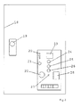
- Figure 3 describes the safety panel
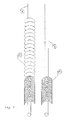
- Figure 4 describes the copper pipe of installation and protection and collection extensible tube of P.P.
- Figure 5 describes the wall section of supplying pipe
- protection tube describes a wall section from the consuming point side
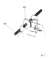
- Figure 7 describes welding method of extensible P.P. tube by means of thermal fusion.
- This safety device for gas supply installation is composed by distribution panel (9), tube for protection and gas collecting, extensible of P.P. (31, 32); this tube can be welded by thermal fusion with a welting device (42), for the case when a prolonging or recovery is necessary.
- a necklace shall be mounted (37) for protection P.P. tube squeezing (39) on the copper gas pipe (38), preventing eventual gas leakages, but merely direction them to the gas earthquake sensor (14).
- This sensor by a conductor (15) shall close the electro valve (11), cutting-off the gas supply in case of gas leakages.
- Earthquake gas sensor located in distribution panel (9) is powered directly from power network (16).
- Protection tube of P.P. (13) shall be mounted on the other side on the distribution panel (9), on a collar (12) with a bracelet for non permitting gas dispersion outside. Copper pipe connection on distribution panel and on consuming point shall be done by welding. In this way, an adaptor piece shall be welded on the copper pipe both sides, and this piece shall be a thread connection to the closing valve (40).
- Welding shall be done with a silvered copper wire, and a propane heater.
- the installation gas pressure after the regulator is of 0.5 bars, and for the copper pipe a pressure of 2 bars may be used.
- a pressure of 2 bars may be used for a gas leakage of 10% in environment.
- the sensor reaction immediately. This level of 10% of leakage is below danger limit, so explosion, or asphyxiation risk does not exist.
- Event tough a power surge when earthquake gas sensor (14) does not function, and electro valve (11) does not cut-off gas supply, eventual leakages shall be collected by extensible protection tube of P.P. (31, 32) and moved to distribution panel (9), and then outside the building, as the distribution panel was mounted inside the building. Leakages shall be evacuated always by protection P.P. tube (31, 32) providing protection on gas pipe (17) from distribution panel to the exterior of building for dispersion.
Landscapes
- Physics & Mathematics (AREA)
- General Physics & Mathematics (AREA)
- Filling Or Discharging Of Gas Storage Vessels (AREA)
- Protection Of Pipes Against Damage, Friction, And Corrosion (AREA)
- Pipeline Systems (AREA)
- Emergency Alarm Devices (AREA)
- Feeding And Controlling Fuel (AREA)
- Safety Valves (AREA)
Abstract
Description
- This invention is referred to a gas installation, mounted on masonry walls, composed by pipes of CuSn protected with an extensible P.P. tube, which has the role to collect eventual leaks from installation and transmit to a safety control panel. Safety control panel is composed by seism gas sensors which, by means of an electro-valve, shall cut-off gas supplying in case when eventual leakage occur.
- Gas installation mounted external or on masonry walls are well-known. All these are constructed by copper or drawn steel pipe, mounted by means of threaded fittings (such as elbows, tees, reductions) and valves. The valve is typical for gas, and for sealing a hemp or Teflon are used... Hemp comes lubricated with a special paste for avoid drying from gas circulated by pipes. Connections checking shall be done every two years, without a pressure test, and every ten years by means of a pressure test. Pipes passing by walls shall be done by a rigid tube having a role of protection for gas pipe. Pipes passing or crossing by shall be done upside the windows on 5 cm from ceiling, with interdiction to bury them. On consuming point vicinity shall be mounted an electrical gas sensor, connected on power supply, having the role of cutting-off gas supplying in case of room gas leakage.
- Disadvantages on this gas supply installation consist in a possible gas leakage of the installation on connections, due to the hemp drying during time. In case of gas leakage from installation, all these leakage cannot be controlled rapidly and instantly, as gas sensor would become inefficient, due to a possible power surge. A possibility for these gas leakages to be vented over the building does not exist; moreover gas accumulation is possible within building or on the masonry embedded system's track, without being able to control the possible gas leakage of the system. In case of earthquake, a steel pipe is moving from connections and consequently become a source for gas leakages. It does a great labor, as well as the unaesthetic character.
- This safety device for a gas supply installation has the role of prevent from system's gas leakages accumulated in buildings, in order to avoid the risk of explosions, and asphyxiations.
- According to this invention, the safety device for gas supply installation shall overcome disadvantages shown above, because its purpose and quality is to control almost instantaneously the possible gas leakages of the masonry embedded system, by means of supplying by a copper pipe (soft) protected by an extensible tube of P.P. The copper pipe shall be without connections from distribution panel to the final gas consuming point. The safety device provides a earthquake gas sensor, electro-valve, allocator, and the safety panel located on distribution panel door provides signaling led (for functioning, damage, alarm), a reset button, a micro-switches group, checking button, and a identification label.
- This safety device for the masonry embedded gas supply system is the one that is going to control the possible leakages on the system's track and that is going to stop the building's gas supply system when the gas sensor shall detect such leakages. The device shall also stop the building's gas supply system in case of earthquakes too. This device makes the system safer and it allows the user to better control it. Each consuming point shall have a separate circuit and at the same time a controlled one.
- This safety device for gas supply installation is presented in
Figures 1 ,2 ,3 , to7 . -
Figure 1 describes the building installation,figure 2 describes a distribution panel,Figure 3 describes the safety panel,Figure 4 describes the copper pipe of installation and protection and collection extensible tube of P.P.,Figure 5 describes the wall section of supplying pipe, and protection tube,Figure 6 describes a wall section from the consuming point side,Figure 7 describes welding method of extensible P.P. tube by means of thermal fusion. - This safety device for gas supply installation is composed by distribution panel (9), tube for protection and gas collecting, extensible of P.P. (31, 32); this tube can be welded by thermal fusion with a welting device (42), for the case when a prolonging or recovery is necessary. On the consuming point wall side, before the closing vent (40), a necklace shall be mounted (37) for protection P.P. tube squeezing (39) on the copper gas pipe (38), preventing eventual gas leakages, but merely direction them to the gas earthquake sensor (14). This sensor, by a conductor (15) shall close the electro valve (11), cutting-off the gas supply in case of gas leakages. Earthquake gas sensor located in distribution panel (9), is powered directly from power network (16). On the distribution panel door (18) a lock (19) and safety sensor panel are located. This panel is composed from test (20), checking button (21), earthquake gas sensor (22), identification label (23), green light led indicating a good function (24), yellow light led indicating damage (25), red light led indicating alarm (26), reset button (27) and a group of micro-switches (28). Protection tube of P.P. (13) shall be mounted on the other side on the distribution panel (9), on a collar (12) with a bracelet for non permitting gas dispersion outside. Copper pipe connection on distribution panel and on consuming point shall be done by welding. In this way, an adaptor piece shall be welded on the copper pipe both sides, and this piece shall be a thread connection to the closing valve (40). Welding shall be done with a silvered copper wire, and a propane heater. The installation gas pressure after the regulator is of 0.5 bars, and for the copper pipe a pressure of 2 bars may be used. For a gas leakage of 10% in environment, the sensor reaction immediately. This level of 10% of leakage is below danger limit, so explosion, or asphyxiation risk does not exist.
- Event tough a power surge, when earthquake gas sensor (14) does not function, and electro valve (11) does not cut-off gas supply, eventual leakages shall be collected by extensible protection tube of P.P. (31, 32) and moved to distribution panel (9), and then outside the building, as the distribution panel was mounted inside the building. Leakages shall be evacuated always by protection P.P. tube (31, 32) providing protection on gas pipe (17) from distribution panel to the exterior of building for dispersion.
Claims (3)
- The safety device for gas supply installation, within masonry wall, assure an eventual gas leakages collection, from buildings, and instantly cut-off gas supply of the said installation. Is composed from a distribution panel. This distribution panel is characterized in that is composed from a box (9), allocator (10), electro-valve (11), a collar for affixing protection tube (12), a earthquake gas sensor (14).
- The safety panel is located on distribution panel door and is characterized in that is composed by a test (20), checking button (21), identification label (23), led indicating for functioning, damage, alarm (24, 25, 26), reset button (27), a group of micro-switches (28).
- The extensible collecting and protection tube of P.P. (31, 32) for the copper pipe of the said installation (30, 33).
Priority Applications (3)
| Application Number | Priority Date | Filing Date | Title |
|---|---|---|---|
| PL12464006T PL2840376T3 (en) | 2011-05-04 | 2012-05-04 | Safety device for gas supply installation |
| SI201230853A SI2840376T1 (en) | 2011-05-04 | 2012-05-04 | Safety device for gas supply installation |
| HRP20170150TT HRP20170150T1 (en) | 2011-05-04 | 2017-01-31 | Safety device for gas supply installation |
Applications Claiming Priority (1)
| Application Number | Priority Date | Filing Date | Title |
|---|---|---|---|
| ROA201100416A RO126785B1 (en) | 2011-05-04 | 2011-05-04 | Gas supply installation embedded into masonry |
Publications (4)
| Publication Number | Publication Date |
|---|---|
| EP2840376A2 true EP2840376A2 (en) | 2015-02-25 |
| EP2840376A3 EP2840376A3 (en) | 2015-04-08 |
| EP2840376B1 EP2840376B1 (en) | 2016-11-02 |
| EP2840376B8 EP2840376B8 (en) | 2017-11-29 |
Family
ID=44837915
Family Applications (1)
| Application Number | Title | Priority Date | Filing Date |
|---|---|---|---|
| EP12464006.1A Active EP2840376B8 (en) | 2011-05-04 | 2012-05-04 | Safety device for gas supply installation |
Country Status (9)
| Country | Link |
|---|---|
| EP (1) | EP2840376B8 (en) |
| DK (1) | DK2840376T3 (en) |
| ES (1) | ES2613085T3 (en) |
| HR (1) | HRP20170150T1 (en) |
| HU (1) | HUE030775T2 (en) |
| LT (1) | LT2840376T (en) |
| PL (1) | PL2840376T3 (en) |
| RO (1) | RO126785B1 (en) |
| SI (1) | SI2840376T1 (en) |
Family Cites Families (3)
| Publication number | Priority date | Publication date | Assignee | Title |
|---|---|---|---|---|
| GB0110223D0 (en) * | 2001-04-26 | 2001-06-20 | Sensor Highway Ltd | Method and apparatus for leak detection and location |
| WO2006034724A1 (en) * | 2004-09-28 | 2006-04-06 | Gall & Seitz Gmbh | Double wall pipe |
| US20100212752A1 (en) * | 2009-02-23 | 2010-08-26 | Giovanni Fima | Shut Off Protection For Hot Water Heater |
-
2011
- 2011-05-04 RO ROA201100416A patent/RO126785B1/en unknown
-
2012
- 2012-05-04 LT LTEP12464006.1T patent/LT2840376T/en unknown
- 2012-05-04 SI SI201230853A patent/SI2840376T1/en unknown
- 2012-05-04 EP EP12464006.1A patent/EP2840376B8/en active Active
- 2012-05-04 DK DK12464006.1T patent/DK2840376T3/en active
- 2012-05-04 HU HUE12464006A patent/HUE030775T2/en unknown
- 2012-05-04 PL PL12464006T patent/PL2840376T3/en unknown
- 2012-05-04 ES ES12464006.1T patent/ES2613085T3/en active Active
-
2017
- 2017-01-31 HR HRP20170150TT patent/HRP20170150T1/en unknown
Non-Patent Citations (1)
| Title |
|---|
| None |
Also Published As
| Publication number | Publication date |
|---|---|
| RO126785A0 (en) | 2011-10-28 |
| EP2840376A3 (en) | 2015-04-08 |
| RO126785B1 (en) | 2014-06-30 |
| ES2613085T3 (en) | 2017-05-22 |
| SI2840376T1 (en) | 2017-03-31 |
| EP2840376B1 (en) | 2016-11-02 |
| EP2840376B8 (en) | 2017-11-29 |
| HRP20170150T1 (en) | 2017-03-24 |
| DK2840376T3 (en) | 2017-02-13 |
| PL2840376T3 (en) | 2017-05-31 |
| LT2840376T (en) | 2017-03-10 |
| HUE030775T2 (en) | 2017-06-28 |
Similar Documents
| Publication | Publication Date | Title |
|---|---|---|
| KR101453164B1 (en) | Remote firefighting checking system and method of the multi unit dwelling or building | |
| US20130255798A1 (en) | Wireless Automated Shutoff Valve | |
| CN201629021U (en) | Fireproof earth-leakage monitoring device | |
| CN103272359B (en) | A kind of real-time monitoring system for structural fire protection water supply system and method | |
| KR101701455B1 (en) | Remote fire fighting checking system of apartment house | |
| CN107575139A (en) | A kind of pipe gallery fire door control system and method | |
| CN102313436A (en) | Refrigerator and automatic fire alarm method thereof | |
| KR101291717B1 (en) | Fire equipment pressure control system | |
| KR20040076961A (en) | System for monitoring the gas pipe in remote | |
| CN107120044A (en) | A kind of underground power cable passage Fire-proof door device | |
| CN104658206A (en) | Novel community fire protection system | |
| CN207314437U (en) | A kind of fire hydrant water pressure monitoring device | |
| KR20150061289A (en) | Fire pathway prediction system based USN | |
| EP2840376A2 (en) | Safety device for gas supply installation | |
| KR20140013233A (en) | Fire disaster prevention devices of detecting a fire accident and a point source of light | |
| CN204143587U (en) | A kind of cable duct fire protection alarm device | |
| CN104373819B (en) | Monitoring device and monitoring method for prefabricated directly-buried thermal insulation pipe alarm line | |
| CN206581291U (en) | There is the natural gas piping lane of alarm pretreatment system | |
| KR20150061251A (en) | Fire service system based USN | |
| CN111273597A (en) | Centralized monitoring and inspection system for firefighting facilities | |
| CN206707567U (en) | A kind of underground power cable passage Fire-proof door device | |
| KR20240042296A (en) | Integrated monitoring and management system for fire hydrant with frost protection function | |
| CN202569267U (en) | Non-electric linear detection and fire-extinguishing system | |
| KR102126070B1 (en) | Fire detection and extinguishing systems | |
| CN105370999A (en) | Insulating pipe fitting comprising alarming lines and alarming method |
Legal Events
| Date | Code | Title | Description |
|---|---|---|---|
| PUAI | Public reference made under article 153(3) epc to a published international application that has entered the european phase |
Free format text: ORIGINAL CODE: 0009012 |
|
| 17P | Request for examination filed |
Effective date: 20120504 |
|
| AK | Designated contracting states |
Kind code of ref document: A2 Designated state(s): AL AT BE BG CH CY CZ DE DK EE ES FI FR GB GR HR HU IE IS IT LI LT LU LV MC MK MT NL NO PL PT RO RS SE SI SK SM TR |
|
| AX | Request for extension of the european patent |
Extension state: BA ME |
|
| PUAL | Search report despatched |
Free format text: ORIGINAL CODE: 0009013 |
|
| AK | Designated contracting states |
Kind code of ref document: A3 Designated state(s): AL AT BE BG CH CY CZ DE DK EE ES FI FR GB GR HR HU IE IS IT LI LT LU LV MC MK MT NL NO PL PT RO RS SE SI SK SM TR |
|
| AX | Request for extension of the european patent |
Extension state: BA ME |
|
| RIC1 | Information provided on ipc code assigned before grant |
Ipc: G01M 3/22 20060101AFI20150227BHEP |
|
| R17P | Request for examination filed (corrected) |
Effective date: 20150618 |
|
| 17Q | First examination report despatched |
Effective date: 20151022 |
|
| GRAP | Despatch of communication of intention to grant a patent |
Free format text: ORIGINAL CODE: EPIDOSNIGR1 |
|
| INTG | Intention to grant announced |
Effective date: 20160527 |
|
| GRAS | Grant fee paid |
Free format text: ORIGINAL CODE: EPIDOSNIGR3 |
|
| GRAA | (expected) grant |
Free format text: ORIGINAL CODE: 0009210 |
|
| AK | Designated contracting states |
Kind code of ref document: B1 Designated state(s): AL AT BE BG CH CY CZ DE DK EE ES FI FR GB GR HR HU IE IS IT LI LT LU LV MC MK MT NL NO PL PT RO RS SE SI SK SM TR |
|
| REG | Reference to a national code |
Ref country code: GB Ref legal event code: FG4D |
|
| REG | Reference to a national code |
Ref country code: AT Ref legal event code: REF Ref document number: 842323 Country of ref document: AT Kind code of ref document: T Effective date: 20161115 Ref country code: CH Ref legal event code: EP |
|
| REG | Reference to a national code |
Ref country code: IE Ref legal event code: FG4D |
|
| REG | Reference to a national code |
Ref country code: DE Ref legal event code: R096 Ref document number: 602012024792 Country of ref document: DE |
|
| REG | Reference to a national code |
Ref country code: HR Ref legal event code: TUEP Ref document number: P20170150 Country of ref document: HR |
|
| REG | Reference to a national code |
Ref country code: DK Ref legal event code: T3 Effective date: 20170208 |
|
| REG | Reference to a national code |
Ref country code: NL Ref legal event code: FP |
|
| PG25 | Lapsed in a contracting state [announced via postgrant information from national office to epo] |
Ref country code: LV Free format text: LAPSE BECAUSE OF FAILURE TO SUBMIT A TRANSLATION OF THE DESCRIPTION OR TO PAY THE FEE WITHIN THE PRESCRIBED TIME-LIMIT Effective date: 20161102 |
|
| REG | Reference to a national code |
Ref country code: CH Ref legal event code: NV Representative=s name: WAGNER + HELBIG PATENTANWAELTE CONSEILS EN PRO, CH Ref country code: SE Ref legal event code: TRGR |
|
| REG | Reference to a national code |
Ref country code: NO Ref legal event code: T2 Effective date: 20161102 |
|
| REG | Reference to a national code |
Ref country code: HR Ref legal event code: T1PR Ref document number: P20170150 Country of ref document: HR |
|
| REG | Reference to a national code |
Ref country code: HR Ref legal event code: ODRP Ref document number: P20170150 Country of ref document: HR Payment date: 20170426 Year of fee payment: 6 |
|
| PG25 | Lapsed in a contracting state [announced via postgrant information from national office to epo] |
Ref country code: GR Free format text: LAPSE BECAUSE OF FAILURE TO SUBMIT A TRANSLATION OF THE DESCRIPTION OR TO PAY THE FEE WITHIN THE PRESCRIBED TIME-LIMIT Effective date: 20170203 |
|
| REG | Reference to a national code |
Ref country code: FR Ref legal event code: PLFP Year of fee payment: 6 |
|
| REG | Reference to a national code |
Ref country code: ES Ref legal event code: FG2A Ref document number: 2613085 Country of ref document: ES Kind code of ref document: T3 Effective date: 20170522 |
|
| REG | Reference to a national code |
Ref country code: HU Ref legal event code: FH1C Free format text: FORMER REPRESENTATIVE(S): DANUBIA SZABADALMI ES JOGI IRODA KFT., HU Representative=s name: DANUBIA SZABADALAMI ES JOGI IRODA KFT., HU Ref country code: HU Ref legal event code: GB9C Owner name: TAMAS-SZORA ATTILA, RO Free format text: FORMER OWNER(S): TAMA-SZORA ATTILA, RO; TAMAS-SZORA GABRIEL, RO; BORSA, IOAN MARIUS, RO Ref country code: HU Ref legal event code: GB9C Owner name: TAMAS-SZORA GABRIEL, RO Free format text: FORMER OWNER(S): TAMA-SZORA ATTILA, RO; TAMAS-SZORA GABRIEL, RO; BORSA, IOAN MARIUS, RO |
|
| PG25 | Lapsed in a contracting state [announced via postgrant information from national office to epo] |
Ref country code: PT Free format text: LAPSE BECAUSE OF FAILURE TO SUBMIT A TRANSLATION OF THE DESCRIPTION OR TO PAY THE FEE WITHIN THE PRESCRIBED TIME-LIMIT Effective date: 20170302 Ref country code: RS Free format text: LAPSE BECAUSE OF FAILURE TO SUBMIT A TRANSLATION OF THE DESCRIPTION OR TO PAY THE FEE WITHIN THE PRESCRIBED TIME-LIMIT Effective date: 20161102 |
|
| REG | Reference to a national code |
Ref country code: HU Ref legal event code: AG4A Ref document number: E030775 Country of ref document: HU |
|
| PG25 | Lapsed in a contracting state [announced via postgrant information from national office to epo] |
Ref country code: RO Free format text: LAPSE BECAUSE OF FAILURE TO SUBMIT A TRANSLATION OF THE DESCRIPTION OR TO PAY THE FEE WITHIN THE PRESCRIBED TIME-LIMIT Effective date: 20161102 Ref country code: EE Free format text: LAPSE BECAUSE OF FAILURE TO SUBMIT A TRANSLATION OF THE DESCRIPTION OR TO PAY THE FEE WITHIN THE PRESCRIBED TIME-LIMIT Effective date: 20161102 |
|
| PGFP | Annual fee paid to national office [announced via postgrant information from national office to epo] |
Ref country code: MC Payment date: 20170530 Year of fee payment: 6 Ref country code: DK Payment date: 20170509 Year of fee payment: 6 Ref country code: SK Payment date: 20170502 Year of fee payment: 6 Ref country code: IE Payment date: 20170512 Year of fee payment: 6 Ref country code: HR Payment date: 20170426 Year of fee payment: 6 Ref country code: LT Payment date: 20170421 Year of fee payment: 6 Ref country code: CZ Payment date: 20170502 Year of fee payment: 6 Ref country code: IS Payment date: 20170511 Year of fee payment: 6 Ref country code: GB Payment date: 20170531 Year of fee payment: 6 |
|
| REG | Reference to a national code |
Ref country code: DE Ref legal event code: R097 Ref document number: 602012024792 Country of ref document: DE |
|
| PG25 | Lapsed in a contracting state [announced via postgrant information from national office to epo] |
Ref country code: SM Free format text: LAPSE BECAUSE OF FAILURE TO SUBMIT A TRANSLATION OF THE DESCRIPTION OR TO PAY THE FEE WITHIN THE PRESCRIBED TIME-LIMIT Effective date: 20161102 |
|
| PGFP | Annual fee paid to national office [announced via postgrant information from national office to epo] |
Ref country code: ES Payment date: 20170605 Year of fee payment: 6 Ref country code: FI Payment date: 20170516 Year of fee payment: 6 Ref country code: SE Payment date: 20170512 Year of fee payment: 6 Ref country code: PL Payment date: 20170427 Year of fee payment: 6 Ref country code: LU Payment date: 20170518 Year of fee payment: 6 |
|
| RAP2 | Party data changed (patent owner data changed or rights of a patent transferred) |
Owner name: BORSA, IOAN MARIUS Owner name: ALL GLOBAL MEDIA SRL |
|
| RIN2 | Information on inventor provided after grant (corrected) |
Inventor name: ALL GLOBAL MEDIA SRL Inventor name: BORSA, IOAN MARIUS |
|
| PLBE | No opposition filed within time limit |
Free format text: ORIGINAL CODE: 0009261 |
|
| PGFP | Annual fee paid to national office [announced via postgrant information from national office to epo] |
Ref country code: HU Payment date: 20170404 Year of fee payment: 6 |
|
| 26N | No opposition filed |
Effective date: 20170803 |
|
| PLAA | Information modified related to event that no opposition was filed |
Free format text: ORIGINAL CODE: 0009299DELT |
|
| PLBE | No opposition filed within time limit |
Free format text: ORIGINAL CODE: 0009261 |
|
| GRAT | Correction requested after decision to grant or after decision to maintain patent in amended form |
Free format text: ORIGINAL CODE: EPIDOSNCDEC |
|
| R26N | No opposition filed (corrected) |
Effective date: 20170803 |
|
| RAP2 | Party data changed (patent owner data changed or rights of a patent transferred) |
Owner name: ALL GLOBAL MEDIA SRL Owner name: BORSA, IOAN MARIUS |
|
| RIN2 | Information on inventor provided after grant (corrected) |
Inventor name: BORSA, LOAN MARIUS |
|
| REG | Reference to a national code |
Ref country code: DE Ref legal event code: R082 Ref document number: 602012024792 Country of ref document: DE Representative=s name: SCHULZ JUNGHANS PATENTANWAELTE PARTGMBB, DE Ref country code: DE Ref legal event code: R081 Ref document number: 602012024792 Country of ref document: DE Owner name: BORSA, IOAN MARIUS, CUGIR, RO Free format text: FORMER OWNER: BORSA, IOAN MARIUS, CUGIR, ALBA, RO Ref country code: DE Ref legal event code: R081 Ref document number: 602012024792 Country of ref document: DE Owner name: ALL GLOBAL MEDIA SRL, RO Free format text: FORMER OWNER: BORSA, IOAN MARIUS, CUGIR, ALBA, RO |
|
| PG25 | Lapsed in a contracting state [announced via postgrant information from national office to epo] |
Ref country code: MT Free format text: LAPSE BECAUSE OF NON-PAYMENT OF DUE FEES Effective date: 20170504 |
|
| REG | Reference to a national code |
Ref country code: HR Ref legal event code: PBON Ref document number: P20170150 Country of ref document: HR Effective date: 20180504 |
|
| REG | Reference to a national code |
Ref country code: LT Ref legal event code: MM4D Effective date: 20180504 |
|
| REG | Reference to a national code |
Ref country code: DK Ref legal event code: EBP Effective date: 20180531 Ref country code: SE Ref legal event code: EUG |
|
| GBPC | Gb: european patent ceased through non-payment of renewal fee |
Effective date: 20180504 |
|
| PG25 | Lapsed in a contracting state [announced via postgrant information from national office to epo] |
Ref country code: LT Free format text: LAPSE BECAUSE OF NON-PAYMENT OF DUE FEES Effective date: 20180504 Ref country code: IS Free format text: LAPSE BECAUSE OF FAILURE TO SUBMIT A TRANSLATION OF THE DESCRIPTION OR TO PAY THE FEE WITHIN THE PRESCRIBED TIME-LIMIT Effective date: 20181201 Ref country code: SE Free format text: LAPSE BECAUSE OF NON-PAYMENT OF DUE FEES Effective date: 20180505 Ref country code: CZ Free format text: LAPSE BECAUSE OF NON-PAYMENT OF DUE FEES Effective date: 20180504 Ref country code: MC Free format text: LAPSE BECAUSE OF NON-PAYMENT OF DUE FEES Effective date: 20180601 Ref country code: SK Free format text: LAPSE BECAUSE OF NON-PAYMENT OF DUE FEES Effective date: 20180504 Ref country code: FI Free format text: LAPSE BECAUSE OF NON-PAYMENT OF DUE FEES Effective date: 20180504 Ref country code: HU Free format text: LAPSE BECAUSE OF NON-PAYMENT OF DUE FEES Effective date: 20180505 |
|
| REG | Reference to a national code |
Ref country code: SK Ref legal event code: MM4A Ref document number: E 23334 Country of ref document: SK Effective date: 20180504 |
|
| REG | Reference to a national code |
Ref country code: IE Ref legal event code: MM4A |
|
| PG25 | Lapsed in a contracting state [announced via postgrant information from national office to epo] |
Ref country code: HR Free format text: LAPSE BECAUSE OF NON-PAYMENT OF DUE FEES Effective date: 20180504 |
|
| PG25 | Lapsed in a contracting state [announced via postgrant information from national office to epo] |
Ref country code: LU Free format text: LAPSE BECAUSE OF NON-PAYMENT OF DUE FEES Effective date: 20180504 |
|
| PG25 | Lapsed in a contracting state [announced via postgrant information from national office to epo] |
Ref country code: IE Free format text: LAPSE BECAUSE OF NON-PAYMENT OF DUE FEES Effective date: 20180504 Ref country code: GB Free format text: LAPSE BECAUSE OF NON-PAYMENT OF DUE FEES Effective date: 20180504 |
|
| PG25 | Lapsed in a contracting state [announced via postgrant information from national office to epo] |
Ref country code: DK Free format text: LAPSE BECAUSE OF NON-PAYMENT OF DUE FEES Effective date: 20180531 |
|
| REG | Reference to a national code |
Ref country code: ES Ref legal event code: FD2A Effective date: 20190913 |
|
| PG25 | Lapsed in a contracting state [announced via postgrant information from national office to epo] |
Ref country code: CY Free format text: LAPSE BECAUSE OF FAILURE TO SUBMIT A TRANSLATION OF THE DESCRIPTION OR TO PAY THE FEE WITHIN THE PRESCRIBED TIME-LIMIT Effective date: 20161102 Ref country code: ES Free format text: LAPSE BECAUSE OF NON-PAYMENT OF DUE FEES Effective date: 20180505 |
|
| PG25 | Lapsed in a contracting state [announced via postgrant information from national office to epo] |
Ref country code: MK Free format text: LAPSE BECAUSE OF FAILURE TO SUBMIT A TRANSLATION OF THE DESCRIPTION OR TO PAY THE FEE WITHIN THE PRESCRIBED TIME-LIMIT Effective date: 20161102 |
|
| PGFP | Annual fee paid to national office [announced via postgrant information from national office to epo] |
Ref country code: AL Payment date: 20190508 Year of fee payment: 8 |
|
| PG25 | Lapsed in a contracting state [announced via postgrant information from national office to epo] |
Ref country code: PL Free format text: LAPSE BECAUSE OF NON-PAYMENT OF DUE FEES Effective date: 20180504 |
|
| PG25 | Lapsed in a contracting state [announced via postgrant information from national office to epo] |
Ref country code: TR Free format text: LAPSE BECAUSE OF FAILURE TO SUBMIT A TRANSLATION OF THE DESCRIPTION OR TO PAY THE FEE WITHIN THE PRESCRIBED TIME-LIMIT Effective date: 20161102 |
|
| REG | Reference to a national code |
Ref country code: AT Ref legal event code: UEP Ref document number: 842323 Country of ref document: AT Kind code of ref document: T Effective date: 20161102 |
|
| PGFP | Annual fee paid to national office [announced via postgrant information from national office to epo] |
Ref country code: SI Payment date: 20210426 Year of fee payment: 10 |
|
| PG25 | Lapsed in a contracting state [announced via postgrant information from national office to epo] |
Ref country code: SI Free format text: LAPSE BECAUSE OF NON-PAYMENT OF DUE FEES Effective date: 20220505 |
|
| PGFP | Annual fee paid to national office [announced via postgrant information from national office to epo] |
Ref country code: NO Payment date: 20230522 Year of fee payment: 12 Ref country code: FR Payment date: 20230530 Year of fee payment: 12 |
|
| PG25 | Lapsed in a contracting state [announced via postgrant information from national office to epo] |
Ref country code: AL Free format text: LAPSE BECAUSE OF NON-PAYMENT OF DUE FEES Effective date: 20200504 |
|
| PGFP | Annual fee paid to national office [announced via postgrant information from national office to epo] |
Ref country code: NL Payment date: 20240528 Year of fee payment: 13 |
|
| PG25 | Lapsed in a contracting state [announced via postgrant information from national office to epo] |
Ref country code: NO Free format text: LAPSE BECAUSE OF NON-PAYMENT OF DUE FEES Effective date: 20240531 |
|
| PG25 | Lapsed in a contracting state [announced via postgrant information from national office to epo] |
Ref country code: FR Free format text: LAPSE BECAUSE OF NON-PAYMENT OF DUE FEES Effective date: 20240531 |
|
| PGFP | Annual fee paid to national office [announced via postgrant information from national office to epo] |
Ref country code: DE Payment date: 20250521 Year of fee payment: 14 |
|
| PGFP | Annual fee paid to national office [announced via postgrant information from national office to epo] |
Ref country code: IT Payment date: 20250519 Year of fee payment: 14 Ref country code: BE Payment date: 20250519 Year of fee payment: 14 |
|
| PGFP | Annual fee paid to national office [announced via postgrant information from national office to epo] |
Ref country code: BG Payment date: 20250520 Year of fee payment: 14 |
|
| PGFP | Annual fee paid to national office [announced via postgrant information from national office to epo] |
Ref country code: CH Payment date: 20250601 Year of fee payment: 14 |
|
| PGFP | Annual fee paid to national office [announced via postgrant information from national office to epo] |
Ref country code: AT Payment date: 20250521 Year of fee payment: 14 |
|
| REG | Reference to a national code |
Ref country code: NL Ref legal event code: MM Effective date: 20250601 |
|
| PG25 | Lapsed in a contracting state [announced via postgrant information from national office to epo] |
Ref country code: NL Free format text: LAPSE BECAUSE OF NON-PAYMENT OF DUE FEES Effective date: 20250601 |