EP2840371A2 - Insulating element assembly - Google Patents
Insulating element assembly Download PDFInfo
- Publication number
- EP2840371A2 EP2840371A2 EP20140001909 EP14001909A EP2840371A2 EP 2840371 A2 EP2840371 A2 EP 2840371A2 EP 20140001909 EP20140001909 EP 20140001909 EP 14001909 A EP14001909 A EP 14001909A EP 2840371 A2 EP2840371 A2 EP 2840371A2
- Authority
- EP
- European Patent Office
- Prior art keywords
- insulating element
- measuring
- measuring sensor
- main surface
- arrangement according
- Prior art date
- Legal status (The legal status is an assumption and is not a legal conclusion. Google has not performed a legal analysis and makes no representation as to the accuracy of the status listed.)
- Withdrawn
Links
- 238000009413 insulation Methods 0.000 claims abstract description 59
- 230000007613 environmental effect Effects 0.000 claims abstract description 23
- 239000002131 composite material Substances 0.000 claims description 16
- 238000012545 processing Methods 0.000 claims description 9
- 239000011490 mineral wool Substances 0.000 claims description 5
- KXGFMDJXCMQABM-UHFFFAOYSA-N 2-methoxy-6-methylphenol Chemical compound [CH]OC1=CC=CC([CH])=C1O KXGFMDJXCMQABM-UHFFFAOYSA-N 0.000 claims description 4
- 239000004794 expanded polystyrene Substances 0.000 claims description 4
- 239000004814 polyurethane Substances 0.000 claims description 4
- 229920002522 Wood fibre Polymers 0.000 claims description 2
- 229920001568 phenolic resin Polymers 0.000 claims description 2
- 239000005011 phenolic resin Substances 0.000 claims description 2
- 229920002635 polyurethane Polymers 0.000 claims description 2
- 239000002025 wood fiber Substances 0.000 claims description 2
- 238000005259 measurement Methods 0.000 description 13
- 230000006399 behavior Effects 0.000 description 11
- 230000000694 effects Effects 0.000 description 11
- 238000010438 heat treatment Methods 0.000 description 11
- 230000015572 biosynthetic process Effects 0.000 description 8
- 230000003014 reinforcing effect Effects 0.000 description 7
- 238000012546 transfer Methods 0.000 description 6
- 238000009418 renovation Methods 0.000 description 5
- 238000009423 ventilation Methods 0.000 description 5
- 241000233866 Fungi Species 0.000 description 4
- 230000005540 biological transmission Effects 0.000 description 4
- 238000004364 calculation method Methods 0.000 description 4
- 239000011505 plaster Substances 0.000 description 4
- 230000000246 remedial effect Effects 0.000 description 3
- 239000011810 insulating material Substances 0.000 description 2
- 238000005067 remediation Methods 0.000 description 2
- 229920005830 Polyurethane Foam Polymers 0.000 description 1
- 239000000853 adhesive Substances 0.000 description 1
- 230000001070 adhesive effect Effects 0.000 description 1
- 238000009529 body temperature measurement Methods 0.000 description 1
- 239000000378 calcium silicate Substances 0.000 description 1
- 229910052918 calcium silicate Inorganic materials 0.000 description 1
- OYACROKNLOSFPA-UHFFFAOYSA-N calcium;dioxido(oxo)silane Chemical compound [Ca+2].[O-][Si]([O-])=O OYACROKNLOSFPA-UHFFFAOYSA-N 0.000 description 1
- 238000013461 design Methods 0.000 description 1
- 238000011161 development Methods 0.000 description 1
- 238000010586 diagram Methods 0.000 description 1
- 238000005553 drilling Methods 0.000 description 1
- 238000005265 energy consumption Methods 0.000 description 1
- 239000004744 fabric Substances 0.000 description 1
- 239000006260 foam Substances 0.000 description 1
- 239000011491 glass wool Substances 0.000 description 1
- 229910052500 inorganic mineral Inorganic materials 0.000 description 1
- 238000009434 installation Methods 0.000 description 1
- 238000000034 method Methods 0.000 description 1
- 239000011707 mineral Substances 0.000 description 1
- 239000004570 mortar (masonry) Substances 0.000 description 1
- 229920006327 polystyrene foam Polymers 0.000 description 1
- 239000011496 polyurethane foam Substances 0.000 description 1
- 230000005855 radiation Effects 0.000 description 1
- 238000009419 refurbishment Methods 0.000 description 1
- 230000001105 regulatory effect Effects 0.000 description 1
- 239000004575 stone Substances 0.000 description 1
- 230000036561 sun exposure Effects 0.000 description 1
Images
Classifications
-
- G—PHYSICS
- G01—MEASURING; TESTING
- G01K—MEASURING TEMPERATURE; MEASURING QUANTITY OF HEAT; THERMALLY-SENSITIVE ELEMENTS NOT OTHERWISE PROVIDED FOR
- G01K17/00—Measuring quantity of heat
- G01K17/06—Measuring quantity of heat conveyed by flowing media, e.g. in heating systems e.g. the quantity of heat in a transporting medium, delivered to or consumed in an expenditure device
- G01K17/08—Measuring quantity of heat conveyed by flowing media, e.g. in heating systems e.g. the quantity of heat in a transporting medium, delivered to or consumed in an expenditure device based upon measurement of temperature difference or of a temperature
- G01K17/20—Measuring quantity of heat conveyed by flowing media, e.g. in heating systems e.g. the quantity of heat in a transporting medium, delivered to or consumed in an expenditure device based upon measurement of temperature difference or of a temperature across a radiating surface, combined with ascertainment of the heat transmission coefficient
-
- E—FIXED CONSTRUCTIONS
- E04—BUILDING
- E04B—GENERAL BUILDING CONSTRUCTIONS; WALLS, e.g. PARTITIONS; ROOFS; FLOORS; CEILINGS; INSULATION OR OTHER PROTECTION OF BUILDINGS
- E04B1/00—Constructions in general; Structures which are not restricted either to walls, e.g. partitions, or floors or ceilings or roofs
- E04B1/62—Insulation or other protection; Elements or use of specified material therefor
- E04B1/74—Heat, sound or noise insulation, absorption, or reflection; Other building methods affording favourable thermal or acoustical conditions, e.g. accumulating of heat within walls
- E04B1/76—Heat, sound or noise insulation, absorption, or reflection; Other building methods affording favourable thermal or acoustical conditions, e.g. accumulating of heat within walls specifically with respect to heat only
- E04B1/762—Exterior insulation of exterior walls
-
- Y—GENERAL TAGGING OF NEW TECHNOLOGICAL DEVELOPMENTS; GENERAL TAGGING OF CROSS-SECTIONAL TECHNOLOGIES SPANNING OVER SEVERAL SECTIONS OF THE IPC; TECHNICAL SUBJECTS COVERED BY FORMER USPC CROSS-REFERENCE ART COLLECTIONS [XRACs] AND DIGESTS
- Y02—TECHNOLOGIES OR APPLICATIONS FOR MITIGATION OR ADAPTATION AGAINST CLIMATE CHANGE
- Y02A—TECHNOLOGIES FOR ADAPTATION TO CLIMATE CHANGE
- Y02A30/00—Adapting or protecting infrastructure or their operation
-
- Y—GENERAL TAGGING OF NEW TECHNOLOGICAL DEVELOPMENTS; GENERAL TAGGING OF CROSS-SECTIONAL TECHNOLOGIES SPANNING OVER SEVERAL SECTIONS OF THE IPC; TECHNICAL SUBJECTS COVERED BY FORMER USPC CROSS-REFERENCE ART COLLECTIONS [XRACs] AND DIGESTS
- Y02—TECHNOLOGIES OR APPLICATIONS FOR MITIGATION OR ADAPTATION AGAINST CLIMATE CHANGE
- Y02B—CLIMATE CHANGE MITIGATION TECHNOLOGIES RELATED TO BUILDINGS, e.g. HOUSING, HOUSE APPLIANCES OR RELATED END-USER APPLICATIONS
- Y02B30/00—Energy efficient heating, ventilation or air conditioning [HVAC]
- Y02B30/90—Passive houses; Double facade technology
Definitions
- the invention relates to a Dämmelementan extract, in particular for the facade insulation, with an insulating element which is bounded by two substantially planar and approximately parallel main surfaces.
- Such a Dämmelementan extract can be part of a thermal insulation composite system, which is used regularly for the purpose of facade insulation esp. In the field of building renovation.
- Thermal insulation composite systems have insulating elements made of a thermally insulating material such as polystyrene foam, mineral wool such as stone and glass wool, mineral foam, calcium silicate or polyurethane foam, which are fastened by means of mechanical fasteners such as dowels or suitable adhesives on an existing surface of a structure to be insulated.
- a reinforcing layer of a reinforcing fabric and a reinforcing mortar is applied, which can be used simultaneously as a flush.
- the completion of the thermal insulation composite system is applied to the reinforcing layer applied external plaster, which can also be painted with a suitable facade color depending on the design requirements.
- Insulation measures such as the attachment of a composite thermal insulation system to a structure to be insulated, such as on the outside wall of a building, improve the energy efficiency of heating the building or reduce the transmission heat losses of the building.
- the energy requirement for heating a building as well as the savings after a refurbishment measure can be accurately calculated normatively.
- the heat transfer coefficients of the structure before the renovation U old and after the renovation U new , the insulation area A and the expected temperature difference (indoor / outdoor temperature) are used.
- the heat transfer coefficients can be determined inter alia from the thermal conductivity as well as the thickness of the structure to be insulated and the Dämmelements.
- the actual energy saving often deviates from this calculated value, since this is significantly influenced by the user behavior.
- the ventilation and heating behavior of the user have a major influence on the energy savings resulting from the renovation. This leads to uncertainty and is comparable to the consumption data for cars, where the actual consumption values also differ from the calculated consumption values due to the user behavior.
- the Dämmelementan Aunt comprises at least one measuring sensor for measuring an environmental parameter, in particular an ambient temperature, humidity and / or heat flow associated with one of the main surfaces of the Dämmelements , in particular attached thereto.
- the invention is based on the recognition that a transparent presentation of the effects of remedial measures is required in order to increase the acceptance of such measures and to induce the user to adapt his behavior in such a way that optimum energy-saving values are obtained.
- This transparency is inventively achieved in that the insulating element on one of its boundary surfaces, namely either on the inner main surface, which faces the structure to be insulated, or on the outer main surface, which faces the outer space, equipped with a measuring sensor for measuring an environmental parameter is.
- the measured environmental parameter allows conclusions about the actual effects of the remedial measure.
- the user can oversee and monitor the value of the environmental parameter and adjust their heating behavior accordingly.
- attached means that the measuring sensor is fastened to one of the main surfaces of the insulating element or integrated into the main surface in such a way that the value of the environmental parameter can be measured on the corresponding side of the insulating element.
- the measuring sensor is attached to one of the main surfaces of the Dämmelements, he is no longer visible from the outside after installing the thermal insulation composite system on the structure to be insulated:
- the inner main surface of the Dämmelement faces the structure to be insulated and the outer main surface of the Dämmelements is of a Covering layer such as covered by a reinforcing or plaster layer, which regularly has no significant insulation property.
- this leads to a visually appealing, insulated structure and, on the other hand, prevents damage to the measuring sensor due to mechanical effects, excessive solar radiation or other weather influences.
- an air humidity sensor attached to the inner main surface
- conclusions about the danger of mold fungus formation For example. can be drawn by a mounted on the inner surface temperature sensor conclusions on the insulating effect of Dämmements against the insulating effect of the structure to be insulated without insulating element.
- a temperature sensor attached to the outer main surface it is possible to permanently monitor the outside temperature without the presence of a temperature gauge on the outside wall which is also prone to damage.
- the heat flow flowing between the two main surfaces of the insulating element can also be measured directly with a corresponding measuring sensor, so that conclusions about transmission heat losses can be drawn immediately after / before the insulation measure.
- a plurality of measuring sensors for measuring different environmental parameters can be attached to the outer and / or the inner main surface in each case.
- the insulation element arrangement according to the invention expediently has a second measuring sensor for measuring an environmental parameter which is attached to the main surface of the insulating element opposite the first main surface.
- the first measuring sensor is attached to the outwardly facing main surface of the Dämmelements and the second measuring sensor on the inwardly towards the structure to be insulated facing main surface of the Dämmelements preferably at about the same height and width as the first measuring sensor.
- both measuring sensors are each mounted in a central region of the insulating board. It has proven to be expedient that the first and the second sensor are set up to measure the same environmental parameter.
- the heat flow through the insulating element can be calculated by recourse to a previously determined value of the heat transfer coefficient of the insulating element.
- the heat flow can be measured directly by means of corresponding measuring sensors attached to the inner and outer main surfaces.
- the first measuring sensor is integrated into the first main surface of the Dämmelements and / or the second measuring sensor is integrated into the second main surface.
- the measuring sensor is less than 1 cm, preferably less than 0.5 cm, particularly preferably not at all.
- the measuring sensor can therefore at least may be partially embedded in a recess in the main surface of the Dämmelements and / or may be designed as in the thickness direction of the insulation board thin element.
- the measuring sensor can be glued to the insulating board or fastened with fastening elements.
- a preferred embodiment of the insulating element arrangement according to the invention is characterized by at least one further measuring sensor for measuring an environmental parameter in the interior of the structure to be insulated with the insulating element.
- the further measuring sensor may be arranged at a distance from the inner main surface of the insulating element, wherein this distance may correspond approximately to the thickness of the structure to be insulated, in particular an outer wall.
- a total of three measurement levels are formed: an outer measurement plane on the outside, which runs approximately through the outer main surface of the Dämmelements parallel to this, an intermediate measuring plane, which runs parallel to this through the inner main surface of the Dämmelements, and an inner Measuring level, which runs parallel to the other measurement levels through the interior of the structure to be insulated.
- the energy saving effects of the remediation measure can be represented for the structure to be insulated if the first measuring sensor is an external measuring sensor for measuring the ambient temperature on the outer main surface of the insulating element, the second measuring sensor is an internal measuring sensor for measuring the ambient temperature on the inner main surface of the insulating element and / or the third measuring sensor is a measuring sensor for measuring an interior temperature.
- I old / new is the heat flow (watts)
- T is inside the indoor temperature
- T outsid the outside temperature
- U is old is the heat transfer coefficient of the structure before the insulation
- A is the insulating surface.
- Differences in the temperature drop between the outer measurement level and the intermediate measurement level and between the intermediate measurement level and the inner measurement level allow conclusions to be drawn about the effect of the insulation measure.
- the individual temperatures can be stored, monitored and / or displayed to the user separately.
- the building heating can be controlled and / or regulated accordingly.
- the user can also be informed that he should change his heating and / or ventilation behavior.
- the first measuring sensor may be an external measuring sensor for measuring the humidity at the outer main surface of the insulating element
- the second measuring sensor may be an inner measuring sensor for measuring the humidity at the inner main surface of the insulating element
- the third measuring sensor may be a measuring sensor for measuring an indoor air humidity.
- both temperature and relative humidity are measured in one measuring level, the usual calculation methods can be used to demonstrate the danger of mold formation at this measuring level, or vice versa, the safety against mold formation can be demonstrated.
- the risk of mold growth in the different measurement levels can vary, so that a measurement on both the inner main surface and on the outer main surface of the Dämmelements can be useful.
- the insulating element arrangement has at least two measuring sensors attached to each main surface of the insulating element for measuring various environmental parameters.
- the Dämmelementan angel have at least two measuring sensors on the inside of the structure to be insulated. For example. Both on the outer and on the inner main surface of the Dämmelements are each mounted a temperature measuring device and a humidity meter.
- the insulating element arrangement can have a passage leading through the insulating element for passing connecting lines of at least one measuring sensor through the insulating element in a direction running transversely, in particular approximately perpendicular to the main surfaces.
- This bushing is used to lay the connection lines of the measuring sensors attached to the outer main surface of the insulating element in the direction of the inner main surface or vice versa.
- the mounting of the measuring sensors on the outer main surface is simplified in such a way that their connecting leads can be guided through the leadthrough and, starting from the inside of the insulating element, possibly together with the connecting leads of measuring sensors on the inner main surface to a power supply device and / or a processing device.
- connection lines of at least one measuring sensor attached to the outer main surface are guided through the leadthrough, so that they emerge from the insulating element on the inner main surface.
- a length of the connecting lines of the measuring sensors starting from the inner main surface of the insulating element is longer than 30 cm, in particular longer than 50 cm. In particular, the length is about 1 m or more.
- the connecting lines can thus be guided through a passage through the structure to be insulated and, if appropriate, together with connecting lines arranged there, further measuring sensors can be connected to other devices in the interior of the structure.
- the insulating element arrangement has a signal processing device coupled to the measuring sensors, which is set up for calculating a parameter, in particular an insulation parameter from one or more of the measured environmental parameters.
- the signal processing device may have a memory in which, for example, heat transfer coefficients of the individual components are stored, with which by using the measured environmental parameters Dämmungskunetzn such Heat flows, transmission heat losses, energy savings, energy efficiency, etc. are calculated by the signal processing device.
- the calculated insulation characteristics and / or the measured values of the measuring sensors can be displayed by a display device.
- the display device may be, for example, a display or a monitor.
- the signal processing device can be programmed in such a way that the temperature and / or air humidity in different measurement planes is measured at predetermined or user-settable time intervals and is displayed in the form of a diagram by the display device. From the measured temperature values, the signal processing device can, for example, in each case calculate the current heat flow through the insulating surface, which in turn can be displayed by the display device, by recourse to values stored in the memory. The entire heat energy passing through the insulating surface can be calculated and compared with the thermal energy that would pass through the insulating surface without the insulation measure at the same temperatures.
- the total energy saved since implementation of the rehabilitation measure can be displayed in summed form.
- the calculation of further insulation parameters from the same and / or further measured values is likewise possible, with the measured values and the calculated insulation parameters preferably being displayed by the display device in a form prepared for the user.
- the insulating element may be an insulating board of a thermal insulation composite system.
- the effects of installing a thermal insulation composite system with regard to energy consumption and indoor climate are of particular interest to the user.
- the heating and ventilating behavior of the user in this case has a special influence on the effect of the insulation measure.
- the insulating element may consist of insulating materials such as mineral wool (MW), expanded polystyrene (EPS), polyurethane (PUR / PIR), phenolic resin (PF) and / or wood fiber.
- insulating materials such as mineral wool (MW), expanded polystyrene (EPS), polyurethane (PUR / PIR), phenolic resin (PF) and / or wood fiber.
- the insulating element consists at least partially of expanded polystyrene, in the factory preferably per element side one or more, preferably two measuring sensors are integrated. Expanded polystyrene has proven to be particularly advantageous in terms of good insulation properties.
- the invention further relates to a composite thermal insulation system with one or more incorporated therein Dämmelementan extracten.
- a composite thermal insulation system with one or more incorporated therein Dämmelementan extracten.
- Assembly of the thermal insulation composite system is one or optionally several inventive Dämmelementanssenen at the intended location, ideally protected from the weather without sun exposure as conventional ETICS boards mounted.
- the invention further relates to a method for attaching a Dämmelementan angel invention to a structure to be insulated, in particular on an outer wall.
- the insulating element of the Dämmelementan angel is attached to an outer side of the structure, and a measuring sensor of the Dämmelementan angel is preferably attached to an outer side of the inside of the structure opposite to the outside. This allows the measurement of the environmental parameter on the one hand in the interior of the structure to be insulated and on the other hand outside of the structure to be insulated on at least one of the main surfaces of the Dämmelements so that the effects of the insulation can be monitored and displayed.
- a passage leading through the structure can be formed for the passage of connecting lines of the measuring sensors attached to the insulation board. This can be done by drilling a hole through the outer wall about the center of the insulation board before mounting the insulation board on the outer wall in order to guide the leads of the measuring sensors in the building interior.
- the connecting leads of the measuring sensors can be brought together in a junction box formed on the inside of the structure.
- a signal processing device and / or a display device for displaying the measured values and / or the insulation characteristics that are justified from the measured values can be connected to the connecting lines that are combined in the junction box.
- the display device can be mounted, for example, in the interior of the room in the vicinity of the junction box.
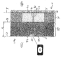
- the figure shows the outer wall 50 of a structure to be insulated, in particular a building, with an attached thermal insulation composite system 1 in a schematic cross-sectional view.
- the thermal insulation composite system 1 has numerous Insulating on each of two substantially flat and approximately parallel to each other major surfaces A, B are limited and which are attached to the outer wall 50 and cover them.
- the thermal insulation composite system 1 may comprise, in addition to the insulation boards, further layers, in particular a reinforcing layer covering the outside of the insulation boards and an outer plaster layer 70 covering the reinforcing layer.
- the illustrated insulation board 12 is part of an insulation element arrangement 10 according to the invention.
- the Dämmelementan extract 10 has, in addition to the insulation board 12, which forms the insulating element, a plurality of measuring sensors 21, 22, 31, 32 which are each attached to one of the main surfaces A, B of the insulation board 12.
- the insulation board 12 shown has a total of four measuring sensors, of which two (21, 22) are attached to the outer major surface A of the insulating board and two (31, 32) are fixed to the inner major surface B of the insulating board.
- the measuring sensors are not visible from the outside, since they are covered by the outer plaster layer 70 and are located between the insulating panel 12 and the outer wall 50.
- the measuring sensors are integrated into the insulation board 12 in such a way that the insulation board 12, like the remaining insulation boards of the composite thermal insulation system, can be mounted on the outer wall 50.
- the measuring sensors 21 and 31 are set up for temperature measurement, and the measuring sensors 22 and 32 are set up for measuring the humidity. Further measuring sensors for measuring other environmental parameters such as the heat flows can be provided. Alternatively, only one measuring sensor may be attached to the outer major surface and / or the inner major surface.
- the Dämmelementan extract further measuring sensors 41 and 42 which are mounted on the inside C of the outer wall 50 and which are adapted to measure the internal temperature (41) and the indoor humidity (42).
- the insulation board 12 has a passage 14 in a direction approximately perpendicular to the main surfaces A, B extending direction through which the connecting cables 16 of the attached to the outer major surface A measuring sensors 21, 22 are guided, and the outer wall 50 has a passage 51 in the form a hole through which the connection cables of both the outer main surface A and the inner major surface B mounted measuring sensors are guided. All connection cables are brought together in a junction box 55, which can be arranged on the inside of the outer wall 50.
- the connecting cables both at the outer main surface mounted measuring sensors 21, 22 (after the passage of the passage 16) and the connecting cables of the measuring sensors mounted on the inner main surface B may have a length which is greater than a thickness X of the outer wall 50, so that the connecting cables can be guided through the implementation 51 into the interior of the room.
- this length is greater than 0.5 m. more preferably about 1 m.
- connection cables can be connected to a signal processing device, which in turn can be connected to a display device 60.
- the display device serves to display the environmental parameters measured by the measuring sensors and / or to display insulation characteristics calculated therefrom.
- the display device may have a monitor hanging in the interior of a room on a wall, a display o. The like.
Abstract
Die Erfindung betrifft eine Dämmelementanordnung, insbesondere für die Fassadendämmung, mit einem Dämmelement, das von zwei im Wesentlichen ebenen und etwa parallel zueinander verlaufenden Hauptflächen begrenzt ist, wobei die Dämmelementanordnung mindestens einen Messsensor zur Messung eines Umgebungsparameters, insbesondere einer Umgebungstemperatur, einer Luftfeuchtigkeit und/oder eines Wärmestroms aufweist, der einer der Hauptflächen des Dämmelements zugeordnet, insbesondere daran angebracht ist.The invention relates to a Dämmelementanordnung, in particular for the facade insulation, with an insulating element which is bounded by two substantially planar and approximately parallel main surfaces, wherein the Dämmelementanordnung at least one measuring sensor for measuring an environmental parameter, in particular an ambient temperature, humidity and / or a heat flow associated with one of the main surfaces of the Dämmelements, in particular attached thereto.
Description
Die Erfindung betrifft eine Dämmelementanordnung, insbesondere für die Fassadendämmung, mit einem Dämmelement, das von zwei im Wesentlichen ebenen und etwa parallel zueinander verlaufenden Hauptflächen begrenzt ist.The invention relates to a Dämmelementanordnung, in particular for the facade insulation, with an insulating element which is bounded by two substantially planar and approximately parallel main surfaces.
Eine solche Dämmelementanordnung kann Teil eines Wärmedämmverbundsystems sein, das regelmäßig zum Zweck der Fassadendämmung insbes im Bereich der Gebäudesanierung eingesetzt wird. Wärmedämmverbundsysteme weisen Dämmelemente aus einem wärmedämmenden Material wie etwa Polystyrolhartschaum, Mineralwolle wie etwa Stein- und Glaswolle, Mineralschaum, Kalziumsilikathydrate oder Polyurethanschaum auf, welche mit Hilfe von mechanischen Befestigungsmitteln wie etwa Dübeln oder geeigneten Klebstoffen auf einem bestehenden Untergrund einer zu dämmenden Struktur befestigt werden. Auf die Dämmplatten wird eine Armierungsschicht aus einem Armierungsgewebe und einem Armierungsmörtel aufgebracht, der gleichzeitig als Unterputz benutzt werden kann. Den Abschluss des Wärmedämmverbundsystems bildet der auf die Armierungsschicht aufgebrachte Außenputz, welcher in Abhängigkeit von den gestalterischen Anforderungen auch noch mit einer geeigneten Fassadenfarbe angestrichen werden kann.Such a Dämmelementanordnung can be part of a thermal insulation composite system, which is used regularly for the purpose of facade insulation esp. In the field of building renovation. Thermal insulation composite systems have insulating elements made of a thermally insulating material such as polystyrene foam, mineral wool such as stone and glass wool, mineral foam, calcium silicate or polyurethane foam, which are fastened by means of mechanical fasteners such as dowels or suitable adhesives on an existing surface of a structure to be insulated. On the insulation boards, a reinforcing layer of a reinforcing fabric and a reinforcing mortar is applied, which can be used simultaneously as a flush. The completion of the thermal insulation composite system is applied to the reinforcing layer applied external plaster, which can also be painted with a suitable facade color depending on the design requirements.
Bekannte Dämmelemente sind in der Druckschrift
Durch Dämmmaßnahmen wie etwa die Anbringung eines Wärmedämmverbundsystems an einer zu dämmenden Struktur wie etwa an der Außenwand eines Gebäudes wird die Energieeffizienz beim Heizen des Gebäudes verbessert bzw. die Transmissionswärmeverluste des Gebäudes werden gesenkt.Insulation measures, such as the attachment of a composite thermal insulation system to a structure to be insulated, such as on the outside wall of a building, improve the energy efficiency of heating the building or reduce the transmission heat losses of the building.
Der Energiebedarf für das Heizen eines Gebäudes sowie die Einsparung nach einer Sanierungsmaßnahme lassen sich normativ exakt berechnen. Für diese Berechnung werden die Wärmedurchgangskoeffizienten der Struktur vor der Sanierung Ualt und nach der Sanierung Uneu, die Dämmfläche A sowie die zu erwartende Temperaturdifferenz (Innen-/Außentemperatur) herangezogen. Die Wärmedurchgangskoeffizienten lassen sich u. a. aus der Wärmeleitfähigkeit sowie der Dicke der zu dämmenden Struktur und des Dämmelements bestimmen. Die tatsächliche Energieeinsparung weicht oftmals von diesem berechneten Wert ab, da dieser durch das Nutzerverhalten maßgeblich beeinflusst wird. Insbesondere haben das Lüftungs- und das Heizverhalten des Nutzers großen Einfluss auf die sich durch die Sanierung ergebende Energieeinsparung. Dies führt zu Verunsicherungen und ist vergleichbar mit den Verbrauchsangaben bei Autos, bei denen die tatsächlichen Verbrauchswerte aufgrund des Nutzerverhaltens ebenfalls von den berechneten Verbrauchswerten abweichen. Ferner herrscht oftmals Unsicherheit darüber, ob mit einer Sanierungsmaßnahme die Gefahr für Schimmelpilzbildung verbunden ist, bzw. ob ein gutes Innenraumklima erhältlich ist.The energy requirement for heating a building as well as the savings after a refurbishment measure can be accurately calculated normatively. For this calculation, the heat transfer coefficients of the structure before the renovation U old and after the renovation U new , the insulation area A and the expected temperature difference (indoor / outdoor temperature) are used. The heat transfer coefficients can be determined inter alia from the thermal conductivity as well as the thickness of the structure to be insulated and the Dämmelements. The actual energy saving often deviates from this calculated value, since this is significantly influenced by the user behavior. In particular, the ventilation and heating behavior of the user have a major influence on the energy savings resulting from the renovation. This leads to uncertainty and is comparable to the consumption data for cars, where the actual consumption values also differ from the calculated consumption values due to the user behavior. Furthermore, there is often uncertainty as to whether a remediation measure is associated with the danger of mold fungus formation or whether a good indoor climate is available.
Die Steigerung der Energieeffizienz im Gebäudesektor wird nicht zuletzt deshalb derzeit kontrovers diskutiert, weil es oftmals an der Vorstellung mangelt, welche Sanierungsmaßnahmen zu welchen tatsächlichen Ergebnissen führen. Ferner werden die Nutzer teilweise nach der Durchführung einer Sanierungsmaßnahme nicht in ausreichendem Maß über ein im Hinblick auf Energieeffizienz und geringe Schimmelbildung optimales Heiz- und Lüftungsverhalten aufgeklärt, bzw. entsprechende Aufklärungsmaßnahmen geraten beim Nutzer in Vergessenheit, so dass aufgrund eines falschen Heiz- und Lüftungsverhaltens letztlich nicht die theoretisch möglichen Werte für Energieeinsparung und optimales Raumklima erhalten werden.The increase in energy efficiency in the building sector is currently being discussed controversially, because there is often a lack of ideas as to which renovation measures will lead to which actual results. Furthermore, some users are not adequately informed about the optimum heating and ventilation behavior with regard to energy efficiency and low mold formation, or the corresponding information campaigns are forgotten by the user, so due to incorrect heating and ventilation behavior not the theoretically possible values for energy saving and optimal indoor climate are obtained.
In Anbetracht dieser Probleme ist es die Aufgabe der vorliegenden Erfindung, die durch eine Dämmmaßnahme zu erhaltende Energieeinsparung und die sich ergebenden Raumklimawerte zu verbessern.In view of these problems, it is the object of the present invention to improve the energy saving to be obtained by an insulation measure and the resulting indoor climate values.
Diese Aufgabe wird erfindungsgemäß durch eine Weiterbildung der beschriebenen Dämmelementanordnung gelöst, die im Wesentlichen dadurch gekennzeichnet ist, dass die Dämmelementanordnung mindestens einen Messsensor zur Messung eines Umgebungsparameters, insbesondere einer Umgebungstemperatur, einer Luftfeuchtigkeit und/oder eines Wärmestroms aufweist, der einer der Hauptflächen des Dämmelements zugeordnet, insbesondere daran angebracht ist.This object is achieved by a development of the described Dämmelementanordnung, which is characterized essentially in that the Dämmelementanordnung comprises at least one measuring sensor for measuring an environmental parameter, in particular an ambient temperature, humidity and / or heat flow associated with one of the main surfaces of the Dämmelements , in particular attached thereto.
Die Erfindung geht auf die Erkenntnis zurück, dass eine transparente Darstellung der Auswirkungen von Sanierungsmaßnahmen erforderlich ist, um die Akzeptanz solcher Maßnahmen zu erhöhen und den Nutzer dazu zu veranlassen, sein Verhalten so anzupassen, dass optimale Energieeinsparwerte erhalten werden. Diese Transparenz wird erfindungsgemäß dadurch erreicht, dass das Dämmelement auf einer seiner Begrenzungsflächen, nämlich entweder auf der inneren Hauptfläche, die der zu dämmenden Struktur zugewandt ist, oder auf der äußeren Hauptfläche, die dem Außenraum zugewandt ist, mit einem Messsensor zur Messung eines Umgebungsparameters ausgestattet ist. Der gemessene Umgebungsparameter lässt Rückschlüsse auf die tatsächlichen Auswirkungen der Sanierungsmaßnahme zu. Der Nutzer kann den Wert des Umgebungsparameters übersehen und überwachen, und sein Heizverhalten entsprechend anpassen.The invention is based on the recognition that a transparent presentation of the effects of remedial measures is required in order to increase the acceptance of such measures and to induce the user to adapt his behavior in such a way that optimum energy-saving values are obtained. This transparency is inventively achieved in that the insulating element on one of its boundary surfaces, namely either on the inner main surface, which faces the structure to be insulated, or on the outer main surface, which faces the outer space, equipped with a measuring sensor for measuring an environmental parameter is. The measured environmental parameter allows conclusions about the actual effects of the remedial measure. The user can oversee and monitor the value of the environmental parameter and adjust their heating behavior accordingly.
"Angebracht" bedeutet erfindungsgemäß, dass der Messsensor derart an einer der Hauptflächen des Dämmelements befestigt ist bzw. in die Hauptfläche derart integriert ist, dass der Wert des Umgebungsparameters auf der entsprechenden Seite des Dämmelements gemessen werden kann.According to the invention, "attached" means that the measuring sensor is fastened to one of the main surfaces of the insulating element or integrated into the main surface in such a way that the value of the environmental parameter can be measured on the corresponding side of the insulating element.
Da der Messsensor an einer der Hauptflächen des Dämmelements angebracht ist, ist er nach dem Installieren des Wärmedämmverbundsystems an der zu dämmenden Struktur nicht mehr von außen sichtbar: Die innere Hauptfläche des Dämmelement ist der zu dämmenden Struktur zugewandt und die äußere Hauptfläche des Dämmelements ist von einer Deckschicht wie etwa von einer Armierungs- oder Putzschicht bedeckt, die regelmäßig keine ins Gewicht fallende Dämmungseigenschaft hat. Dies führt zum einen zu einer optisch ansprechenden gedämmten Struktur und verhindert zum anderen Beschädigungen des Messsensors durch mechanische Einwirkungen, übermäßige Sonneneinstrahlung oder andere Witterungseinflüsse.Since the measuring sensor is attached to one of the main surfaces of the Dämmelements, he is no longer visible from the outside after installing the thermal insulation composite system on the structure to be insulated: The inner main surface of the Dämmelement faces the structure to be insulated and the outer main surface of the Dämmelements is of a Covering layer such as covered by a reinforcing or plaster layer, which regularly has no significant insulation property. On the one hand, this leads to a visually appealing, insulated structure and, on the other hand, prevents damage to the measuring sensor due to mechanical effects, excessive solar radiation or other weather influences.
Bspw. lassen sich durch einen an der inneren Hauptfläche angebrachten Luftfeuchtigkeitssensor Rückschlüsse auf die Gefahr einer Schimmelpilzbildung ziehen. Bspw. lassen sich durch einen an der inneren Hauptfläche angebrachten Temperatursensor Rückschlüsse auf die Dämmwirkung des Dämmelements gegenüber der Dämmwirkung der zu dämmenden Struktur ohne Dämmelement ziehen. Bspw. lässt sich durch einen an der äußeren Hauptfläche angebrachten Temperatursensor die Außentemperatur dauerhaft überwachen, ohne dass an der Außenwand ein Temperaturmesser sichtbar ist, der ferner anfällig für Beschädigungen ist. Alternativ lässt sich der zwischen den beiden Hauptflächen des Dämmelements fließende Wärmestrom mit einem entsprechenden Messsensor auch direkt messen, so dass unmittelbar Rückschlüsse über Transmissionswärmeverluste nach/vor der Dämmmaßnahme gezogen werden können. An der äußeren und/oder an der inneren Hauptfläche können erfindungsgemäß jeweils mehrere Messsensoren zur Messung verschiedener Umgebungsparameter angebracht sein.For example. With the help of an air humidity sensor attached to the inner main surface, it is possible to draw conclusions about the danger of mold fungus formation. For example. can be drawn by a mounted on the inner surface temperature sensor conclusions on the insulating effect of Dämmements against the insulating effect of the structure to be insulated without insulating element. For example. With a temperature sensor attached to the outer main surface, it is possible to permanently monitor the outside temperature without the presence of a temperature gauge on the outside wall which is also prone to damage. Alternatively, the heat flow flowing between the two main surfaces of the insulating element can also be measured directly with a corresponding measuring sensor, so that conclusions about transmission heat losses can be drawn immediately after / before the insulation measure. According to the invention, a plurality of measuring sensors for measuring different environmental parameters can be attached to the outer and / or the inner main surface in each case.
Zweckmäßigerweise weist die erfindungsgemäße Dämmelementanordnung einen zweiten Messsensor zur Messung eines Umgebungsparameters auf, der an der der ersten Hauptfläche entgegengesetzten Hauptfläche des Dämmelements angebracht ist. Mit anderen Worten ist der erste Messsensor an der nach außen gewandten Hauptfläche des Dämmelements und der zweite Messsensor an der nach innen in Richtung auf die zu dämmende Struktur gewandten Hauptfläche des Dämmelements vorzugsweise auf etwa gleicher Höhe und Breite wie der erste Messsensor angebracht. Besonders bevorzugt sind beide Messsensoren jeweils in einem zentralen Bereich der Dämmplatte angebracht. Es hat sich als sinnvoll herausgestellt, dass der erste und der zweite Sensor zur Messung desselben Umgebungsparameters eingerichtet sind. Wenn bspw. beide Messsensoren zur Messung der Temperatur eingerichtet sind, kann unter Rückgriff auf einen zuvor bestimmten Wert des Wärmedurchgangskoeffizienten des Dämmelements der Wärmestrom durch das Dämmelement berechnet werden. Alternativ oder zusätzlich kann der Wärmefluss durch entsprechende, an der inneren und der äußeren Hauptfläche angebrachte Messsensoren direkt gemessen werden.The insulation element arrangement according to the invention expediently has a second measuring sensor for measuring an environmental parameter which is attached to the main surface of the insulating element opposite the first main surface. In other words, the first measuring sensor is attached to the outwardly facing main surface of the Dämmelements and the second measuring sensor on the inwardly towards the structure to be insulated facing main surface of the Dämmelements preferably at about the same height and width as the first measuring sensor. Particularly preferably, both measuring sensors are each mounted in a central region of the insulating board. It has proven to be expedient that the first and the second sensor are set up to measure the same environmental parameter. If, for example, both measuring sensors are set up to measure the temperature, the heat flow through the insulating element can be calculated by recourse to a previously determined value of the heat transfer coefficient of the insulating element. Alternatively or additionally, the heat flow can be measured directly by means of corresponding measuring sensors attached to the inner and outer main surfaces.
Im Hinblick auf eine einfache Installation der Dämmelementanordnung an der zu dämmenden Struktur hat es sich als zweckmäßig herausgestellt, wenn der erste Messsensor in die erste Hauptfläche des Dämmelements integriert ist und/oder der zweite Messsensor in die zweite Hauptfläche integriert ist. Insbesondere steht der Messsensor ausgehend von der etwa ebenen Hauptfläche des Dämmelements weniger als 1 cm, bevorzugt weniger als 0,5 cm, besonders bevorzugt überhaupt nicht vor. Der Messsensor kann also zumindest teilweise in eine Vertiefung in der Hauptfläche des Dämmelements eingelassen sein und/oder kann als in Dickenrichtung der Dämmplatte dünnes Element ausgeführt sein. Der Messsensor kann an der Dämmplatte angeklebt oder mit Befestigungselementen befestigt sein.With regard to a simple installation of the Dämmelementanordnung on the structure to be insulated, it has been found to be useful if the first measuring sensor is integrated into the first main surface of the Dämmelements and / or the second measuring sensor is integrated into the second main surface. In particular, starting from the approximately flat main surface of the insulating element, the measuring sensor is less than 1 cm, preferably less than 0.5 cm, particularly preferably not at all. The measuring sensor can therefore at least may be partially embedded in a recess in the main surface of the Dämmelements and / or may be designed as in the thickness direction of the insulation board thin element. The measuring sensor can be glued to the insulating board or fastened with fastening elements.
Eine bevorzugte Ausführungsform der erfindungsgemäßen Dämmelementanordnung zeichnet sich durch mindestens einen weiteren Messsensor zur Messung eines Umgebungsparameters im Inneren der mit dem Dämmelement zu dämmenden Struktur aus. Der weitere Messsensor kann unter einem Abstand von der inneren Hauptfläche des Dämmelements angeordnet sein, wobei dieser Abstand etwa der Dicke der zu dämmenden Struktur, insbesondere einer Außenwand entsprechen kann. Auf diese Weise sind insgesamt drei Messebenen gebildet: eine äußere Messebene auf der Außenseite, die etwa durch die äußere Hauptfläche des Dämmelements parallel zu dieser verläuft, eine Zwischen-Messebene, die etwa durch die innere Hauptfläche des Dämmelements parallel zu dieser verläuft, und eine innere Messebene, die parallel zu den anderen Messebenen durch den Innenraum der zu dämmenden Struktur verläuft. Die Werte der Umgebungsparameter in diesen drei Messebenen lassen Rückschlüsse über die Energieeinsparung infolge der Sanierungsmaßnahme, über die Gefahr einer Schimmelpilzbildung, sowie über Wärmeströme durch Außenwand und Dämmelement zu, so dass der Nutzer einen Überblick über die Auswirkungen der Dämmmaßnahme erhält, wenn er die Messwerte regelmäßig abliest und sein Heiz- und Lüftverhalten entsprechend anpasst.A preferred embodiment of the insulating element arrangement according to the invention is characterized by at least one further measuring sensor for measuring an environmental parameter in the interior of the structure to be insulated with the insulating element. The further measuring sensor may be arranged at a distance from the inner main surface of the insulating element, wherein this distance may correspond approximately to the thickness of the structure to be insulated, in particular an outer wall. In this way, a total of three measurement levels are formed: an outer measurement plane on the outside, which runs approximately through the outer main surface of the Dämmelements parallel to this, an intermediate measuring plane, which runs parallel to this through the inner main surface of the Dämmelements, and an inner Measuring level, which runs parallel to the other measurement levels through the interior of the structure to be insulated. The values of the environmental parameters in these three measurement levels allow conclusions about the energy savings as a result of the remedial measures, about the risk of mold formation, as well as heat flows through the outer wall and the insulation element, so that the user gets an overview of the effects of the insulation measure if he regularly measures the measurements read and adapt its heating and ventilating behavior accordingly.
Die Energieeinspareffekte der Sanierungsmaßnahme lassen sich für die zu dämmende Struktur darstellen, wenn der erste Messsensor ein äußerer Messsensor zur Messung der Umgebungstemperatur an der äußeren Hauptfläche des Dämmelements ist, der zweite Messsensor ein innerer Messsensor zur Messung der Umgebungstemperatur an der inneren Hauptfläche des Dämmelements und/oder der dritte Messsensor ein Messsensor zur Messung einer Innenraumtemperatur ist.The energy saving effects of the remediation measure can be represented for the structure to be insulated if the first measuring sensor is an external measuring sensor for measuring the ambient temperature on the outer main surface of the insulating element, the second measuring sensor is an internal measuring sensor for measuring the ambient temperature on the inner main surface of the insulating element and / or the third measuring sensor is a measuring sensor for measuring an interior temperature.
Bspw. lässt sich der Wärmestrom aus den gemessenen Temperaturwerten mittels der folgenden Formel berechnen: ![]()

![]()
Ialt/neu ist der Wärmestrom (in Watt), Tinnen ist die Innentemperatur, Tauße, ist die Außentemperatur, Uneu ist der Wärmedurchgangskoeffizient der gedämmten Struktur, Ualt ist der Wärmedurchgangskoeffizient der Struktur vor der Dämmung und A ist die Dämmfläche. Die sich ergebenden Transmissionswärmeverluste vor und nach der Dämmmaßnahme können angezeigt und abgelesen werden. Durch Summation können auch die monatlichen, jährlichen etc. Wärmeverluste berechnet und ebenfalls angezeigt werden. Durch einen Vergleich alt/neu ergibt sich die Energieeinsparung. Alternative Berechnungsmethoden können der einschlägigen Fachliteratur entnommen werden.I old / new is the heat flow (watts), T is inside the indoor temperature, T outsid, the outside temperature, U new heat transfer coefficient of the insulated structure, U is old is the heat transfer coefficient of the structure before the insulation and A is the insulating surface. The resulting transmission heat losses before and after the insulation can be displayed and read. By summation, the monthly, annual, etc. heat losses can be calculated and also displayed. By comparing old / new results in the energy savings. Alternative calculation methods can be found in the relevant specialist literature.
Unterschiede im Temperaturabfall zwischen der äußeren Messebene und der Zwischen-Messebene sowie zwischen der Zwischen-Messebene und der inneren Messebene lassen Rückschlüsse auf die Wirkung der Dämmmaßnahme zu. Die einzelnen Temperaturen können gespeichert, überwacht und/oder dem Nutzer separat angezeigt werden. Die Gebäudeheizung kann entsprechend gesteuert und/oder geregelt werden.Differences in the temperature drop between the outer measurement level and the intermediate measurement level and between the intermediate measurement level and the inner measurement level allow conclusions to be drawn about the effect of the insulation measure. The individual temperatures can be stored, monitored and / or displayed to the user separately. The building heating can be controlled and / or regulated accordingly.
Falls die tatsächliche Energieeinsparung nicht der zu erwartenden Energieeinsparung entspricht, kann der Nutzer ferner darüber informiert werden, dass er sein Heiz- und/oder Lüftverhalten ändern sollte.If the actual energy saving does not correspond to the expected energy savings, the user can also be informed that he should change his heating and / or ventilation behavior.
Alternativ kann der erste Messsensor ein äußerer Messsensor zur Messung der Luftfeuchtigkeit an der äußeren Hauptfläche des Dämmelements, der zweite Messsensor ein innerer Messsensor zur Messung der Luftfeuchtigkeit an der inneren Hauptfläche des Dämmelements und/oder der dritte Messsensor ein Messsensor zur Messung einer Innenraumluftfeuchtigkeit sein. Durch Messung der Luftfeuchtigkeitswerte können Rückschlüsse auf das Raumklima sowie die Gefahr einer Schimmelpilzbildung gezogen werden. Falls die Gefahr einer Schimmelpilzbildung besteht, kann der Nutzer darüber informiert werden, dass er sein Heiz- und/oder Lüftverhalten ändern sollte.Alternatively, the first measuring sensor may be an external measuring sensor for measuring the humidity at the outer main surface of the insulating element, the second measuring sensor may be an inner measuring sensor for measuring the humidity at the inner main surface of the insulating element and / or the third measuring sensor may be a measuring sensor for measuring an indoor air humidity. By measuring the humidity values it is possible to draw conclusions about the indoor climate as well as the risk of mold fungus formation. If there is a risk of mold fungus formation, the user can be informed that he should change his heating and / or ventilation behavior.
Wenn sowohl Temperatur als auch relative Luftfeuchtigkeit in einer Messebene gemessen werden, lässt sich daraus mittels der üblichen Berechnungsmethoden die Gefahr der Schimmelpilzbildung in dieser Messebene aufzeigen, bzw. umgekehrt lässt sich die Sicherheit vor Schimmelpilzbildung demonstrieren. Die Gefahr für Schimmelpilzbildung kann in den verschiedenen Messebenen unterschiedlich hoch sein, so dass eine Messung sowohl an der inneren Hauptfläche als auch an der äußeren Hauptfläche des Dämmelements sinnvoll sein kann.If both temperature and relative humidity are measured in one measuring level, the usual calculation methods can be used to demonstrate the danger of mold formation at this measuring level, or vice versa, the safety against mold formation can be demonstrated. The risk of mold growth in the different measurement levels can vary, so that a measurement on both the inner main surface and on the outer main surface of the Dämmelements can be useful.
In einer besonders bevorzugten Ausführungsform weist die Dämmelementanordnung mindestens zwei an jeder Hauptfläche des Dämmelements angebrachte Messsensoren zur Messung verschiedener Umgebungsparameter auf. Zusätzlich kann die Dämmelementanordnung mindestens zwei Messsensoren auf der Innenseite der zu dämmenden Struktur aufweisen. Bspw. sind sowohl an der äußeren als auch an der inneren Hauptfläche des Dämmelements jeweils ein Temperaturmessgerät und ein Luftfeuchtigkeitsmessgerät angebracht.In a particularly preferred embodiment, the insulating element arrangement has at least two measuring sensors attached to each main surface of the insulating element for measuring various environmental parameters. In addition, the Dämmelementanordnung have at least two measuring sensors on the inside of the structure to be insulated. For example. Both on the outer and on the inner main surface of the Dämmelements are each mounted a temperature measuring device and a humidity meter.
Die Dämmelementanordnung kann eine durch das Dämmelement hindurchführende Durchführung zum Durchführen von Anschlussleitungen mindestens eines Messsensors durch das Dämmelement in einer quer, insbesondere etwa senkrecht zu den Hauptflächen verlaufenden Richtung aufweisen. Diese Durchführung dient zur Verlegung der Anschlussleitungen der an der äußeren Hauptfläche des Dämmelements angebrachten Messsensoren in Richtung auf die innere Hauptfläche oder umgekehrt. Das Anbringen der Messsensoren an der äußeren Hauptfläche wird so vereinfacht, da deren Anschlussleitungen durch die Durchführung geführt und ausgehend von der Innenseite des Dämmelements ggf. zusammen mit den Anschlussleitungen von Messsensoren an der inneren Hauptfläche mit einer Stromversorgungseinrichtung und/oder einer Verarbeitungseinrichtung verbunden werden können. Dazu sind die Anschlussleitungen mindestens eines an der äußeren Hauptfläche angebrachten Messsensors durch die Durchführung geführt, so dass sie an der inneren Hauptfläche aus dem Dämmelement heraustreten. Das Installieren der Dämmelementanordnung an der zu dämmenden Struktur wird auf diese Weise vereinfacht, da einer Verkabelung nur auf der inneren Seite der Dämmelementanordnung erforderlich ist.The insulating element arrangement can have a passage leading through the insulating element for passing connecting lines of at least one measuring sensor through the insulating element in a direction running transversely, in particular approximately perpendicular to the main surfaces. This bushing is used to lay the connection lines of the measuring sensors attached to the outer main surface of the insulating element in the direction of the inner main surface or vice versa. The mounting of the measuring sensors on the outer main surface is simplified in such a way that their connecting leads can be guided through the leadthrough and, starting from the inside of the insulating element, possibly together with the connecting leads of measuring sensors on the inner main surface to a power supply device and / or a processing device. For this purpose, the connection lines of at least one measuring sensor attached to the outer main surface are guided through the leadthrough, so that they emerge from the insulating element on the inner main surface. Installing the Dämmelementanordnung on the structure to be insulated is simplified in this way, since a wiring is required only on the inner side of the Dämmelementanordnung.
Zweckmäßigerweise ist eine Länge der Anschlussleitungen der Messsensoren ausgehend von der inneren Hauptfläche des Dämmelements länger als 30 cm, insbesondere länger als 50 cm. Insbesondere beträgt die Länge etwa 1 m oder mehr. Die Anschlussleitungen können so durch einen Durchgang durch die zu dämmende Struktur geführt werden und im Innenraum der Struktur ggf. zusammen mit Anschlussleitungen dort angeordneter weiterer Messsensoren mit weiteren Einrichtungen verbunden werden.Expediently, a length of the connecting lines of the measuring sensors starting from the inner main surface of the insulating element is longer than 30 cm, in particular longer than 50 cm. In particular, the length is about 1 m or more. The connecting lines can thus be guided through a passage through the structure to be insulated and, if appropriate, together with connecting lines arranged there, further measuring sensors can be connected to other devices in the interior of the structure.
Im Hinblick auf die Nutzerfreundlichkeit hat es sich als zweckmäßig erwiesen, dass die Dämmelementanordnung eine mit den Messsensoren gekoppelte Signalverarbeitungseinrichtung aufweist, die zur Berechnung einer Kenngröße, insbes. einer Dämmungskenngröße aus einem oder mehreren der gemessenen Umgebungsparameter eingerichtet ist. Die Signalverarbeitungseinrichtung kann einen Speicher aufweisen, in der bspw. Wärmedurchgangskoeffizienten der einzelnen Bauteile abgespeichert sind, mit denen unter Verwendung der gemessenen Umgebungsparameter Dämmungskenngrößen wie etwa Wärmeströme, Transmissionswärmeverluste, Energieeinsparung, Energieeffizienz etc. von der Signalverarbeitungseinrichtung berechnet werden.With regard to the user-friendliness, it has proved expedient that the insulating element arrangement has a signal processing device coupled to the measuring sensors, which is set up for calculating a parameter, in particular an insulation parameter from one or more of the measured environmental parameters. The signal processing device may have a memory in which, for example, heat transfer coefficients of the individual components are stored, with which by using the measured environmental parameters Dämmungskungrößen such Heat flows, transmission heat losses, energy savings, energy efficiency, etc. are calculated by the signal processing device.
Die berechneten Dämmungskenngrößen und/oder die Messwerte der Messsensoren können durch eine Anzeigevorrichtung angezeigt werden. Die Anzeigevorrichtung kann bspw. ein Display oder ein Monitor sein. Die Signalverarbeitungseinrichtung kann derart programmiert sein, dass die Temperatur und/oder Luftfeuchtigkeit in verschiedenen Messebenen in vorbestimmten oder vom Nutzer einstellbaren Zeitintervallen gemessen wird und in Form eines Diagramms von der Anzeigevorrichtung angezeigt wird. Aus den gemessenen Temperaturwerten kann die Signalverarbeitungseinrichtung bspw. jeweils unter Rückgriff auf im Speicher abgespeicherte Werte den aktuellen Wärmestrom durch die Dämmfläche berechnen, der wiederum von der Anzeigevorrichtung angezeigt werden kann. Die gesamte durch die Dämmfläche tretende Wärmeenergie kann berechnet werden und mit derjenigen Wärmeenergie verglichen werden, die ohne die Dämmmaßnahme bei gleichen Temperaturen durch die Dämmfläche treten würde. Die seit Durchführung der Sanierungsmaßnahme eingesparte Gesamtenergie kann in summierter Form angezeigt werden. Die Berechnung weiterer Dämmkenngrößen aus denselben und/oder weiteren Messwerten ist gleichermaßen möglich, wobei die Messwerte und die berechneten Dämmkenngrößen vorzugsweise in für den Nutzer aufbereiteter Form von der Anzeigeeinrichtung angezeigt werden.The calculated insulation characteristics and / or the measured values of the measuring sensors can be displayed by a display device. The display device may be, for example, a display or a monitor. The signal processing device can be programmed in such a way that the temperature and / or air humidity in different measurement planes is measured at predetermined or user-settable time intervals and is displayed in the form of a diagram by the display device. From the measured temperature values, the signal processing device can, for example, in each case calculate the current heat flow through the insulating surface, which in turn can be displayed by the display device, by recourse to values stored in the memory. The entire heat energy passing through the insulating surface can be calculated and compared with the thermal energy that would pass through the insulating surface without the insulation measure at the same temperatures. The total energy saved since implementation of the rehabilitation measure can be displayed in summed form. The calculation of further insulation parameters from the same and / or further measured values is likewise possible, with the measured values and the calculated insulation parameters preferably being displayed by the display device in a form prepared for the user.
Das Dämmelement kann eine Dämmplatte eines Wärmedämmverbundsystems sein. Die Auswirkungen der Installation eines Wärmedämmverbundsystems im Hinblick auf Energieverbrauch und Raumklima sind für den Nutzer von besonderem Interesse. Im Übrigen hat das Heiz- und Lüftverhalten des Nutzers in diesem Fall einen besonderen Einfluss auf die Auswirkung der Dämmmaßnahme.The insulating element may be an insulating board of a thermal insulation composite system. The effects of installing a thermal insulation composite system with regard to energy consumption and indoor climate are of particular interest to the user. Incidentally, the heating and ventilating behavior of the user in this case has a special influence on the effect of the insulation measure.
Das Dämmelement kann aus Dämmstoffen wie etwa Mineralwolle (MW), expandiertem Polystyrol (EPS), Polyurethan (PUR/PIR), Phenolharz (PF) und/oder Holzfaser bestehen. In einer besonders bevorzugten Ausführungsform besteht das Dämmelement zumindest teilweise aus expandiertem Polystyrol, in das werkseitig bevorzugt je Elementseite eine oder mehrere, vorzugsweise zwei Messsensoren integriert sind. Expandiertes Polystyrol hat sich im Hinblick auf gute Dämmeigenschaften als besonders vorteilhaft herausgestellt.The insulating element may consist of insulating materials such as mineral wool (MW), expanded polystyrene (EPS), polyurethane (PUR / PIR), phenolic resin (PF) and / or wood fiber. In a particularly preferred embodiment, the insulating element consists at least partially of expanded polystyrene, in the factory preferably per element side one or more, preferably two measuring sensors are integrated. Expanded polystyrene has proven to be particularly advantageous in terms of good insulation properties.
Die Erfindung betrifft ferner ein Wärmedämmverbundsystem mit einer oder mit mehreren darin eingebauten erfindungsgemäßen Dämmelementanordnungen. Im Zuge derThe invention further relates to a composite thermal insulation system with one or more incorporated therein Dämmelementanordnungen. In the course of
Montage des Wärmedämmverbundsystems wird eine oder werden wahlweise mehrere erfindungsgemäße Dämmelementanordnungen an vorgesehener Stelle, idealerweise witterungsgeschützt ohne Sonneneinwirkung wie übliche WDVS-Platten montiert.Assembly of the thermal insulation composite system is one or optionally several inventive Dämmelementanordnungen at the intended location, ideally protected from the weather without sun exposure as conventional ETICS boards mounted.
Die Erfindung betrifft weiterhin ein Verfahren zum Anbringen einer erfindungsgemäßen Dämmelementanordnung an einer zu dämmenden Struktur, insbesondere an einer Außenwand. Das Dämmelement der Dämmelementanordnung wird an einer Außenseite der Struktur angebracht, und ein Messsensor der Dämmelementanordnung wird vorzugsweise an einer der Außenseite entgegengesetzten Innenseite der Struktur angebracht. Dies ermöglicht die Messung des Umgebungsparameters zum einen im Inneren der zu dämmenden Struktur und zum anderen außerhalb der zu dämmenden Struktur an zumindest einer der Hauptflächen des Dämmelements, so dass die Auswirkungen der Dämmung überwacht und dargestellt werden können.The invention further relates to a method for attaching a Dämmelementanordnung invention to a structure to be insulated, in particular on an outer wall. The insulating element of the Dämmelementanordnung is attached to an outer side of the structure, and a measuring sensor of the Dämmelementanordnung is preferably attached to an outer side of the inside of the structure opposite to the outside. This allows the measurement of the environmental parameter on the one hand in the interior of the structure to be insulated and on the other hand outside of the structure to be insulated on at least one of the main surfaces of the Dämmelements so that the effects of the insulation can be monitored and displayed.
Vor dem Anbringen der Dämmplatte kann ein durch die Struktur führender Durchgang zur Durchführung von Anschlussleitungen der an der Dämmplatte angebrachten Messsensoren gebildet werden. Dies kann dadurch geschehen, dass vor dem Montieren der Dämmplatte an der Außenwand etwa mittig der Dämmplatte ein Loch durch die Außenwand gebohrt wird, um die Anschlussleitungen der Messsensoren in das Gebäudeinnere zu führen. Die Anschlussleitungen der Messsensoren können in einer an der Innenseite der Struktur gebildeten Verbindungsdose zusammengeführt werden. Eine Signalverarbeitungseinrichtung und/oder eine Anzeigeeinrichtung zum Anzeigen der Messwerte und/oder der aus den Messwerten berechteten Dämmungskenngrößen kann mit den in der Verbindungsdose zusammengeführten Anschlussleitungen verbunden werden. Die Anzeigeeinrichtung kann bspw. im Rauminneren in der Umgebung der Verbindungsdose angebracht werden.Before attaching the insulation board, a passage leading through the structure can be formed for the passage of connecting lines of the measuring sensors attached to the insulation board. This can be done by drilling a hole through the outer wall about the center of the insulation board before mounting the insulation board on the outer wall in order to guide the leads of the measuring sensors in the building interior. The connecting leads of the measuring sensors can be brought together in a junction box formed on the inside of the structure. A signal processing device and / or a display device for displaying the measured values and / or the insulation characteristics that are justified from the measured values can be connected to the connecting lines that are combined in the junction box. The display device can be mounted, for example, in the interior of the room in the vicinity of the junction box.
In der folgenden Beschreibung wird die Erfindung unter Bezugnahme auf die Zeichnung beispielhaft erläutert. Die einzige Figur der Zeichnung zeigt
eine schematische Querschnittdarstellung einer erfindungsgemäßen Dämmelementanordnung, die an einer zu dämmenden Struktur angebracht ist.In the following description, the invention will be described by way of example with reference to the drawings. The only figure of the drawing shows
a schematic cross-sectional view of a Dämmelementanordnung invention, which is attached to a structure to be insulated.
Die Figur zeigt die Außenwand 50 einer zu dämmenden Struktur, insbesondere eines Gebäudes, mit einem daran angebrachten Wärmedämmverbundsystem 1 in einer schematischen Querschnittdarstellung. Das Wärmedämmverbundsystem 1 weist zahlreiche Dämmplatten auf, die jeweils von zwei im Wesentlichen ebenen und etwa parallel zueinander verlaufenden Hauptflächen A, B begrenzt sind und die an der Außenwand 50 befestigt sind und diese bedecken. Das Wärmedämmverbundsystem 1 kann neben den Dämmplatten weitere Schichten aufweisen, insbesondere eine die Außenseite der Dämmplatten bedeckende Armierungsschicht und eine die Armierungsschicht bedeckende Außenputzschicht 70. Die dargestellte Dämmplatte 12 ist Teil einer erfindungsgemäßen Dämmelementanordnung 10.The figure shows the
Die Dämmelementanordnung 10 weist neben der Dämmplatte 12, die das Dämmelement bildet, mehrere Messsensoren 21, 22, 31, 32 auf, die jeweils an einer der Hauptflächen A, B der Dämmplatte 12 angebracht sind. Die dargestellte Dämmplatte 12 weist insgesamt vier Messsensoren auf, von denen zwei (21, 22) an der äußeren Hauptfläche A der Dämmplatte befestigt sind und zwei (31, 32) an der inneren Hauptfläche B der Dämmplatte befestigt sind. Die Messsensoren sind von außen nicht sichtbar, da sie von der Oberputzschicht 70 abgedeckt sind bzw. sich zwischen Dämmplatte 12 und Außenwand 50 befinden. Vorzugsweise sind die Messsensoren derart in die Dämmplatte 12 integriert, dass die Dämmplatte 12 wie die übrigen Dämmplatten des Wärmedämmverbundsystems an der Außenwand 50 montiert werden kann.The
Die Messsensoren 21 und 31 sind zur Temperaturmessung eingerichtet und die Messsensoren 22 und 32 sind zur Luftfeuchtigkeitsmessung eingerichtet. Weitere Messsensoren zur Messung weiterer Umgebungsparameter wie etwa der Wärmeströme können vorgesehen sein. Alternativ kann nur ein Messsensor an der äußeren Hauptfläche und/oder der inneren Hauptfläche angebracht sein.The measuring
Zusätzlich weist die Dämmelementanordnung weitere Messsensoren 41 und 42 auf, die an der Innenseite C der Außenwand 50 angebracht sind und die zur Messung der Innentemperatur (41) und der Innenraum-Luftfeuchtigkeit (42) eingerichtet sind.In addition, the Dämmelementanordnung further measuring
Die Dämmplatte 12 weist einen Durchgang 14 in einer etwa senkrecht zu den Hauptflächen A, B verlaufenden Richtung auf, durch den die Anschlusskabel 16 der an der äußeren Hauptfläche A angebrachten Messsensoren 21, 22 geführt sind, und die Außenwand 50 weist einen Durchgang 51 in Form eines Lochs auf, durch den die Anschlusskabel sowohl der an der äußeren Hauptfläche A als auch der an der inneren Hauptfläche B angebrachten Messsensoren geführt sind. Alle Anschlusskabel sind in einer Verbindungsdose 55 zusammengeführt, die an der Innenseite der Außenwand 50 angeordnet sein kann. Die Anschlusskabel sowohl der an der äußeren Hauptfläche angebrachten Messsensoren 21, 22 (nach dem Durchtreten der Durchführung 16) als auch die Anschlusskabel der an der inneren Hauptfläche angebrachten Messsensoren können ausgehend von der inneren Hauptfläche B eine Länge haben, die größer ist als eine Dicke X der Außenwand 50, so dass die Anschlusskabel durch die Durchführung 51 bis in das Rauminnere geführt werden können. Vorzugsweise ist diese Länge größer als 0,5 m. besonders bevorzugt etwa 1 m.The
Die Anschlusskabel können mit einer Signalverarbeitungseinrichtung verbunden sein, die wiederum mit einer Anzeigeeinrichtung 60 verbunden sein kann. Die Anzeigeeinrichtung dient zum Anzeigen der von den Messsensoren gemessenen Umgebungsparameter und/oder zum Anzeigen von daraus berechneten Dämmungskenngrößen. Die Anzeigeeinrichtung kann einen im Rauminneren an einer Wand hängenden Monitor, ein Display o. dgl. aufweisen.The connection cables can be connected to a signal processing device, which in turn can be connected to a display device 60. The display device serves to display the environmental parameters measured by the measuring sensors and / or to display insulation characteristics calculated therefrom. The display device may have a monitor hanging in the interior of a room on a wall, a display o. The like.
Claims (15)
Applications Claiming Priority (1)
| Application Number | Priority Date | Filing Date | Title |
|---|---|---|---|
| DE202013005546U DE202013005546U1 (en) | 2013-06-19 | 2013-06-19 | Dämmelementanordnung |
Publications (2)
| Publication Number | Publication Date |
|---|---|
| EP2840371A2 true EP2840371A2 (en) | 2015-02-25 |
| EP2840371A3 EP2840371A3 (en) | 2015-06-03 |
Family
ID=48915663
Family Applications (1)
| Application Number | Title | Priority Date | Filing Date |
|---|---|---|---|
| EP14001909.2A Withdrawn EP2840371A3 (en) | 2013-06-19 | 2014-06-02 | Insulating element assembly |
Country Status (2)
| Country | Link |
|---|---|
| EP (1) | EP2840371A3 (en) |
| DE (1) | DE202013005546U1 (en) |
Families Citing this family (2)
| Publication number | Priority date | Publication date | Assignee | Title |
|---|---|---|---|---|
| DE202014001581U1 (en) | 2014-02-20 | 2014-04-03 | Bachl Dämmtechnik GmbH & Co. KG | Measuring sensor carrier, measuring sensor carrier arrangement and measuring arrangement |
| DE102019000605B3 (en) * | 2019-01-30 | 2020-03-12 | Ewald Dörken Ag | Use of a sensor system arrangement in the construction sector and / or construction industry |
Citations (1)
| Publication number | Priority date | Publication date | Assignee | Title |
|---|---|---|---|---|
| WO2012022393A2 (en) | 2010-08-18 | 2012-02-23 | Schwenk Dämmtechnik Gmbh & Co. Kg | Insulating element |
Family Cites Families (3)
| Publication number | Priority date | Publication date | Assignee | Title |
|---|---|---|---|---|
| YU42759B (en) * | 1982-03-18 | 1988-12-31 | Ljubljana Avtomontaza | Heat power gauge |
| JPH0786437B2 (en) * | 1992-05-15 | 1995-09-20 | 川惣電機工業株式会社 | Method and apparatus for detecting heat flux of casting mold |
| US7831525B2 (en) * | 2008-09-08 | 2010-11-09 | International Business Machines Corporation | Automated energy transfer calculation and compensation |
-
2013
- 2013-06-19 DE DE202013005546U patent/DE202013005546U1/en not_active Expired - Lifetime
-
2014
- 2014-06-02 EP EP14001909.2A patent/EP2840371A3/en not_active Withdrawn
Patent Citations (1)
| Publication number | Priority date | Publication date | Assignee | Title |
|---|---|---|---|---|
| WO2012022393A2 (en) | 2010-08-18 | 2012-02-23 | Schwenk Dämmtechnik Gmbh & Co. Kg | Insulating element |
Also Published As
| Publication number | Publication date |
|---|---|
| EP2840371A3 (en) | 2015-06-03 |
| DE202013005546U1 (en) | 2013-06-28 |
Similar Documents
| Publication | Publication Date | Title |
|---|---|---|
| DE102006010946B3 (en) | Outside air temperature measuring apparatus with device for reducing false measurement due to strong winds | |
| AT515273B1 (en) | System for controlling the drying phase of concrete screed provided with underfloor heating | |
| EP2840371A2 (en) | Insulating element assembly | |
| DE10030294A1 (en) | Energy consumption and sanitation requirement detection method involves metrologically measuring and mathematically computing energy consumption of building, and simultaneously outputting both values | |
| DE19951105A1 (en) | Heat and / or sound insulation element | |
| DE3441733A1 (en) | Station for receiving equipment, measuring or control devices or the like | |
| DE2648272A1 (en) | Electrical instrument box for chemical plant - has corner units with mounting grooves for fixtures of insulated wall, roof and floor elements | |
| EP2149666A2 (en) | Device for the insertion of an external protection element for occasional covering or uncovering of a wall opening | |
| DE202009018102U1 (en) | Light well-Montagedämmplatte | |
| DE202014103071U1 (en) | Shutter box | |
| DE2208634C3 (en) | Device for supporting profiled roofing panels or the like | |
| EP3938715B1 (en) | Heating mat for use in a floor structure, floor structure, and method for producing same | |
| EP3147422B1 (en) | Insulating strip | |
| DE102019220431B4 (en) | Device for measuring the hygrometric humidity in building materials | |
| DE202010002768U1 (en) | Insulating element for a Untersparrendämmsystem | |
| DE102011001726A1 (en) | Module for receiving a sliding door, sliding door device and method for mounting a sliding door device | |
| DE102015118179A1 (en) | wall module | |
| EP4279683A1 (en) | Device for fixing at least one object on a roof surface | |
| DE202013105642U1 (en) | Insulating element for use in a thermal insulation composite system | |
| DE3230928A1 (en) | Device for producing an expansion joint | |
| DE102013113864A1 (en) | Insulating element for use in a thermal insulation composite system | |
| EP2634514B1 (en) | Device and method for sealing the space between the wall and floor when insulating rooms | |
| DE102017202656A1 (en) | Protective glazing apparatus and method of use thereof | |
| DE202013103283U1 (en) | groove strip | |
| CH539175A (en) | Device for keeping the assembly elements intended for fastening facade cladding at a distance from a building wall |
Legal Events
| Date | Code | Title | Description |
|---|---|---|---|
| PUAI | Public reference made under article 153(3) epc to a published international application that has entered the european phase |
Free format text: ORIGINAL CODE: 0009012 |
|
| 17P | Request for examination filed |
Effective date: 20140602 |
|
| AK | Designated contracting states |
Kind code of ref document: A2 Designated state(s): AL AT BE BG CH CY CZ DE DK EE ES FI FR GB GR HR HU IE IS IT LI LT LU LV MC MK MT NL NO PL PT RO RS SE SI SK SM TR |
|
| AX | Request for extension of the european patent |
Extension state: BA ME |
|
| PUAL | Search report despatched |
Free format text: ORIGINAL CODE: 0009013 |
|
| AK | Designated contracting states |
Kind code of ref document: A3 Designated state(s): AL AT BE BG CH CY CZ DE DK EE ES FI FR GB GR HR HU IE IS IT LI LT LU LV MC MK MT NL NO PL PT RO RS SE SI SK SM TR |
|
| AX | Request for extension of the european patent |
Extension state: BA ME |
|
| RIC1 | Information provided on ipc code assigned before grant |
Ipc: G01K 17/20 20060101AFI20150429BHEP |
|
| 17Q | First examination report despatched |
Effective date: 20170403 |
|
| RIC1 | Information provided on ipc code assigned before grant |
Ipc: G01K 17/20 20060101AFI20180724BHEP Ipc: E04B 1/76 20060101ALI20180724BHEP |
|
| STAA | Information on the status of an ep patent application or granted ep patent |
Free format text: STATUS: EXAMINATION IS IN PROGRESS |
|
| STAA | Information on the status of an ep patent application or granted ep patent |
Free format text: STATUS: THE APPLICATION IS DEEMED TO BE WITHDRAWN |
|
| 18D | Application deemed to be withdrawn |
Effective date: 20201023 |