EP2840343A2 - Abwärmerückgewinnungssystem - Google Patents
Abwärmerückgewinnungssystem Download PDFInfo
- Publication number
- EP2840343A2 EP2840343A2 EP14193505.6A EP14193505A EP2840343A2 EP 2840343 A2 EP2840343 A2 EP 2840343A2 EP 14193505 A EP14193505 A EP 14193505A EP 2840343 A2 EP2840343 A2 EP 2840343A2
- Authority
- EP
- European Patent Office
- Prior art keywords
- column
- hot water
- reboiler
- waste heat
- steam
- Prior art date
- Legal status (The legal status is an assumption and is not a legal conclusion. Google has not performed a legal analysis and makes no representation as to the accuracy of the status listed.)
- Granted
Links
Images



Classifications
-
- F—MECHANICAL ENGINEERING; LIGHTING; HEATING; WEAPONS; BLASTING
- F28—HEAT EXCHANGE IN GENERAL
- F28D—HEAT-EXCHANGE APPARATUS, NOT PROVIDED FOR IN ANOTHER SUBCLASS, IN WHICH THE HEAT-EXCHANGE MEDIA DO NOT COME INTO DIRECT CONTACT
- F28D7/00—Heat-exchange apparatus having stationary tubular conduit assemblies for both heat-exchange media, the media being in contact with different sides of a conduit wall
-
- B—PERFORMING OPERATIONS; TRANSPORTING
- B01—PHYSICAL OR CHEMICAL PROCESSES OR APPARATUS IN GENERAL
- B01D—SEPARATION
- B01D1/00—Evaporating
- B01D1/0011—Heating features
- B01D1/0058—Use of waste energy from other processes or sources, e.g. combustion gas
-
- B—PERFORMING OPERATIONS; TRANSPORTING
- B01—PHYSICAL OR CHEMICAL PROCESSES OR APPARATUS IN GENERAL
- B01D—SEPARATION
- B01D1/00—Evaporating
- B01D1/28—Evaporating with vapour compression
- B01D1/284—Special features relating to the compressed vapour
- B01D1/2856—The compressed vapour is used for heating a reboiler or a heat exchanger outside an evaporator
-
- B—PERFORMING OPERATIONS; TRANSPORTING
- B01—PHYSICAL OR CHEMICAL PROCESSES OR APPARATUS IN GENERAL
- B01D—SEPARATION
- B01D3/00—Distillation or related exchange processes in which liquids are contacted with gaseous media, e.g. stripping
- B01D3/007—Energy recuperation; Heat pumps
-
- F—MECHANICAL ENGINEERING; LIGHTING; HEATING; WEAPONS; BLASTING
- F01—MACHINES OR ENGINES IN GENERAL; ENGINE PLANTS IN GENERAL; STEAM ENGINES
- F01K—STEAM ENGINE PLANTS; STEAM ACCUMULATORS; ENGINE PLANTS NOT OTHERWISE PROVIDED FOR; ENGINES USING SPECIAL WORKING FLUIDS OR CYCLES
- F01K17/00—Using steam or condensate extracted or exhausted from steam engine plant
- F01K17/02—Using steam or condensate extracted or exhausted from steam engine plant for heating purposes, e.g. industrial, domestic
-
- F—MECHANICAL ENGINEERING; LIGHTING; HEATING; WEAPONS; BLASTING
- F01—MACHINES OR ENGINES IN GENERAL; ENGINE PLANTS IN GENERAL; STEAM ENGINES
- F01K—STEAM ENGINE PLANTS; STEAM ACCUMULATORS; ENGINE PLANTS NOT OTHERWISE PROVIDED FOR; ENGINES USING SPECIAL WORKING FLUIDS OR CYCLES
- F01K17/00—Using steam or condensate extracted or exhausted from steam engine plant
- F01K17/06—Returning energy of steam, in exchanged form, to process, e.g. use of exhaust steam for drying solid fuel or plant
-
- F—MECHANICAL ENGINEERING; LIGHTING; HEATING; WEAPONS; BLASTING
- F01—MACHINES OR ENGINES IN GENERAL; ENGINE PLANTS IN GENERAL; STEAM ENGINES
- F01K—STEAM ENGINE PLANTS; STEAM ACCUMULATORS; ENGINE PLANTS NOT OTHERWISE PROVIDED FOR; ENGINES USING SPECIAL WORKING FLUIDS OR CYCLES
- F01K23/00—Plants characterised by more than one engine delivering power external to the plant, the engines being driven by different fluids
- F01K23/02—Plants characterised by more than one engine delivering power external to the plant, the engines being driven by different fluids the engine cycles being thermally coupled
- F01K23/06—Plants characterised by more than one engine delivering power external to the plant, the engines being driven by different fluids the engine cycles being thermally coupled combustion heat from one cycle heating the fluid in another cycle
- F01K23/064—Plants characterised by more than one engine delivering power external to the plant, the engines being driven by different fluids the engine cycles being thermally coupled combustion heat from one cycle heating the fluid in another cycle in combination with an industrial process, e.g. chemical, metallurgical
-
- F—MECHANICAL ENGINEERING; LIGHTING; HEATING; WEAPONS; BLASTING
- F27—FURNACES; KILNS; OVENS; RETORTS
- F27D—DETAILS OR ACCESSORIES OF FURNACES, KILNS, OVENS OR RETORTS, IN SO FAR AS THEY ARE OF KINDS OCCURRING IN MORE THAN ONE KIND OF FURNACE
- F27D17/00—Arrangements for using waste heat; Arrangements for using, or disposing of, waste gases
- F27D17/10—Arrangements for using waste heat
- F27D17/15—Arrangements for using waste heat using boilers
-
- F—MECHANICAL ENGINEERING; LIGHTING; HEATING; WEAPONS; BLASTING
- F28—HEAT EXCHANGE IN GENERAL
- F28D—HEAT-EXCHANGE APPARATUS, NOT PROVIDED FOR IN ANOTHER SUBCLASS, IN WHICH THE HEAT-EXCHANGE MEDIA DO NOT COME INTO DIRECT CONTACT
- F28D15/00—Heat-exchange apparatus with the intermediate heat-transfer medium in closed tubes passing into or through the conduit walls ; Heat-exchange apparatus employing intermediate heat-transfer medium or bodies
-
- C—CHEMISTRY; METALLURGY
- C21—METALLURGY OF IRON
- C21C—PROCESSING OF PIG-IRON, e.g. REFINING, MANUFACTURE OF WROUGHT-IRON OR STEEL; TREATMENT IN MOLTEN STATE OF FERROUS ALLOYS
- C21C2100/00—Exhaust gas
- C21C2100/06—Energy from waste gas used in other processes
-
- F—MECHANICAL ENGINEERING; LIGHTING; HEATING; WEAPONS; BLASTING
- F28—HEAT EXCHANGE IN GENERAL
- F28D—HEAT-EXCHANGE APPARATUS, NOT PROVIDED FOR IN ANOTHER SUBCLASS, IN WHICH THE HEAT-EXCHANGE MEDIA DO NOT COME INTO DIRECT CONTACT
- F28D21/00—Heat-exchange apparatus not covered by any of the groups F28D1/00 - F28D20/00
- F28D21/0001—Recuperative heat exchangers
- F28D21/0003—Recuperative heat exchangers the heat being recuperated from exhaust gases
-
- Y—GENERAL TAGGING OF NEW TECHNOLOGICAL DEVELOPMENTS; GENERAL TAGGING OF CROSS-SECTIONAL TECHNOLOGIES SPANNING OVER SEVERAL SECTIONS OF THE IPC; TECHNICAL SUBJECTS COVERED BY FORMER USPC CROSS-REFERENCE ART COLLECTIONS [XRACs] AND DIGESTS
- Y02—TECHNOLOGIES OR APPLICATIONS FOR MITIGATION OR ADAPTATION AGAINST CLIMATE CHANGE
- Y02P—CLIMATE CHANGE MITIGATION TECHNOLOGIES IN THE PRODUCTION OR PROCESSING OF GOODS
- Y02P70/00—Climate change mitigation technologies in the production process for final industrial or consumer products
- Y02P70/10—Greenhouse gas [GHG] capture, material saving, heat recovery or other energy efficient measures, e.g. motor control, characterised by manufacturing processes, e.g. for rolling metal or metal working
Definitions
- the present invention relates to a system for recovering waste heat generated by such furnaces as distillation columns, incinerators, blast columns, and smelting columns used in various industrial fields.
- Waste heat refers to heat generated by such furnaces as distillation columns, incinerators, blast columns, and smelting columns used in various industrial fields for which no useful application is found. Waste heat produced by furnaces, boilers, dry facilities, and air conditioning facilities is often discharged in the form of combustion flue gas, whereas waste heat produced during heating, distillation, evaporation, purification, and separation processes is cooled off or condensed, and then released as cooling water. Waste heat at relatively high temperatures can be utilized for the production of low-pressure steam or for preheating boiler feed water. On the other hand, waste heat at relatively low temperatures is merely discharged to the environment due to technical difficulties as well as high equipment costs for its recovery.
- a petrochemical process may be divided into two general steps of (1) a reaction step and (2) a separationpurification step. From the perspective of energy, such a process may also be divided into (1) a heating step wherein heat is supplied, e.g., to the lower part of a column for reaction or separation/purification and (2) a cooling step wherein the upper part of a column is cooled off.
- the heating step uses steam as a heat source
- the cooling step uses cooling water as a cooling source.
- FIG. 1 is a schematic view of a conventional distillation column wherein a hot fluid generated in the upper part of the column is cooled by cooling water.
- the distillation column 100 comprises a column 101, a steam reboiler 102 for supplying heat to the column wherein the steam reboiler is connected to a lower part of the column, and a cooling device 103 for cooling a hot fluid discharged from an upper part of the column by cooling water wherein the cooling device is connected to the upper part of the column.
- the column 101 receives heat from the steam reboiler 102, and the hot fluid discharged from the upper part of the column 101 is cooled in the cooling device 103 and subsequently recycled to the column 101.
- the low-temperature heat source discharged from a column overhead may be utilized by, e.g., a mechanical vapor recompressor (MVR) or a thermal vapor recompressor (TVR), instead of being cooled by cooling water.
- MVR mechanical vapor recompressor
- TVR thermal vapor recompressor
- An MVR uses a mechanical compressor for compressing vapor discharged from a column overhead to raise the temperature and the pressure thereof. The vapor can then be reused as a heat source for reboiling the column or for generating low-pressure steam.
- an MVR requires high investments and operation costs. Further, the column may not be safely operated in case the MVR system fails since no cooling source is then available.
- high pressure vapor is used as a driving force to compress low pressure waste steam, the compressed steam being reused as a heat source.
- the investment and operation costs for a TVR are relatively low. However, it requires a large amount of high pressure vapor for producing usable steam, which may result in a loss of secondary steam due to the disruption of the overall steam balance.
- the present invention provides a system for recovering waste heat, which comprises:
- the present invention also provides a multistage system for recovering waste heat, which comprises:
- the present invention provides a multistage system for recovering waste heat, which comprises:
- FIG. 2 schematically illustrates a waste heat recovery system according to the present invention wherein hot water is produced by a hot fluid discharged from an upper part of a column and is supplied to a hot water reboiler.
- the waste heat recovery system 200 comprises a column 201, a steam reboiler 202 for supplying heat to the column wherein the steam reboiler is connected to a lower part of the column 201, a hot water generator 203 for heating cold water to hot water by a hot fluid discharged from an upper part of the column wherein the hot water generator is connected to the upper part of the column 201, and a hot water reboiler 204 for supplying heat from the hot water generated in the hot water generator to a lower part of the column wherein the hot water reboiler is connected to the hot water generator 203 and the lower part of the column 201.
- the waste heat recovery system 200 of the present invention employs water (condensed water) as a medium for recovering low-temperature waste heat since water is readily available in a petrochemical plant and the system may be compatible with the condensed water recycling system provided in the petrochemical plant.
- water condensed water
- the waste heat recovery system 200 comprises the hot water generator 203 for heating cold water to hot water by a hot fluid discharged from the upper part of the column 201.
- the fluid discharged from the upper part of the column 201 is steam possessing latent heat, which can be used for heating cold water to hot water.
- Hot water produced in the hot water generator 203 may be used for preheating fluids for use in other processes. In such case, however, it would be uneconomical since the amount of its use is limited. Therefore, the waste heat recovery system 200 of the present invention utilizes hot water produced in the hot water generator 203 for the purpose of substituting steam necessary for a column reboiler, which is one of the most energy consuming devices in conventional petrochemical processes.
- the hot water reboiler 204 employed in the waste heat recovery system 200 of the present invention may be a welded plate heat exchanger.
- Shell and tube heat exchangers are generally used when hot water is employed as a heating medium in place of steam.
- the heat exchange area thereof should be about five times larger, resulting in a decrease in the economic feasibility due to spatial restriction, need of structural reinforcement, increased investment costs, etc.
- the waste heat recovery system 200 of the present invention employs a welded plate heat exchanger wherein the material to be heated circulates in the vertical direction from bottom to top by natural convention (thermo-siphon) while heat is transferred from hot water to the material in the horizontal direction through the internal baffles.
- the heat exchange efficiency can be improved and the installation space can be significantly reduced as compared with a conventional shell and tube heat exchanger.
- the welded plate heat exchanger may be a welded plate heat exchanger wherein hot water flows in one direction along the horizontal axis, a welded plate heat exchanger wherein hot water flows back and forth along the horizontal axis, or others.
- the waste heat recovery system 200 of the present invention may further comprise a controller (not shown) to control the operating pressure and temperature of the column.
- the waste heat recovery system 200 of the present invention may further comprise a heating device 205, as an additional heating source, for heating hot water discharged from the hot water generator 203 to a desired operating temperature of the column.
- the heating device 205 may be positioned between the hot water generator 203 and the hot water reboiler 204.
- the waste heat recovery system 200 of the present invention may further comprise a cooling device 206 for cooling hot water produced in the hot water reboiler 204 for preheating fluids for use in other processes.
- the cooling device 206 may be positioned between the hot water reboiler 204 and the hot water generator 203.
- the present invention also provides a waste heat recovery network, a waste heat utilization network, and a multistage waste heat recovery system comprising both a waste heat recovery network and a waste heat utilization network.
- the multistage waste heat recovery system comprises a first column, a first steam reboiler connected to a lower part of said first column for supplying heat to the first column, a first hot water generator connected to an upper part of said first column for heating cold water to hot water by a hot fluid discharged from the upper part of said first column, a second column, a second steam reboiler connected to a lower part of said second column for supplying heat to the second column, a second hot water generator connected between said second column and said first hot water generator for heating said hot water to a higher temperature by a hot fluid discharged from an upper part of said second column, a third column, a third steam reboiler connected to a lower part of said third column for supplying heat to the third column, and a third hot water reboiler connected between said second hot water generator and the lower part of said third column for supplying heat from said hot water discharged from said second hot water generator to the lower part of said third column; wherein said
- the multistage waste heat recovery system supplies hot water produced in the first hot water generator to the second hot water generator connected to the second column, instead of recycling it to the first column, for the purpose of providing a waste heat recovery network wherein the temperature of hot water is further elevated.
- the multistage waste heat recovery system comprising such a waste heat recovery network is designed to circulate hot water from the first column to the second column, wherein the second column is operated at a temperature higher than the temperature at which the first column is operated, so as to further elevate the temperature of hot water.
- the multistage waste heat recovery system comprises a first column, a first steam reboiler connected to a lower part of said first column for supplying heat to the first column, a first hot water generator connected to an upper part of said first column for heating cold water to hot water by a hot fluid discharged from the upper part of said first column, a second column, a second steam reboiler connected to a lower part of said second column for supplying heat to the second column, a second hot water reboiler connected between said first hot water generator and the lower part of said second column for supplying heat from said hot water to the lower part of said second column, a third column, a third steam reboiler connected to a lower part of said third column for supplying heat to the third column, and a third hot water reboiler connected between said second hot water reboiler and the lower part of said third column for supplying heat from the hot water discharged from said second hot water reboiler to the
- the multistage waste heat recovery system supplies hot water discharged from the first hot water reboiler, after it has transferred heat to the second column, to the second hot water reboiler connected to the third column for the purpose of providing a waste heat utilization network wherein hot water having a relatively low temperature can be further utilized.
- the multistage waste heat recovery system comprising such a waste heat utilization network is designed to circulate hot water from the second column to the third column, wherein the second column is operated at a temperature higher than the temperature at which the third column is operated, so as to utilize hot water having a relatively low temperature.
- the multistage waste heat recovery system comprises both a waste heat recovery network and a waste heat utilization network.
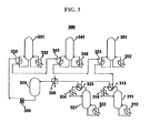
- FIG. 3 illustrates a process flow of the waste heat recovery network according to the present invention comprising both a waste heat recovery network and a waste heat utilization network.
- the multistage waste heat recovery system 300 comprises a first column 311, a first steam reboiler 312 for supplying heat to the first column wherein the first steam reboiler is connected to a lower part of the first column, a first hot water generator 313 for heating cold water to hot water by a hot fluid discharged from an upper part of the first column wherein the first hot water generator is connected to the upper part of the first column, a second column 321, a second steam reboiler 322 for supplying heat to the second column wherein the second steam reboiler is connected to a lower part of the second column, a second hot water generator 323 for heating the hot water produced in the first hot water generator to a higher temperature by a hot fluid discharged from an upper part of said second column wherein the second hot water generator is connected to the second column and the
- the multistage waste heat recovery system may further comprise one or more of a waste recovery device 360 for recovering waste heat from waste gas generated in the process with an intermediate temperature, a storage device 370 for storing hot water collected in the waste heat recovery network, a hot water feeding device 380 for supplying hot water collected in the storage device to the waste heat utilization network, cooling devices 314, 324 in preparation for the operation of the hot water generators being halted.
- a waste recovery device 360 for recovering waste heat from waste gas generated in the process with an intermediate temperature
- a storage device 370 for storing hot water collected in the waste heat recovery network
- a hot water feeding device 380 for supplying hot water collected in the storage device to the waste heat utilization network
- cooling devices 314, 324 in preparation for the operation of the hot water generators being halted.
- the temperatures in the waste heat recovery network is in the order of the temperature of intermediate-temperature waste gas > the operating temperature of the second column > the operating temperature of the first column; the temperatures in the waste heat utilization network is in the order of the operating temperature of the third column > the operating temperature of the fourth column > the operating temperature of the fifth column.
- the waste heat recovery system 300 as illustrated in FIG. 3 comprises (a) a waste heat recovery network comprising two waste heat recovery units consisting of columns, steam reboilers and hot water generators, and (b) a waste heat utilization network comprising three waste heat utilization units consisting of columns, steam reboilers and hot water reboilers.
- the number of units constituting the waste heat recovery network and the waste heat utilization network can be adjusted depending on the process conditions in various industries.
- the multistage waste heat recovery system can improve the energy recovery efficiency by obtaining hot water at higher temperatures through the waste heat recovery network and by utilizing hot water having relatively lower temperatures through the waste heat utilization network.
- the system recovers waste heat first from a column operated at a relatively low temperature and then from another column operated at a relatively high temperature so as to maximize the waste heat recovery.
- the system supplies heat first to a reboiler connected to a column operated at a relatively high temperature and then to another reboiler connected to a column operated at a relatively low temperature in order to maximize the waste heat utilization.
- each column must be operated at a constant temperature.
- a hot water reboiler it is preferable to supply a certain amount of heat by a hot water reboiler and to finely control the temperature of each column by a steam reboiler.
- the reboiler mostly utilizes the latent heat of steam; thus, the flow rate of steam only needs to be controlled.
- hot water it is preferable to control the temperature as well as the flow rate of hot water since the reboiler utilizes the sensible heat of hot water.
- the waste heat recovery system may further comprise a controller, which measures the flow rates and the temperatures of hot water fed to and discharged from the hot water reboiler and, based on their differences, controls either or both of the flow rate and the temperature of hot water fed to the hot water reboiler.
- FIG. 4 is a process flow diagram of the waste heat recovery system according to one embodiment of the present invention.
- the waste heat recovery system 400 according to one embodiment of the present invention comprises a column 401, a steam reboiler 402 for supplying heat wherein the steam reboiler is connected to a lower part of the column, a hot water reboiler 403 for supplying heat from the hot water produced in a hot water generator (not shown) to a lower part of the column wherein the hot water reboiler is connected to the hot water generator and the lower part of the column, and a controller 404 that measures the flow rate and the temperature of hot water fed to and discharged from the hot water reboiler 403 and calculates their differences for controlling either or both of the flow rate and the temperature of hot water fed to the hot water reboiler 403.
- the controller 404 may control the flow rate by a split range control method. Especially, in case the amount of heat supplied by hot water exceeds the total amount of heat required for the operation of the column, the split range control method not only reduces the amount of heat supplied by the steam reboiler to zero, but also increases the amount of hot water bypassed for reducing the amount of heat supplied by hot water.
- the waste heat recovery system of the present invention utilizes heat discharged from a distillation column, an incinerator, etc., to produce hot water and recovers heat at relatively low temperatures in high efficiency. Also, the investment and operating costs of the waste heat recovery system are relatively low as compared with the conventional systems. Therefore, it can be used in various industrial fields.
- waste heat recovery rate and the waste heat utilization rate can be enhanced by combining a number of columns operated at different temperatures.
- hot water having lower temperatures can be utilized, and waste heat can be recovered from a column operated at lower temperatures since the final temperature of hot water in the waste heat utilization network decreases.
- waste heat recovery system of the present invention uses a welded plate heat exchanger as a heat exchanger for the hot water reboiler such that the installation space and costs thereof can be significantly reduced.
- the multistage heat exchange system has advantages of maximizing the thermal efficiency of hot water and recovering waste heat from low-temperature heat sources by lowering the temperature as much as possible.
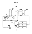
- the waste heat recovery system as illustrated in FIG. 5 was employed for recovering waste heat.
- waste heat generated from a column 531, an incinerator 532, a cooler 533, and a column 534 was recovered and supplied to a hot water generator 530 to produce hot water, which was stored in a storage device 540.
- the temperature of hot water sampled from the storage device 540 was 116°C.
- the hot water at 116°C supplied heat to a hot water reboiler 513 of a first column 511 (operating temperature: 77°C) via a hot water feeder 550 at a flow rate of 150 t/h.
- the flow rate and the temperature of the hot water fed to the hot water reboiler 513 were controlled by a controller 560.
- the hot water then supplied heat to a second column 521 (operating temperature: 58°C) by preheating the feed to the second column 521 by a hot water reboiler 523.
- the hot water discharged from the second column 521 at 82°C was then recycled to the hot water generator 530.
- the amounts of steam used in the steam reboiler of the first column 511 and the second column 521 were reduced by 6 t/h and 1.5 t/h, respectively.
Landscapes
- Engineering & Computer Science (AREA)
- Chemical & Material Sciences (AREA)
- Mechanical Engineering (AREA)
- General Engineering & Computer Science (AREA)
- Combustion & Propulsion (AREA)
- Chemical Kinetics & Catalysis (AREA)
- Environmental & Geological Engineering (AREA)
- Physics & Mathematics (AREA)
- Thermal Sciences (AREA)
- Water Supply & Treatment (AREA)
- Vaporization, Distillation, Condensation, Sublimation, And Cold Traps (AREA)
- Waste-Gas Treatment And Other Accessory Devices For Furnaces (AREA)
- Heat Treatment Of Water, Waste Water Or Sewage (AREA)
- Heat-Exchange Devices With Radiators And Conduit Assemblies (AREA)
Applications Claiming Priority (2)
| Application Number | Priority Date | Filing Date | Title |
|---|---|---|---|
| KR1020090123498A KR101172422B1 (ko) | 2009-12-11 | 2009-12-11 | 폐열 회수 시스템 |
| EP10836164.3A EP2511641A4 (de) | 2009-12-11 | 2010-11-30 | System zur rückgewinnung von abwärme |
Related Parent Applications (1)
| Application Number | Title | Priority Date | Filing Date |
|---|---|---|---|
| EP10836164.3A Division EP2511641A4 (de) | 2009-12-11 | 2010-11-30 | System zur rückgewinnung von abwärme |
Publications (3)
| Publication Number | Publication Date |
|---|---|
| EP2840343A2 true EP2840343A2 (de) | 2015-02-25 |
| EP2840343A3 EP2840343A3 (de) | 2015-04-22 |
| EP2840343B1 EP2840343B1 (de) | 2017-06-28 |
Family
ID=44146019
Family Applications (3)
| Application Number | Title | Priority Date | Filing Date |
|---|---|---|---|
| EP14193505.6A Not-in-force EP2840343B1 (de) | 2009-12-11 | 2010-11-30 | Abwärmerückgewinnungssystem |
| EP14193305.1A Not-in-force EP2860482B1 (de) | 2009-12-11 | 2010-11-30 | Abwärmerückgewinnungssystem |
| EP10836164.3A Withdrawn EP2511641A4 (de) | 2009-12-11 | 2010-11-30 | System zur rückgewinnung von abwärme |
Family Applications After (2)
| Application Number | Title | Priority Date | Filing Date |
|---|---|---|---|
| EP14193305.1A Not-in-force EP2860482B1 (de) | 2009-12-11 | 2010-11-30 | Abwärmerückgewinnungssystem |
| EP10836164.3A Withdrawn EP2511641A4 (de) | 2009-12-11 | 2010-11-30 | System zur rückgewinnung von abwärme |
Country Status (7)
| Country | Link |
|---|---|
| US (1) | US9574829B2 (de) |
| EP (3) | EP2840343B1 (de) |
| JP (1) | JP5542958B2 (de) |
| KR (1) | KR101172422B1 (de) |
| CN (1) | CN102656416B (de) |
| HU (1) | HUE038760T2 (de) |
| WO (1) | WO2011071268A2 (de) |
Families Citing this family (13)
| Publication number | Priority date | Publication date | Assignee | Title |
|---|---|---|---|---|
| KR101172422B1 (ko) | 2009-12-11 | 2012-08-08 | 에스케이씨 주식회사 | 폐열 회수 시스템 |
| US20140196499A1 (en) * | 2013-01-14 | 2014-07-17 | Alstom Technology Ltd. | Stripper overhead heat integration system for reduction of energy consumption |
| CN104215095A (zh) * | 2014-09-25 | 2014-12-17 | 无锡昊瑜节能环保设备有限公司 | 一种废水热能回收系统 |
| CN106567750A (zh) * | 2015-10-13 | 2017-04-19 | 四川新玛能源科技有限公司 | 一种煤制油工艺凝液余热高效利用系统 |
| CN105822359A (zh) * | 2016-05-20 | 2016-08-03 | 山东京博石油化工有限公司 | 一种蒸汽能量多级利用工艺 |
| EP3421426A1 (de) * | 2017-06-29 | 2019-01-02 | Covestro Deutschland AG | Energieeffizientes verfahren zur bereitstellung von phosgen-dampf |
| US10508568B2 (en) * | 2018-03-16 | 2019-12-17 | Uop Llc | Process improvement through the addition of power recovery turbine equipment in existing processes |
| CN110280032A (zh) * | 2019-07-29 | 2019-09-27 | 唐俊 | 一种用于高温烟气中能量、水分及粉尘的回收系统 |
| CN113877227B (zh) * | 2021-09-28 | 2022-09-30 | 常州瑞华化工工程技术股份有限公司 | 一种降膜式再沸器和热泵技术组合提供分离塔所需热源的苯乙烯精制方法 |
| WO2023148605A1 (en) | 2022-02-01 | 2023-08-10 | CRI, hf | Heat integration |
| US12455098B2 (en) | 2022-04-12 | 2025-10-28 | The Cleaver-Brooks Company, Inc. | Thermal efficiency system and method for boiler plant |
| KR102848435B1 (ko) | 2022-07-07 | 2025-08-20 | 대흥산업가스 주식회사 | 하이브리드 열교환 방식의 리보일러 |
| CN119868993B (zh) * | 2025-03-28 | 2025-06-10 | 齐成(山东)石化集团有限公司 | 一种抽提精馏装置 |
Family Cites Families (34)
| Publication number | Priority date | Publication date | Assignee | Title |
|---|---|---|---|---|
| GB776154A (en) * | 1952-12-19 | 1957-06-05 | Ruetgerswerke Ag | Improvements in and relating to the fractional distillation of mixtures of liquids |
| CH353335A (de) * | 1957-09-10 | 1961-04-15 | Escher Wyss Ag | Verfahren und Einrichtung zur Eindampfung einer Lösung |
| DE1165549B (de) * | 1962-03-16 | 1964-03-19 | Bayer Ag | Rektifizierverfahren |
| US3261766A (en) * | 1964-12-11 | 1966-07-19 | Fluor Corp | Multistage evaporation with absorption of distilled vapors |
| US3597465A (en) * | 1968-03-04 | 1971-08-03 | Chemical Construction Corp | Production of synthetic methanol |
| US3904656A (en) * | 1973-02-13 | 1975-09-09 | Ppg Industries Inc | Process for preparing monoethylene glycol and ethylene oxide |
| IN148355B (de) * | 1977-03-11 | 1981-01-24 | Ici Ltd | |
| US4160810A (en) * | 1978-03-07 | 1979-07-10 | Benfield Corporation | Removal of acid gases from hot gas mixtures |
| FR2482979A1 (fr) * | 1980-05-22 | 1981-11-27 | Commissariat Energie Atomique | Procede de distillation de l'alcool comportant l'utilisation d'une pompe a chaleur, et dispositif de mise en oeuvre de ce procede |
| US4638765A (en) * | 1985-10-24 | 1987-01-27 | Foster Wheeler Energy Corporation | Heat recovery system |
| US5035776A (en) * | 1990-03-29 | 1991-07-30 | University Of Massachusetts | Low energy extractive distillation process for producing anhydrous ethanol |
| KR100271115B1 (ko) * | 1992-07-24 | 2000-11-01 | 데이보드 테이저-아르데빌리 | 물 증류 시스템 |
| DE4235431C1 (de) * | 1992-10-21 | 1994-01-20 | Huels Chemische Werke Ag | Verfahren zur Trennung von Ethylbenzol/Styrol durch Destillation eines flüssigen, überwiegend aus Styrol und Ethylbenzol bestehenden Gemisches |
| JP3594252B2 (ja) * | 1994-07-11 | 2004-11-24 | 東京瓦斯株式会社 | コージェネレーションシステム |
| US5953936A (en) * | 1997-10-28 | 1999-09-21 | Air Products And Chemicals, Inc. | Distillation process to separate mixtures containing three or more components |
| EP0965373B1 (de) * | 1998-06-17 | 2004-08-11 | Sulzer Chemtech AG | Destillationsanlage mit Kolonne und Wärmepumpe. |
| US6291734B1 (en) * | 1999-06-16 | 2001-09-18 | Kellogg Brown & Root, Inc. | Integrated low pressure depropanizer/debutanizer column |
| JP2001035520A (ja) * | 1999-07-26 | 2001-02-09 | Fuji Electric Co Ltd | 燃料電池発電装置の廃熱利用装置 |
| JP4495279B2 (ja) * | 1999-10-12 | 2010-06-30 | 大陽日酸株式会社 | 蒸留装置並びに酸素同位体重成分の濃縮方法および重酸素水の製造方法 |
| FR2803221B1 (fr) | 1999-12-30 | 2002-03-29 | Air Liquide | Procede et installation de separation d'air |
| JP3505503B2 (ja) * | 2000-11-22 | 2004-03-08 | 康一 浅野 | 分離係数が1に近い混合物の蒸留による分離濃縮方法および装置 |
| FR2855170B1 (fr) * | 2003-05-21 | 2006-07-28 | Ungda | Procede de deshydratation d'ethanol et de flegmes ethanoliques par distillation azeotropique en economie d'energie |
| KR100561975B1 (ko) * | 2004-05-10 | 2006-03-22 | 최동순 | 열발생로의 폐열 회수장치 |
| KR100678705B1 (ko) * | 2005-02-05 | 2007-02-02 | 황치원 | 증기동력플랜트의 폐열회수장치 |
| KR100681240B1 (ko) * | 2005-12-06 | 2007-02-09 | 삼성정밀화학 주식회사 | 폐열을 이용한 공정배관 보온용 열교환기를 가지는 요소플랜트의 공정가스 회수 설비 |
| JP4884030B2 (ja) | 2006-03-06 | 2012-02-22 | 大阪瓦斯株式会社 | 熱電併給システム |
| JP2007247932A (ja) * | 2006-03-14 | 2007-09-27 | Chugoku Electric Power Co Inc:The | 自動車の廃熱利用温水生成装置及び方法 |
| JP4990008B2 (ja) * | 2007-04-10 | 2012-08-01 | 株式会社神戸製鋼所 | 蒸気処理設備 |
| CN101165399B (zh) * | 2007-08-07 | 2010-11-03 | 江苏工业学院 | 锅炉低品位余热联合回收方法及装置 |
| DE102008013933A1 (de) * | 2008-03-12 | 2009-11-05 | Areva Np Gmbh | Verfahren und Vorrichtung zum Abtrennen eines Neutronenabsorbers von einem Kühlmittel eines Kühlkreislaufes |
| CN201327047Y (zh) * | 2008-10-22 | 2009-10-14 | 信羚源股份有限公司 | 锅炉烟囱废热回收装置 |
| US8999117B2 (en) * | 2009-03-04 | 2015-04-07 | Uop Llc | Process and system for heating or cooling streams for a divided distillation column |
| KR101172422B1 (ko) | 2009-12-11 | 2012-08-08 | 에스케이씨 주식회사 | 폐열 회수 시스템 |
| WO2014074261A1 (en) * | 2012-11-07 | 2014-05-15 | Lummus Technology Inc. | Selective olefin extraction |
-
2009
- 2009-12-11 KR KR1020090123498A patent/KR101172422B1/ko not_active Expired - Fee Related
-
2010
- 2010-11-30 JP JP2012543015A patent/JP5542958B2/ja not_active Expired - Fee Related
- 2010-11-30 EP EP14193505.6A patent/EP2840343B1/de not_active Not-in-force
- 2010-11-30 EP EP14193305.1A patent/EP2860482B1/de not_active Not-in-force
- 2010-11-30 WO PCT/KR2010/008521 patent/WO2011071268A2/ko not_active Ceased
- 2010-11-30 HU HUE14193305A patent/HUE038760T2/hu unknown
- 2010-11-30 US US13/514,857 patent/US9574829B2/en not_active Expired - Fee Related
- 2010-11-30 EP EP10836164.3A patent/EP2511641A4/de not_active Withdrawn
- 2010-11-30 CN CN201080055927.5A patent/CN102656416B/zh not_active Expired - Fee Related
Non-Patent Citations (1)
| Title |
|---|
| None |
Also Published As
| Publication number | Publication date |
|---|---|
| EP2860482B1 (de) | 2018-03-28 |
| JP2013513085A (ja) | 2013-04-18 |
| KR101172422B1 (ko) | 2012-08-08 |
| EP2860482A3 (de) | 2015-04-22 |
| CN102656416B (zh) | 2014-06-25 |
| WO2011071268A2 (ko) | 2011-06-16 |
| EP2511641A4 (de) | 2014-05-14 |
| EP2840343A3 (de) | 2015-04-22 |
| EP2511641A2 (de) | 2012-10-17 |
| EP2840343B1 (de) | 2017-06-28 |
| WO2011071268A3 (ko) | 2011-11-03 |
| US9574829B2 (en) | 2017-02-21 |
| CN102656416A (zh) | 2012-09-05 |
| JP5542958B2 (ja) | 2014-07-09 |
| US20120267076A1 (en) | 2012-10-25 |
| HUE038760T2 (hu) | 2018-11-28 |
| KR20110066733A (ko) | 2011-06-17 |
| EP2860482A2 (de) | 2015-04-15 |
Similar Documents
| Publication | Publication Date | Title |
|---|---|---|
| EP2860482B1 (de) | Abwärmerückgewinnungssystem | |
| KR102787291B1 (ko) | 화학 물질의 생성에서 간헐적 에너지의 사용 | |
| Sharan et al. | Optimal feed flow sequence for multi-effect distillation system integrated with supercritical carbon dioxide Brayton cycle for seawater desalination | |
| JP7391071B2 (ja) | 排熱利用システム | |
| WO2019177464A1 (en) | A system for recovery of waste heat from an industrial plant | |
| US10443932B2 (en) | Refrigerant vent rectifier and efficiency booster | |
| KR890004398B1 (ko) | 가스 분리방법 및 장치 | |
| CN108675656B (zh) | 一种利用回收二氧化碳发电的电烧石灰窑 | |
| JPH11223417A (ja) | 製鉄プロセスから発生する低温排熱の回収方法 | |
| CN106705013B (zh) | 基于多压模式的电炉烟气余热利用系统 | |
| KR20090008124A (ko) | 이중 압력 다단계 전기 분해를 이용하는 수소 생성 공정 | |
| EP3725400A1 (de) | Verwendung von intermittierender energie bei der herstellung von chemikalien | |
| CN113440882B (zh) | 一种应用于苯乙烯分离系统的装置及方法 | |
| Gadalla et al. | A design method for internal heat integrated distillation columns (iHIDiCs) | |
| CN219355278U (zh) | 一种精馏塔顶余热回收系统 | |
| CN113405395A (zh) | 一种冷却和热回收综合利用系统 | |
| CN216725796U (zh) | 低能耗的低温蒸发装置 | |
| KR20250098327A (ko) | 공정 유체 처리 시스템 | |
| KR20250045596A (ko) | 열통합 증류 방법 | |
| EP3725399A1 (de) | Verwendung von intermittierender energie bei der herstellung von chemikalien | |
| CN121466622A (zh) | 一种集成公用工程管网的低成本高能量利用率精馏系统及操作方法 | |
| Xu et al. | Exergy analysis and performance enhancement of isopropanol-acetone-hydrogen chemical heat pump | |
| JPWO2014196611A1 (ja) | 濃縮装置および濃縮方法 | |
| KR20130051699A (ko) | 에너지 효율이 높은 중합 반응기의 열교환 시스템 및 그 장치 | |
| JP2003146936A (ja) | (メタ)アクリル酸類の製造方法 |
Legal Events
| Date | Code | Title | Description |
|---|---|---|---|
| PUAI | Public reference made under article 153(3) epc to a published international application that has entered the european phase |
Free format text: ORIGINAL CODE: 0009012 |
|
| 17P | Request for examination filed |
Effective date: 20141117 |
|
| AC | Divisional application: reference to earlier application |
Ref document number: 2511641 Country of ref document: EP Kind code of ref document: P |
|
| AK | Designated contracting states |
Kind code of ref document: A2 Designated state(s): AL AT BE BG CH CY CZ DE DK EE ES FI FR GB GR HR HU IE IS IT LI LT LU LV MC MK MT NL NO PL PT RO RS SE SI SK SM TR |
|
| PUAL | Search report despatched |
Free format text: ORIGINAL CODE: 0009013 |
|
| AK | Designated contracting states |
Kind code of ref document: A3 Designated state(s): AL AT BE BG CH CY CZ DE DK EE ES FI FR GB GR HR HU IE IS IT LI LT LU LV MC MK MT NL NO PL PT RO RS SE SI SK SM TR |
|
| RIC1 | Information provided on ipc code assigned before grant |
Ipc: F01K 23/06 20060101ALI20150316BHEP Ipc: F01K 17/02 20060101ALI20150316BHEP Ipc: F01K 17/06 20060101ALI20150316BHEP Ipc: B01D 3/00 20060101ALI20150316BHEP Ipc: B01D 1/00 20060101ALI20150316BHEP Ipc: F28D 21/00 20060101ALI20150316BHEP Ipc: F28D 15/00 20060101ALI20150316BHEP Ipc: F28D 7/00 20060101AFI20150316BHEP Ipc: B01D 1/28 20060101ALI20150316BHEP Ipc: F27D 17/00 20060101ALI20150316BHEP |
|
| R17P | Request for examination filed (corrected) |
Effective date: 20151021 |
|
| RBV | Designated contracting states (corrected) |
Designated state(s): AL AT BE BG CH CY CZ DE DK EE ES FI FR GB GR HR HU IE IS IT LI LT LU LV MC MK MT NL NO PL PT RO RS SE SI SK SM TR |
|
| GRAP | Despatch of communication of intention to grant a patent |
Free format text: ORIGINAL CODE: EPIDOSNIGR1 |
|
| INTG | Intention to grant announced |
Effective date: 20170303 |
|
| GRAS | Grant fee paid |
Free format text: ORIGINAL CODE: EPIDOSNIGR3 |
|
| GRAA | (expected) grant |
Free format text: ORIGINAL CODE: 0009210 |
|
| AC | Divisional application: reference to earlier application |
Ref document number: 2511641 Country of ref document: EP Kind code of ref document: P |
|
| AK | Designated contracting states |
Kind code of ref document: B1 Designated state(s): AL AT BE BG CH CY CZ DE DK EE ES FI FR GB GR HR HU IE IS IT LI LT LU LV MC MK MT NL NO PL PT RO RS SE SI SK SM TR |
|
| REG | Reference to a national code |
Ref country code: GB Ref legal event code: FG4D |
|
| REG | Reference to a national code |
Ref country code: CH Ref legal event code: EP |
|
| REG | Reference to a national code |
Ref country code: AT Ref legal event code: REF Ref document number: 905259 Country of ref document: AT Kind code of ref document: T Effective date: 20170715 |
|
| REG | Reference to a national code |
Ref country code: IE Ref legal event code: FG4D |
|
| REG | Reference to a national code |
Ref country code: DE Ref legal event code: R096 Ref document number: 602010043377 Country of ref document: DE |
|
| PG25 | Lapsed in a contracting state [announced via postgrant information from national office to epo] |
Ref country code: GR Free format text: LAPSE BECAUSE OF FAILURE TO SUBMIT A TRANSLATION OF THE DESCRIPTION OR TO PAY THE FEE WITHIN THE PRESCRIBED TIME-LIMIT Effective date: 20170929 Ref country code: NO Free format text: LAPSE BECAUSE OF FAILURE TO SUBMIT A TRANSLATION OF THE DESCRIPTION OR TO PAY THE FEE WITHIN THE PRESCRIBED TIME-LIMIT Effective date: 20170928 Ref country code: FI Free format text: LAPSE BECAUSE OF FAILURE TO SUBMIT A TRANSLATION OF THE DESCRIPTION OR TO PAY THE FEE WITHIN THE PRESCRIBED TIME-LIMIT Effective date: 20170628 Ref country code: LT Free format text: LAPSE BECAUSE OF FAILURE TO SUBMIT A TRANSLATION OF THE DESCRIPTION OR TO PAY THE FEE WITHIN THE PRESCRIBED TIME-LIMIT Effective date: 20170628 Ref country code: HR Free format text: LAPSE BECAUSE OF FAILURE TO SUBMIT A TRANSLATION OF THE DESCRIPTION OR TO PAY THE FEE WITHIN THE PRESCRIBED TIME-LIMIT Effective date: 20170628 |
|
| REG | Reference to a national code |
Ref country code: NL Ref legal event code: MP Effective date: 20170628 |
|
| REG | Reference to a national code |
Ref country code: LT Ref legal event code: MG4D |
|
| REG | Reference to a national code |
Ref country code: AT Ref legal event code: MK05 Ref document number: 905259 Country of ref document: AT Kind code of ref document: T Effective date: 20170628 |
|
| PG25 | Lapsed in a contracting state [announced via postgrant information from national office to epo] |
Ref country code: LV Free format text: LAPSE BECAUSE OF FAILURE TO SUBMIT A TRANSLATION OF THE DESCRIPTION OR TO PAY THE FEE WITHIN THE PRESCRIBED TIME-LIMIT Effective date: 20170628 Ref country code: BG Free format text: LAPSE BECAUSE OF FAILURE TO SUBMIT A TRANSLATION OF THE DESCRIPTION OR TO PAY THE FEE WITHIN THE PRESCRIBED TIME-LIMIT Effective date: 20170928 Ref country code: RS Free format text: LAPSE BECAUSE OF FAILURE TO SUBMIT A TRANSLATION OF THE DESCRIPTION OR TO PAY THE FEE WITHIN THE PRESCRIBED TIME-LIMIT Effective date: 20170628 Ref country code: NL Free format text: LAPSE BECAUSE OF FAILURE TO SUBMIT A TRANSLATION OF THE DESCRIPTION OR TO PAY THE FEE WITHIN THE PRESCRIBED TIME-LIMIT Effective date: 20170628 Ref country code: SE Free format text: LAPSE BECAUSE OF FAILURE TO SUBMIT A TRANSLATION OF THE DESCRIPTION OR TO PAY THE FEE WITHIN THE PRESCRIBED TIME-LIMIT Effective date: 20170628 |
|
| PG25 | Lapsed in a contracting state [announced via postgrant information from national office to epo] |
Ref country code: EE Free format text: LAPSE BECAUSE OF FAILURE TO SUBMIT A TRANSLATION OF THE DESCRIPTION OR TO PAY THE FEE WITHIN THE PRESCRIBED TIME-LIMIT Effective date: 20170628 Ref country code: SK Free format text: LAPSE BECAUSE OF FAILURE TO SUBMIT A TRANSLATION OF THE DESCRIPTION OR TO PAY THE FEE WITHIN THE PRESCRIBED TIME-LIMIT Effective date: 20170628 Ref country code: CZ Free format text: LAPSE BECAUSE OF FAILURE TO SUBMIT A TRANSLATION OF THE DESCRIPTION OR TO PAY THE FEE WITHIN THE PRESCRIBED TIME-LIMIT Effective date: 20170628 Ref country code: RO Free format text: LAPSE BECAUSE OF FAILURE TO SUBMIT A TRANSLATION OF THE DESCRIPTION OR TO PAY THE FEE WITHIN THE PRESCRIBED TIME-LIMIT Effective date: 20170628 Ref country code: AT Free format text: LAPSE BECAUSE OF FAILURE TO SUBMIT A TRANSLATION OF THE DESCRIPTION OR TO PAY THE FEE WITHIN THE PRESCRIBED TIME-LIMIT Effective date: 20170628 |
|
| PG25 | Lapsed in a contracting state [announced via postgrant information from national office to epo] |
Ref country code: SM Free format text: LAPSE BECAUSE OF FAILURE TO SUBMIT A TRANSLATION OF THE DESCRIPTION OR TO PAY THE FEE WITHIN THE PRESCRIBED TIME-LIMIT Effective date: 20170628 Ref country code: IS Free format text: LAPSE BECAUSE OF FAILURE TO SUBMIT A TRANSLATION OF THE DESCRIPTION OR TO PAY THE FEE WITHIN THE PRESCRIBED TIME-LIMIT Effective date: 20171028 Ref country code: IT Free format text: LAPSE BECAUSE OF FAILURE TO SUBMIT A TRANSLATION OF THE DESCRIPTION OR TO PAY THE FEE WITHIN THE PRESCRIBED TIME-LIMIT Effective date: 20170628 Ref country code: ES Free format text: LAPSE BECAUSE OF FAILURE TO SUBMIT A TRANSLATION OF THE DESCRIPTION OR TO PAY THE FEE WITHIN THE PRESCRIBED TIME-LIMIT Effective date: 20170628 Ref country code: PL Free format text: LAPSE BECAUSE OF FAILURE TO SUBMIT A TRANSLATION OF THE DESCRIPTION OR TO PAY THE FEE WITHIN THE PRESCRIBED TIME-LIMIT Effective date: 20170628 |
|
| REG | Reference to a national code |
Ref country code: DE Ref legal event code: R097 Ref document number: 602010043377 Country of ref document: DE |
|
| PG25 | Lapsed in a contracting state [announced via postgrant information from national office to epo] |
Ref country code: DK Free format text: LAPSE BECAUSE OF FAILURE TO SUBMIT A TRANSLATION OF THE DESCRIPTION OR TO PAY THE FEE WITHIN THE PRESCRIBED TIME-LIMIT Effective date: 20170628 |
|
| PLBE | No opposition filed within time limit |
Free format text: ORIGINAL CODE: 0009261 |
|
| STAA | Information on the status of an ep patent application or granted ep patent |
Free format text: STATUS: NO OPPOSITION FILED WITHIN TIME LIMIT |
|
| 26N | No opposition filed |
Effective date: 20180329 |
|
| PG25 | Lapsed in a contracting state [announced via postgrant information from national office to epo] |
Ref country code: MC Free format text: LAPSE BECAUSE OF FAILURE TO SUBMIT A TRANSLATION OF THE DESCRIPTION OR TO PAY THE FEE WITHIN THE PRESCRIBED TIME-LIMIT Effective date: 20170628 |
|
| GBPC | Gb: european patent ceased through non-payment of renewal fee |
Effective date: 20171130 |
|
| PG25 | Lapsed in a contracting state [announced via postgrant information from national office to epo] |
Ref country code: LI Free format text: LAPSE BECAUSE OF NON-PAYMENT OF DUE FEES Effective date: 20171130 Ref country code: CH Free format text: LAPSE BECAUSE OF NON-PAYMENT OF DUE FEES Effective date: 20171130 |
|
| PG25 | Lapsed in a contracting state [announced via postgrant information from national office to epo] |
Ref country code: LU Free format text: LAPSE BECAUSE OF NON-PAYMENT OF DUE FEES Effective date: 20171130 Ref country code: SI Free format text: LAPSE BECAUSE OF FAILURE TO SUBMIT A TRANSLATION OF THE DESCRIPTION OR TO PAY THE FEE WITHIN THE PRESCRIBED TIME-LIMIT Effective date: 20170628 |
|
| REG | Reference to a national code |
Ref country code: FR Ref legal event code: ST Effective date: 20180731 Ref country code: BE Ref legal event code: MM Effective date: 20171130 |
|
| REG | Reference to a national code |
Ref country code: IE Ref legal event code: MM4A |
|
| PG25 | Lapsed in a contracting state [announced via postgrant information from national office to epo] |
Ref country code: MT Free format text: LAPSE BECAUSE OF NON-PAYMENT OF DUE FEES Effective date: 20171130 |
|
| PG25 | Lapsed in a contracting state [announced via postgrant information from national office to epo] |
Ref country code: FR Free format text: LAPSE BECAUSE OF NON-PAYMENT OF DUE FEES Effective date: 20171130 Ref country code: IE Free format text: LAPSE BECAUSE OF NON-PAYMENT OF DUE FEES Effective date: 20171130 |
|
| PG25 | Lapsed in a contracting state [announced via postgrant information from national office to epo] |
Ref country code: GB Free format text: LAPSE BECAUSE OF NON-PAYMENT OF DUE FEES Effective date: 20171130 Ref country code: BE Free format text: LAPSE BECAUSE OF NON-PAYMENT OF DUE FEES Effective date: 20171130 |
|
| PG25 | Lapsed in a contracting state [announced via postgrant information from national office to epo] |
Ref country code: HU Free format text: LAPSE BECAUSE OF FAILURE TO SUBMIT A TRANSLATION OF THE DESCRIPTION OR TO PAY THE FEE WITHIN THE PRESCRIBED TIME-LIMIT; INVALID AB INITIO Effective date: 20101130 |
|
| PG25 | Lapsed in a contracting state [announced via postgrant information from national office to epo] |
Ref country code: CY Free format text: LAPSE BECAUSE OF FAILURE TO SUBMIT A TRANSLATION OF THE DESCRIPTION OR TO PAY THE FEE WITHIN THE PRESCRIBED TIME-LIMIT Effective date: 20170628 |
|
| PG25 | Lapsed in a contracting state [announced via postgrant information from national office to epo] |
Ref country code: MK Free format text: LAPSE BECAUSE OF FAILURE TO SUBMIT A TRANSLATION OF THE DESCRIPTION OR TO PAY THE FEE WITHIN THE PRESCRIBED TIME-LIMIT Effective date: 20170628 |
|
| REG | Reference to a national code |
Ref country code: DE Ref legal event code: R082 Ref document number: 602010043377 Country of ref document: DE Ref country code: DE Ref legal event code: R081 Ref document number: 602010043377 Country of ref document: DE Owner name: SK PICGLOBAL CO., LTD., KR Free format text: FORMER OWNER: SKC CO., LTD., SUWON-SI, KR |
|
| PG25 | Lapsed in a contracting state [announced via postgrant information from national office to epo] |
Ref country code: TR Free format text: LAPSE BECAUSE OF FAILURE TO SUBMIT A TRANSLATION OF THE DESCRIPTION OR TO PAY THE FEE WITHIN THE PRESCRIBED TIME-LIMIT Effective date: 20170628 |
|
| PG25 | Lapsed in a contracting state [announced via postgrant information from national office to epo] |
Ref country code: PT Free format text: LAPSE BECAUSE OF FAILURE TO SUBMIT A TRANSLATION OF THE DESCRIPTION OR TO PAY THE FEE WITHIN THE PRESCRIBED TIME-LIMIT Effective date: 20170628 |
|
| PG25 | Lapsed in a contracting state [announced via postgrant information from national office to epo] |
Ref country code: AL Free format text: LAPSE BECAUSE OF FAILURE TO SUBMIT A TRANSLATION OF THE DESCRIPTION OR TO PAY THE FEE WITHIN THE PRESCRIBED TIME-LIMIT Effective date: 20170628 |
|
| P01 | Opt-out of the competence of the unified patent court (upc) registered |
Effective date: 20230614 |
|
| PGFP | Annual fee paid to national office [announced via postgrant information from national office to epo] |
Ref country code: DE Payment date: 20230920 Year of fee payment: 14 |
|
| REG | Reference to a national code |
Ref country code: DE Ref legal event code: R119 Ref document number: 602010043377 Country of ref document: DE |
|
| PG25 | Lapsed in a contracting state [announced via postgrant information from national office to epo] |
Ref country code: DE Free format text: LAPSE BECAUSE OF NON-PAYMENT OF DUE FEES Effective date: 20250603 |