EP2840323A2 - System and method for mounting undercabinet ventilation hood - Google Patents
System and method for mounting undercabinet ventilation hood Download PDFInfo
- Publication number
- EP2840323A2 EP2840323A2 EP14179018.8A EP14179018A EP2840323A2 EP 2840323 A2 EP2840323 A2 EP 2840323A2 EP 14179018 A EP14179018 A EP 14179018A EP 2840323 A2 EP2840323 A2 EP 2840323A2
- Authority
- EP
- European Patent Office
- Prior art keywords
- ventilation hood
- brackets
- cabinet
- support
- support tabs
- Prior art date
- Legal status (The legal status is an assumption and is not a legal conclusion. Google has not performed a legal analysis and makes no representation as to the accuracy of the status listed.)
- Granted
Links
- 238000009423 ventilation Methods 0.000 title claims abstract description 82
- 238000000034 method Methods 0.000 title claims description 20
- 238000010411 cooking Methods 0.000 claims description 21
- 238000005452 bending Methods 0.000 claims description 4
- 125000006850 spacer group Chemical group 0.000 claims description 4
- 239000006227 byproduct Substances 0.000 description 5
- 239000002184 metal Substances 0.000 description 4
- 238000010276 construction Methods 0.000 description 3
- 239000000945 filler Substances 0.000 description 3
- 239000000463 material Substances 0.000 description 3
- 239000000779 smoke Substances 0.000 description 3
- 238000005553 drilling Methods 0.000 description 2
- 239000004519 grease Substances 0.000 description 2
- 238000010438 heat treatment Methods 0.000 description 2
- 230000000712 assembly Effects 0.000 description 1
- 238000000429 assembly Methods 0.000 description 1
- 230000001627 detrimental effect Effects 0.000 description 1
- 238000009432 framing Methods 0.000 description 1
- 239000000446 fuel Substances 0.000 description 1
- 238000009434 installation Methods 0.000 description 1
- 238000004519 manufacturing process Methods 0.000 description 1
- 238000012986 modification Methods 0.000 description 1
- 230000004048 modification Effects 0.000 description 1
- 239000000047 product Substances 0.000 description 1
- 230000001105 regulatory effect Effects 0.000 description 1
- 230000000717 retained effect Effects 0.000 description 1
- 238000007493 shaping process Methods 0.000 description 1
- 230000000007 visual effect Effects 0.000 description 1
- 239000002023 wood Substances 0.000 description 1
Images


Classifications
-
- F—MECHANICAL ENGINEERING; LIGHTING; HEATING; WEAPONS; BLASTING
- F24—HEATING; RANGES; VENTILATING
- F24C—DOMESTIC STOVES OR RANGES ; DETAILS OF DOMESTIC STOVES OR RANGES, OF GENERAL APPLICATION
- F24C15/00—Details
- F24C15/20—Removing cooking fumes
- F24C15/2071—Removing cooking fumes mounting of cooking hood
-
- F—MECHANICAL ENGINEERING; LIGHTING; HEATING; WEAPONS; BLASTING
- F24—HEATING; RANGES; VENTILATING
- F24F—AIR-CONDITIONING; AIR-HUMIDIFICATION; VENTILATION; USE OF AIR CURRENTS FOR SCREENING
- F24F13/00—Details common to, or for air-conditioning, air-humidification, ventilation or use of air currents for screening
- F24F13/02—Ducting arrangements
- F24F13/0254—Ducting arrangements characterised by their mounting means, e.g. supports
-
- Y—GENERAL TAGGING OF NEW TECHNOLOGICAL DEVELOPMENTS; GENERAL TAGGING OF CROSS-SECTIONAL TECHNOLOGIES SPANNING OVER SEVERAL SECTIONS OF THE IPC; TECHNICAL SUBJECTS COVERED BY FORMER USPC CROSS-REFERENCE ART COLLECTIONS [XRACs] AND DIGESTS
- Y10—TECHNICAL SUBJECTS COVERED BY FORMER USPC
- Y10T—TECHNICAL SUBJECTS COVERED BY FORMER US CLASSIFICATION
- Y10T29/00—Metal working
- Y10T29/49—Method of mechanical manufacture
- Y10T29/49616—Structural member making
- Y10T29/49623—Static structure, e.g., a building component
-
- Y—GENERAL TAGGING OF NEW TECHNOLOGICAL DEVELOPMENTS; GENERAL TAGGING OF CROSS-SECTIONAL TECHNOLOGIES SPANNING OVER SEVERAL SECTIONS OF THE IPC; TECHNICAL SUBJECTS COVERED BY FORMER USPC CROSS-REFERENCE ART COLLECTIONS [XRACs] AND DIGESTS
- Y10—TECHNICAL SUBJECTS COVERED BY FORMER USPC
- Y10T—TECHNICAL SUBJECTS COVERED BY FORMER US CLASSIFICATION
- Y10T29/00—Metal working
- Y10T29/51—Plural diverse manufacturing apparatus including means for metal shaping or assembling
-
- Y—GENERAL TAGGING OF NEW TECHNOLOGICAL DEVELOPMENTS; GENERAL TAGGING OF CROSS-SECTIONAL TECHNOLOGIES SPANNING OVER SEVERAL SECTIONS OF THE IPC; TECHNICAL SUBJECTS COVERED BY FORMER USPC CROSS-REFERENCE ART COLLECTIONS [XRACs] AND DIGESTS
- Y10—TECHNICAL SUBJECTS COVERED BY FORMER USPC
- Y10T—TECHNICAL SUBJECTS COVERED BY FORMER US CLASSIFICATION
- Y10T29/00—Metal working
- Y10T29/53—Means to assemble or disassemble
Definitions
- the present invention pertains to the art of cooking and, more particularly, to a system and method for mounting a ventilation hood under cabinetry positioned above a cooking appliance.
- both types of ranges are designed to be situated in a space or cut-out provided along a length of a kitchen countertop.
- the range includes at least one oven cavity supported below a cooktop.
- cooktops without lower oven cavities, in countertops.
- a ventilation unit above the range.
- such known ventilation units include an exhaust fan which functions to draw the smoke and other byproducts away from the cooktop.
- the byproducts are typically either directed to a vent external of the cooking area or filtered such that the cleansed air is simply expelled back into the cooking area.
- Such known ventilation units can take the form of a ventilation hood or can be incorporated into an overhead microwave oven mounted above the range. In many situations, the ventilation unit will also incorporate a light to aid in illuminating the cooktop.
- a ventilation unit incorporated into a microwave oven In mounting a ventilation unit incorporated into a microwave oven to the bottom of a cabinet which is centered above and spans the appliance, it is commonplace to bolt the ventilation unit to a bottom cabinet panel. More specifically, a housing of the microwave oven is provided with spaced front and rear mounting holes and a template can be provided which enables an installer to mark drilling locations in the bottom panel of the cabinet, with the intent that the drilled holes will be aligned with pre-formed mounting holes in the unit. Assuming the proper alignment exists, the microwave oven can be held in a position beneath the upper cabinet and bolts inserted through each of the aligned hole sets to secure the microwave oven in place. In the case of a ventilation hood, the housing of the hood is typically used as a template for determining appropriate fastener locations and then filler strips are measured, cut and installed beneath the cabinet to complete lower framing needed to mount the ventilation hood.
- the present invention is directed to a system and method for mounting a ventilation hood above a cooking appliance and under a cabinet, such as in a kitchen.
- the system employs a pair of support brackets mounted to the underside of the cabinet at laterally spaced, left and right positions, with each support bracket including distinct aligning, positioning and hanging structure which enables a single person to readily mount the ventilation hood to the cabinet.
- each support bracket includes a main body from which depend at least one and, more preferably, first and second longitudinally spaced support tabs or hangers, as well as a locator tab.
- Alignment structure enables the main body to be easily positioned for mounting to the cabinet in a requisite manner, while the locator tab assures that the support bracket is positioned a required distance from a rear wall extending behind the cabinet.
- the ventilation hood can be positioned so that the support tab(s) is/are received in one or more slots formed in a top panel of the hood and, upon sliding the ventilation hood rearward, the hood rides upon ramped or tapered surface of each support tab to position the hood against the cabinet while hanging the hood from the support tab(s). Thereafter, the support tab(s) can be bent to retain the ventilation hood in an operational position. If desired, a mechanical fastener can be employed to secure each bent support tab to the ventilation hood.
- the support brackets are configured for use in mounting a ventilation hood beneath a frameless cabinet, i.e., a cabinet having supports above the bottom panel.
- each support bracket is provided with one or more support tabs or hangers which project perpendicular to the main body.
- the main body is again aligned, either visually or through the use of spacers and positioned from the rear wall by the locator tab.
- the support tab(s) employed with mounting the ventilation hood on a cabinet including a lower frame can be used as the lateral spacers.
- a corresponding hanging and securing operation for the ventilation hood can be readily effected by a single person.
- a cooking appliance 2 is shown positioned in a cut-out or opening 5 provided in a countertop 8 and between adjacent lower cabinetry 12 and 13.
- Countertop 8 has an upper surface 17 extending to a rear upstanding wall 20.
- wall cabinets 22 and 23 mounted on either side of cooking appliance 2, as well as a central cabinet 25 arranged above at least a portion of cooking appliance 2 and between cabinets 22 and 23.
- cooking appliance 2 can take on various forms, including all fuel type ranges and built-in cooktops.
- cooking appliance 2 is illustrated as a range including a cabinet or shell 30 which supports an oven cavity 33 located behind a door 35 having a handle 38 and a window 40. In a manner known in the art, door 35 can be pivoted to access oven cavity 33.
- cooking appliance 2 includes a lower drawer 44 for use in storing pans and the like.
- cooking appliance 2 includes an upper control panel 51 having a central oven control section 54.
- control panel 51 is shown provided with a plurality of control knobs, one of which is indicated at 57, for regulating operation of upper cooktop heating elements or burners, such as that indicated at 61.
- Ventilation hood 70 above cooking appliance 2, specifically to the underside of central cabinet 25 and between side wall cabinets 22 and 23, to draw in and either exhaust or filter and re-direct the associated flow of air.
- ventilation hoods employed for this purpose are known in the art, but the present invention is particularly directed to a system and method for mounting ventilation hood 70, specifically a mounting arrangement which enables a single installer to readily and efficiently secure ventilation hood 70 to central cabinet 25.
- ventilation hood 70 In general, the operation of ventilation hood 70 is also known in the art. Therefore, apart from particular details set forth hereinafter, it should be recognized that the actual construction of ventilation hood 70 can vary from that depicted. Therefore, although ventilation hood 70 is shown to include a housing 72 and control knobs 74 and 75 for a fan and light (not shown) respectively, the invention is equally applicable to a wide range of other configurations. In connection with the mounting of ventilation hood 70, it should also be recognized that central cabinet 25 is also of known construction.
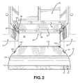
- central cabinet 25, as shown in Figure 2 includes a bottom panel or floor 79 and, in this depicted embodiment, a lower support frame 82, shown to include a rear flange piece 85, opposing side flange pieces 86 and 87, and a front flange piece 88.
- Each of rear, side and front flange pieces 85-88 defines a side portion as exemplified by side portion 89 for side flange piece 86.
- support brackets are initially mounted at spaced locations beneath central cabinet 25, i.e., to the underside of cabinet 25.
- central cabinet 25 i.e., to the underside of cabinet 25.
- a support bracket 94 is shown to include an elongated main body 95 taking the form of a plate having a front end portion 97 and a rear end portion 98 which are longitudinally spaced, as well as an upper edge 99 and a lower edge 100.
- elongated main body 95 In or adjacent each end portion 97, 98, elongated main body 95 is provided with spaced holes 101 and 102 respectively.
- locator tab 108 which includes a locator extension 110 having a terminal end 115. As shown, locator extension 110 extends below and generally parallel to elongated main body 95.
- first and second support tabs or hangers 120 and 121 are generally established by a connection section 130 securing the support tab 120, 121 along lower edge 100 of main body 95, a main section 132, and a cantilevered projection or finger section 134.
- connection section 130 and finger section 134 main body 95 extends for a certain distance spaced from main body 95 such that a slit or recess140 is established, with slit 140 opening toward finger section 134 and terminating at connection section 130. From slit 140, main body 95 leads to finger section 134 through a tapered or ramped section 144.
- both finger section 134 and slit 140 are sized based on the thickness of the material of housing 72 of ventilation hood 70.
- a hole 148 is provided within main section 132.
- second support tab 121 is similarly constructed to first support tab 120 such that a reiterative description will not be made here.
- the various longitudinal dimensions of the various sections of the support tabs 120 and 121 can vary (for instance the main section of support tab 121 is shown to be shorter than the main section of support tab 120), the embodiment depicted illustrates the respective finger sections 134 and slits 140 to have substantially corresponding dimensions.
- support bracket 94 is made of sheet metal which is stamped to create each of main body 95, locator tab 108 and first and second support tabs 120 and 121.
- housing 72 of ventilation hood 70 is also formed of sheet metal and, as best shown in Figure 2 , includes a top panel 153, a sloping section 155 and a front panel 157 created by bending and shaping a piece of sheet metal.
- top panel 153 is formed with a pair of spaced, front slots 160 and 161, as well as a pair of spaced, rear slots 162 and 163.
- each pair or set of front and rear slots 160 and 162, 161 and 163 on each side of top panel 153 partially receives a respective support tab 120, 121 for mounting of ventilation hood 70.
- the outer lateral dimension of lower support frame 82 is standard based on the distance between wall cabinets 22 and 23.
- ventilation hood 70 is dimensioned and manufactured accordingly.
- the depth of cabinet 25 may not be the same as cabinets 22 and 23.
- uniformity in the positioning of support brackets 120 and 121 from rear wall 20 is crucial in addressing mounting alignment issues.
- the first step in connection with the mounting method for ventilation hood 70 is to mount first and second support brackets 94 to lower support frame 82 and at predetermined positions relative to both rear wall 20 and side flange portions 86 and 87.
- support bracket 94 is mounted to side flange portion 86 by placing main body 95 against side portion 89, aligning lower edge 100 so as to be flush with a bottom of side flange portion 86 and abutting terminal end 115 of locator extension 110 with rear wall 20.
- mechanical fasteners such as wood screws (not shown) are inserted into holes 101 and 102 and driven into side flange portion 86.
- This same process is then performed for side flange portion 87 such that two fore-to-aft extending support brackets 94 are mounted at spaced locations beneath cabinet 25 with finger sections 134 of support tabs 120 and 121 projecting forward or away from rear wall 20.
- ventilation hood 70 can be hung from the spaced support brackets 94 by aligning the respective support tabs 120 and 121 on each side of cabinet 25 with a respective pair of front and rear slot 160 and 162, 161 and 163 on each side of top panel 153, inserting each support tab 120, 121 into a respective slot 160-163 and then shifting ventilation hood 70 rearward.
- a portion of top panel 153 will be received with a respective slit 140 as shown in Figure 4 .
- each tapered section 144 ramps and guides the movement, thereby forcing ventilation hood 70 upward during the rearward shifting and assuring that ventilation hood 70 abuts snugly against cabinet 25.
- each locator tab 108 is also accommodated in a respective rear slot 162, 163 as slots 162 and 163 open out the back panel (not separately labeled) of ventilation hood 70.
- each support tab 120, 121 is bent upward against top panel 153 along a respective connection section 130 to assume the position shown in Figure 5 .
- the assembly can be considered complete, with ventilation hood 70 being in an operational position.
- each support bracket 94 would include support tabs 120' and 121' (see Figure 3 ) which are connected to main body 95 along edge 99 at right angles, i.e. perpendicular, to both support tabs 120 and 121 and main body 95. As support tabs 120' and 121' are identically configured to support tabs 120 and 121, the structure thereof will not be repeated.
- support bracket 94 is rotated so that main body 95 is flat against bottom panel 79, support brackets 120 and 121 are arranged flush with outermost portions of the cabinet so as to act as spacers which position main body 95 a requisite distance from an outermost lateral edge of cabinet 25 (i.e., a distance equal to the standard thickness of side flange portion 86 or 87), terminal end 115 again abuts rear wall 20 at a height commensurate with main body 95 and ventilation hood 70 is then hung from support tabs 120' and 121' in a manner directly corresponding to that set forth above.
- support tabs 120' and 121' are not needed if mounting ventilation hood 70 to cabinet 25 with lower support frame 82 and the function of support tabs 120 and 121 when utilizing support bracket 94 with a frameless cabinet could be performed by structure lacking at least finger section 134, slit 140, tapered section 140 and hole 148.
- an outline of the frame to which lower panel 79 is attached can typically be seen so a visual alignment of main body 95 is possible.
- support brackets 94 are structured in the manner illustrated in the figures, it should be apparent that a universal bracket is established in accordance with the invention to enable the mounting of ventilation hood 70 with either type of known cabinetry.
- each configuration provides for the use of support brackets employing distinct aligning (vertically and/or laterally), positioning (fore-to-aft relative to a rear wall) and hanging features which enables a ventilation hood to be mounted in an easy and efficient manner by a single person, without the need for measuring, cutting and installing filler strips as common in the art.
Abstract
Description
- The present invention pertains to the art of cooking and, more particularly, to a system and method for mounting a ventilation hood under cabinetry positioned above a cooking appliance.
- In the art of cooking, numerous types of cooking appliances are known, including both slide-in and drop-in ranges. Basically, both types of ranges are designed to be situated in a space or cut-out provided along a length of a kitchen countertop. In either case, the range includes at least one oven cavity supported below a cooktop. Of course, it is also known to separately mount cooktops, without lower oven cavities, in countertops. In any case, when the cooktop is utilized for cooking operations, a certain degree of smoke, grease or the like can be created. To counter the airborne nature of these byproducts, it is known to mount a ventilation unit above the range. Basically, such known ventilation units include an exhaust fan which functions to draw the smoke and other byproducts away from the cooktop. The byproducts are typically either directed to a vent external of the cooking area or filtered such that the cleansed air is simply expelled back into the cooking area. Such known ventilation units can take the form of a ventilation hood or can be incorporated into an overhead microwave oven mounted above the range. In many situations, the ventilation unit will also incorporate a light to aid in illuminating the cooktop.
- In mounting a ventilation unit incorporated into a microwave oven to the bottom of a cabinet which is centered above and spans the appliance, it is commonplace to bolt the ventilation unit to a bottom cabinet panel. More specifically, a housing of the microwave oven is provided with spaced front and rear mounting holes and a template can be provided which enables an installer to mark drilling locations in the bottom panel of the cabinet, with the intent that the drilled holes will be aligned with pre-formed mounting holes in the unit. Assuming the proper alignment exists, the microwave oven can be held in a position beneath the upper cabinet and bolts inserted through each of the aligned hole sets to secure the microwave oven in place. In the case of a ventilation hood, the housing of the hood is typically used as a template for determining appropriate fastener locations and then filler strips are measured, cut and installed beneath the cabinet to complete lower framing needed to mount the ventilation hood.
- Certain problems are considered to exist in each of these overall mounting arrangements. First of all, at least in the case ventilation units incorporated in microwave ovens, it is common for the template to take the form of a folded paper template which must be unfolded, cut to fit the underside of the upper cabinet and taped or otherwise retained in position to establish the drilling locations. Given that creases and improper cuts can contribute to misalignment issues, it is not uncommon for product manufacturers to recommend that significantly larger holes be drilled than needed to receive the bolts, and washers are provided to accommodate the enlarged holes. In this manner, a degree of tolerance is established to better assure potential alignment of each bolt with a designated hole in the ventilation unit. In the case of ventilation hoods, the measuring, cutting and mounting of filler strips can be quite tedious and time consuming, particularly if a professional installer is not employed. In both types of mounting arrangements, a second significant problem is that, after the holes are drilled and it is time to actually secure the ventilation unit, two people are required, one for holding the ventilation unit in place and the other for inserting and tightening at least a couple of the bolts. Certainly, given the confined space and the need to hold the unit around eyelevel for some time, this operation is less than desirable.
- Although two people may be necessary for mounting a microwave, it is desired in accordance with the present invention to provide a method which enables a single user to readily install a ventilation hood over a cooking appliance through the use of a simplified and efficient installation system.
- The present invention is directed to a system and method for mounting a ventilation hood above a cooking appliance and under a cabinet, such as in a kitchen. In general, the system employs a pair of support brackets mounted to the underside of the cabinet at laterally spaced, left and right positions, with each support bracket including distinct aligning, positioning and hanging structure which enables a single person to readily mount the ventilation hood to the cabinet. More specifically, each support bracket includes a main body from which depend at least one and, more preferably, first and second longitudinally spaced support tabs or hangers, as well as a locator tab. Alignment structure enables the main body to be easily positioned for mounting to the cabinet in a requisite manner, while the locator tab assures that the support bracket is positioned a required distance from a rear wall extending behind the cabinet. Once the support brackets are properly positioned, aligned and mounted, the ventilation hood can be positioned so that the support tab(s) is/are received in one or more slots formed in a top panel of the hood and, upon sliding the ventilation hood rearward, the hood rides upon ramped or tapered surface of each support tab to position the hood against the cabinet while hanging the hood from the support tab(s). Thereafter, the support tab(s) can be bent to retain the ventilation hood in an operational position. If desired, a mechanical fastener can be employed to secure each bent support tab to the ventilation hood.
- In accordance with a further aspect of the invention, the support brackets are configured for use in mounting a ventilation hood beneath a frameless cabinet, i.e., a cabinet having supports above the bottom panel. In this situation, each support bracket is provided with one or more support tabs or hangers which project perpendicular to the main body. The main body is again aligned, either visually or through the use of spacers and positioned from the rear wall by the locator tab. In connection in a universal support bracket arrangement, the support tab(s) employed with mounting the ventilation hood on a cabinet including a lower frame can be used as the lateral spacers. In any case, once the support brackets appropriately mounted, a corresponding hanging and securing operation for the ventilation hood can be readily effected by a single person.
- Additional objects, features and advantages of the invention will become readily apparent from the following detailed description of preferred embodiments of the invention when taken in conjunction with the drawings wherein like reference numerals refer to corresponding parts in the several views.
-
-
Figure 1 is a perspective view illustrating a ventilation hood mounted in accordance with the invention to cabinetry positioned above a range in a kitchen environment; -
Figure 2 is a partial exploded view of a first stage in the mounting of the ventilation hood ofFigure 1 in accordance with the invention; -
Figure 3 is a perspective view of an under cabinet support bracket mounting configuration employed in the invention; -
Figure 4 is a lower perspective view of the ventilation hood ofFigure 1 in an initial mounting stage; and -
Figure 5 is a lower perspective view of the ventilation hood in a final mounting stage. - With initial reference to
Figure 1 , acooking appliance 2 is shown positioned in a cut-out or opening 5 provided in acountertop 8 and between adjacentlower cabinetry upper surface 17 extending to a rearupstanding wall 20. Abovecountertop 8 are shownwall cabinets cooking appliance 2, as well as acentral cabinet 25 arranged above at least a portion ofcooking appliance 2 and betweencabinets - Within the scope of the invention,
cooking appliance 2 can take on various forms, including all fuel type ranges and built-in cooktops. However, in the exemplary embodiment illustrated,cooking appliance 2 is illustrated as a range including a cabinet orshell 30 which supports anoven cavity 33 located behind adoor 35 having ahandle 38 and a window 40. In a manner known in the art,door 35 can be pivoted to accessoven cavity 33. Also, as shown,cooking appliance 2 includes alower drawer 44 for use in storing pans and the like. In addition,cooking appliance 2 includes anupper control panel 51 having a central oven control section 54. Furthermore,control panel 51 is shown provided with a plurality of control knobs, one of which is indicated at 57, for regulating operation of upper cooktop heating elements or burners, such as that indicated at 61. - Particularly with the inclusion of the heating elements or
burners 61, operation ofcooking appliance 2 can produce smoke, grease or other airborne byproducts. To counter the potential detrimental effects of these cooking byproducts, it is desired to mount aventilation hood 70 abovecooking appliance 2, specifically to the underside ofcentral cabinet 25 and betweenside wall cabinets ventilation hood 70, specifically a mounting arrangement which enables a single installer to readily and efficiently secureventilation hood 70 tocentral cabinet 25. - In general, the operation of
ventilation hood 70 is also known in the art. Therefore, apart from particular details set forth hereinafter, it should be recognized that the actual construction ofventilation hood 70 can vary from that depicted. Therefore, althoughventilation hood 70 is shown to include ahousing 72 andcontrol knobs ventilation hood 70, it should also be recognized thatcentral cabinet 25 is also of known construction. That is, although the exact materials and construction can vary,central cabinet 25, as shown inFigure 2 , includes a bottom panel orfloor 79 and, in this depicted embodiment, alower support frame 82, shown to include arear flange piece 85, opposingside flange pieces front flange piece 88. Each of rear, side and front flange pieces 85-88 defines a side portion as exemplified byside portion 89 forside flange piece 86. - In accordance with one aspect of the invention, support brackets are initially mounted at spaced locations beneath
central cabinet 25, i.e., to the underside ofcabinet 25. As the support brackets for the opposing sides ofcabinet 25 are mirror images of each other, a detailed description of one side support bracket will now be made and it is to be understood that corresponding structure exists in connection with the other side bracket. More particularly, for the left side ofcabinet 25 as shown inFigures 2 and3 , asupport bracket 94 is shown to include an elongatedmain body 95 taking the form of a plate having afront end portion 97 and arear end portion 98 which are longitudinally spaced, as well as anupper edge 99 and a lower edge 100. In or adjacent eachend portion main body 95 is provided with spacedholes rear end portion 98 of elongatedmain body 95 is alocator tab 108 which includes alocator extension 110 having aterminal end 115. As shown,locator extension 110 extends below and generally parallel to elongatedmain body 95. - Also depending from elongated
main body 95 at spaced longitudinal positions are first and second support tabs orhangers second support tabs connection section 130 securing thesupport tab main body 95, amain section 132, and a cantilevered projection orfinger section 134. As clearly illustrated inFigure 3 , betweenconnection section 130 andfinger section 134,main body 95 extends for a certain distance spaced frommain body 95 such that a slit or recess140 is established, withslit 140 opening towardfinger section 134 and terminating atconnection section 130. Fromslit 140,main body 95 leads tofinger section 134 through a tapered or rampedsection 144. For reasons which will become more fully evident below, bothfinger section 134 and slit 140 are sized based on the thickness of the material ofhousing 72 ofventilation hood 70. Finally, provided withinmain section 132 is ahole 148. Again,second support tab 121 is similarly constructed tofirst support tab 120 such that a reiterative description will not be made here. However, it should be noted that, although the various longitudinal dimensions of the various sections of thesupport tabs support tab 121 is shown to be shorter than the main section of support tab 120), the embodiment depicted illustrates therespective finger sections 134 andslits 140 to have substantially corresponding dimensions. - In the embodiment shown,
support bracket 94 is made of sheet metal which is stamped to create each ofmain body 95,locator tab 108 and first andsecond support tabs housing 72 ofventilation hood 70 is also formed of sheet metal and, as best shown inFigure 2 , includes atop panel 153, a slopingsection 155 and afront panel 157 created by bending and shaping a piece of sheet metal. For use in mountingventilation hood 70,top panel 153 is formed with a pair of spaced,front slots rear slots rear slots top panel 153 partially receives arespective support tab ventilation hood 70. - In connection with the invention, it is recognized that the outer lateral dimension of
lower support frame 82 is standard based on the distance betweenwall cabinets ventilation hood 70 is dimensioned and manufactured accordingly. However, based on electrical or other issues, the depth ofcabinet 25 may not be the same ascabinets ventilation hood 70, uniformity in the positioning ofsupport brackets rear wall 20 is crucial in addressing mounting alignment issues. With this information in mind, the first step in connection with the mounting method forventilation hood 70 is to mount first andsecond support brackets 94 tolower support frame 82 and at predetermined positions relative to bothrear wall 20 andside flange portions support bracket 94 is mounted toside flange portion 86 by placingmain body 95 againstside portion 89, aligning lower edge 100 so as to be flush with a bottom ofside flange portion 86 and abuttingterminal end 115 oflocator extension 110 withrear wall 20. Once properly positioned in this matter, mechanical fasteners, such as wood screws (not shown), are inserted intoholes side flange portion 86. This same process is then performed forside flange portion 87 such that two fore-to-aft extendingsupport brackets 94 are mounted at spaced locations beneathcabinet 25 withfinger sections 134 ofsupport tabs rear wall 20. - At this stage,
ventilation hood 70 can be hung from the spacedsupport brackets 94 by aligning therespective support tabs cabinet 25 with a respective pair of front andrear slot top panel 153, inserting eachsupport tab ventilation hood 70 rearward. With this rearward shifting, a portion oftop panel 153 will be received with arespective slit 140 as shown inFigure 4 . During this rearward movement, eachtapered section 144 ramps and guides the movement, thereby forcingventilation hood 70 upward during the rearward shifting and assuring thatventilation hood 70 abuts snugly againstcabinet 25. At the same time, a portion of eachlocator tab 108 is also accommodated in a respectiverear slot slots ventilation hood 70. Thereafter, eachsupport tab top panel 153 along arespective connection section 130 to assume the position shown inFigure 5 . At this point, aside from any potential electrical issues, the assembly can be considered complete, withventilation hood 70 being in an operational position. However, it is also proposed in accordance with the invention to provide a further securing feature by enabling one or more mechanical fasteners, such as metal screws (not shown), to extend through hole(s) 148 and intotop panel 153. - In the embodiment described above,
cabinet 25 is provided withlower support frame 82. However, another standard type of cabinet is frameless such that the lowermost exposed portion would correspond tobottom panel 79. To accommodate use of the invention with this type of known cabinet, eachsupport bracket 94 would include support tabs 120' and 121' (seeFigure 3 ) which are connected tomain body 95 alongedge 99 at right angles, i.e. perpendicular, to bothsupport tabs main body 95. As support tabs 120' and 121' are identically configured to supporttabs support bracket 94 is rotated so thatmain body 95 is flat againstbottom panel 79,support brackets side flange portion 86 or 87),terminal end 115 again abutsrear wall 20 at a height commensurate withmain body 95 andventilation hood 70 is then hung from support tabs 120' and 121' in a manner directly corresponding to that set forth above. Certainly, support tabs 120' and 121' are not needed if mountingventilation hood 70 tocabinet 25 withlower support frame 82 and the function ofsupport tabs support bracket 94 with a frameless cabinet could be performed by structure lacking atleast finger section 134, slit 140, taperedsection 140 andhole 148. In addition, even with cabinets lackinglower support frame 82, an outline of the frame to whichlower panel 79 is attached can typically be seen so a visual alignment ofmain body 95 is possible. In any case, whensupport brackets 94 are structured in the manner illustrated in the figures, it should be apparent that a universal bracket is established in accordance with the invention to enable the mounting ofventilation hood 70 with either type of known cabinetry. - Although described with respect to preferred embodiments of the invention, it should be readily apparent that various changes and/or modifications can be made to the invention. For instance, it should be readily apparent that the invention can employ various different fastener assemblies in connection with an overall system and method for mounting a ventilation hood to an underside of a cabinet, including frame-type and frameless cabinets. In addition, although the embodiments described above reference two support tabs on each bracket, it should be recognized that a single, elongate support tab establishing an elongated slit or recess, or more than two support tabs on each bracket, could be employed. In any case, it should be recognized that each configuration provides for the use of support brackets employing distinct aligning (vertically and/or laterally), positioning (fore-to-aft relative to a rear wall) and hanging features which enables a ventilation hood to be mounted in an easy and efficient manner by a single person, without the need for measuring, cutting and installing filler strips as common in the art.
Claims (15)
- A method of mounting a ventilation hood (70) to an underside of a cabinet (25) positioned along a rear wall (20) above a cooking appliance (2) comprising:securing first and second brackets (94) to the underside of the cabinet (25) at spaced positions, with each of the first and second brackets (94) including a locator tab (108) abutting the rear wall (20) and at least one support tab (120, 121) extending below the cabinet (25);inserting each support tab (120,121) into a respective slot (160, 161,162, 163) provided in a top panel (153) of the ventilation hood (70); andshifting the ventilation hood (70) rearward, causing portions of the top panel (153) of the ventilation hood (70) to be received within slits (140) established between the support tabs (120, 121) and main body (95) portions of the first and second support brackets (94), wherein the ventilation hood (70) is hung from the first and second brackets (94).
- The method of claim 1, further comprising: guiding the ventilation hood (70) during rearward shifting along ramped sections (144) formed on the support tabs (120,121).
- The method of claim 2, wherein guiding the ventilation hood (70) includes forcing the ventilation hood (70) upward during rearward shifting such that the ventilation hood (70) abuts the cabinet (25).
- The method of claim 2, wherein inserting the support tabs (120,121) into the slots (160, 161,162, 163) provided in the top panel (153) of the ventilation hood (70) initially includes inserting finger sections (134) of the support tabs (120,121) into the slots (160, 161,162, 163), with the finger sections (134) leading to the ramped sections (144).
- The method of claim 1, wherein at least one of the slots (160, 161,162, 163) provided in the top panel (153) of the ventilation hood (70) extends into a back panel of the ventilation hood (70) such that inserting the supporting tabs (120, 121) into the slots (160, 161,162, 163) and shifting the ventilation hood (70) rearward causes at least the locator tab (108) to extend through the back panel.
- The method of claim 1, further comprising: securing the ventilation hood (70) by bending the support tabs (120,121) against the top panel (153).
- The method of claim 6, further comprising: additionally securing the ventilation hood (70) by mechanically fastening the support tabs (120,121) to the top panel (153).
- The method of claim 6, wherein each of the support tabs (120,121) is connected to one of the first and second brackets (94) through a connection section (130) and bending the support tabs (120,121) constitutes bending along a respective said connection section (130).
- The method of claim 1, wherein inserting the support tabs (120,121) into the slots (160, 161,162, 163) provided in a top panel (153) of the ventilation hood (70) includes inserting multiple, fore-to-aft spaced support tabs (120,121) into multiple slots (160, 161,162, 163) on each lateral side of the ventilation hood (70).
- The method of claim 1, wherein securing the first and second brackets (94) to the underside of the cabinet (25) includes mechanically fastening the first and second brackets (94) to side support flanges of a lower support frame (82) of the cabinet (25) and abutting the locator tab (108) constitutes engaging a terminal end (115) of the locator tab (108) with the rear wall (20) at a position below the lower support frame (82).
- The method of claim 1, wherein securing the first and second brackets (94) to the underside of the cabinet (25) includes mechanically fastening the main body (95) of each of the first and second brackets (94) directly to a bottom panel of the cabinet (25) and abutting the locator tab (108) constitutes engaging a terminal end (115) of the locator tab (108) with the rear wall (20) at a height commensurate with the main body (95).
- The method of claim 11, further comprising: employing additional support tabs (120,121) extending from the first and second brackets (94) as spacers to position the first and second brackets (94) relative to the bottom panel for mechanical fastening purposes.
- A system for mounting a ventilation hood (70) to an underside of a cabinet (25) positioned along a rear wall (20) above a cooking appliance (2) comprising:first and second brackets (94) configured to be mounted to the underside of the cabinet (25) at spaced positions, each of the first and second brackets (94) including a main body (95), a locator tab (108) extending from the main body (95) for abutting the rear wall (20) and at least one support tab (120,121) extending from the main body (95) through a respective connection section (130) and defining, in combination with the main body (95), a slit (140), with the support tabs (120,121) being configured to extend below the cabinet (25) upon mounting the first and second brackets (94); anda ventilation hood (70) including a top panel (153) provided with slots (160, 161,162, 163) for receiving the support tabs (120,121) in order to hang the ventilation hood (70) from the first and second brackets (94) with portions of the top panel (153) being received in the slits (140), wherein the ventilation hood (70) further includes a back panel and the slots (160, 161,162, 163) include fore-to-aft spaced slots (160, 161,162, 163) on each lateral side of the top panel (153), with rear ones of the slots (160, 161,162, 163) extending into the back panel.
- The system of claim 15, wherein the main body (95) of each of the first and second brackets (94) includes holes for receiving mechanical fasteners used to mount the first and second brackets (94) to the underside of the cabinet (25), and wherein the main body (95) of each of said first and second brackets (94) includes two pairs of the support tabs (120,121), with one set of the pairs of the support tabs (120,121) extending perpendicular from the main body (95) and relative to another set of the pairs of support tabs (120,121).
- The system of claim 15, wherein each of the support tabs (120,121) includes a ramped section (144) for guiding the ventilation hood (70) into the slits (140), and wherein each of the support tabs (120,121) further includes a finger section (134) for initially inserting into a respective one of the slots (160, 161,162, 163), said finger section (134) leading to a respective said ramped section (144).
Applications Claiming Priority (1)
| Application Number | Priority Date | Filing Date | Title |
|---|---|---|---|
| US13/966,311 US9523507B2 (en) | 2013-08-14 | 2013-08-14 | Method for mounting undercabinet ventilation hood |
Publications (3)
| Publication Number | Publication Date |
|---|---|
| EP2840323A2 true EP2840323A2 (en) | 2015-02-25 |
| EP2840323A3 EP2840323A3 (en) | 2015-10-14 |
| EP2840323B1 EP2840323B1 (en) | 2017-04-26 |
Family
ID=51265503
Family Applications (1)
| Application Number | Title | Priority Date | Filing Date |
|---|---|---|---|
| EP14179018.8A Active EP2840323B1 (en) | 2013-08-14 | 2014-07-29 | System and method for mounting undercabinet ventilation hood |
Country Status (4)
| Country | Link |
|---|---|
| US (3) | US9523507B2 (en) |
| EP (1) | EP2840323B1 (en) |
| BR (1) | BR102014020002A2 (en) |
| MX (1) | MX366022B (en) |
Cited By (3)
| Publication number | Priority date | Publication date | Assignee | Title |
|---|---|---|---|---|
| FR3045787A1 (en) * | 2015-12-21 | 2017-06-23 | Groupe Brandt | SUCTION HOOD AND ASSOCIATED SIMPLIFIED INSTALLATION METHOD |
| CN108027146A (en) * | 2015-05-19 | 2018-05-11 | 布罗恩-努托恩有限责任公司 | Smoke exhaust ventilator installation system |
| WO2019223403A1 (en) * | 2018-05-24 | 2019-11-28 | 宁波方太厨具有限公司 | Control panel structure of range hood |
Families Citing this family (8)
| Publication number | Priority date | Publication date | Assignee | Title |
|---|---|---|---|---|
| US9897330B2 (en) * | 2013-05-29 | 2018-02-20 | Whirlpool Corporation | System and method for mounting undercabinet ventilation hood |
| US10018365B2 (en) * | 2013-05-29 | 2018-07-10 | Whirlpool Corporation | System and method for mounting undercabinet ventilation hood |
| US10208961B2 (en) | 2015-07-16 | 2019-02-19 | Pennant Moldings, Inc. | One-piece sheet-metal structure formed with clench locked corners |
| US9320357B1 (en) | 2015-09-09 | 2016-04-26 | Jiaxing Tian | System and method for single person mounting of wall-mounted cabinets or shelves |
| US10215422B2 (en) | 2016-01-04 | 2019-02-26 | Haier Us Appliance Solutions, Inc. | Appliance hood mounting system |
| AU2018288433B2 (en) * | 2017-06-20 | 2024-01-25 | Dometic Sweden Ab | Slide out kitchen |
| US11864296B2 (en) | 2020-11-04 | 2024-01-02 | Midea Group Co., Ltd. | Mounting arrangement for over-the-range cooking appliance |
| EP4006433A1 (en) * | 2020-11-30 | 2022-06-01 | Electrolux Appliances Aktiebolag | Extraction device and method for assembling a ventilation system |
Family Cites Families (63)
| Publication number | Priority date | Publication date | Assignee | Title |
|---|---|---|---|---|
| US3125869A (en) | 1964-03-24 | Ventilating apparatus | ||
| US510510A (en) | 1893-12-12 | Alexander asbury johnson | ||
| US1467781A (en) | 1922-05-03 | 1923-09-11 | Hugh G Buchan | Means for securing headed articles in place |
| US2839987A (en) | 1954-03-03 | 1958-06-24 | Emerson Pryne Company | Ventilating hood construction |
| US2887351A (en) | 1957-05-31 | 1959-05-19 | American Air Filter Co | Storage cabinet |
| US2971451A (en) | 1958-06-16 | 1961-02-14 | Progress Mfg Company | Ventilator unit |
| US3098423A (en) * | 1961-02-10 | 1963-07-23 | Anthony J Giannini | Adjustable exhaust hood |
| US3372632A (en) | 1966-06-06 | 1968-03-12 | Home Metal Prod Co | Cabinet mounted hood assembly |
| US3749465A (en) | 1971-03-22 | 1973-07-31 | Amerock Corp | Knock down cabinet and hardware for assembling the same |
| US3768064A (en) | 1971-11-22 | 1973-10-23 | Acme Lane Co Inc | Safety back for cabinets |
| JPS5121694B2 (en) | 1972-03-09 | 1976-07-05 | ||
| US4011803A (en) | 1975-04-10 | 1977-03-15 | Aubrey Manufacturing, Incorporated | Range-hood installation device |
| DE7530601U (en) | 1975-09-27 | 1976-01-29 | Sueddeutsche Metallwerke Gmbh, 6909 Walldorf | BRACKET FOR A WALL CABINET |
| DE2656225C3 (en) | 1976-12-11 | 1981-03-26 | Karl Lautenschläger KG, Möbelbeschlagfabrik, 64354 Reinheim | Packaging for furniture hinges |
| US4775273A (en) | 1981-01-23 | 1988-10-04 | Peter Bauer | Bistable shaft retaining element |
| US4437712A (en) | 1981-07-09 | 1984-03-20 | Wissinger John W | Cabinet system |
| JPS5827512A (en) | 1981-08-11 | 1983-02-18 | シャープ株式会社 | Attachment of kitchen furniture having plural functions |
| US4465256A (en) | 1981-11-24 | 1984-08-14 | Broan Mfg. Co., Inc. | Mounting device for range hoods |
| US4445690A (en) | 1982-02-22 | 1984-05-01 | Cairns Frank D | Game apparatus |
| DE3331836A1 (en) | 1983-09-03 | 1985-03-21 | Alno-Möbelwerke GmbH & Co KG, 7798 Pfullendorf | HANGING FITTING FOR HANGING CABINETS |
| US4614177A (en) | 1984-05-03 | 1986-09-30 | Broan Mfg. Co., Inc. | Multi feature range hood |
| DE3417453A1 (en) | 1984-05-11 | 1985-11-14 | Licentia Patent-Verwaltungs-Gmbh, 6000 Frankfurt | Vapour extractor hood for arrangement above kitchen cookers or the like |
| US4580853A (en) | 1984-09-12 | 1986-04-08 | Toastmaster Inc. | Undercabinet mounting arrangement for cooking appliances |
| JPS6176213U (en) | 1984-10-24 | 1986-05-22 | ||
| JPS61164918U (en) | 1985-03-14 | 1986-10-13 | ||
| CA1266878A (en) | 1985-03-20 | 1990-03-20 | Matsushita Electric Industrial Co., Ltd. | Hanger for kitchen appliances |
| JPS61228228A (en) | 1985-04-03 | 1986-10-11 | Sanyo Electric Co Ltd | Installment for cooking utentil |
| US4630532A (en) | 1985-04-12 | 1986-12-23 | John Zink Company | Coffeemaker |
| US4628185A (en) | 1985-08-05 | 1986-12-09 | Black & Decker, Inc. | Toaster oven and protective hood |
| US4792195A (en) | 1987-08-06 | 1988-12-20 | Kidde Holding, Inc. | Drawer support system |
| JPH02126038A (en) | 1988-11-02 | 1990-05-15 | Mitsubishi Electric Corp | Hood mounting device |
| DE4121524C2 (en) | 1991-06-28 | 1994-07-14 | Deutsche Aerospace Airbus | Screw connection |
| US5333827A (en) | 1992-07-14 | 1994-08-02 | Sony Electronics, Inc. | Mounting assembly for suspending an electrical appliance from an elevated cabinet |
| US5774319A (en) | 1993-10-27 | 1998-06-30 | Square D Company | Energy validation arrangement for a self-powered circuit interrupter |
| IT1278953B1 (en) | 1995-01-12 | 1997-12-02 | Turboair Spa | COOKER HOOD INCLUDING A SUCTION AND / OR FILTRATION GROUP |
| US5887388A (en) | 1997-01-21 | 1999-03-30 | Thulman Eastern Corporation | In-the-room fireplace system |
| FR2766112B1 (en) | 1997-07-17 | 1999-10-15 | Air France | EFFLUENT SENSOR FOR PROFESSIONAL KITCHENS |
| JPH1151436A (en) | 1997-08-06 | 1999-02-26 | Matsushita Seiko Co Ltd | Center hood |
| CA2285492C (en) | 1998-10-08 | 2005-01-04 | Sanyo Electric Co., Ltd. | Cooking appliance with ventilation system comprising cover |
| US6341754B1 (en) | 1999-10-04 | 2002-01-29 | Hp Intellectual Corp. | Small appliance modular hanger system |
| US6444954B1 (en) | 1999-11-10 | 2002-09-03 | Hamilton Beach/Proctor-Silex, Inc. | Toaster ovens |
| TWM247976U (en) | 2003-12-02 | 2004-10-21 | Hon Hai Prec Ind Co Ltd | Electronic device suspending structure assembly |
| KR20050074676A (en) | 2004-01-14 | 2005-07-19 | 삼성전자주식회사 | Wall mounted type microwave oven |
| US20050246989A1 (en) | 2004-04-02 | 2005-11-10 | Pringle David L | Backsplash assembly and method |
| DE102005013458A1 (en) | 2004-04-20 | 2005-11-10 | ACCULUBE Manufacturing GmbH - Schmiermittel und -geräte - | Apparatus and method for providing a fine oil mist |
| DE102004036416B4 (en) | 2004-07-27 | 2007-09-27 | Miele & Cie. Kg | Hood |
| US20060042622A1 (en) | 2004-08-26 | 2006-03-02 | Searer Floyd A | Wall-mounted range hood |
| DE102004042230B4 (en) * | 2004-09-01 | 2009-11-12 | Miele & Cie. Kg | Mounting system for a wall-mounted extractor hood |
| JP4480558B2 (en) | 2004-12-01 | 2010-06-16 | 富士工業株式会社 | Range food |
| JP2006234361A (en) | 2005-02-28 | 2006-09-07 | Sun Wave Ind Co Ltd | Mounting bracket for range hood panel, and mounting structure of range hood panel by using the same |
| CN1888577B (en) | 2005-06-29 | 2010-09-08 | 广东松下环境系统有限公司 | Shallow type kitchen fumes exhauster mounting structure |
| US20070256681A1 (en) | 2006-05-03 | 2007-11-08 | Chi-Hsiung Chiang | Smoke exhauster mounting structure |
| WO2008016739A2 (en) | 2006-08-02 | 2008-02-07 | Unified Brands, Inc. | Kitchen ventilation hood apparatus |
| DE102006060498A1 (en) | 2006-12-19 | 2008-06-26 | Miele & Cie. Kg | Extractor hood is made up of two sheet-metal sections with edge sections which are bent over and are locked together by hooked lug on one edge which fits into slot in edge of other |
| US20080184538A1 (en) | 2007-02-01 | 2008-08-07 | Shellnutt Timothy D | Zip tie anchor |
| US20080302352A1 (en) | 2007-06-05 | 2008-12-11 | Pearce Richard A | Exhaust Hood and Method of Mounting Same |
| US20090103999A1 (en) | 2007-10-23 | 2009-04-23 | Dominick Joseph Fucito | Toggle bolt assembly |
| US7780128B2 (en) | 2008-01-21 | 2010-08-24 | Walsberg Martin C | Leveling system and method |
| US8066000B2 (en) | 2009-02-17 | 2011-11-29 | John Tsakiris | Extendable hood for microwave oven positioned over the range or cook top |
| DK177442B1 (en) | 2009-03-19 | 2013-05-27 | Tvilum Aps | Brackets for fixing and supporting a cabinet on a wall as well as methods for fixing a cabinet on the wall |
| DE102011051104B3 (en) | 2011-06-16 | 2012-11-22 | Miele & Cie. Kg | Fume extractor hood used in cooking area, has lamp holder equipped with dome-shaped frame formed such that angle of housing is adjustable after removal of lamp |
| CN102878598B (en) | 2011-07-13 | 2016-05-11 | 博西华电器(江苏)有限公司 | Smoke exhaust ventilator |
| DE202012008040U1 (en) | 2012-08-22 | 2012-09-24 | Exklusiv-Hauben Gutmann Gmbh | Hood |
-
2013
- 2013-08-14 US US13/966,311 patent/US9523507B2/en active Active
-
2014
- 2014-06-30 MX MX2014008142A patent/MX366022B/en active IP Right Grant
- 2014-07-29 EP EP14179018.8A patent/EP2840323B1/en active Active
- 2014-08-12 BR BR102014020002A patent/BR102014020002A2/en not_active IP Right Cessation
-
2016
- 2016-11-11 US US15/349,658 patent/US10317093B2/en active Active
-
2019
- 2019-04-10 US US16/379,897 patent/US10948200B2/en active Active
Non-Patent Citations (1)
| Title |
|---|
| None |
Cited By (3)
| Publication number | Priority date | Publication date | Assignee | Title |
|---|---|---|---|---|
| CN108027146A (en) * | 2015-05-19 | 2018-05-11 | 布罗恩-努托恩有限责任公司 | Smoke exhaust ventilator installation system |
| FR3045787A1 (en) * | 2015-12-21 | 2017-06-23 | Groupe Brandt | SUCTION HOOD AND ASSOCIATED SIMPLIFIED INSTALLATION METHOD |
| WO2019223403A1 (en) * | 2018-05-24 | 2019-11-28 | 宁波方太厨具有限公司 | Control panel structure of range hood |
Also Published As
| Publication number | Publication date |
|---|---|
| MX366022B (en) | 2019-06-24 |
| MX2014008142A (en) | 2015-11-16 |
| EP2840323B1 (en) | 2017-04-26 |
| BR102014020002A2 (en) | 2016-02-23 |
| US20170059180A1 (en) | 2017-03-02 |
| US10317093B2 (en) | 2019-06-11 |
| US10948200B2 (en) | 2021-03-16 |
| US20150047198A1 (en) | 2015-02-19 |
| US20190234621A1 (en) | 2019-08-01 |
| US9523507B2 (en) | 2016-12-20 |
| EP2840323A3 (en) | 2015-10-14 |
Similar Documents
| Publication | Publication Date | Title |
|---|---|---|
| US10948200B2 (en) | System for mounting undercabinet ventilation hood | |
| US9897331B2 (en) | System and method for mounting undercabinet ventilation hood | |
| US10240801B2 (en) | System and method for mounting undercabinet ventilation hood | |
| JPS6333047B2 (en) | ||
| CA2779914C (en) | Exhaust baffle for kitchen appliance | |
| US9447978B2 (en) | Range with suspended cooktop | |
| US20140263276A1 (en) | Spring clip attachment for a surface cooking module of a household cooking appliance | |
| US11767986B2 (en) | Systems for mounting kitchen extractor hoods and methods for executing the mounting | |
| US7624730B2 (en) | Adjustable quick install/remove stove guard | |
| US8941038B2 (en) | Support assembly for supporting a household appliance in a free-standing vertical relation with another household appliance | |
| GB2513992A (en) | Method of installing domestic appliances to be one above the other | |
| KR20130011488A (en) | Electric oven | |
| US20220404031A1 (en) | Mounting bracket for over-the-range cooking appliance | |
| US20220400850A1 (en) | Mounting bracket for over-the-range cooking appliance with drill guide | |
| US20220287459A1 (en) | Drawer glide for oven bottom drawer | |
| US9057525B2 (en) | Home appliance with unitary bake element retainer | |
| JP6862301B2 (en) | Range hood and its installation method | |
| JP2006234361A (en) | Mounting bracket for range hood panel, and mounting structure of range hood panel by using the same | |
| US11578874B2 (en) | Cooking appliance with control housing spill control support | |
| US20240133561A1 (en) | Built-in range for recreational vehicles | |
| US11864296B2 (en) | Mounting arrangement for over-the-range cooking appliance | |
| US20230400194A1 (en) | Wall-mounting installation kit for a kitchen hood and method for assembling a hood from the kit | |
| CN113719865A (en) | Hanging assembly and cooking utensil | |
| JPH0275829A (en) | Heating cooker |
Legal Events
| Date | Code | Title | Description |
|---|---|---|---|
| PUAI | Public reference made under article 153(3) epc to a published international application that has entered the european phase |
Free format text: ORIGINAL CODE: 0009012 |
|
| 17P | Request for examination filed |
Effective date: 20140729 |
|
| AK | Designated contracting states |
Kind code of ref document: A2 Designated state(s): AL AT BE BG CH CY CZ DE DK EE ES FI FR GB GR HR HU IE IS IT LI LT LU LV MC MK MT NL NO PL PT RO RS SE SI SK SM TR |
|
| AX | Request for extension of the european patent |
Extension state: BA ME |
|
| PUAL | Search report despatched |
Free format text: ORIGINAL CODE: 0009013 |
|
| AK | Designated contracting states |
Kind code of ref document: A3 Designated state(s): AL AT BE BG CH CY CZ DE DK EE ES FI FR GB GR HR HU IE IS IT LI LT LU LV MC MK MT NL NO PL PT RO RS SE SI SK SM TR |
|
| AX | Request for extension of the european patent |
Extension state: BA ME |
|
| RIC1 | Information provided on ipc code assigned before grant |
Ipc: F24C 15/20 20060101AFI20150908BHEP |
|
| R17P | Request for examination filed (corrected) |
Effective date: 20160414 |
|
| RBV | Designated contracting states (corrected) |
Designated state(s): AL AT BE BG CH CY CZ DE DK EE ES FI FR GB GR HR HU IE IS IT LI LT LU LV MC MK MT NL NO PL PT RO RS SE SI SK SM TR |
|
| REG | Reference to a national code |
Ref country code: DE Ref legal event code: R079 Ref document number: 602014008962 Country of ref document: DE Free format text: PREVIOUS MAIN CLASS: F24C0015200000 Ipc: F24F0013020000 |
|
| RIC1 | Information provided on ipc code assigned before grant |
Ipc: F24F 13/02 20060101AFI20161216BHEP Ipc: F24C 15/20 20060101ALI20161216BHEP |
|
| GRAP | Despatch of communication of intention to grant a patent |
Free format text: ORIGINAL CODE: EPIDOSNIGR1 |
|
| INTG | Intention to grant announced |
Effective date: 20170210 |
|
| GRAS | Grant fee paid |
Free format text: ORIGINAL CODE: EPIDOSNIGR3 |
|
| GRAA | (expected) grant |
Free format text: ORIGINAL CODE: 0009210 |
|
| AK | Designated contracting states |
Kind code of ref document: B1 Designated state(s): AL AT BE BG CH CY CZ DE DK EE ES FI FR GB GR HR HU IE IS IT LI LT LU LV MC MK MT NL NO PL PT RO RS SE SI SK SM TR |
|
| REG | Reference to a national code |
Ref country code: GB Ref legal event code: FG4D |
|
| REG | Reference to a national code |
Ref country code: CH Ref legal event code: EP |
|
| REG | Reference to a national code |
Ref country code: AT Ref legal event code: REF Ref document number: 888236 Country of ref document: AT Kind code of ref document: T Effective date: 20170515 |
|
| REG | Reference to a national code |
Ref country code: IE Ref legal event code: FG4D |
|
| REG | Reference to a national code |
Ref country code: DE Ref legal event code: R096 Ref document number: 602014008962 Country of ref document: DE |
|
| REG | Reference to a national code |
Ref country code: FR Ref legal event code: PLFP Year of fee payment: 4 |
|
| REG | Reference to a national code |
Ref country code: NL Ref legal event code: MP Effective date: 20170426 |
|
| REG | Reference to a national code |
Ref country code: LT Ref legal event code: MG4D |
|
| REG | Reference to a national code |
Ref country code: AT Ref legal event code: MK05 Ref document number: 888236 Country of ref document: AT Kind code of ref document: T Effective date: 20170426 |
|
| PG25 | Lapsed in a contracting state [announced via postgrant information from national office to epo] |
Ref country code: NL Free format text: LAPSE BECAUSE OF FAILURE TO SUBMIT A TRANSLATION OF THE DESCRIPTION OR TO PAY THE FEE WITHIN THE PRESCRIBED TIME-LIMIT Effective date: 20170426 |
|
| PG25 | Lapsed in a contracting state [announced via postgrant information from national office to epo] |
Ref country code: HR Free format text: LAPSE BECAUSE OF FAILURE TO SUBMIT A TRANSLATION OF THE DESCRIPTION OR TO PAY THE FEE WITHIN THE PRESCRIBED TIME-LIMIT Effective date: 20170426 Ref country code: NO Free format text: LAPSE BECAUSE OF FAILURE TO SUBMIT A TRANSLATION OF THE DESCRIPTION OR TO PAY THE FEE WITHIN THE PRESCRIBED TIME-LIMIT Effective date: 20170726 Ref country code: AT Free format text: LAPSE BECAUSE OF FAILURE TO SUBMIT A TRANSLATION OF THE DESCRIPTION OR TO PAY THE FEE WITHIN THE PRESCRIBED TIME-LIMIT Effective date: 20170426 Ref country code: LT Free format text: LAPSE BECAUSE OF FAILURE TO SUBMIT A TRANSLATION OF THE DESCRIPTION OR TO PAY THE FEE WITHIN THE PRESCRIBED TIME-LIMIT Effective date: 20170426 Ref country code: ES Free format text: LAPSE BECAUSE OF FAILURE TO SUBMIT A TRANSLATION OF THE DESCRIPTION OR TO PAY THE FEE WITHIN THE PRESCRIBED TIME-LIMIT Effective date: 20170426 Ref country code: GR Free format text: LAPSE BECAUSE OF FAILURE TO SUBMIT A TRANSLATION OF THE DESCRIPTION OR TO PAY THE FEE WITHIN THE PRESCRIBED TIME-LIMIT Effective date: 20170727 Ref country code: FI Free format text: LAPSE BECAUSE OF FAILURE TO SUBMIT A TRANSLATION OF THE DESCRIPTION OR TO PAY THE FEE WITHIN THE PRESCRIBED TIME-LIMIT Effective date: 20170426 |
|
| PG25 | Lapsed in a contracting state [announced via postgrant information from national office to epo] |
Ref country code: LV Free format text: LAPSE BECAUSE OF FAILURE TO SUBMIT A TRANSLATION OF THE DESCRIPTION OR TO PAY THE FEE WITHIN THE PRESCRIBED TIME-LIMIT Effective date: 20170426 Ref country code: RS Free format text: LAPSE BECAUSE OF FAILURE TO SUBMIT A TRANSLATION OF THE DESCRIPTION OR TO PAY THE FEE WITHIN THE PRESCRIBED TIME-LIMIT Effective date: 20170426 Ref country code: IS Free format text: LAPSE BECAUSE OF FAILURE TO SUBMIT A TRANSLATION OF THE DESCRIPTION OR TO PAY THE FEE WITHIN THE PRESCRIBED TIME-LIMIT Effective date: 20170826 Ref country code: BG Free format text: LAPSE BECAUSE OF FAILURE TO SUBMIT A TRANSLATION OF THE DESCRIPTION OR TO PAY THE FEE WITHIN THE PRESCRIBED TIME-LIMIT Effective date: 20170726 Ref country code: PL Free format text: LAPSE BECAUSE OF FAILURE TO SUBMIT A TRANSLATION OF THE DESCRIPTION OR TO PAY THE FEE WITHIN THE PRESCRIBED TIME-LIMIT Effective date: 20170426 Ref country code: SE Free format text: LAPSE BECAUSE OF FAILURE TO SUBMIT A TRANSLATION OF THE DESCRIPTION OR TO PAY THE FEE WITHIN THE PRESCRIBED TIME-LIMIT Effective date: 20170426 |
|
| REG | Reference to a national code |
Ref country code: DE Ref legal event code: R097 Ref document number: 602014008962 Country of ref document: DE |
|
| PG25 | Lapsed in a contracting state [announced via postgrant information from national office to epo] |
Ref country code: EE Free format text: LAPSE BECAUSE OF FAILURE TO SUBMIT A TRANSLATION OF THE DESCRIPTION OR TO PAY THE FEE WITHIN THE PRESCRIBED TIME-LIMIT Effective date: 20170426 Ref country code: SK Free format text: LAPSE BECAUSE OF FAILURE TO SUBMIT A TRANSLATION OF THE DESCRIPTION OR TO PAY THE FEE WITHIN THE PRESCRIBED TIME-LIMIT Effective date: 20170426 Ref country code: RO Free format text: LAPSE BECAUSE OF FAILURE TO SUBMIT A TRANSLATION OF THE DESCRIPTION OR TO PAY THE FEE WITHIN THE PRESCRIBED TIME-LIMIT Effective date: 20170426 Ref country code: CZ Free format text: LAPSE BECAUSE OF FAILURE TO SUBMIT A TRANSLATION OF THE DESCRIPTION OR TO PAY THE FEE WITHIN THE PRESCRIBED TIME-LIMIT Effective date: 20170426 Ref country code: DK Free format text: LAPSE BECAUSE OF FAILURE TO SUBMIT A TRANSLATION OF THE DESCRIPTION OR TO PAY THE FEE WITHIN THE PRESCRIBED TIME-LIMIT Effective date: 20170426 |
|
| PG25 | Lapsed in a contracting state [announced via postgrant information from national office to epo] |
Ref country code: SM Free format text: LAPSE BECAUSE OF FAILURE TO SUBMIT A TRANSLATION OF THE DESCRIPTION OR TO PAY THE FEE WITHIN THE PRESCRIBED TIME-LIMIT Effective date: 20170426 |
|
| REG | Reference to a national code |
Ref country code: CH Ref legal event code: PL |
|
| PLBE | No opposition filed within time limit |
Free format text: ORIGINAL CODE: 0009261 |
|
| STAA | Information on the status of an ep patent application or granted ep patent |
Free format text: STATUS: NO OPPOSITION FILED WITHIN TIME LIMIT |
|
| 26N | No opposition filed |
Effective date: 20180129 |
|
| PG25 | Lapsed in a contracting state [announced via postgrant information from national office to epo] |
Ref country code: CH Free format text: LAPSE BECAUSE OF NON-PAYMENT OF DUE FEES Effective date: 20170731 Ref country code: LI Free format text: LAPSE BECAUSE OF NON-PAYMENT OF DUE FEES Effective date: 20170731 |
|
| REG | Reference to a national code |
Ref country code: IE Ref legal event code: MM4A |
|
| PG25 | Lapsed in a contracting state [announced via postgrant information from national office to epo] |
Ref country code: SI Free format text: LAPSE BECAUSE OF FAILURE TO SUBMIT A TRANSLATION OF THE DESCRIPTION OR TO PAY THE FEE WITHIN THE PRESCRIBED TIME-LIMIT Effective date: 20170426 |
|
| REG | Reference to a national code |
Ref country code: FR Ref legal event code: PLFP Year of fee payment: 5 |
|
| REG | Reference to a national code |
Ref country code: BE Ref legal event code: MM Effective date: 20170731 |
|
| PG25 | Lapsed in a contracting state [announced via postgrant information from national office to epo] |
Ref country code: LU Free format text: LAPSE BECAUSE OF NON-PAYMENT OF DUE FEES Effective date: 20170729 |
|
| PG25 | Lapsed in a contracting state [announced via postgrant information from national office to epo] |
Ref country code: IE Free format text: LAPSE BECAUSE OF NON-PAYMENT OF DUE FEES Effective date: 20170729 |
|
| PG25 | Lapsed in a contracting state [announced via postgrant information from national office to epo] |
Ref country code: BE Free format text: LAPSE BECAUSE OF NON-PAYMENT OF DUE FEES Effective date: 20170731 |
|
| PG25 | Lapsed in a contracting state [announced via postgrant information from national office to epo] |
Ref country code: MT Free format text: LAPSE BECAUSE OF NON-PAYMENT OF DUE FEES Effective date: 20170729 |
|
| PG25 | Lapsed in a contracting state [announced via postgrant information from national office to epo] |
Ref country code: MC Free format text: LAPSE BECAUSE OF FAILURE TO SUBMIT A TRANSLATION OF THE DESCRIPTION OR TO PAY THE FEE WITHIN THE PRESCRIBED TIME-LIMIT Effective date: 20170426 Ref country code: HU Free format text: LAPSE BECAUSE OF FAILURE TO SUBMIT A TRANSLATION OF THE DESCRIPTION OR TO PAY THE FEE WITHIN THE PRESCRIBED TIME-LIMIT; INVALID AB INITIO Effective date: 20140729 |
|
| PG25 | Lapsed in a contracting state [announced via postgrant information from national office to epo] |
Ref country code: CY Free format text: LAPSE BECAUSE OF FAILURE TO SUBMIT A TRANSLATION OF THE DESCRIPTION OR TO PAY THE FEE WITHIN THE PRESCRIBED TIME-LIMIT Effective date: 20170426 |
|
| PG25 | Lapsed in a contracting state [announced via postgrant information from national office to epo] |
Ref country code: MK Free format text: LAPSE BECAUSE OF FAILURE TO SUBMIT A TRANSLATION OF THE DESCRIPTION OR TO PAY THE FEE WITHIN THE PRESCRIBED TIME-LIMIT Effective date: 20170426 |
|
| PG25 | Lapsed in a contracting state [announced via postgrant information from national office to epo] |
Ref country code: TR Free format text: LAPSE BECAUSE OF FAILURE TO SUBMIT A TRANSLATION OF THE DESCRIPTION OR TO PAY THE FEE WITHIN THE PRESCRIBED TIME-LIMIT Effective date: 20170426 |
|
| PG25 | Lapsed in a contracting state [announced via postgrant information from national office to epo] |
Ref country code: PT Free format text: LAPSE BECAUSE OF FAILURE TO SUBMIT A TRANSLATION OF THE DESCRIPTION OR TO PAY THE FEE WITHIN THE PRESCRIBED TIME-LIMIT Effective date: 20170426 |
|
| PG25 | Lapsed in a contracting state [announced via postgrant information from national office to epo] |
Ref country code: AL Free format text: LAPSE BECAUSE OF FAILURE TO SUBMIT A TRANSLATION OF THE DESCRIPTION OR TO PAY THE FEE WITHIN THE PRESCRIBED TIME-LIMIT Effective date: 20170426 |
|
| P01 | Opt-out of the competence of the unified patent court (upc) registered |
Effective date: 20230522 |
|
| PGFP | Annual fee paid to national office [announced via postgrant information from national office to epo] |
Ref country code: IT Payment date: 20230721 Year of fee payment: 10 Ref country code: GB Payment date: 20230725 Year of fee payment: 10 |
|
| PGFP | Annual fee paid to national office [announced via postgrant information from national office to epo] |
Ref country code: FR Payment date: 20230725 Year of fee payment: 10 Ref country code: DE Payment date: 20230726 Year of fee payment: 10 |