EP2840308A1 - Lamp system - Google Patents
Lamp system Download PDFInfo
- Publication number
- EP2840308A1 EP2840308A1 EP13839866.4A EP13839866A EP2840308A1 EP 2840308 A1 EP2840308 A1 EP 2840308A1 EP 13839866 A EP13839866 A EP 13839866A EP 2840308 A1 EP2840308 A1 EP 2840308A1
- Authority
- EP
- European Patent Office
- Prior art keywords
- lamp
- pair
- straight tube
- pins
- erroneous mounting
- Prior art date
- Legal status (The legal status is an assumption and is not a legal conclusion. Google has not performed a legal analysis and makes no representation as to the accuracy of the status listed.)
- Withdrawn
Links
Images


Classifications
-
- H—ELECTRICITY
- H01—ELECTRIC ELEMENTS
- H01R—ELECTRICALLY-CONDUCTIVE CONNECTIONS; STRUCTURAL ASSOCIATIONS OF A PLURALITY OF MUTUALLY-INSULATED ELECTRICAL CONNECTING ELEMENTS; COUPLING DEVICES; CURRENT COLLECTORS
- H01R13/00—Details of coupling devices of the kinds covered by groups H01R12/70 or H01R24/00 - H01R33/00
- H01R13/64—Means for preventing incorrect coupling
- H01R13/641—Means for preventing incorrect coupling by indicating incorrect coupling; by indicating correct or full engagement
-
- F—MECHANICAL ENGINEERING; LIGHTING; HEATING; WEAPONS; BLASTING
- F21—LIGHTING
- F21K—NON-ELECTRIC LIGHT SOURCES USING LUMINESCENCE; LIGHT SOURCES USING ELECTROCHEMILUMINESCENCE; LIGHT SOURCES USING CHARGES OF COMBUSTIBLE MATERIAL; LIGHT SOURCES USING SEMICONDUCTOR DEVICES AS LIGHT-GENERATING ELEMENTS; LIGHT SOURCES NOT OTHERWISE PROVIDED FOR
- F21K9/00—Light sources using semiconductor devices as light-generating elements, e.g. using light-emitting diodes [LED] or lasers
- F21K9/20—Light sources comprising attachment means
- F21K9/27—Retrofit light sources for lighting devices with two fittings for each light source, e.g. for substitution of fluorescent tubes
- F21K9/272—Details of end parts, i.e. the parts that connect the light source to a fitting; Arrangement of components within end parts
-
- H—ELECTRICITY
- H01—ELECTRIC ELEMENTS
- H01R—ELECTRICALLY-CONDUCTIVE CONNECTIONS; STRUCTURAL ASSOCIATIONS OF A PLURALITY OF MUTUALLY-INSULATED ELECTRICAL CONNECTING ELEMENTS; COUPLING DEVICES; CURRENT COLLECTORS
- H01R33/00—Coupling devices specially adapted for supporting apparatus and having one part acting as a holder providing support and electrical connection via a counterpart which is structurally associated with the apparatus, e.g. lamp holders; Separate parts thereof
- H01R33/05—Two-pole devices
- H01R33/06—Two-pole devices with two current-carrying pins, blades or analogous contacts, having their axes parallel to each other
- H01R33/08—Two-pole devices with two current-carrying pins, blades or analogous contacts, having their axes parallel to each other for supporting tubular fluorescent lamp
- H01R33/0836—Two-pole devices with two current-carrying pins, blades or analogous contacts, having their axes parallel to each other for supporting tubular fluorescent lamp characterised by the lamp holding means
- H01R33/0854—Two-pole devices with two current-carrying pins, blades or analogous contacts, having their axes parallel to each other for supporting tubular fluorescent lamp characterised by the lamp holding means with lamp rotating means
-
- F—MECHANICAL ENGINEERING; LIGHTING; HEATING; WEAPONS; BLASTING
- F21—LIGHTING
- F21V—FUNCTIONAL FEATURES OR DETAILS OF LIGHTING DEVICES OR SYSTEMS THEREOF; STRUCTURAL COMBINATIONS OF LIGHTING DEVICES WITH OTHER ARTICLES, NOT OTHERWISE PROVIDED FOR
- F21V17/00—Fastening of component parts of lighting devices, e.g. shades, globes, refractors, reflectors, filters, screens, grids or protective cages
- F21V17/005—Fastening of component parts of lighting devices, e.g. shades, globes, refractors, reflectors, filters, screens, grids or protective cages with keying means, i.e. for enabling the assembling of component parts in distinctive positions, e.g. for preventing wrong mounting
-
- F—MECHANICAL ENGINEERING; LIGHTING; HEATING; WEAPONS; BLASTING
- F21—LIGHTING
- F21V—FUNCTIONAL FEATURES OR DETAILS OF LIGHTING DEVICES OR SYSTEMS THEREOF; STRUCTURAL COMBINATIONS OF LIGHTING DEVICES WITH OTHER ARTICLES, NOT OTHERWISE PROVIDED FOR
- F21V19/00—Fastening of light sources or lamp holders
- F21V19/0075—Fastening of light sources or lamp holders of tubular light sources, e.g. ring-shaped fluorescent light sources
- F21V19/008—Fastening of light sources or lamp holders of tubular light sources, e.g. ring-shaped fluorescent light sources of straight tubular light sources, e.g. straight fluorescent tubes, soffit lamps
Definitions
- the present invention relates to a lamp system using a straight tube lamp and a socket.
- a straight tube lamp having electrical characteristics different from a straight tube lamp conforming to JEL801 When it is intended to provide a straight tube lamp having electrical characteristics different from a straight tube lamp conforming to JEL801, if a lamp base conforming to JEL801 is used, a straight tube lamp having different electrical characteristics may be erroneously mounted on a socket conforming to JEL801, thereby causing a problem of mismatch of electrical characteristics in instruments using the straight tube lamp and the socket.
- An object of the present invention is to provide a lamp system that includes a straight tube lamp which can be prevented from being erroneously mounted on an incompatible socket, and a socket on which the straight tube lamp can be mounted.
- a lamp system includes a straight tube lamp and a socket.
- the straight tube lamp has a straight tube-shaped cover which accommodates a semiconductor light-emitting element, and at least a portion of which is translucent, and a lamp base which is arranged at both ends of the cover.
- a pair of lamp pins whose distal ends respectively project outward are disposed to project and an erroneous mounting preventing projection is disposed to project.
- the socket has a socket main body whose outer surface has an insertion slot into which the pair of lamp pins are inserted, and whose front surface side has an opening which communicates with the insertion slot and allows the pair of inserted lamp pins to rotate therein, a rotor which is arranged in the opening of the socket main body, which has a groove into which the pair of lamp pins are inserted, and which rotates with the pair of inserted lamp pins, and a pair of terminals to which the pair of rotated lamp pins are connected.
- the socket has a recess into which the erroneous mounting preventing projection is inserted and rotatably moved in response to insertion and rotation of the pair of lamp pins.
- Fig. 5 illustrates a perspective view of a lighting fixture 11 of a lamp system (LED lamp system) 10.
- the lighting fixture 11 is a built-in type lighting fixture for two lamps.
- the lamp system 10 includes an elongated fixture main body 12, a straight tube lamp 13 arranged inside the fixture main body 12, and sockets 14 and 15 which are arranged to oppose each other at both ends of the fixture main body 12 and on which both ends of the straight tube lamp 13 are mounted.
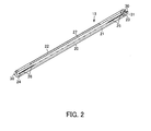
- the straight tube lamp 13 includes a cylindrical translucent cover 20 serving as a cover which is translucent in at least a portion, a light-emitting module 21 and a power supply circuit 22 which are accommodated inside the translucent cover 20, and lamp bases 23 and 24 which are respectively arranged in both end portions of the translucent cover 20.
- the light-emitting module 21 includes multiple semiconductor light-emitting elements 26 such as LED elements and EL elements, and a substrate 27 on which the multiple semiconductor light-emitting elements 26 are mounted. If the multiple semiconductor light-emitting elements 26 are LED elements, a surface mounting-type surface mount device (SMD) package is mounted on the substrate 27, or a chip on board (COB) module in which multiple LED elements are mounted on the substrate 27 is used.
- LED surface mounting-type surface mount device
- COB chip on board
- the power supply circuit 22 supplies DC power, for example, to the light-emitting module 21 by inputting AC power from the lamp base 23 on one end side and converting the AC power into the DC power for turning on the semiconductor light-emitting elements 26.
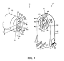
- the lamp bases 23 and 24 at both ends have a shape and structures which are the same as each other. As illustrated in Fig. 1 , a projecting portion 29 projecting along a radial direction through a tube axis of the straight tube lamp 13 is formed on an end surface of the lamp bases 23 and 24 (in Fig. 1 , only the lamp base 23 is illustrated, but the lamp base 24 also has the same shape) at both ends. A pair of lamp pins 30 project from the projecting portion 29 around the tube axis .
- the pair of lamp pins 30 are formed of a flat metal plate having a rectangular shape in a cross section, and are formed to be bent in an L-shape in which leg portions 30a project along a longitudinal direction of the straight tube lamp 13 and bent portions 30b project outward from distal ends of the leg portions 30a so as to be respectively away from the other leg portion 30a.
- the lamp bases 23 and 24 including the pair of lamp pins 30 conform to a "straight tube LED lamp system with an L-shaped lamp base" in Standard JEL801 of the Japan Electric Lamp Manufacturers Association, and are not compatible with a G13-type lamp base, for example.
- An erroneous mounting preventing projection 31 not specified by JEL801 is disposed to project on the end surface of the lamp bases 23 and 24 between the pair of lamp pins 30.
- the erroneous mounting preventing projection 31 is formed into a long rectangular shape along a direction in which the pair of lamp pins 30 oppose each other.
- a dimension L in the longitudinal direction of the erroneous mounting preventing projection 31 is longer than a width dimension W1 of the lamp pins 30, and a width dimension W2 is wider than the width dimension W1 of the lamp pins 30, or is equal to or smaller than the width dimension W1.
- a projecting dimension H of the erroneous mounting preventing projection 31 from the end surface (projecting portion 29) of the lamp bases 23 and 24 will be described in relation to the description of the sockets 14 and 15.
- the straight tube lamp 13 is disposed so that the pair of lamp pins 30 of the lamp bases 23 and 24 at both ends are disposed to project parallel to each other, and that a surface parallel to a direction in which the pair of lamp pins 30 are arrayed side by side is parallel to the substrate 27 of the light-emitting module 21.
- the sockets 14 and 15 (in Figs. 1 and 3 , only the socket 14 is illustrated, but the socket 15 also has the same shape) employ a rotation mounting method in which the straight tube lamp 13 is mounted by being rotated around the tube axis of the straight tube lamp 13 at an angle of 90 degrees after the pair of lamp pins 30 of the straight tube lamp 13 are inserted from the outer surface of the sockets 14 and 15.
- the sockets 14 and 15 include a socket main body 41, a rotor 42 and a pair of terminals 43 which are arranged inside the socket main body 41.
- a side attached to the fixture main body 12 is referred to as a proximal end, and the opposite side is referred to as a distal end.
- a surface opposing the end surface of the straight tube lamp 13 during the mounting is referred to as a lamp base receiving surface 44 which is a front surface, the opposite surface is referred to as a rear surface, and a surface between the front surface and the rear surface is referred to as a side surface.
- the socket main body 41 is made of a synthetic resin having insulating properties, and includes a case 46 whose rear surface is open and a cover 47 which is attached to the rear surface of the case 46.
- An attachment portion 48 attached to the fixture main body 12 is disposed at the proximal end of the case 46.
- An insertion slot 49 into which the pair of lamp pins 30 of the straight tube lamp 13 can be inserted is formed on a distal end surface of the case 46.
- a circular opening 50 with which the insertion slot 49 is adapted to communicate and in which the leg portions 30a of the pair of lamp pins 30 inserted through the insertion slot 49 can be rotated is formed on the lamp base receiving surface 44 which is the front surface of the case 46.
- a pair of terminal holding portions for holding the pair of terminals 43 are formed inside the case 46.
- An electric wire insertion hole is formed on a proximal end surface of the case 46.
- a wall portion 51 is formed to vertically project from the front surface side toward the rear surface side, at an edge portion of the opening 50 which is the opposite side to the insertion slot 49 at the distal end and opposes the insertion slot 49.
- the wall portion 51 is configured so that the bent portion 30b of one lamp pin 30 previously inserted through the insertion slot 49 enters the rear surface side farther than the wall portion 51, that the leg portion 30a comes into contact with the wall portion 51, and that the straight tube lamp 13 allows the sockets 14 and 15 to be inserted into a predetermined insertion position.
- the wall portion 51 is configured so that a distal end of the bent portion 30b of one lamp pin 30 previously inserted through the insertion slot 49 comes into contact with the wall portion 51, and that the straight tube lamp 13 is regulated when being inserted into the predetermined insertion position with respect to the sockets 14 and 15.
- multiple locking portions 52 which are locked to the case 46 in a state where the rear surface of the case 46 is closed are formed, and multiple holding projection portions 53 for positioning and holding the respective terminals 43 between the case 46 and the holding projection portions 53 are disposed to project.
- a pair of support portions 54 for rotatably supporting the rotor 42 are disposed to project, and a guide wall 55 is formed to project along the periphery of the support portions 54.
- a groove 54a through which the lamp pins 30 can pass is formed between the pair of support portions 54, and a pawl portion 54b for retaining and locking the rotatably supported rotor 42 is formed at distal ends of the pair of support portions 54.
- a notched portion 55a for providing a detent for the rotor 42 at a predetermined rotation position is formed at every angle of 90 degrees on the guide wall 55.
- the front surface of the support portions 54 is arranged at a position recessed to the rear surface side farther than the front surface of the rotor 42.
- a recessed dimension thereof is larger than the projecting dimension H of the erroneous mounting preventing projection 31, and is configured to be a dimension which does not interfere with the erroneous mounting preventing projection 31 of the straight tube lamp 13 mounted on the sockets 14 and 15.
- the rotor 42 is made of a synthetic resin having insulating properties, and is formed into a cylindrical shape which is rotatably fitted to the periphery of the support portions 54 of the cover 47.
- a groove 57 through which the lamp pins 30 are allowed to pass is formed at a front side position of the rotor 42 along the radial direction.
- a front portion of the rotor 42 is rotatably arranged inside the opening 50 of the case 46.
- a pair of guide projection portions 58 which project from the front surface of the case 46 and to which the projecting portions 29 of the lamp bases 23 and 24 of the straight tube lamp 13 are slidingly fitted are formed to project on the front surface of the rotor 42.
- an arcuate fitting portion 59 which is rotatably fitted to the periphery of the support portion 54 is formed on the front surface of the rotor 42.
- a stepped portion 59a to which the pawl portion 54b of the support portion 54 is locked is formed in the fitting portion 59.
- a rear portion of the rotor 42 is arranged between the support portion 54 and the guide wall 55.
- a pair of positioning projection portions 60 are formed to project at two locations parallel to a groove direction of the groove 57 on an outer peripheral surface in the rear portion of the rotor 42.
- the positioning projection portion 60 engages with the notched portion 55a of the guide wall 55 to provide a detent at a rotating position of the rotor 42, and a portion of the rotor 42 is elastically deformed around the positioning projection portion 60. In this manner, the positioning projection portion 60 comes into contact with an inner peripheral surface of the guide wall 55, and slides on the inner peripheral surface, thereby allowing the rotation of the rotor 42.
- the pair of terminals 43 are formed of a leaf spring having conductivity, and are interposed and held between the case 46 and the cover 47.
- the terminal 43 has an electric wire connection portion 61 to which an electric wire inserted through an electric wire insertion hole of the socket main body 41 is connected, and a lamp pin connection portion 62 connected to the lamp pin 30.
- the width dimension of the insertion slot 49, the groove 57 of the rotor 42, and the groove 54a of the support portion 54 is slightly wider than the width dimension W1 of the lamp pin 30, and is formed to be a dimension which enables the lamp pin 30 to be inserted.
- the sockets 14 and 15 have a recess 63 which enables an insertion movement and a rotational movement of the erroneous mounting preventing projection 31 in response to insertion and rotation of the straight tube lamp 13 mounted on the sockets 14 and 15.
- the recess 63 is formed by sharing the insertion slot 49 of the socket main body 41 and a front side region of the groove 57 of the rotor 42, and is formed in the front side region of the support portion 54 which is located inside the fitting portion 59 of the rotor 42.
- the width of the recess 63 is wider than the width dimension W2 of the erroneous mounting preventing projection 31.
- the recess 63 is formed to have a dimension which enables the erroneous mounting preventing projection 31 to be inserted in the insertion direction when the lamp pin 30 is inserted into the insertion slot 49.
- the recess 63 is formed so that a depth of the recess 63 from the front surface of the rotor 42 is larger than the projecting dimension H of the erroneous mounting preventing projection 31, thereby enabling the erroneous mounting preventing projection 31 to be inserted into the recess 63.
- Fig. 4 illustrates a circuit diagram of an electric wiring circuit of the lamp system 10.
- the straight tube lamp 13 is configured so that the pair of lamp pins 30 of the lamp base 23 on one end side and a pair of input terminals included in the power supply circuit 22 are respectively connected to each other, and that the pair of lamp pins 30 of the lamp base 24 on the other end side are short-circuited.
- AC power supply E is supplied to each of one of the terminals 43 of the sockets 14 and 15 at both ends, and the other terminals 43 of the sockets 14 and 15 at both ends are electrically connected to each other via an electric wire and the like.
- the straight tube lamp 13 when the straight tube lamp 13 is mounted on the sockets 14 and 15 by matching and combining the straight tube lamp 13 having the erroneous mounting preventing projection 31 and the sockets 14 and 15 having the recess 63, the pair of lamp pins 30 projecting from the lamp bases 23 and 24 at both ends of the straight tube lamp 13 are inserted into a predetermined insertion position from the distal end surface of the sockets 14 and 15. Thereafter, the straight tube lamp 13 is rotated around the tube axis of the straight tube lamp 13 at an angle of 90 degrees, thereby enabling the straight tube lamp 13 to be mounted on the sockets 14 and 15 in an electrically connected state.
- the lamp pins 30 are inserted into the groove 57 of the rotor 42 and the groove 54a of the support portion 54 through the insertion slot 49 of the sockets 14 and 15.
- the erroneous mounting preventing projection 31 does not hinder the insertion of the straight tube lamp 13 by moving inside the recess 63 (the insertion slot 49 and the front side region of the groove 57 of the rotor 42) disposed on the lamp base receiving surface 44 of the sockets 14 and 15.
- the bent portion 30b of one lamp pin 30 previously inserted through the insertion slot 49 enters the rear surface side farther than the wall portion 51 of the case 46, the leg portion 30a comes into contact with the wall portion 51, and the pair of lamp pins 30 are arranged inside the rotor 42, thereby enabling the straight tube lamp 13 with the rotor 42 to be rotated with respect to the sockets 14 and 15.
- the straight tube lamp 13 inserted into the predetermined insertion position is rotated with respect to the sockets 14 and 15, the straight tube lamp 13 is rotated around the tube axis of the straight tube lamp 13 at an angle of 90 degrees in a direction in which a light outgoing direction of the straight tube lamp 13 is oriented in a predetermined light-emitting direction.
- the pair of lamp pins 30 come into contact with the rotor 42 on an outer diameter side from the support portions 54 of the cover 47, and the rotor 42 is rotated with the straight tube lamp 13.
- the erroneous mounting preventing projection 31 does not interfere with the support portions 54, and is rotatably moved inside the recess 63 of the front side region of the support portions 54. Accordingly, rotation of the straight tube lamp 13 is not hindered.
- leg portions 30a of the pair of lamp pins 30 are connected to the lamp pin connection portions 62 of the pair of terminals 43.
- the positioning projection portion 60 of the rotor 42 disengages from the notched portion 55a on the guide wall 55, and is rotated while sliding on the inner peripheral surface of the guide wall 55. If the pair of lamp pins 30 are rotated to reach a predetermined mounting position, the positioning projection portion 60 of the rotor 42 is fitted into another notched portion 55a on the guide wall 55, and a load is applied to the rotation of the straight tube lamp 13. In this manner, it is possible to confirm that the straight tube lamp 13 has been rotated to reach the mounting position.
- the groove 57 of the rotor 42 disengages from a position of the insertion slot 49 of the sockets 14 and 15, and is closed at an edge portion of the opening 50, thereby preventing the pair of lamp pins 30 from falling out from the insertion slot 49 of the sockets 14 and 15. Furthermore, the bent portions 30b of the pair of lamp pins 30 are arranged on the rear surface side of the terminals 43, thereby preventing the lamp pins 30 from falling out from the sockets 14 and 15.
- one pole side of the AC power supply E is connected to the power supply circuit 22 from the socket 14 on one end side through one of the lamp pins 30, and the other pole side is connected to the power supply circuit 22 through the socket 15 on the other end side and the pair of short-circuited lamp pins 30 of the lamp base 24 on the other end side, and from the socket 14 on one end side through the other one of the lamp pins 30.
- the AC power supply E is supplied to the power supply circuit 22 from the pair of lamp pins 30 of the lamp base 23 on one end side, and the AC power supply E is converted into predetermined DC power in the power supply circuit 22.
- the DC power is supplied to the light-emitting module 21, thereby turning on the semiconductor light-emitting elements 26.
- Light from the turned-on semiconductor light-emitting elements 26 passes through the translucent cover 20, and is emitted in a predetermined light-emitting direction below the lighting fixture 11.
- the AC power supply E is supplied to the power supply circuit 22 from the socket 15 on the other end side. Therefore, the mounting direction of the straight tube lamp 13 is not limited, thereby providing favorable workability in mounting the straight tube lamp 13.
- the straight tube lamp 13 when the straight tube lamp 13 is detached, for example, the straight tube lamp 13 is rotated at an angle of 90 degrees in a direction opposite to the mounting direction. In this manner, the groove 57 of the rotor 42 rotating with the pair of lamp pins 30 coincides with the insertion slot 49 of the sockets 14 and 15. Accordingly, the pair of lamp pins 30 can be detached through the insertion slot 49 of the sockets 14 and 15. Even at this time, there is no possibility of the erroneous mounting preventing projection 31 moving inside the recess 63 and hindering detachment of the straight tube lamp 13.
- the straight tube lamp 13 is configured so that the width dimension W2 of the erroneous mounting preventing projection 31 is wider than the width dimension W1 of the lamp pins 30, that is, when the width dimension W2 of the erroneous mounting preventing projection 31 is wider than a width dimension of the insertion slot (49) of the incompatible sockets (14 and 15), the erroneous mounting preventing projection 31 is stopped without being inserted into the insertion slot (49) of the incompatible sockets (14 and 15). Accordingly, the straight tube lamp 13 cannot be inserted into a predetermined insertion position of the incompatible sockets (14 and 15). Therefore, it is possible to prevent the straight tube lamp 13 from being erroneously mounted thereon.
- the lamp pins 30 of the straight tube lamp 13 can be inserted into the predetermined insertion position through the insertion slot (49) of the incompatible sockets (14 and 15).
- the inserted erroneous mounting preventing projection 31 is fitted into the inside of the groove (54a) of the support portions (54). Accordingly, when the straight tube lamp 13 is rotated, the erroneous mounting preventing projection 31 attempting to rotate comes into contact with the inner wall surface of the groove (54a) of the support portions (54), and the rotation of the erroneous mounting preventing projection 31 is regulated. Therefore, the straight tube lamp 13 cannot be rotated to reach a predetermined mounting position of the incompatible sockets (14 and 15). Therefore, it is possible to prevent the straight tube lamp 13 from being erroneously mounted thereon.
- a straight tube lamp having a lamp base conforming to JEL801 which does not include the erroneous mounting preventing projection 31 (hereinafter, referred to as an incompatible straight tube lamp) has a pair of L-type lamp pins disposed to project in a lamp base on one end side.
- an incompatible straight tube lamp has a pair of L-type lamp pins disposed to project in a lamp base on one end side.
- only one T-type pin is disposed to project in a lamp base on the other end side. Accordingly, since shapes of the lamp bases are different from each other, the incompatible straight tube lamp cannot be mounted on the sockets 14 and 15 of the lamp system 10 according to the present embodiment.
- the lamp system 10 has an electric wiring circuit configuration in which the circuit is not closed if the pair of lamp pins 30 of the lamp base 24 on the other end side of the straight tube lamp 13 are not short-circuited, as illustrated in the electric wiring circuit in Fig. 4 . Accordingly, it is possible to prevent erroneous mounting without any possibility that the AC power supply E is supplied to the incompatible straight tube lamp.
- the erroneous mounting preventing projection 31 is disposed to project in the lamp bases 23 and 24 of the straight tube lamp 13, and the recess 63 into which the erroneous mounting preventing projection 31 is inserted and rotatably moved in response to insertion and rotation of the pair of lamp pins 30 is disposed in the sockets 14 and 15.
- a compatible straight tube lamp 13 can be mounted on the sockets 14 and 15. It is possible to prevent the straight tube lamp 13 from being erroneously mounted on the incompatible sockets which do not include the recess 63.
- the erroneous mounting preventing projection 31 is arranged between the pair of lamp pins 30 on the end surface of the lamp bases 23 and 24.
- the recess 63 can be disposed to be shared with the insertion slot 49 of the socket main body and the groove 57 of the rotor 42. Even if the recess 63 is provided, it is possible to prevent the sockets 14 and 15 from being complicated.
- the projecting dimension of the erroneous mounting preventing projection 31 from the end surface of the lamp bases 23 and 24 is easily adapted to be larger. Even if there is an error in a tube length of the straight tube lamp 13, it is possible to reliably prevent the straight tube lamp 13 from being erroneously mounted on the incompatible sockets.
- the width of the erroneous mounting preventing projection 31 is formed to be wider than the width of the pair of lamp pins 30. In this manner, it is possible to prevent the erroneous mounting of the straight tube lamp 13 by preventing the straight tube lamp 13 from being inserted into the insertion slot (49) of the sockets (14 and 15) which do not include the recess 63. In this case, a dimension in the longitudinal direction may be narrower than the width of the lamp pins 30.
- the width of the erroneous mounting preventing projection 31 is formed to be equal to or narrower than the width of the pair of lamp pins 30, for example, the length dimension of the erroneous mounting preventing projection 31 is adapted to be larger than the width of the lamp pins 30, and is formed so that the erroneous mounting preventing projection 31 and the support portions (54) of the incompatible sockets interfere with each other. In this manner, it is possible to prevent the erroneous mounting of the straight tube lamp 13 by regulating the rotation of the straight tube lamp 13 even though the lamp pins 30 of the straight tube lamp 13 can be inserted into the sockets (14 and 15) which do not include the recess 63.
- the straight tube lamp 13 is configured to have the electric wiring circuit which internally includes the power supply circuit 22 for converting the AC power supply E into the DC power and supplying the DC power to the semiconductor light-emitting elements 26, and in which the pair of lamp pins 30 on one end side are respectively connected to the power supply circuit 22, the pair of lamp pins 30 on the other end side are short-circuited, the AC power supply E is supplied to each of one of the terminals 43 of the sockets 14 and 15 at both ends, and the other terminals 43 of the sockets 14 and 15 at both ends are connected to each other. Accordingly, even if the incompatible straight tube lamp is connected thereto, it is possible to prevent the erroneous mounting of the incompatible straight tube lamp without supplying the power to the incompatible straight tube lamp.
- the erroneous mounting preventing projection 31 may be adapted to pass through the insertion slot 49 by making the position of the erroneous mounting preventing projection 31 be located at a position deviated outward from the lamp pins 30 with respect to a virtual line connecting the opposing lamp pins 30 and 30. In this manner, it is possible to obtain an advantageous effect which is the same as that when the width of the erroneous mounting preventing projection 31 is adapted to be wider than the width of the lamp pins 30.
- erroneous insertion is prevented by preventing the erroneous mounting preventing projection 31 from entering the groove (57) in the sockets in the related art, or by causing the erroneous mounting preventing projection 31 to interfere with the support portions (54) when being rotated after the erroneous mounting preventing projection 31 is inserted into the groove (57). That is, the erroneous mounting preventing projection 31 is adapted to have the width dimension which can regulate the insertion into the sockets in the related art.
- the erroneous mounting preventing projection 31 may be adapted to be disposed at a contact position in the support portions (54) of the sockets in the related art when the lamp is rotated, and the insertion slot 49 may be formed to have a width which enables the insertion of the erroneous mounting preventing projection 31 into the sockets 14 and 15 according to the present embodiment.
- the recess 63 is formed so that the erroneous mounting preventing projection 31 and the support portions 54 do not interfere with each other.
- Fig. 6 illustrates a second embodiment.
- the same reference numerals are given to the configurations and the advantageous effects which are the same as those in the first embodiment, and description thereof will be omitted.
- the erroneous mounting preventing projection 31 is disposed to project on one side intersecting a direction in which the pair of lamp pins 30 oppose each other, at a position outside a virtual circle s passing an outermost diameter portion of the pair of lamp pins 30 on the end surface of the lamp bases 23 and 24.
- the erroneous mounting preventing projection 31 may have a rectangular pillar shape, but may have a cylindrical shape or a trapezoidal shape.
- the erroneous mounting preventing projections 31 of the lamp bases 23 and 24 at both ends are respectively arranged at corresponding positions so as to be located at the same position in the axial direction.
- One side on which the erroneous mounting preventing projections 31 are arranged and which intersects the direction in which the pair of lamp pins 30 oppose each other is adapted to be the same side as the light-emitting direction from the semiconductor light-emitting elements 26.
- the recess 63 is formed into a groove shape on one side of the insertion slot 49 along the peripheral portion of the lamp base receiving surface 44 on the front surface of the socket main body 41.
- the lamp pins 30 of the straight tube lamp 13 are inserted through the insertion slot 49 of the sockets 14 and 15 by aligning the directions of the erroneous mounting preventing projection 31 of the straight tube lamp 13 and the recess 63 of the sockets 14 and 15 with each other. In this manner, the erroneous mounting preventing projection 31 is inserted into the recess 63, and thus does not hinder the insertion of the straight tube lamp 13.
- the straight tube lamp 13 inserted into the predetermined insertion position is rotated with respect to the sockets 14 and 15, the straight tube lamp 13 is rotated around the tube axis of the straight tube lamp 13 at an angle of 90 degrees in a direction in which a light outgoing direction of the straight tube lamp 13 is oriented in a predetermined light-emitting direction.
- the rotation direction corresponds to a direction in which the erroneous mounting preventing projection 31 is rotatably moved inside the recess 63 to move to the insertion slot 49 side. Therefore, the erroneous mounting preventing projection 31 is rotatably moved inside the recess 63 without interfering with the socket main body 41, and thus, the rotation of the straight tube lamp 13 is not hindered.
- the recess 63 is formed on one side of the insertion slot 49 along the peripheral portion of the lamp base receiving surface 44 on the front surface of the socket main body 41. Accordingly, the erroneous mounting preventing projection 31 inserted into the recess 63 is rotatably moved along the recess 63. In this manner, the light outgoing direction from the straight tube lamp 13 can always be oriented in the predetermined light-emitting direction.
- the erroneous mounting preventing projection 31 may be arranged at positions such as a position close to one of the lamp pins 30, for example, and a position outside one of the lamp pins 30. Then, corresponding to the position of the erroneous mounting preventing projection 31, the recess 63 may be formed on the lamp base receiving surface 44 of the socket main body 41.
- Fig. 7 illustrates a third embodiment.
- the same reference numerals are given to the configurations and the advantageous effects which are the same as those in the respective embodiments, and description thereof will be omitted.
- the recess 63 is formed into a groove shape on both sides of the insertion slot 49 along the peripheral portion of the lamp base receiving surface 44 on the front surface of the socket main body 41.
- the recess 63 is disposed on both sides of the insertion slot 49 in the peripheral portion of the socket main body 41. In this manner, it is not necessary to align the directions with each other when the straight tube lamp 13 is inserted into the sockets 14 and 15, thereby providing favorable workability in mounting the straight tube lamp 13. Furthermore, if the recess 63 is disposed on only one side of the insertion slot 49, disposing the sockets 14 and 15 to be symmetric in the opposite direction is inevitable. In this regard, the sockets 14 and 15 cannot be shared. However, the sockets 14 and 15 can be shared by disposing the recess 63 on both sides of the insertion slot 49 in the peripheral portion of the socket main body 41, thereby allowing reduced costs.
- Fig. 8 illustrates a fourth embodiment.
- the same reference numerals are given to the configurations and the advantageous effects which are the same as those in the respective embodiments, and description thereof will be omitted.
- the erroneous mounting preventing projection 31 is disposed to project at two locations in a direction intersecting a direction in which the pair of lamp pins 30 oppose each other, at a position inside the virtual circle s passing the outermost diameter portion of the pair of lamp pins 30 on the end surface of the lamp bases 23 and 24.
- the erroneous mounting preventing projection 31 may have a rectangular pillar shape, but may have a cylindrical shape or a trapezoidal shape.
- the recess 63 is formed into a groove shape at two locations on the lamp base receiving surface 44 of the socket main body 41 and the front surface of the rotor 42.
- the recess 63 on the lamp base receiving surface 44 of the socket main body 41 is formed into a groove shape from both sides of the insertion slot 49 over the opening 50.
- the recess 63 on the front surface of the rotor 42 is formed into a groove shape on both sides of the groove 57.
- the respective recesses 63 of the socket main body 41 and the respective recesses 63 of the rotor 42 are caused to communicate with each other by being arrayed side by side in a linear shape, and to be parallel to the insertion slot 49 and the groove 57.
- the lamp pins 30 of the straight tube lamp 13 are inserted through the insertion slot 49 of the sockets 14 and 15.
- the respective erroneous mounting preventing projections 31 are inserted through a portion of the recess 63 of the socket main body 41, and are moved to the portion of the recess 63 of the rotor 42. Accordingly, the insertion of the straight tube lamp 13 is not hindered.
- the straight tube lamp 13 inserted into the predetermined insertion position is rotated with respect to the sockets 14 and 15, the straight tube lamp 13 is rotated around the tube axis of the straight tube lamp 13 at an angle of 90 degrees in the direction in which the light outgoing direction of the straight tube lamp 13 is oriented in the predetermined light-emitting direction.
- the erroneous mounting preventing projections 31 are rotated with the rotor 42, and thus, the rotation of the straight tube lamp 13 is not hindered.
- Fig. 9 illustrates a fifth embodiment.
- the same reference numerals are given to the configurations and the advantageous effects which are the same as those in the respective embodiments, and description thereof will be omitted.
- the socket 14 on one end side adopts a structure in which the lamp pins 30 of the lamp base 23 on one end side of the mounted straight tube lamp 13 are held in the axial direction
- the socket 15 on the other end side adopts a structure in which the lamp pins 30 of the lamp base 24 on the other end side of the mounted straight tube lamp 13 are held to be movable in the axial direction in a state where the lamp pins 30 are connected to the terminals 43.
- the straight tube lamp 13 including the L-type lamp pins 30 in the lamp bases 23 and 24 at both ends is connected to the portion between the sockets 14 and 15, it is possible to correspond to a change in the length in the tube axis direction of the straight tube lamp 13 which may be caused by a change in temperature when the lamp is turned on and when the lamp is turned off.
- the lamp base 24 on the other end side may have another shape such as a pin shape parallel to each axial direction, instead of the L-type lamp pins 30.
Landscapes
- Engineering & Computer Science (AREA)
- Physics & Mathematics (AREA)
- Microelectronics & Electronic Packaging (AREA)
- Optics & Photonics (AREA)
- General Engineering & Computer Science (AREA)
- Fastening Of Light Sources Or Lamp Holders (AREA)
- Non-Portable Lighting Devices Or Systems Thereof (AREA)
- Details Of Connecting Devices For Male And Female Coupling (AREA)
- Connecting Device With Holders (AREA)
- Connector Housings Or Holding Contact Members (AREA)
Abstract
A lamp system (10) includes a straight tube lamp (13) and a socket (14). The straight tube lamp (13) has a straight tube-shaped cover (20) which accommodates a semiconductor light-emitting element, and at least a portion of which is translucent, and a lamp base (23) which is arranged at both ends of the cover (20). On an end surface of the lamp base (23), a pair of lamp pins (30) whose distal ends respectively project outward are disposed to project and an erroneous mounting preventing projection (31) is disposed to project. The socket (14) allows the straight tube lamp (13) to be mounted thereon in such a way that the pair of lamp pins (30) are inserted from an outer surface thereof and the straight tube lamp (13) arranged on a front surface side is rotated. The socket (14) has a recess (63) into which the erroneous mounting preventing projection (31) is inserted and rotatably moved in response to insertion and rotation of the pair of lamp pins (30) .
Description
- The present invention relates to a lamp system using a straight tube lamp and a socket.
- In the related art, there is a lamp system using a straight tube lamp and a socket for mounting the straight tube lamp conforming to a "straight tube LED lamp system with an L-shaped lamp base" in Standard JEL801 of the Japan Electric Lamp Manufacturers Association.
-
- [PTL 1] Japanese Laid-open Patent Publication No.
2012-142198 - When it is intended to provide a straight tube lamp having electrical characteristics different from a straight tube lamp conforming to JEL801, if a lamp base conforming to JEL801 is used, a straight tube lamp having different electrical characteristics may be erroneously mounted on a socket conforming to JEL801, thereby causing a problem of mismatch of electrical characteristics in instruments using the straight tube lamp and the socket.
- An object of the present invention is to provide a lamp system that includes a straight tube lamp which can be prevented from being erroneously mounted on an incompatible socket, and a socket on which the straight tube lamp can be mounted.
- A lamp system according to an embodiment includes a straight tube lamp and a socket. The straight tube lamp has a straight tube-shaped cover which accommodates a semiconductor light-emitting element, and at least a portion of which is translucent, and a lamp base which is arranged at both ends of the cover. On an end surface of the lamp base, a pair of lamp pins whose distal ends respectively project outward are disposed to project and an erroneous mounting preventing projection is disposed to project. The socket has a socket main body whose outer surface has an insertion slot into which the pair of lamp pins are inserted, and whose front surface side has an opening which communicates with the insertion slot and allows the pair of inserted lamp pins to rotate therein, a rotor which is arranged in the opening of the socket main body, which has a groove into which the pair of lamp pins are inserted, and which rotates with the pair of inserted lamp pins, and a pair of terminals to which the pair of rotated lamp pins are connected. The socket has a recess into which the erroneous mounting preventing projection is inserted and rotatably moved in response to insertion and rotation of the pair of lamp pins.
-
-
Fig. 1 is a perspective view of a straight tube lamp and a socket in a lamp system, which illustrates a first embodiment. -
Fig. 2 is a perspective view of the straight tube lamp. -
Fig. 3 is a perspective view illustrating a state where the socket is disassembled. -
Fig. 4 is a circuit diagram illustrating an electric wiring circuit in the lamp system. -
Fig. 5 is a perspective view of a lighting fixture in the lamp system. -
Fig. 6 is a perspective view of a straight tube lamp and a socket in a lamp system, which illustrates a second embodiment. -
Fig. 7 is a perspective view of a straight tube lamp and a socket in a lamp system, which illustrates a third embodiment. -
Fig. 8 is a perspective view of a straight tube lamp and a socket in a lamp system, which illustrates a fourth embodiment. -
Fig. 9 is a side view of a straight tube lamp and a socket in a lamp system, which illustrates a fifth embodiment. - Hereinafter, a first embodiment will be described with reference to
Figs. 1 to 5 . -
Fig. 5 illustrates a perspective view of alighting fixture 11 of a lamp system (LED lamp system) 10. For example, thelighting fixture 11 is a built-in type lighting fixture for two lamps. - The
lamp system 10 includes an elongated fixturemain body 12, astraight tube lamp 13 arranged inside the fixturemain body 12, andsockets main body 12 and on which both ends of thestraight tube lamp 13 are mounted. - As illustrated in
Fig. 2 , thestraight tube lamp 13 includes a cylindricaltranslucent cover 20 serving as a cover which is translucent in at least a portion, a light-emitting module 21 and apower supply circuit 22 which are accommodated inside thetranslucent cover 20, andlamp bases translucent cover 20. - For example, the light-
emitting module 21 includes multiple semiconductor light-emitting elements 26 such as LED elements and EL elements, and asubstrate 27 on which the multiple semiconductor light-emitting elements 26 are mounted. If the multiple semiconductor light-emitting elements 26 are LED elements, a surface mounting-type surface mount device (SMD) package is mounted on thesubstrate 27, or a chip on board (COB) module in which multiple LED elements are mounted on thesubstrate 27 is used. - The
power supply circuit 22 supplies DC power, for example, to the light-emittingmodule 21 by inputting AC power from thelamp base 23 on one end side and converting the AC power into the DC power for turning on the semiconductor light-emitting elements 26. - The
lamp bases Fig. 1 , a projectingportion 29 projecting along a radial direction through a tube axis of thestraight tube lamp 13 is formed on an end surface of thelamp bases 23 and 24 (inFig. 1 , only thelamp base 23 is illustrated, but thelamp base 24 also has the same shape) at both ends. A pair oflamp pins 30 project from the projectingportion 29 around the tube axis . The pair oflamp pins 30 are formed of a flat metal plate having a rectangular shape in a cross section, and are formed to be bent in an L-shape in whichleg portions 30a project along a longitudinal direction of thestraight tube lamp 13 andbent portions 30b project outward from distal ends of theleg portions 30a so as to be respectively away from theother leg portion 30a. Thus, thelamp bases lamp pins 30 conform to a "straight tube LED lamp system with an L-shaped lamp base" in Standard JEL801 of the Japan Electric Lamp Manufacturers Association, and are not compatible with a G13-type lamp base, for example. - An erroneous
mounting preventing projection 31 not specified by JEL801 is disposed to project on the end surface of thelamp bases lamp pins 30. The erroneousmounting preventing projection 31 is formed into a long rectangular shape along a direction in which the pair oflamp pins 30 oppose each other. A dimension L in the longitudinal direction of the erroneousmounting preventing projection 31 is longer than a width dimension W1 of thelamp pins 30, and a width dimension W2 is wider than the width dimension W1 of thelamp pins 30, or is equal to or smaller than the width dimension W1. A projecting dimension H of the erroneousmounting preventing projection 31 from the end surface (projecting portion 29) of thelamp bases sockets - The
straight tube lamp 13 is disposed so that the pair oflamp pins 30 of thelamp bases lamp pins 30 are arrayed side by side is parallel to thesubstrate 27 of the light-emitting module 21. - In addition, as illustrated in
Figs. 1 and3 , thesockets 14 and 15 (inFigs. 1 and3 , only thesocket 14 is illustrated, but thesocket 15 also has the same shape) employ a rotation mounting method in which thestraight tube lamp 13 is mounted by being rotated around the tube axis of thestraight tube lamp 13 at an angle of 90 degrees after the pair oflamp pins 30 of thestraight tube lamp 13 are inserted from the outer surface of thesockets - The
sockets main body 41, arotor 42 and a pair ofterminals 43 which are arranged inside the socketmain body 41. Hereinafter, with regard to thesockets main body 12 is referred to as a proximal end, and the opposite side is referred to as a distal end. A surface opposing the end surface of thestraight tube lamp 13 during the mounting is referred to as a lampbase receiving surface 44 which is a front surface, the opposite surface is referred to as a rear surface, and a surface between the front surface and the rear surface is referred to as a side surface. - The socket
main body 41 is made of a synthetic resin having insulating properties, and includes acase 46 whose rear surface is open and acover 47 which is attached to the rear surface of thecase 46. - An
attachment portion 48 attached to the fixturemain body 12 is disposed at the proximal end of thecase 46. Aninsertion slot 49 into which the pair oflamp pins 30 of thestraight tube lamp 13 can be inserted is formed on a distal end surface of thecase 46. Acircular opening 50 with which theinsertion slot 49 is adapted to communicate and in which theleg portions 30a of the pair oflamp pins 30 inserted through theinsertion slot 49 can be rotated is formed on the lampbase receiving surface 44 which is the front surface of thecase 46. - A pair of terminal holding portions for holding the pair of
terminals 43 are formed inside thecase 46. An electric wire insertion hole is formed on a proximal end surface of thecase 46. - Inside the
case 46, awall portion 51 is formed to vertically project from the front surface side toward the rear surface side, at an edge portion of the opening 50 which is the opposite side to theinsertion slot 49 at the distal end and opposes theinsertion slot 49. When thestraight tube lamp 13 is inserted into thesockets wall portion 51 is configured so that thebent portion 30b of onelamp pin 30 previously inserted through theinsertion slot 49 enters the rear surface side farther than thewall portion 51, that theleg portion 30a comes into contact with thewall portion 51, and that thestraight tube lamp 13 allows thesockets straight tube lamp 13 is inserted in a state of being away from thesockets wall portion 51 is configured so that a distal end of thebent portion 30b of onelamp pin 30 previously inserted through theinsertion slot 49 comes into contact with thewall portion 51, and that thestraight tube lamp 13 is regulated when being inserted into the predetermined insertion position with respect to thesockets - In addition, on the front surface of the
cover 47,multiple locking portions 52 which are locked to thecase 46 in a state where the rear surface of thecase 46 is closed are formed, and multipleholding projection portions 53 for positioning and holding therespective terminals 43 between thecase 46 and theholding projection portions 53 are disposed to project. Furthermore, on the front surface of thecover 47, at a position concentric with the opening 50 of thecase 46, a pair ofsupport portions 54 for rotatably supporting therotor 42 are disposed to project, and aguide wall 55 is formed to project along the periphery of thesupport portions 54. Agroove 54a through which thelamp pins 30 can pass is formed between the pair ofsupport portions 54, and apawl portion 54b for retaining and locking the rotatably supportedrotor 42 is formed at distal ends of the pair ofsupport portions 54. In addition, anotched portion 55a for providing a detent for therotor 42 at a predetermined rotation position is formed at every angle of 90 degrees on theguide wall 55. In addition, the front surface of thesupport portions 54 is arranged at a position recessed to the rear surface side farther than the front surface of therotor 42. A recessed dimension thereof is larger than the projecting dimension H of the erroneousmounting preventing projection 31, and is configured to be a dimension which does not interfere with the erroneousmounting preventing projection 31 of thestraight tube lamp 13 mounted on thesockets - In addition, the
rotor 42 is made of a synthetic resin having insulating properties, and is formed into a cylindrical shape which is rotatably fitted to the periphery of thesupport portions 54 of thecover 47. Agroove 57 through which thelamp pins 30 are allowed to pass is formed at a front side position of therotor 42 along the radial direction. - A front portion of the
rotor 42 is rotatably arranged inside theopening 50 of thecase 46. A pair ofguide projection portions 58 which project from the front surface of thecase 46 and to which the projectingportions 29 of the lamp bases 23 and 24 of thestraight tube lamp 13 are slidingly fitted are formed to project on the front surface of therotor 42. Furthermore, an arcuatefitting portion 59 which is rotatably fitted to the periphery of thesupport portion 54 is formed on the front surface of therotor 42. A steppedportion 59a to which thepawl portion 54b of thesupport portion 54 is locked is formed in thefitting portion 59. A rear portion of therotor 42 is arranged between thesupport portion 54 and theguide wall 55. A pair ofpositioning projection portions 60 are formed to project at two locations parallel to a groove direction of thegroove 57 on an outer peripheral surface in the rear portion of therotor 42. Thepositioning projection portion 60 engages with the notchedportion 55a of theguide wall 55 to provide a detent at a rotating position of therotor 42, and a portion of therotor 42 is elastically deformed around thepositioning projection portion 60. In this manner, thepositioning projection portion 60 comes into contact with an inner peripheral surface of theguide wall 55, and slides on the inner peripheral surface, thereby allowing the rotation of therotor 42. - In addition, the pair of
terminals 43 are formed of a leaf spring having conductivity, and are interposed and held between thecase 46 and thecover 47. The terminal 43 has an electricwire connection portion 61 to which an electric wire inserted through an electric wire insertion hole of the socketmain body 41 is connected, and a lamppin connection portion 62 connected to thelamp pin 30. - Thus, the width dimension of the
insertion slot 49, thegroove 57 of therotor 42, and thegroove 54a of thesupport portion 54 is slightly wider than the width dimension W1 of thelamp pin 30, and is formed to be a dimension which enables thelamp pin 30 to be inserted. - In addition, as illustrated in
Fig. 1 , thesockets recess 63 which enables an insertion movement and a rotational movement of the erroneousmounting preventing projection 31 in response to insertion and rotation of thestraight tube lamp 13 mounted on thesockets recess 63 is formed by sharing theinsertion slot 49 of the socketmain body 41 and a front side region of thegroove 57 of therotor 42, and is formed in the front side region of thesupport portion 54 which is located inside thefitting portion 59 of therotor 42. The width of therecess 63 is wider than the width dimension W2 of the erroneousmounting preventing projection 31. Alternatively, therecess 63 is formed to have a dimension which enables the erroneousmounting preventing projection 31 to be inserted in the insertion direction when thelamp pin 30 is inserted into theinsertion slot 49. Therecess 63 is formed so that a depth of therecess 63 from the front surface of therotor 42 is larger than the projecting dimension H of the erroneousmounting preventing projection 31, thereby enabling the erroneousmounting preventing projection 31 to be inserted into therecess 63. - In addition,
Fig. 4 illustrates a circuit diagram of an electric wiring circuit of thelamp system 10. Thestraight tube lamp 13 is configured so that the pair of lamp pins 30 of thelamp base 23 on one end side and a pair of input terminals included in thepower supply circuit 22 are respectively connected to each other, and that the pair of lamp pins 30 of thelamp base 24 on the other end side are short-circuited. AC power supply E is supplied to each of one of theterminals 43 of thesockets other terminals 43 of thesockets - Next, in the
lamp system 10 configured as described above, when thestraight tube lamp 13 is mounted on thesockets straight tube lamp 13 having the erroneousmounting preventing projection 31 and thesockets recess 63, the pair of lamp pins 30 projecting from the lamp bases 23 and 24 at both ends of thestraight tube lamp 13 are inserted into a predetermined insertion position from the distal end surface of thesockets straight tube lamp 13 is rotated around the tube axis of thestraight tube lamp 13 at an angle of 90 degrees, thereby enabling thestraight tube lamp 13 to be mounted on thesockets - When the
straight tube lamp 13 is inserted into thesockets groove 57 of therotor 42 and thegroove 54a of thesupport portion 54 through theinsertion slot 49 of thesockets mounting preventing projection 31 does not hinder the insertion of thestraight tube lamp 13 by moving inside the recess 63 (theinsertion slot 49 and the front side region of thegroove 57 of the rotor 42) disposed on the lampbase receiving surface 44 of thesockets - If the
straight tube lamp 13 is inserted into the predetermined insertion position of thesockets bent portion 30b of onelamp pin 30 previously inserted through theinsertion slot 49 enters the rear surface side farther than thewall portion 51 of thecase 46, theleg portion 30a comes into contact with thewall portion 51, and the pair of lamp pins 30 are arranged inside therotor 42, thereby enabling thestraight tube lamp 13 with therotor 42 to be rotated with respect to thesockets - In addition, when the
straight tube lamp 13 inserted into the predetermined insertion position is rotated with respect to thesockets straight tube lamp 13 is rotated around the tube axis of thestraight tube lamp 13 at an angle of 90 degrees in a direction in which a light outgoing direction of thestraight tube lamp 13 is oriented in a predetermined light-emitting direction. In this manner, the pair of lamp pins 30 come into contact with therotor 42 on an outer diameter side from thesupport portions 54 of thecover 47, and therotor 42 is rotated with thestraight tube lamp 13. At this time, the erroneousmounting preventing projection 31 does not interfere with thesupport portions 54, and is rotatably moved inside therecess 63 of the front side region of thesupport portions 54. Accordingly, rotation of thestraight tube lamp 13 is not hindered. - Then, in the middle of the rotation of the
straight tube lamp 13, theleg portions 30a of the pair of lamp pins 30 are connected to the lamppin connection portions 62 of the pair ofterminals 43. - When the
rotor 42 is rotated, thepositioning projection portion 60 of therotor 42 disengages from the notchedportion 55a on theguide wall 55, and is rotated while sliding on the inner peripheral surface of theguide wall 55. If the pair of lamp pins 30 are rotated to reach a predetermined mounting position, thepositioning projection portion 60 of therotor 42 is fitted into another notchedportion 55a on theguide wall 55, and a load is applied to the rotation of thestraight tube lamp 13. In this manner, it is possible to confirm that thestraight tube lamp 13 has been rotated to reach the mounting position. - If the
straight tube lamp 13 has been rotated to reach the predetermined mounting position, thegroove 57 of therotor 42 disengages from a position of theinsertion slot 49 of thesockets opening 50, thereby preventing the pair of lamp pins 30 from falling out from theinsertion slot 49 of thesockets bent portions 30b of the pair of lamp pins 30 are arranged on the rear surface side of theterminals 43, thereby preventing the lamp pins 30 from falling out from thesockets - Then, as illustrated in
Fig. 4 , in a state where thestraight tube lamp 13 is connected to thesockets power supply circuit 22 from thesocket 14 on one end side through one of the lamp pins 30, and the other pole side is connected to thepower supply circuit 22 through thesocket 15 on the other end side and the pair of short-circuited lamp pins 30 of thelamp base 24 on the other end side, and from thesocket 14 on one end side through the other one of the lamp pins 30. In this manner, the AC power supply E is supplied to thepower supply circuit 22 from the pair of lamp pins 30 of thelamp base 23 on one end side, and the AC power supply E is converted into predetermined DC power in thepower supply circuit 22. The DC power is supplied to the light-emittingmodule 21, thereby turning on the semiconductor light-emittingelements 26. Light from the turned-on semiconductor light-emittingelements 26 passes through thetranslucent cover 20, and is emitted in a predetermined light-emitting direction below thelighting fixture 11. - If the
lamp base 23 on one end side of thestraight tube lamp 13 and thelamp base 24 on the other end side are mounted thereon between thesockets power supply circuit 22 from thesocket 15 on the other end side. Therefore, the mounting direction of thestraight tube lamp 13 is not limited, thereby providing favorable workability in mounting thestraight tube lamp 13. - In addition, when the
straight tube lamp 13 is detached, for example, thestraight tube lamp 13 is rotated at an angle of 90 degrees in a direction opposite to the mounting direction. In this manner, thegroove 57 of therotor 42 rotating with the pair of lamp pins 30 coincides with theinsertion slot 49 of thesockets insertion slot 49 of thesockets mounting preventing projection 31 moving inside therecess 63 and hindering detachment of thestraight tube lamp 13. - In addition, a case will be described where the
straight tube lamp 13 including the erroneousmounting preventing projection 31 is mounted on an incompatible socket which does not include therecess 63. In describing the incompatible socket which does not include therecess 63, reference numerals of configurations corresponding to those of the present embodiment will be indicated by using parentheses. - When the
straight tube lamp 13 is configured so that the width dimension W2 of the erroneousmounting preventing projection 31 is wider than the width dimension W1 of the lamp pins 30, that is, when the width dimension W2 of the erroneousmounting preventing projection 31 is wider than a width dimension of the insertion slot (49) of the incompatible sockets (14 and 15), the erroneousmounting preventing projection 31 is stopped without being inserted into the insertion slot (49) of the incompatible sockets (14 and 15). Accordingly, thestraight tube lamp 13 cannot be inserted into a predetermined insertion position of the incompatible sockets (14 and 15). Therefore, it is possible to prevent thestraight tube lamp 13 from being erroneously mounted thereon. - When the
straight tube lamp 13 is configured so that the width dimension W2 of the erroneousmounting preventing projection 31 is equal to or narrower than the width dimension W1 of the lamp pins 30, the lamp pins 30 of thestraight tube lamp 13 can be inserted into the predetermined insertion position through the insertion slot (49) of the incompatible sockets (14 and 15). However, the inserted erroneousmounting preventing projection 31 is fitted into the inside of the groove (54a) of the support portions (54). Accordingly, when thestraight tube lamp 13 is rotated, the erroneousmounting preventing projection 31 attempting to rotate comes into contact with the inner wall surface of the groove (54a) of the support portions (54), and the rotation of the erroneousmounting preventing projection 31 is regulated. Therefore, thestraight tube lamp 13 cannot be rotated to reach a predetermined mounting position of the incompatible sockets (14 and 15). Therefore, it is possible to prevent thestraight tube lamp 13 from being erroneously mounted thereon. - In contrast, a straight tube lamp having a lamp base conforming to JEL801 which does not include the erroneous mounting preventing projection 31 (hereinafter, referred to as an incompatible straight tube lamp) has a pair of L-type lamp pins disposed to project in a lamp base on one end side. However, only one T-type pin is disposed to project in a lamp base on the other end side. Accordingly, since shapes of the lamp bases are different from each other, the incompatible straight tube lamp cannot be mounted on the
sockets lamp system 10 according to the present embodiment. Even if the pair of L-type lamp pins of the lamp base on one end side of the incompatible straight tube lamp can be mounted on thesocket 14 on one end side in a state where the incompatible straight tube lamp is obliquely inserted into thesockets lamp system 10 according to the present embodiment has an electric wiring circuit configuration in which the circuit is not closed if the pair of lamp pins 30 of thelamp base 24 on the other end side of thestraight tube lamp 13 are not short-circuited, as illustrated in the electric wiring circuit inFig. 4 . Accordingly, it is possible to prevent erroneous mounting without any possibility that the AC power supply E is supplied to the incompatible straight tube lamp. - As described above, in the
lamp system 10 according to the present embodiment, the erroneousmounting preventing projection 31 is disposed to project in the lamp bases 23 and 24 of thestraight tube lamp 13, and therecess 63 into which the erroneousmounting preventing projection 31 is inserted and rotatably moved in response to insertion and rotation of the pair of lamp pins 30 is disposed in thesockets straight tube lamp 13 can be mounted on thesockets straight tube lamp 13 from being erroneously mounted on the incompatible sockets which do not include therecess 63. - In addition, the erroneous
mounting preventing projection 31 is arranged between the pair of lamp pins 30 on the end surface of the lamp bases 23 and 24. In this manner, therecess 63 can be disposed to be shared with theinsertion slot 49 of the socket main body and thegroove 57 of therotor 42. Even if therecess 63 is provided, it is possible to prevent thesockets mounting preventing projection 31 from the end surface of the lamp bases 23 and 24 is easily adapted to be larger. Even if there is an error in a tube length of thestraight tube lamp 13, it is possible to reliably prevent thestraight tube lamp 13 from being erroneously mounted on the incompatible sockets. - Furthermore, the width of the erroneous
mounting preventing projection 31 is formed to be wider than the width of the pair of lamp pins 30. In this manner, it is possible to prevent the erroneous mounting of thestraight tube lamp 13 by preventing thestraight tube lamp 13 from being inserted into the insertion slot (49) of the sockets (14 and 15) which do not include therecess 63. In this case, a dimension in the longitudinal direction may be narrower than the width of the lamp pins 30. - Furthermore, when the width of the erroneous
mounting preventing projection 31 is formed to be equal to or narrower than the width of the pair of lamp pins 30, for example, the length dimension of the erroneousmounting preventing projection 31 is adapted to be larger than the width of the lamp pins 30, and is formed so that the erroneousmounting preventing projection 31 and the support portions (54) of the incompatible sockets interfere with each other. In this manner, it is possible to prevent the erroneous mounting of thestraight tube lamp 13 by regulating the rotation of thestraight tube lamp 13 even though the lamp pins 30 of thestraight tube lamp 13 can be inserted into the sockets (14 and 15) which do not include therecess 63. - In addition, the
straight tube lamp 13 is configured to have the electric wiring circuit which internally includes thepower supply circuit 22 for converting the AC power supply E into the DC power and supplying the DC power to the semiconductor light-emittingelements 26, and in which the pair of lamp pins 30 on one end side are respectively connected to thepower supply circuit 22, the pair of lamp pins 30 on the other end side are short-circuited, the AC power supply E is supplied to each of one of theterminals 43 of thesockets other terminals 43 of thesockets - The erroneous
mounting preventing projection 31 may be adapted to pass through theinsertion slot 49 by making the position of the erroneousmounting preventing projection 31 be located at a position deviated outward from the lamp pins 30 with respect to a virtual line connecting the opposing lamp pins 30 and 30. In this manner, it is possible to obtain an advantageous effect which is the same as that when the width of the erroneousmounting preventing projection 31 is adapted to be wider than the width of the lamp pins 30. As described above, in the present embodiment, erroneous insertion is prevented by preventing the erroneousmounting preventing projection 31 from entering the groove (57) in the sockets in the related art, or by causing the erroneousmounting preventing projection 31 to interfere with the support portions (54) when being rotated after the erroneousmounting preventing projection 31 is inserted into the groove (57). That is, the erroneousmounting preventing projection 31 is adapted to have the width dimension which can regulate the insertion into the sockets in the related art. Alternatively, the erroneousmounting preventing projection 31 may be adapted to be disposed at a contact position in the support portions (54) of the sockets in the related art when the lamp is rotated, and theinsertion slot 49 may be formed to have a width which enables the insertion of the erroneousmounting preventing projection 31 into thesockets recess 63 is formed so that the erroneousmounting preventing projection 31 and thesupport portions 54 do not interfere with each other. - Next,
Fig. 6 illustrates a second embodiment. The same reference numerals are given to the configurations and the advantageous effects which are the same as those in the first embodiment, and description thereof will be omitted. - The erroneous
mounting preventing projection 31 is disposed to project on one side intersecting a direction in which the pair of lamp pins 30 oppose each other, at a position outside a virtual circle s passing an outermost diameter portion of the pair of lamp pins 30 on the end surface of the lamp bases 23 and 24. For example, the erroneousmounting preventing projection 31 may have a rectangular pillar shape, but may have a cylindrical shape or a trapezoidal shape. The erroneousmounting preventing projections 31 of the lamp bases 23 and 24 at both ends are respectively arranged at corresponding positions so as to be located at the same position in the axial direction. One side on which the erroneousmounting preventing projections 31 are arranged and which intersects the direction in which the pair of lamp pins 30 oppose each other is adapted to be the same side as the light-emitting direction from the semiconductor light-emittingelements 26. - The
recess 63 is formed into a groove shape on one side of theinsertion slot 49 along the peripheral portion of the lampbase receiving surface 44 on the front surface of the socketmain body 41. - Then, when the
straight tube lamp 13 is inserted into thesockets straight tube lamp 13 are inserted through theinsertion slot 49 of thesockets mounting preventing projection 31 of thestraight tube lamp 13 and therecess 63 of thesockets mounting preventing projection 31 is inserted into therecess 63, and thus does not hinder the insertion of thestraight tube lamp 13. - When the
straight tube lamp 13 inserted into the predetermined insertion position is rotated with respect to thesockets straight tube lamp 13 is rotated around the tube axis of thestraight tube lamp 13 at an angle of 90 degrees in a direction in which a light outgoing direction of thestraight tube lamp 13 is oriented in a predetermined light-emitting direction. The rotation direction corresponds to a direction in which the erroneousmounting preventing projection 31 is rotatably moved inside therecess 63 to move to theinsertion slot 49 side. Therefore, the erroneousmounting preventing projection 31 is rotatably moved inside therecess 63 without interfering with the socketmain body 41, and thus, the rotation of thestraight tube lamp 13 is not hindered. - Then, even when the
straight tube lamp 13 including the above-described erroneousmounting preventing projection 31 is attempted to be mounted on the incompatible sockets (14 and 15) which do not include therecess 63, the erroneousmounting preventing projection 31 comes into contact with the peripheral portion of the incompatible sockets (14 and 15). Accordingly, thestraight tube lamp 13 cannot be inserted into the predetermined insertion position of the incompatible sockets (14 and 15). Therefore, it is possible to prevent the erroneous mounting of thestraight tube lamp 13. - Moreover, the
recess 63 is formed on one side of theinsertion slot 49 along the peripheral portion of the lampbase receiving surface 44 on the front surface of the socketmain body 41. Accordingly, the erroneousmounting preventing projection 31 inserted into therecess 63 is rotatably moved along therecess 63. In this manner, the light outgoing direction from thestraight tube lamp 13 can always be oriented in the predetermined light-emitting direction. - As long as the erroneous
mounting preventing projection 31 is located at a position outside the virtual circle s passing the outermost diameter portion of the pair of lamp pins 30 on the end surface of the lamp bases 23 and 24, the erroneousmounting preventing projection 31 may be arranged at positions such as a position close to one of the lamp pins 30, for example, and a position outside one of the lamp pins 30. Then, corresponding to the position of the erroneousmounting preventing projection 31, therecess 63 may be formed on the lampbase receiving surface 44 of the socketmain body 41. - Next,
Fig. 7 illustrates a third embodiment. The same reference numerals are given to the configurations and the advantageous effects which are the same as those in the respective embodiments, and description thereof will be omitted. - As compared to the second embodiment, a different point is that the
recess 63 is formed into a groove shape on both sides of theinsertion slot 49 along the peripheral portion of the lampbase receiving surface 44 on the front surface of the socketmain body 41. - As described above, the
recess 63 is disposed on both sides of theinsertion slot 49 in the peripheral portion of the socketmain body 41. In this manner, it is not necessary to align the directions with each other when thestraight tube lamp 13 is inserted into thesockets straight tube lamp 13. Furthermore, if therecess 63 is disposed on only one side of theinsertion slot 49, disposing thesockets sockets sockets recess 63 on both sides of theinsertion slot 49 in the peripheral portion of the socketmain body 41, thereby allowing reduced costs. - Next,
Fig. 8 illustrates a fourth embodiment. The same reference numerals are given to the configurations and the advantageous effects which are the same as those in the respective embodiments, and description thereof will be omitted. - The erroneous
mounting preventing projection 31 is disposed to project at two locations in a direction intersecting a direction in which the pair of lamp pins 30 oppose each other, at a position inside the virtual circle s passing the outermost diameter portion of the pair of lamp pins 30 on the end surface of the lamp bases 23 and 24. For example, the erroneousmounting preventing projection 31 may have a rectangular pillar shape, but may have a cylindrical shape or a trapezoidal shape. - The
recess 63 is formed into a groove shape at two locations on the lampbase receiving surface 44 of the socketmain body 41 and the front surface of therotor 42. Therecess 63 on the lampbase receiving surface 44 of the socketmain body 41 is formed into a groove shape from both sides of theinsertion slot 49 over theopening 50. Therecess 63 on the front surface of therotor 42 is formed into a groove shape on both sides of thegroove 57. In a state where thegroove 57 of therotor 42 opposes and communicates with theinsertion slot 49, therespective recesses 63 of the socketmain body 41 and therespective recesses 63 of therotor 42 are caused to communicate with each other by being arrayed side by side in a linear shape, and to be parallel to theinsertion slot 49 and thegroove 57. - Then, when the
straight tube lamp 13 is inserted into thesockets straight tube lamp 13 are inserted through theinsertion slot 49 of thesockets mounting preventing projections 31 are inserted through a portion of therecess 63 of the socketmain body 41, and are moved to the portion of therecess 63 of therotor 42. Accordingly, the insertion of thestraight tube lamp 13 is not hindered. - When the
straight tube lamp 13 inserted into the predetermined insertion position is rotated with respect to thesockets straight tube lamp 13 is rotated around the tube axis of thestraight tube lamp 13 at an angle of 90 degrees in the direction in which the light outgoing direction of thestraight tube lamp 13 is oriented in the predetermined light-emitting direction. At this time, the erroneousmounting preventing projections 31 are rotated with therotor 42, and thus, the rotation of thestraight tube lamp 13 is not hindered. - Then, even when the
straight tube lamp 13 including the above-described erroneousmounting preventing projections 31 is attempted to be mounted on the incompatible sockets (14 and 15) which do not include therecess 63, the erroneousmounting preventing projections 31 come into contact with the peripheral portion of the incompatible sockets (14 and 15). Accordingly, thestraight tube lamp 13 cannot be inserted into the predetermined insertion position of the incompatible sockets (14 and 15). Therefore, it is possible to prevent the erroneous mounting of thestraight tube lamp 13. - Next,
Fig. 9 illustrates a fifth embodiment. The same reference numerals are given to the configurations and the advantageous effects which are the same as those in the respective embodiments, and description thereof will be omitted. - The
socket 14 on one end side adopts a structure in which the lamp pins 30 of thelamp base 23 on one end side of the mountedstraight tube lamp 13 are held in the axial direction, and thesocket 15 on the other end side adopts a structure in which the lamp pins 30 of thelamp base 24 on the other end side of the mountedstraight tube lamp 13 are held to be movable in the axial direction in a state where the lamp pins 30 are connected to theterminals 43. - In this manner, the
straight tube lamp 13 including the L-type lamp pins 30 in the lamp bases 23 and 24 at both ends is connected to the portion between thesockets straight tube lamp 13 which may be caused by a change in temperature when the lamp is turned on and when the lamp is turned off. - If the
lamp base 23 on one end side of thestraight tube lamp 13 includes the L-type lamp pins 30, thelamp base 24 on the other end side may have another shape such as a pin shape parallel to each axial direction, instead of the L-type lamp pins 30. - While certain embodiments have been described, these embodiments have been presented by way of example only, and are not intended to limit the scope of the inventions. Indeed, the novel embodiments described herein may be embodied in a variety of other forms; furthermore, various omissions, substitutions and changes in the form of the embodiments described herein may be made without departing from the spirit of the inventions. The accompanying claims and their equivalents are intended to cover such forms or modifications as would fall within the scope and spirit of the inventions.
-
- 10
- lamp system
- 13
- straight tube lamp
- 14, 15
- socket
- 20
- translucent cover serving as cover
- 22
- power supply circuit
- 23, 24
- lamp base
- 26
- semiconductor light-emitting element
- 30
- lamp pin
- 31
- erroneous mounting preventing projection
- 41
- socket main body
- 42
- rotor
- 43
- terminal
- 49
- insertion slot
- 50
- opening
- 57
- groove
- 63
- recess
- s
- virtual circle
Claims (10)
- A lamp system comprising:a straight tube lamp which has a straight tube-shaped cover which accommodates a semiconductor light-emitting element, and at least a portion of which is translucent, and a lamp base which is arranged at both ends of the cover, in which on an end surface of the lamp base on at least one end side, a pair of lamp pins whose distal ends respectively project outward are disposed to project and an erroneous mounting preventing projection is disposed to project; anda socket that has a socket main body whose outer surface has an insertion slot into which the pair of lamp pins are inserted, and whose front surface side has an opening which communicates with the insertion slot and allows the pair of inserted lamp pins to rotate therein, a rotor which is arranged in the opening of the socket main body, which has a groove into which the pair of lamp pins are inserted, and which rotates with the pair of inserted lamp pins, a pair of terminals to which the pair of rotated lamp pins are connected, and a recess into which the erroneous mounting preventing projection is inserted and rotatably moved in response to insertion and rotation of the pair of lamp pins.
- The system according to Claim 1,
wherein the erroneous mounting preventing projection is arranged between the pair of lamp pins on an end surface of the lamp base, and
wherein the recess is shared with the insertion slot of the socket main body and the groove of the rotor. - The system according to Claim 2,
wherein a width of the erroneous mounting preventing projection is formed to be wider than a width of the pair of lamp pins. - The system according to Claim 2,
wherein a width of the erroneous mounting preventing projection is formed to be equal to or narrower than a width of the pair of lamp pins. - The system according to Claim 1,
wherein the erroneous mounting preventing projection is arranged outside a virtual circle passing an outermost diameter portion of the pair of lamp pins on the end surface of the lamp base, and
wherein the recess is disposed in a peripheral portion of the socket main body. - The system according to Claim 5,
wherein the recess is disposed on one side of the insertion slot in the peripheral portion of the socket main body. - The system according to Claim 5,
wherein the recess is disposed on both sides of the insertion slot in the peripheral portion of the socket main body. - The system according to Claim 1,
wherein the erroneous mounting preventing projection is arranged at two locations in a direction intersecting a direction in which the pair of lamp pins oppose each other on the end surface of the lamp base, and
wherein the recess is disposed in the socket main body and the rotor. - The system according to any one of Claims 1 to 8,
wherein the straight tube lamp internally includes a power supply circuit which converts AC power into DC power and supplies the DC power to the semiconductor light-emitting element,
wherein the pair of lamp pins are respectively disposed to project in the lamp base at both ends of the straight tube lamp,
wherein the pair of lamp pins on one end side of the straight tube lamp are respectively connected to the power supply circuit,
wherein the pair of lamp pins on the other end side are short-circuited, and
wherein the AC power is supplied to each of one of the terminals of the socket at both ends, and the other terminals of the socket at both ends are connected to each other. - The system according to any one of Claims 1 to 8,
wherein the pair of lamp pins are respectively disposed to project in the lamp base at both ends of the straight tube lamp,
wherein the socket on one end side holds the pair of lamp pins of the lamp base on one end side of the mounted straight tube lamp with respect to an axial direction, and
wherein the socket on the other end side is movable in the axial direction in a state where the pair of lamp pins of the lamp base on the other end side of the mounted straight tube lamp are connected to the terminal.
Applications Claiming Priority (2)
| Application Number | Priority Date | Filing Date | Title |
|---|---|---|---|
| JP2012210173A JP6020808B2 (en) | 2012-09-24 | 2012-09-24 | Lamp system |
| PCT/JP2013/057977 WO2014045619A1 (en) | 2012-09-24 | 2013-03-21 | Lamp system |
Publications (1)
| Publication Number | Publication Date |
|---|---|
| EP2840308A1 true EP2840308A1 (en) | 2015-02-25 |
Family
ID=50340952
Family Applications (1)
| Application Number | Title | Priority Date | Filing Date |
|---|---|---|---|
| EP13839866.4A Withdrawn EP2840308A1 (en) | 2012-09-24 | 2013-03-21 | Lamp system |
Country Status (4)
| Country | Link |
|---|---|
| EP (1) | EP2840308A1 (en) |
| JP (1) | JP6020808B2 (en) |
| CN (1) | CN204358649U (en) |
| WO (1) | WO2014045619A1 (en) |
Families Citing this family (6)
| Publication number | Priority date | Publication date | Assignee | Title |
|---|---|---|---|---|
| JP6089269B2 (en) * | 2012-11-21 | 2017-03-08 | アイリスオーヤマ株式会社 | Incorrect mounting prevention member, straight tube LED lamp, socket and lighting fixture |
| JP6358908B2 (en) * | 2014-09-22 | 2018-07-18 | 三菱電機株式会社 | Straight tube lamp and luminaire |
| CN106051633A (en) * | 2016-07-27 | 2016-10-26 | 罗继忠 | Novel lamp tube mounting seat |
| CN108758390B (en) * | 2018-03-21 | 2021-10-22 | 深圳市九洲光电科技有限公司 | LED lamp area of easy dismouting |
| JP7373749B2 (en) * | 2020-07-01 | 2023-11-06 | パナソニックIpマネジメント株式会社 | Lamp units, lighting fixtures, lamps, sockets and fixture units |
| CN116834438B (en) * | 2023-07-11 | 2025-08-01 | 广东绿之彩科技股份有限公司 | Pipelined UV energy-saving lamp for ink curing operation |
Family Cites Families (5)
| Publication number | Priority date | Publication date | Assignee | Title |
|---|---|---|---|---|
| JPH04137433A (en) * | 1990-09-28 | 1992-05-12 | Toshiba Lighting & Technol Corp | Fluorescent lamp device |
| JP4261808B2 (en) * | 2002-03-08 | 2009-04-30 | パナソニック電工株式会社 | lighting equipment |
| JP2011081983A (en) * | 2009-10-06 | 2011-04-21 | Toshin Denki Kk | Human body sensor type led fluorescent lamp |
| WO2012002135A1 (en) * | 2010-06-28 | 2012-01-05 | パナソニック電工株式会社 | Straight tube led lamp, lamp socket set, and illumination equipment |
| JP5440800B2 (en) * | 2010-12-29 | 2014-03-12 | 東芝ライテック株式会社 | socket |
-
2012
- 2012-09-24 JP JP2012210173A patent/JP6020808B2/en active Active
-
2013
- 2013-03-21 CN CN201390000552.1U patent/CN204358649U/en not_active Expired - Fee Related
- 2013-03-21 WO PCT/JP2013/057977 patent/WO2014045619A1/en not_active Ceased
- 2013-03-21 EP EP13839866.4A patent/EP2840308A1/en not_active Withdrawn
Also Published As
| Publication number | Publication date |
|---|---|
| CN204358649U (en) | 2015-05-27 |
| WO2014045619A1 (en) | 2014-03-27 |
| JP6020808B2 (en) | 2016-11-02 |
| JP2014067499A (en) | 2014-04-17 |
Similar Documents
| Publication | Publication Date | Title |
|---|---|---|
| EP2840308A1 (en) | Lamp system | |
| CN102066837B (en) | Led lamp | |
| US8157408B2 (en) | Lighting apparatus | |
| US8511843B2 (en) | Organic illumination device and lighting device | |
| US9318860B2 (en) | Light source, lamp socket and illumination device using the lamp socket | |
| JP2017033760A (en) | Socket and lighting apparatus | |
| US20130170194A1 (en) | Lampholder and luminaire | |
| US8698382B2 (en) | Socket and luminaire | |
| JP5534211B2 (en) | Socket and lighting device | |
| JP5440800B2 (en) | socket | |
| JP2012074143A (en) | Socket and luminaire | |
| US10006593B2 (en) | Lamp system | |
| JP2016181432A (en) | Socket and lighting device | |
| JP2015088428A (en) | Led luminaire | |
| JP6380760B2 (en) | Lighting device | |
| JP4775295B2 (en) | lighting equipment | |
| JP2015088454A (en) | Led luminaire | |
| JP5445786B2 (en) | socket | |
| JP2014099329A (en) | Straight tube type led lamp and lighting device | |
| US9039459B2 (en) | Lamp socket | |
| JP6176447B2 (en) | Socket and light fixture | |
| JP6289133B2 (en) | Socket and lighting apparatus using the same | |
| JP2014102919A (en) | Socket and illumination apparatus | |
| JP5700231B2 (en) | Socket and lighting device | |
| JP2015092514A (en) | Led luminaire |
Legal Events
| Date | Code | Title | Description |
|---|---|---|---|
| PUAI | Public reference made under article 153(3) epc to a published international application that has entered the european phase |
Free format text: ORIGINAL CODE: 0009012 |
|
| 17P | Request for examination filed |
Effective date: 20141113 |
|
| AK | Designated contracting states |
Kind code of ref document: A1 Designated state(s): AL AT BE BG CH CY CZ DE DK EE ES FI FR GB GR HR HU IE IS IT LI LT LU LV MC MK MT NL NO PL PT RO RS SE SI SK SM TR |
|
| AX | Request for extension of the european patent |
Extension state: BA ME |
|
| STAA | Information on the status of an ep patent application or granted ep patent |
Free format text: STATUS: THE APPLICATION HAS BEEN WITHDRAWN |
|
| 18W | Application withdrawn |
Effective date: 20150427 |