JP6358908B2 - Straight tube lamp and luminaire - Google Patents
Straight tube lamp and luminaire Download PDFInfo
- Publication number
- JP6358908B2 JP6358908B2 JP2014192935A JP2014192935A JP6358908B2 JP 6358908 B2 JP6358908 B2 JP 6358908B2 JP 2014192935 A JP2014192935 A JP 2014192935A JP 2014192935 A JP2014192935 A JP 2014192935A JP 6358908 B2 JP6358908 B2 JP 6358908B2
- Authority
- JP
- Japan
- Prior art keywords
- holding
- straight tube
- power supply
- pin
- side base
- Prior art date
- Legal status (The legal status is an assumption and is not a legal conclusion. Google has not performed a legal analysis and makes no representation as to the accuracy of the status listed.)
- Expired - Fee Related
Links
Images


Description
本発明は、直管形ランプおよびその直管形ランプを天井等に固定する照明器具に関するものである。 The present invention relates to a straight tube lamp and a lighting fixture for fixing the straight tube lamp to a ceiling or the like.
天井照明等に用いられる直管形ランプとして、LED(Light Emitting Diode)を光源とした直管形LEDランプが知られている。直管形LEDランプには、日本電球工業会により制定される規格「JEL801」に準拠したLEDランプ専用のGX16t−5口金を備えるものがあった。このGX16t−5口金は、例えば、特許文献1や特許文献2に記載されるように、一方が2本の給電ピンを備える給電側口金であり、他方が給電ピンとは異なる形状の1本の接地ピンを備える接地側口金となっている。そして、給電側口金を装着する給電側ソケットおよび接地側口金を装着する接地側ソケットの2種類のソケットによって、直管形LEDランプが固定される構成となっている。 As a straight tube lamp used for ceiling lighting or the like, a straight tube LED lamp using an LED (Light Emitting Diode) as a light source is known. Some straight tube LED lamps have a GX16t-5 base dedicated to LED lamps that conforms to the standard “JEL801” established by the Japan Light Bulb Industry Association. For example, as described in Patent Document 1 and Patent Document 2, the GX16t-5 base is a power supply side base provided with two power supply pins, and the other is a single ground having a shape different from that of the power supply pins. It is a ground side cap with pins. The straight tube LED lamp is fixed by two types of sockets, a power supply side socket to which the power supply side base is attached and a ground side socket to which the ground side base is attached.
従来、直管形LEDランプの接地側口金に装着される接地側ソケットは、接地ピンをアースに接続するためのアース機構を有していた。しかしながら、近年、「JEL801」を基にしてGX16t−5口金付きの直管形LEDランプに関するJIS規格(JIS C 8159-1)が制定され、さらに、口金に関するJIS規格(JIS C7709−1)が改定されている。当該JIS規格では、接地ピンのアース接続が不要となっている。 Conventionally, a ground side socket mounted on a ground side base of a straight tube type LED lamp has an earth mechanism for connecting a ground pin to the earth. However, in recent years, based on “JEL801”, the JIS standard (JIS C 8159-1) for straight tube LED lamps with GX16t-5 caps has been established, and the JIS standard for caps (JIS C7709-1) has been revised. Has been. According to the JIS standard, the ground connection of the ground pin is unnecessary.
また、上記のとおり、GX16t−5口金においては給電側と接地側とでピンの本数や形状が異なるため、ランプを固定するためには口金各々に対応する2種類のソケットが照明器具に必要となる。そのため、照明器具の部品点数が増加するとともに、部品の選別等の管理工程が必要となっていた。また、組立作業工程における取り付け間違いが発生する可能性もあった。さらに、直管形LEDランプの給電側口金を対応する給電側ソケットに、また、直管形LEDランプの接地側口金を対応する接地側ソケットにそれぞれ装着する必要があり、直管形LEDランプを取り付ける際の方向性が生じるため、取り付け時の作業性も悪かった。 In addition, as described above, in the GX16t-5 base, the number of pins and the shape are different between the power supply side and the ground side. Therefore, in order to fix the lamp, two types of sockets corresponding to the bases are required for the lighting fixture. Become. For this reason, the number of parts of the lighting fixture increases, and a management process such as sorting of parts is required. In addition, there is a possibility that an attachment error occurs in the assembly work process. Furthermore, it is necessary to attach the power supply side cap of the straight tube type LED lamp to the corresponding power supply side socket, and the ground side cap of the straight tube type LED lamp to the corresponding ground side socket. Due to the direction of installation, the workability during installation was poor.
さらに、図10に示すような従来の接地側ソケットに接地ピンを保持する場合には、直管形LEDランプを回転することで接地ピンが回転し、接触片により接地ピンを保持している。しかし、直管形LEDランプの回転不足等により正規の装着位置(90°)にない場合、接触片からの応力により接地ピンが回転しやすく、直管形LEDランプが回転して落下につながることがあった。 Further, when the ground pin is held in the conventional ground side socket as shown in FIG. 10, the ground pin is rotated by rotating the straight tube type LED lamp, and the ground pin is held by the contact piece. However, if the straight tube LED lamp is not in the proper mounting position (90 °) due to insufficient rotation, etc., the ground pin will easily rotate due to the stress from the contact piece, and the straight tube LED lamp will rotate and lead to falling. was there.
本発明は、上記のような課題を解決するためのものであり、直管形ランプを照明器具に取り付ける際の方向性をなくして作業性を向上させるとともに、照明器具の部品コストおよび管理コストの低減を図ることが可能な直管形ランプおよび照明器具を提供することを目的とする。 The present invention is for solving the above-described problems, and improves the workability by eliminating the directionality when the straight tube lamp is attached to the lighting fixture, and reduces the cost of parts and management of the lighting fixture. It is an object of the present invention to provide a straight tube lamp and a luminaire that can be reduced.
本発明に係る直管形ランプは、一対の給電ピンを有する給電側口金および1本の保持ピンを有する保持側口金を備える直管形ランプであって、保持側口金は保持ピンが配置される保持側当接面を有し、保持側当接面における保持ピンを中心に対向する両側部には、一対の保持側口金突起が形成されているものである。 The straight tube lamp according to the present invention is a straight tube lamp having a power supply side base having a pair of power supply pins and a holding side base having one holding pin, and the holding side base is provided with a holding pin. A pair of holding side cap projections are formed on both sides of the holding side abutting surface that are opposed to each other with the holding pin as a center.
本発明に係る直管形ランプおよび照明器具によれば、直管形ランプの給電側口金および接地側口金(保持側口金)を共通のランプソケットに装着することができるため、ランプを取り付ける際の方向性がなくなり、作業性が向上する。また、照明器具の両ランプソケットを共通化することで、従来必要としていた接地側ソケットが必要なくなり、部品コストおよび部品の選別等の管理コストを低減することが可能となる。 According to the straight tube lamp and the lighting fixture according to the present invention, the power supply side base and the ground side base (holding side base) of the straight tube lamp can be attached to the common lamp socket. Directionality is lost and workability is improved. Further, by sharing both lamp sockets of the luminaire, the ground side socket which has been conventionally required is not necessary, and it becomes possible to reduce the cost of parts and the management cost such as selection of parts.
以下に、本発明におけるランプソケットおよび照明器具の実施の形態を図面に基づいて詳細に説明する。 Hereinafter, embodiments of a lamp socket and a lighting fixture according to the present invention will be described in detail with reference to the drawings.
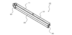
図1は、本発明の実施の形態における照明器具10の斜視図である。
図1に示すように、照明器具10は、器具本体11および反射板12を備えている。器具本体11の長手方向の両端には、同じ仕様のランプソケット30がそれぞれ設けられ、ランプソケット30に直管形LEDランプ20が着脱可能に装着される。反射板12は、直管形LEDランプ20から発せられる光を配光する機能を有する。また、照明器具10は、直管形LEDランプ20を点灯させるための電源を供給する電源装置(図示せず)を備えている。
FIG. 1 is a perspective view of a
As shown in FIG. 1, the
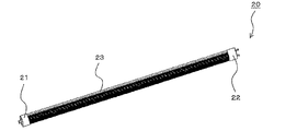
図2は、本発明の実施の形態における直管形LEDランプ20の一例を示す斜視図である。
図3は、本発明の実施の形態における直管形LEDランプ20の給電側口金22の拡大図である。
図4は、本発明の実施の形態における直管形LEDランプ20の接地側口金21の拡大図である。
図2に示すように、直管形LEDランプ20は、外郭23、ならびに外郭23の両端にそれぞれ設けられた給電側口金22および接地側口金21を備えている。外郭23は、内部に光源となるLEDモジュールを備え、その光を透過する構成となっている。
FIG. 2 is a perspective view showing an example of the straight
FIG. 3 is an enlarged view of the power
FIG. 4 is an enlarged view of the ground-
As shown in FIG. 2, the straight
本実施の形態の給電側口金22および接地側口金21は、JEL801規格に準拠したGX16t−5口金である。詳しくは、図3に示すように、給電側口金22は一対(2本)のL字形状の給電ピン25を有する。給電ピン25は、給電側口金22の給電側当接面24から軸方向に延びる給電ピン軸部25aと、給電ピン軸部25aの先端から外方向に延びる給電ピン抜け止め部25bとからなる。
The power
また、図4に示すように、接地側口金21は、1本の接地ピン27を有する。接地ピン27は、接地側口金21の接地側当接面26から軸方向に延びる接地ピン軸部27aと、接地ピン軸部27aの先端に形成される楕円形状の接地ピン先端部27bとからなる。接地ピン27を中心に対向する両側部には円形の接地側当接面26から凸状に形成された一対の接地側口金突起28(28a、28b)が形成されている。また、接地側口金突起28の外側側面は円弧面28cで構成されている。なお、接地側口金突起28の形状は特段限定されるものではなく、例えば円柱形状や直方体形状を採用することができる。
As shown in FIG. 4, the
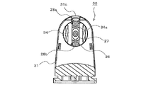
図5は、本発明の実施の形態におけるランプソケット30の分解斜視図である。
本実施の形態のランプソケット30は、直管形LEDランプ20の両端において一対配置されており、給電側口金22および接地側口金21の両方が装着可能な同一構造の構成となっている。図5に示すように、ランプソケット30は、上面が円弧形状の略箱体の形状を有し、給電側口金22および接地側口金21が装着される本体31と、その背面側を覆うカバー32とで構成されている。また、本体31とカバー32との間には、一対の導電接触片33(33a、33b)、および回転子34が配置され収納される。
FIG. 5 is an exploded perspective view of the
A pair of
本体31は、ポリカーボネートなどの熱可塑性樹脂で形成される。本体31は、直管形LEDランプ20を装着する際に、給電側口金22および接地側口金21が当接する当接面部31aと、円弧形状に形成された側面部31bとを有する。当接面部31aには、略円形の開口部36が形成されている。また、側面部31bには略矩形形状の切欠き部31cが形成されている。カバー32は、本体31と同じく、ポリカーボネートなどの熱可塑性樹脂で形成され、例えば係合爪と係合穴等によって本体31に取り付けられている。
The
カバー32の内面には、隙間38aを介して円状に配置される複数のクリック感用リブ38が設けられる。本実施の形態では、0°、90°、180°および270°に設けられた隙間38aを介して4個のクリック感用リブ38が設けられる。クリック感用リブ38は、カバー32と同じポリカーボネートなどの熱可塑性樹脂で形成される。 On the inner surface of the cover 32, a plurality of click feeling ribs 38 arranged in a circle via gaps 38a are provided. In the present embodiment, four click feeling ribs 38 are provided through gaps 38a provided at 0 °, 90 °, 180 °, and 270 °. The click feeling rib 38 is formed of the same thermoplastic resin as the cover 32 such as polycarbonate.
回転子34は、略円筒形状を有し、ポリカーボネートなどの熱可塑性樹脂で形成される。回転子34は、本体31の開口部36の内面に回転可能に取り付けられ、開口部36に当接する円板部34aと、円板部34aを直径方向に貫通して形成される直方体凹形状のピン挿入溝34bとを有している。ピン挿入溝34bには、直管形LEDランプ20の装着時に一対の給電ピン25もしくは接地ピン27及び接地側口金突起28が収納される。
The
導電接触片33a、33bは、例えば、りん青銅などの導通性のある材質で形成されている。導電接触片33a、33bは、回転子34のピン挿入溝34bに挿入される一対の給電ピン25と共に本体31内で回転する回転子34の外周側において、回転子34を挟んで対向配置される。回転子34と導電接触片33a、33bとの間は離間しており、この間隙には直管形LEDランプ20がランプソケット30に装着されたときに一対の給電ピン25が位置し、給電ピン25外側面が一対の導電接触片33a、33bの内側面に当接するように構成されている。また、導電接触片33a、33bは、図示しない電源装置と電気的に配線接続されている。なお、電源装置は、一対のランプソケット30の両方に接続され、導電接触片33に電源を供給する。
The
次に、ランプソケット30における給電ピン25および接地ピン27の保持状態について、図5〜図9を参照して説明する。
図5におけるピン挿入溝34bが垂直方向となる回転子34の状態では、ピン挿入溝34bと切欠き部31cとが連通しており、給電ピン25、もしくは接地ピン27及び接地側口金突起28をピン挿入溝34b内に挿入することが可能に構成されている。
Next, the holding state of the
In the state of the
この回転子34の位置でランプソケット30に直管形LEDランプ20を装着する。
図5の状態で直管形LEDランプ20がランプソケット30に正しく装着されると、ピン挿入溝34bには、給電ピン25、もしくは接地ピン27及び接地側口金突起28が収納され、直管形LEDランプ20を回転させることにより回転子34が回動する状態となる。
The straight
When the straight tube
はじめに、給電側口金22側における給電ピン25の取り付けについて説明する。
図6は、本実施の形態におけるランプソケット30の導電接触片33a、33bと給電ピン25との接触状態を示す断面図である。
図6に示すように回転子34を図5の状態から直管形LEDランプ20を90°回転させることで回転子34が共に回転し、直管形LEDランプ20がランプソケット30に固定され、回転子34の外周側において給電ピン25と導電接触片33a、33bが接触する状態となる。この状態により、図示しない電源装置から導電接触片33を介して給電ピン25に電源が供給され、直管形LEDランプ20に通電する。
First, attachment of the
FIG. 6 is a cross-sectional view showing a contact state between the
As shown in FIG. 6, by rotating the straight
また、直管形LEDランプ20が90°回転されると、図6に示す回転子34に設けられた突起34cがクリック感用リブ38の隙間38aに嵌まり込み、クリック感を生じる。これにより、作業者が直管形LEDランプ20をランプソケット30に正しく装着できたことを認識することができる。
Further, when the straight
次に、接地側口金21側における接地ピン27の取り付けについて説明する。
図7及び図8は、接地ピン27の保持状態を示す図である。
図7は、本発明の実施の形態における直管形LEDランプ20の接地ピン27をランプソケット30に挿入した状態(0°)を示す立面図である。
図8は、本発明の実施の形態における直管形LEDランプ20の接地ピン27をランプソケット30に挿入した状態(0°)から90°回転した状態(正規の装着位置(90°))を示す立面図である。
Next, attachment of the
7 and 8 are diagrams showing the holding state of the
FIG. 7 is an elevational view showing a state (0 °) in which the
FIG. 8 shows a state in which the
図7に示すように、まず、接地ピン27及び接地側口金突起28が回転子34のピン挿入溝34bに挿入される。ランプソケット30に接地ピン27及び接地側口金突起28が挿入されたとき、接地ピン27より先に一方の接地側口金突起28が開口部36の内周縁に当接することにより、回転子34の中央部付近にて接地ピン27が保持される。
As shown in FIG. 7, first, the
図7に示す状態で、直管形LEDランプ20を回転させると、接地側口金突起28が回転子34と接触することにより、給電ピン25を回転させた時と同様に、直管形LEDランプ20の回転と共に回転子34が回転する。
そして、図8に示すように正規の装着位置(90°)となるまで回転子34を回動する。
When the straight
Then, as shown in FIG. 8, the
このように、ランプソケット30に給電側口金22および接地側口金21のどちらが挿入されても、回転子34が回動することにより、回転子34によって接地ピン27が保持され、直管形LEDランプ20の落下を防ぐことが可能となる。
As described above, regardless of which of the power
接地側口金21をランプソケット30に装着する際に回転子34が回転するのは、接地側口金突起28が回転子34に当接するためであり、接地ピン27は回転子34の回転に関与していない。また、正規の装着位置(90°)にあるとき、回転子34と接地側口金突起28との接触により直管形LEDランプ20はランプソケット30に固定され、接地ピン27自体は保持されていない。したがって、接地側口金21に接地ピン27がなくても、接地側口金21をランプソケット30に装着する際には同様の作用効果が得られる。
The reason why the
また、接地側口金突起28の高さは、装着させた時に回転子34の円板部34aの厚みを超えない寸法で形成する。これは、接地側口金突起28の高さが円板部34aの厚み以上である場合、直管形LEDランプ20を回転させたとき、導電接触片33と接地側口金突起28とが接触し、導電接触片33が変形等する可能性があるからである。例えば清掃等のため直管形LEDランプ20を取り外し再度取り付ける際に、導電接触片33が変形したランプソケット30側に給電側口金22の給電ピン25が装着されると、給電ピン25と導電接触片33とが接触しない可能性があり、不点灯となる不都合が考えられる。
Further, the height of the ground side cap projection 28 is formed so as not to exceed the thickness of the
図9は、本発明の実施の形態における直管形LEDランプ20の接地ピン27をランプソケット30に挿入した状態(0°)から90°回転した状態(正規の装着位置(90°))を示す断面図である。
図9に示すように、接地ピン27は回転させても導電接触片33との間に隙間37a、37bが介在し互いに接触しない位置関係となるため、導電接触片33を変形させる可能性がない。また、接地側口金突起28は導電接触片33と接触しないため、電気的に接続されることもない。
FIG. 9 shows a state in which the
As shown in FIG. 9, even if the
直管形LEDランプ20が正規の装着位置(90°)にあるとき、接地側口金突起28がランプソケット30の開口部36の対向する内周縁に当接しており、接地側口金21の動きが制限される為、直管形LEDランプ20の振動等による水平方向へのガタつきを防止することができる。
また、接地側口金突起28の開口部36と接する面は、開口部36の内周縁の曲面に合わせた円弧形状の円弧面28cとなっているため、開口部36の内周縁と摺動可能に密着することにより、より接地側口金21のガタつきを防止することができる。
When the straight tube
Further, the surface of the grounding side base projection 28 that contacts the
上記のように、本実施の形態では、ランプソケット30に給電ピン25および接地ピン27のどちらが挿入されても、給電ピン25または接地側口金突起28を回転子34によって保持することができる。また、両方のランプソケット30の導電接触片33a、33bには、電源装置から電源が供給されているため、どちらのランプソケット30に給電ピン25が挿入されても、直管形LEDランプ20を点灯させることができる。
As described above, in the present embodiment, the
これにより、従来はJIS C7709−1準拠のGX16t−5口金を有した直管形LEDランプ20を点灯させるのに、給電側ソケットと接地側ソケットの2種類のランプソケット30が必要であったが、ランプソケット30を共通化することができる。よって、ランプソケット30や直管形LEDランプ20の取り付け作業時に取り付け方向性がなくなり、作業性が向上するとともに配線作業も統一され、作業ミスの発生を低減することが可能となる。
As a result, conventionally, in order to light up the straight tube
また、部品を共通化することで、部品点数や部品コストを低減することが可能となる。さらに、製造工程において、ソケットの選別工程、管理工程等が不要となり、さらにソケットの取り付け間違い等を防ぐことが可能となる。従って、製造にかかるコストの削減が可能となり、照明器具10を安価に製造することができる。
Also, by sharing parts, the number of parts and part cost can be reduced. Further, in the manufacturing process, a socket selection process, a management process, and the like are not necessary, and it is possible to prevent a socket attachment error and the like. Therefore, it is possible to reduce the manufacturing cost, and the
さらに、図10に示すような従来の接地側ソケット40に接地ピン27を保持する場合には、直管形LEDランプ20を回転することで接地ピン27が回転し、接触片41により接地ピン27を保持している。しかし、直管形LEDランプ20の回転不足等により正規の装着位置(90°)にない場合、接触片41からの応力により接地ピン27が回転しやすく、直管形LEDランプ20が回転して落下につながることがあった。
これに対し、本実施の形態では、回転子34と接地側口金突起28とによって接地ピン27を保持することにより、落下を防止するとともに振動等によるガタつきを防止することができる。
Further, when the
On the other hand, in the present embodiment, the
なお、接地ピン27は、直管形LEDランプ20をアース接続するためのピンとして説明したが、直管形LEDランプ20をランプソケット30に保持する単なる保持ピンとして使用することができる。よって、上記実施の形態に記載した接地側口金21、接地側当接面26、接地ピン27、接地側口金突起28(28a、28b)は、本発明における保持側口金、保持側当接面、保持ピン、保持側口金突起にそれぞれ相当する。
また、上記実施の形態においては、1灯用のランプソケットついて説明したが、2灯用以上のランプソケットについても、本発明を適用することが可能である。
The
In the above embodiment, the lamp socket for one lamp has been described, but the present invention can be applied to lamp sockets for two or more lamps.
10 照明器具、11 器具本体、12 反射板、20 直管形LEDランプ、21 接地側口金(保持側口金)、22 給電側口金、23 外郭、24 給電側当接面、25 給電ピン、25a 給電ピン軸部、25b 給電ピン抜け止め部、26 接地側当接面(保持側当接面)、27 接地ピン(保持ピン)、27a 接地ピン軸部、27b 接地ピン先端部、28(28a、28b) 接地側口金突起(保持側口金突起)、28c 円弧面、30 ランプソケット、31 本体、31a 当接面部、31b 側面部、31c 切欠き部、32 カバー、33(33a、33b) 導電接触片、34 回転子、34a 円板部、34b ピン挿入溝、34c 突起、36 開口部、37a 隙間、37b 隙間、38 クリック感用リブ、38a 隙間、40 接地側ソケット、41 接触片。
DESCRIPTION OF
Claims (6)
前記保持側口金は前記保持ピンが配置される保持側当接面を有し、
前記保持側当接面における前記保持ピンを中心に対向する両側部には、一対の保持側口金突起が形成されていることを特徴とする直管形ランプ。 A straight tube lamp comprising a power supply side base having a pair of power supply pins and a holding side base having one holding pin,
The holding side cap has a holding side contact surface on which the holding pin is disposed,
A straight tube lamp characterized in that a pair of holding-side cap projections are formed on both sides of the holding-side contact surface facing the holding pin as a center.
前記保持側口金突起における前記保持側当接面の外周側は、円弧面として形成されていることを特徴とする請求項1に記載の直管形ランプ。 The holding-side contact surface is formed in a circular shape,
2. The straight tube lamp according to claim 1, wherein an outer peripheral side of the holding-side contact surface of the holding-side base projection is formed as an arcuate surface.
前記給電側口金と前記保持側口金との両方を取り付け可能に構成した同一構造である一対のランプソケットを両端部に配置したことを特徴とする照明器具。 A lighting fixture equipped with the straight tube lamp according to claim 1 or 2 ,
A lighting fixture, wherein a pair of lamp sockets having the same structure in which both the power supply side base and the holding side base can be attached are arranged at both ends.
本体と、
前記本体に回転可能に取り付けられ、前記給電ピンと前記保持側口金突起との両方を保持可能な回転子と、
を備えることを特徴とする請求項3に記載の照明器具。 The lamp socket is
The body,
A rotor that is rotatably attached to the main body, and that can hold both the power supply pin and the holding-side base projection;
The lighting fixture according to claim 3 , comprising:
前記保持側口金突起を前記回転子に保持した際に、前記保持側口金突起の前記円弧面は、前記開口部の内周縁と当接する位置となることを特徴とする請求項2に従属する請求項4に記載の照明器具。 The main body has a circular opening that communicates with the rotor,
3. The subordinate to claim 2, wherein when the holding-side base projection is held by the rotor, the arc surface of the holding-side base projection is in a position to contact the inner peripheral edge of the opening. Item 5. A lighting apparatus according to Item 4 .
Priority Applications (1)
| Application Number | Priority Date | Filing Date | Title |
|---|---|---|---|
| JP2014192935A JP6358908B2 (en) | 2014-09-22 | 2014-09-22 | Straight tube lamp and luminaire |
Applications Claiming Priority (1)
| Application Number | Priority Date | Filing Date | Title |
|---|---|---|---|
| JP2014192935A JP6358908B2 (en) | 2014-09-22 | 2014-09-22 | Straight tube lamp and luminaire |
Publications (3)
| Publication Number | Publication Date |
|---|---|
| JP2016066414A JP2016066414A (en) | 2016-04-28 |
| JP2016066414A5 JP2016066414A5 (en) | 2017-09-14 |
| JP6358908B2 true JP6358908B2 (en) | 2018-07-18 |
Family
ID=55805694
Family Applications (1)
| Application Number | Title | Priority Date | Filing Date |
|---|---|---|---|
| JP2014192935A Expired - Fee Related JP6358908B2 (en) | 2014-09-22 | 2014-09-22 | Straight tube lamp and luminaire |
Country Status (1)
| Country | Link |
|---|---|
| JP (1) | JP6358908B2 (en) |
Family Cites Families (4)
| Publication number | Priority date | Publication date | Assignee | Title |
|---|---|---|---|---|
| JP2011198709A (en) * | 2010-03-23 | 2011-10-06 | Panasonic Electric Works Co Ltd | Light source, lamp socket, and illumination device using lamp socket |
| JP5984596B2 (en) * | 2012-09-18 | 2016-09-06 | 三菱電機株式会社 | Sockets and lighting fixtures |
| JP6020808B2 (en) * | 2012-09-24 | 2016-11-02 | 東芝ライテック株式会社 | Lamp system |
| JP2014086181A (en) * | 2012-10-19 | 2014-05-12 | Iris Ohyama Inc | Lighting device |
-
2014
- 2014-09-22 JP JP2014192935A patent/JP6358908B2/en not_active Expired - Fee Related
Also Published As
| Publication number | Publication date |
|---|---|
| JP2016066414A (en) | 2016-04-28 |
Similar Documents
| Publication | Publication Date | Title |
|---|---|---|
| JP2017033760A (en) | Socket and lighting apparatus | |
| JP2017091968A (en) | Socket and illumination apparatus | |
| WO2012043585A1 (en) | Socket and lighting device | |
| US8777464B2 (en) | Rotatable illumination device | |
| JP6020808B2 (en) | Lamp system | |
| JP6358908B2 (en) | Straight tube lamp and luminaire | |
| JP5440800B2 (en) | socket | |
| JP2012074143A (en) | Socket and luminaire | |
| JP5660383B2 (en) | Straight tube lamp and luminaire | |
| JP6395523B2 (en) | Lamp socket and luminaire | |
| JP6114576B2 (en) | Lamp system | |
| JP5725991B2 (en) | Lamp socket and lighting fixture | |
| JP5769035B2 (en) | Socket and lighting device | |
| JP5807169B2 (en) | lamp | |
| JP6380760B2 (en) | Lighting device | |
| JP2016110955A (en) | Lighting device | |
| JP6095285B2 (en) | Cap for straight tube lamp and method for manufacturing straight tube lamp | |
| JP6222466B2 (en) | Lamp apparatus and lighting apparatus | |
| JP6465148B2 (en) | Straight tube lamp and luminaire | |
| JP2015185388A (en) | Socket, non-power supply side socket, and lighting device | |
| JP5853726B2 (en) | Lamp socket and lighting device | |
| JP6289133B2 (en) | Socket and lighting apparatus using the same | |
| JP5915912B2 (en) | Straight tube lamp and luminaire | |
| WO2013175685A1 (en) | Socket and lighting fixture employing said socket | |
| JP6137564B2 (en) | Straight tube lamp and luminaire |
Legal Events
| Date | Code | Title | Description |
|---|---|---|---|
| A521 | Request for written amendment filed |
Free format text: JAPANESE INTERMEDIATE CODE: A523 Effective date: 20170801 |
|
| A621 | Written request for application examination |
Free format text: JAPANESE INTERMEDIATE CODE: A621 Effective date: 20170801 |
|
| A977 | Report on retrieval |
Free format text: JAPANESE INTERMEDIATE CODE: A971007 Effective date: 20180514 |
|
| TRDD | Decision of grant or rejection written | ||
| A01 | Written decision to grant a patent or to grant a registration (utility model) |
Free format text: JAPANESE INTERMEDIATE CODE: A01 Effective date: 20180522 |
|
| A61 | First payment of annual fees (during grant procedure) |
Free format text: JAPANESE INTERMEDIATE CODE: A61 Effective date: 20180619 |
|
| R150 | Certificate of patent or registration of utility model |
Ref document number: 6358908 Country of ref document: JP Free format text: JAPANESE INTERMEDIATE CODE: R150 |
|
| R250 | Receipt of annual fees |
Free format text: JAPANESE INTERMEDIATE CODE: R250 |
|
| LAPS | Cancellation because of no payment of annual fees |