EP2839807A1 - Dental prosthesis, in particular on implants, optionally for the replacement of an entire dental arch, method and kit for making it - Google Patents
Dental prosthesis, in particular on implants, optionally for the replacement of an entire dental arch, method and kit for making it Download PDFInfo
- Publication number
- EP2839807A1 EP2839807A1 EP14181913.6A EP14181913A EP2839807A1 EP 2839807 A1 EP2839807 A1 EP 2839807A1 EP 14181913 A EP14181913 A EP 14181913A EP 2839807 A1 EP2839807 A1 EP 2839807A1
- Authority
- EP
- European Patent Office
- Prior art keywords
- fibres
- mould
- molding cavity
- chewing
- thermosetting resin
- Prior art date
- Legal status (The legal status is an assumption and is not a legal conclusion. Google has not performed a legal analysis and makes no representation as to the accuracy of the status listed.)
- Granted
Links
- 239000007943 implant Substances 0.000 title claims abstract description 29
- 210000002455 dental arch Anatomy 0.000 title claims abstract description 26
- 238000000034 method Methods 0.000 title claims abstract description 18
- 230000001055 chewing effect Effects 0.000 claims abstract description 55
- OKTJSMMVPCPJKN-UHFFFAOYSA-N Carbon Chemical compound [C] OKTJSMMVPCPJKN-UHFFFAOYSA-N 0.000 claims abstract description 32
- 229910021389 graphene Inorganic materials 0.000 claims abstract description 20
- 229910052799 carbon Inorganic materials 0.000 claims abstract description 12
- 210000001519 tissue Anatomy 0.000 claims abstract description 7
- 238000000465 moulding Methods 0.000 claims description 33
- 229920005989 resin Polymers 0.000 claims description 29
- 239000011347 resin Substances 0.000 claims description 29
- 229920001187 thermosetting polymer Polymers 0.000 claims description 28
- 239000000945 filler Substances 0.000 claims description 16
- 239000002245 particle Substances 0.000 claims description 11
- 239000011859 microparticle Substances 0.000 claims description 7
- 239000003365 glass fiber Substances 0.000 claims description 6
- 238000005470 impregnation Methods 0.000 claims description 5
- 239000000463 material Substances 0.000 claims description 5
- 239000000835 fiber Substances 0.000 claims description 4
- 238000003780 insertion Methods 0.000 claims description 4
- 230000037431 insertion Effects 0.000 claims description 4
- 229920001296 polysiloxane Polymers 0.000 claims description 4
- 238000003825 pressing Methods 0.000 claims description 2
- 238000007670 refining Methods 0.000 claims 1
- 239000011521 glass Substances 0.000 abstract 1
- 239000002184 metal Substances 0.000 description 10
- 230000008878 coupling Effects 0.000 description 5
- 238000010168 coupling process Methods 0.000 description 5
- 238000005859 coupling reaction Methods 0.000 description 5
- 239000011152 fibreglass Substances 0.000 description 3
- 239000000126 substance Substances 0.000 description 3
- 230000015572 biosynthetic process Effects 0.000 description 2
- 235000013305 food Nutrition 0.000 description 2
- 229920000178 Acrylic resin Polymers 0.000 description 1
- 239000004925 Acrylic resin Substances 0.000 description 1
- 238000004026 adhesive bonding Methods 0.000 description 1
- 230000004931 aggregating effect Effects 0.000 description 1
- 230000005540 biological transmission Effects 0.000 description 1
- 210000000988 bone and bone Anatomy 0.000 description 1
- 230000001010 compromised effect Effects 0.000 description 1
- 238000010276 construction Methods 0.000 description 1
- 238000013016 damping Methods 0.000 description 1
- 230000000694 effects Effects 0.000 description 1
- 239000003822 epoxy resin Substances 0.000 description 1
- LNEPOXFFQSENCJ-UHFFFAOYSA-N haloperidol Chemical compound C1CC(O)(C=2C=CC(Cl)=CC=2)CCN1CCCC(=O)C1=CC=C(F)C=C1 LNEPOXFFQSENCJ-UHFFFAOYSA-N 0.000 description 1
- 238000010438 heat treatment Methods 0.000 description 1
- 210000001847 jaw Anatomy 0.000 description 1
- 238000005304 joining Methods 0.000 description 1
- 210000004373 mandible Anatomy 0.000 description 1
- 239000007769 metal material Substances 0.000 description 1
- 210000004877 mucosa Anatomy 0.000 description 1
- 229920000647 polyepoxide Polymers 0.000 description 1
- 229920001225 polyester resin Polymers 0.000 description 1
- 239000004645 polyester resin Substances 0.000 description 1
- 239000007787 solid Substances 0.000 description 1
- 238000005728 strengthening Methods 0.000 description 1
- 229920001567 vinyl ester resin Polymers 0.000 description 1
Images




Classifications
-
- A—HUMAN NECESSITIES
- A61—MEDICAL OR VETERINARY SCIENCE; HYGIENE
- A61C—DENTISTRY; APPARATUS OR METHODS FOR ORAL OR DENTAL HYGIENE
- A61C8/00—Means to be fixed to the jaw-bone for consolidating natural teeth or for fixing dental prostheses thereon; Dental implants; Implanting tools
- A61C8/0012—Means to be fixed to the jaw-bone for consolidating natural teeth or for fixing dental prostheses thereon; Dental implants; Implanting tools characterised by the material or composition, e.g. ceramics, surface layer, metal alloy
-
- A—HUMAN NECESSITIES
- A61—MEDICAL OR VETERINARY SCIENCE; HYGIENE
- A61C—DENTISTRY; APPARATUS OR METHODS FOR ORAL OR DENTAL HYGIENE
- A61C13/00—Dental prostheses; Making same
- A61C13/0003—Making bridge-work, inlays, implants or the like
- A61C13/0006—Production methods
- A61C13/001—Electrophoresis coating
-
- A—HUMAN NECESSITIES
- A61—MEDICAL OR VETERINARY SCIENCE; HYGIENE
- A61C—DENTISTRY; APPARATUS OR METHODS FOR ORAL OR DENTAL HYGIENE
- A61C13/00—Dental prostheses; Making same
- A61C13/01—Palates or other bases or supports for the artificial teeth; Making same
- A61C13/04—Palates or other bases or supports for the artificial teeth; Making same made by casting
-
- A—HUMAN NECESSITIES
- A61—MEDICAL OR VETERINARY SCIENCE; HYGIENE
- A61C—DENTISTRY; APPARATUS OR METHODS FOR ORAL OR DENTAL HYGIENE
- A61C13/00—Dental prostheses; Making same
- A61C13/08—Artificial teeth; Making same
- A61C13/081—Making teeth by casting or moulding
-
- A—HUMAN NECESSITIES
- A61—MEDICAL OR VETERINARY SCIENCE; HYGIENE
- A61C—DENTISTRY; APPARATUS OR METHODS FOR ORAL OR DENTAL HYGIENE
- A61C13/00—Dental prostheses; Making same
- A61C13/10—Fastening of artificial teeth to denture palates or the like
- A61C13/1003—Fastening of artificial teeth to denture palates or the like by embedding in base material
-
- A—HUMAN NECESSITIES
- A61—MEDICAL OR VETERINARY SCIENCE; HYGIENE
- A61C—DENTISTRY; APPARATUS OR METHODS FOR ORAL OR DENTAL HYGIENE
- A61C13/00—Dental prostheses; Making same
- A61C13/20—Methods or devices for soldering, casting, moulding or melting
- A61C13/206—Injection moulding
Definitions
- the present invention refers to a dental prosthesis, in particular on implants, optionally for the replacement of an entire dental arch.
- the present invention furthermore, refers to a method for obtaining a dental prosthesis, in particular on implants, optionally for the replacement of an entire dental arch.
- Another object of the present invention is a kit for obtaining a dental prosthesis, in particular on implants, optionally for the replacement of an entire dental arch.
- the present invention is suitable for being used in the field of dentistry and, in particular, it refers to dental prostheses that are intended for the partial and/or total replacement of natural dental arches of patients.
- dental prostheses are products, which are made in dentistry to replace lost or compromised original sets of teeth.
- various dental prostheses that can be made total dental prostheses are provided, which discharge the chewing loads on the mucosa and/or on the bone beneath and the task of which is to entirely re-establish the chewing functions of the patient.
- the aforementioned metal sub-structures are made so as to enclose the turrets and/or similar hooking elements in the supporting endosteal implants that are applied to the mandible and/or jaw bone tissue of the patient, allowing it to be stably fixed.
- the Applicant has found that the metal sub-structures are not capable of equally distributing the chewing loads on the endosteal support implants provided in the mouths of the patients, with the risk of damaging such implants and/or tearing the tissues of the patients on which they are anchored.
- the metal sub-structures transmit, during chewing, the chewing loads directly on the support endosteal implants, in a way that is identical to how they receive them. Therefore, the endosteal implants are considerably stressed during chewing with unpleasant consequences in terms of structural integrity and its configuration.
- the metal sub-structures are not therefore capable of absorbing in any way even a part of the chewing loads that are generated during chewing.
- the high mass of dental prostheses with metal sub-structures makes the patient tired quickly when chewing food products.
- the main purpose of the present invention is to provide a dental prosthesis, in particular on implants, optionally for the replacement of an entire dental arch, a method and a kit for making it, that is capable of solving the problems of the prior art.
- One purpose of the present invention is to provide a dental prosthesis that is highly resistant.
- a further purpose of the present invention is to propose a dental prosthesis that is considerably light.
- One purpose of the present invention is to provide a dental prosthesis the structure of which is capable of equally distributing the chewing loads on the endosteal implants of the patient.
- a further purpose of the present invention is to propose a dental prosthesis the structure of which is capable of absorbing and/or damping a part of the chewing load that is generated when chewing.
- Another purpose of the present invention is to provide a dental prosthesis that is easy to make.
- a further purpose of the present invention is to propose a dental prosthesis that can be made quickly.
- Another purpose of the present invention is to provide a dental prosthesis that does not require the dental technician to be highly experienced.
- a dental prosthesis in particular on implants, optionally for the replacement of an entire dental arch, a method and a kit for making it, as expressed and described in the following claims.
- a dental prosthesis in particular on implants, optionally for the replacement of an entire dental arch, a method and a kit for making it, in accordance with the present invention.
- number 1 wholly indicates a dental prosthesis, in particular on implants, optionally for the replacement of an entire dental arch, in accordance with the present invention.
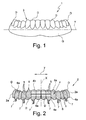
- the dental prosthesis 1, represented in figure 1 comprises a plurality of teeth D that are arranged side by side to each other along an arched development that reproduces the natural curvature of the dental arch of a patient and a gingival portion G that is engaged with the teeth D along an edge of the dental prosthesis 1 itself.
- the dental prosthesis 1 comprises a load-bearing structure 2 that is suitable for supporting the aesthetic part 3 ( figure 1 ) that is made on it.
- the structure 2 mainly extends along a direction Y ( figures 1, 2 , 8 and 12 ), advantageously according to a substantially arched development, and has at least one chewing portion 4 that develops transverse with respect to the structure 2.
- the chewing portion 4 is made in a single piece with the structure 2 and substantially has the shape of a tooth or of a dental arch.
- chewing portion 4 we mean the part of structure 2 that extends according to a direction of main development X ( figure 2 ) between a contact edge 4a, which is suitable for engaging the tissues of the patient, and a chewing edge 4b, which is opposite the contact edge 4a, which is intended for chewing food products.
- the chewing portion 4 of the structure 2 reproduces, for each tooth D, an entire dental arch of the patient.
- the structure 2 is obtained by using a plurality of fibres 5 ( figure 2 ), optionally carbon fibres and/or glass fibres, which are suitably impregnated with a suitable thermosetting resin 5a.
- the fibres 5 used can be graphene fibres, preferably in the form of agglomerate sheets of particles of graphene.
- the agglomerate sheets of graphene have an average thickness of between 10nm and 200nm (nanometres).
- the graphene fibres 5 and/or the particles of graphene can be used individually, or in combination with carbon fibres 5 and/or fibre glass 5, according to the contingent requirements.
- the fibres 5 extend along the direction of development Y of the structure 2 advantageously transverse with respect to the main direction of development X of the chewing portion 4.
- the fibres 5 of the structure 2 extend unidirectionally transverse with respect to the teeth D of the chewing portion 4 defined by the latter, following the curvature and the arched development of the dental arch to be reproduced.
- the fibres 5 are advantageously superimposed and/or adjacent one another, from one end 2a to the other of the structure 2, developing, transverse with respect to the main development direction X of the chewing portion 4, which is substantially parallel with respect to one another.
- the fibres 5 which the structure 2 is made of can be interlaced. Also in this situation, the orientation of the fibres 5 remains transverse with respect to the chewing portion 4 despite of the fact that they cross one another along the longitudinal development Y of the structure 2.
- the carbon fibres used for making the structure 2 have a flexural modulus of between, 250.000Mpa and 450.000Mpa.
- the elastic modulus of the latter is of between 70.000Mpa and 110.000Mpa.
- both the chewing edge 4b and the contact edge 4a of the chewing portion 4 of the structure 2 are made by at least one filler thermosetting resin 6 ( figure 2 ), which is optionally filled with microparticles 6a, in particular of a length comprised between 10 ⁇ m and 6mm, preferably between 15 ⁇ m and 25 ⁇ m, even more preferably between 18 ⁇ m and 22 ⁇ m, obtained from the chopping of the fibres 5 that can be used for obtaining the structure 2, and/or filled with graphene particles.
- a filler thermosetting resin 6 figure 2
- microparticles 6a in particular of a length comprised between 10 ⁇ m and 6mm, preferably between 15 ⁇ m and 25 ⁇ m, even more preferably between 18 ⁇ m and 22 ⁇ m, obtained from the chopping of the fibres 5 that can be used for obtaining the structure 2, and/or filled with graphene particles.
- the average thickness of the graphene particles is advantageously of between 2nm and 20nm (nanometres).
- the thermosetting resins that can be used to obtain the structure 2 of the dental prosthesis 1 can comprise epoxy resins, vinyl ester, polyester and acrylic resins. It should however be noted that the use of other resins and/or of similar aggregating substances that are capable of carrying out the same tasks can be contemplated for the purposes of the invention.
- the structure 2 comprises at least one hooking element 7, preferably a plurality of hooking elements 7, engaged, in particular integrated, in the structure 2 itself and engageable to respective endosteal implants (which are not represented because they are of the known type) applied inside the mouth of a patient for fixing the dental prosthesis 1 to the tissues of the patient.
- each hooking element 7 comprises a respective turret that is substantially cylindrical for fixing the dental prosthesis 1 to the endosteal implants of the patient.
- each hooking element 7 develops, at least partially, inside the chewing portion 4 along the main development direction X of the latter, transverse with respect to the fibres 5 that form the structure 2.
- the structure 2 of the dental prosthesis 1 is made according to a method that provides a mould 100 ( figures 3, 4 , 7 and 9 ) that is provided with at least one hooking element 7, preferably a plurality of hooking elements 7, which are suitable for engaging respective endosteal implants that are applied into the mouth of a patient and for fixing the prosthesis to the tissues of the latter, and the provision of a counter-mould 101 ( figures 6 to 8 ) in which at least one molding cavity 101a is defined, having, in negative, the shape of the structure 2 or of a chewing portion 4 of the dental arch of the patient to be reproduced or the shape of the entire dental arch thereof.
- the provision of the mould 100 is provided by making a model 103, in positive, of the dental arch of the patient to be reproduced, said model 103 being provided with hooking elements 7 on which respective additional elements 104 are engaged, preferably made in silicone and/or in a similar material, and each having at least one respective sharp-pointed portion 104a, optionally conical or wedge-shaped, projecting from the model 103 itself.
- the provision of the counter-mould 101 is carried out by filling the latter with a deformable material 105, preferably silicone for dentistry, and by coupling on it the mould 100 carrying the model 103 that is prepared beforehand with the hooking elements and the additional elements 104.
- a deformable material 105 preferably silicone for dentistry
- the coupling between the mould 100 and counter-mould 101 determines the formation, in the deformable material 105, of the aforementioned molding cavity 101a ( figure 8 ) that reproduces in negative the shape of the chewing portion 4 or of the entire set of teeth of the patient to be reproduced, corresponding to the model 103 provided with hooking elements 7 and with additional elements 104.
- the molding cavity 101a has: a relative depth P ( figure 12 ) that is substantially at the height of the corresponding structure 2 and/or chewing portion 4 to be formed; a width M ( figures 8 and 11 ), relative to the thickness of the corresponding structure 2 and/or chewing portion 4 to be formed; and, a length L ( figure 8 ), relative to the amplitude of the corresponding structure 2 and/or chewing portion 4 to be made.
- a relative depth P figure 12
- a width M figures 8 and 11
- a length L figure 8
- the dimensions of the molding cavity 101a vary in function of the shape of the dental arch to be reproduced.
- the mould 100 is separated from the counter-mould 101.
- the additional elements 104 are removed from the model 103 engaged in the mould 100, so as to free the hooking elements 7 and to allow them to be released from the mould 100.
- the hooking elements 7 are removed from the model 103, so as to be located again in the mould 100 according to the same initial position.
- the arrangement of the hooking elements 7 is facilitated by the presence of a base (which is not illustrated being of the known type) which is inserted into the mould 100 and is almost totally covered with a deformable material 105 ( figures 3, 4 and 9 ), preferably silicone for dentistry, during its provision.
- the hooking elements 7 are positioned at an auxiliary forming cavity 106 which is defined in the mould 100, to complete the molding cavity 101a of the counter-mould 101, after coupling the mould 100 with the counter-mould 101.
- the additional elements 104 are applied onto the hooking elements 7, as illustrated in figure 9 .
- the repositioning of the hooking elements 7 with the respective additional elements 104 determines the end of the provision of the mould 100.
- the plurality of fibres 5 is arranged, at least partially, preferably entirely, into the molding cavity 101a of the counter-mould 101 ( figure 11 ) according to an orientation that is transverse with respect to the depth P ( figure 12 ) and to the width M ( figures 8 and 11 ) of the latter.
- a filler thermosetting resin 6 that is filled with micro particles 6a that are obtained from the chopping of the fibres 5 which can be used for obtaining the structure 2 of the dental prosthesis 1 being formed, is suitably provided and applied into the molding cavity 101a of the counter-mould 101, before the plurality of previously impregnated fibres 5 are inserted into the latter.
- the application of the filler thermosetting resin 6 is carried out on the bottom of the molding cavity 101a of the counter-mould 101 so as to faithfully reproduce the shape of the chewing edge 4b of the chewing portion 4.
- a predetermined amount of filler thermosetting resin 6 is then applied onto them, so as to define a covering layer ( figure 12 ) that is adapted to be pressed by the mould 100 during the engagement of the latter on the counter-mould 101.
- the mould 100 is again fixedly engaged to the counter-mould 101. In such a way, the hooking elements 7, together with the additional elements 104, are inserted into the molding cavity 101a of the counter-mould 101 between the fibres 5, in a transverse manner with respect to the latter.
- the sharp-pointed portions 104a of the additional elements 104 are inserted into the molding cavity 101a of the counter-mould 101 between the fibres 5 without damaging them and facilitating the insertion of the hooking elements 7.
- an upper layer of filler thermosetting resin 6 provided with micro particles 6a produces the effect, during the coupling between the mould 100 and the counter-mould 101, of eliminating possible air bubbles that can be formed during the impregnation step of the fibres 5.
- the upper layer of filler thermosetting resin 6, operates, upon mutual pressure of the mould 100 and of the counter-mould 101, like a press, pressing the fibres 5 transversally against the bottom of the molding cavity 101a of the counter-mould 100.
- Such a pressure action in addition to setting at best the fibres 5 in the molding cavity 101a, causes the breakage of all of the air bubbles possibly present inside such a cavity 101a.
- thermosetting resins 5a, 6 occurs by means of suitable known heating means, so as to make a respective solid structure 2, on which the chewing portion 4 is defined.
- the structure 2 is extracted from the mould 100 and from the counter-mould 101, so as to, subsequently, finish it off according to the construction of the final aesthetic part to be made.
- the dental prosthesis 1 mentioned above which is obtained by means of the method described, solves the problems of the prior art and obtains important advantages.
- the transverse arrangement of the fibres with respect to the hooking elements and, consequently, to the endosteal implants that are applied into the mouth of the patients, as well as the main development direction of the chewing portion and therefore the main chewing direction of the patients, permits an optimal arrangement of the chewing loads on the hooking elements themselves.
- the arrangement of bundles of fibres that develop unidirectionally transverse with respect to the teeth obtained allows to evenly distribute the chewing loads on the endosteal implants provided in the mouths of the patients.
- the transverse orientation of the aforementioned fibres gives the structure obtained a slight flexibility which allows it to absorb and/or partially dampen the aforementioned chewing loads thus reducing the stresses on the hooking elements and on the endosteal implants of the patients.
- a structure in carbon fibre can weigh about 3 or 4 grams, thus being considerably lower than the 35 or 40 grams of metal structures used for making known prostheses.
- the method for making the aforementioned dental prosthesis is simple and easy to make even by not particularly experienced dental technicians.
Landscapes
- Health & Medical Sciences (AREA)
- Oral & Maxillofacial Surgery (AREA)
- Life Sciences & Earth Sciences (AREA)
- Veterinary Medicine (AREA)
- Epidemiology (AREA)
- Animal Behavior & Ethology (AREA)
- General Health & Medical Sciences (AREA)
- Public Health (AREA)
- Dentistry (AREA)
- Engineering & Computer Science (AREA)
- Manufacturing & Machinery (AREA)
- Molecular Biology (AREA)
- Ceramic Engineering (AREA)
- Orthopedic Medicine & Surgery (AREA)
- Dental Prosthetics (AREA)
- Dental Tools And Instruments Or Auxiliary Dental Instruments (AREA)
Abstract
Description
- The present invention refers to a dental prosthesis, in particular on implants, optionally for the replacement of an entire dental arch.
- The present invention, furthermore, refers to a method for obtaining a dental prosthesis, in particular on implants, optionally for the replacement of an entire dental arch.
- Another object of the present invention is a kit for obtaining a dental prosthesis, in particular on implants, optionally for the replacement of an entire dental arch.
- The present invention is suitable for being used in the field of dentistry and, in particular, it refers to dental prostheses that are intended for the partial and/or total replacement of natural dental arches of patients.
- As it is known, dental prostheses are products, which are made in dentistry to replace lost or compromised original sets of teeth. Among the various dental prostheses that can be made total dental prostheses are provided, which discharge the chewing loads on the mucosa and/or on the bone beneath and the task of which is to entirely re-establish the chewing functions of the patient.
- Normally, making total prostheses is carried out by using respective suitably prepared models. With such models it is possible to obtain a sub-structure that is generally made of metal, on which the aesthetic part that reproduces the teeth of the patient is obtained as faithfully as possible.
- The aforementioned metal sub-structures are made so as to enclose the turrets and/or similar hooking elements in the supporting endosteal implants that are applied to the mandible and/or jaw bone tissue of the patient, allowing it to be stably fixed.
- Although it is widespread to make sub-structures in metal material when making total dental prostheses, the Applicant has found that making and using metal sub-structures, has drawbacks and can be improved in different aspects, mainly relating to the transmission of the chewing loads on the support endosteal implants, to the overall mass of the prosthesis made, as well as to the speed, ease and rapidity of making them.
- In particular, the Applicant has found that the metal sub-structures are not capable of equally distributing the chewing loads on the endosteal support implants provided in the mouths of the patients, with the risk of damaging such implants and/or tearing the tissues of the patients on which they are anchored.
- In addition, the metal sub-structures transmit, during chewing, the chewing loads directly on the support endosteal implants, in a way that is identical to how they receive them. Therefore, the endosteal implants are considerably stressed during chewing with unpleasant consequences in terms of structural integrity and its configuration.
- The metal sub-structures are not therefore capable of absorbing in any way even a part of the chewing loads that are generated during chewing.
- It should be furthermore noted that using metal considerably makes dental prostheses heavier, the overall mass of which can be appreciated directly by the patient whom it is applied to.
- The high mass of dental prostheses with metal sub-structures, the overall weight of which can vary from 35 grams to 40 grams, makes the patient tired quickly when chewing food products.
- In addition, it is not possible to make the aforementioned metal sub-structures rapidly and they require the dental technician involved to be highly experienced and competent.
- The main purpose of the present invention is to provide a dental prosthesis, in particular on implants, optionally for the replacement of an entire dental arch, a method and a kit for making it, that is capable of solving the problems of the prior art.
- One purpose of the present invention is to provide a dental prosthesis that is highly resistant.
- A further purpose of the present invention is to propose a dental prosthesis that is considerably light.
- One purpose of the present invention is to provide a dental prosthesis the structure of which is capable of equally distributing the chewing loads on the endosteal implants of the patient.
- A further purpose of the present invention is to propose a dental prosthesis the structure of which is capable of absorbing and/or damping a part of the chewing load that is generated when chewing.
- Another purpose of the present invention is to provide a dental prosthesis that is easy to make.
- A further purpose of the present invention is to propose a dental prosthesis that can be made quickly. Another purpose of the present invention is to provide a dental prosthesis that does not require the dental technician to be highly experienced.
- The purposes specified above, and others, are substantially achieved with a dental prosthesis, in particular on implants, optionally for the replacement of an entire dental arch, a method and a kit for making it, as expressed and described in the following claims. We shall now describe, as an example, a preferred but not exclusive embodiment of a dental prosthesis, in particular on implants, optionally for the replacement of an entire dental arch, a method and a kit for making it, in accordance with the present invention.
- The description shall be made in the rest of the description with reference to the attached drawings, given purely as an indication and therefore not for limiting purposes, in which:
-
figure 1 is a schematic view of a dental prosthesis, in particular on implants, optionally for the replacement of an entire dental arch, in accordance with the present invention; -
figure 2 is a schematic view of a load-bearing structure of the prosthesis according tofigure 1 ; -
figure 3 is a schematic representation of a mould that is provided with a model of a dental arch to be made; -
figure 4 is a schematic representation of the mould according tofigure 3 , in which the additional elements with a conical portion are applied to the hooking elements of the model carried by the mould; -
figure 5 is a perspective schematic representation in an exploded view of a hooking element and of a respective additional element that can be used for obtaining the prosthesis according to the present invention; -
figure 6 is a perspective schematic representation of a counter-mould that is filled with a deformable substance that is used in dentistry; -
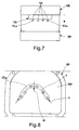
figure 7 is a representation of the coupling between the mould provided with a model according tofigure 3 and 4 , and a counter-mould according tofigure 6 ; -
figure 8 is a schematic representation of the counter-mould according tofigures 6 and7 , after making a molding cavity; -
figure 9 is a schematic representation of the mould according tofigures 3, 4 and7 , after removing the model and the repositioning of some components of the structure of the dental prosthesis; -
figure 10 is a schematic representation of the application of a thermosetting resin on a bundle of fibres; -
figure 11 is a schematic representation of the counter-mould according tofigures 6 to 8 , which is filled with a plurality of fibres that are impregnated with a thermosetting resin; -
figure 12 is a schematic section view of the counter-mould carried out according to the line XII-XII offigure 11 ; - With reference to
figure 1 ,number 1 wholly indicates a dental prosthesis, in particular on implants, optionally for the replacement of an entire dental arch, in accordance with the present invention. - The
dental prosthesis 1, represented infigure 1 , comprises a plurality of teeth D that are arranged side by side to each other along an arched development that reproduces the natural curvature of the dental arch of a patient and a gingival portion G that is engaged with the teeth D along an edge of thedental prosthesis 1 itself. - As visible in
figure 2 , thedental prosthesis 1 comprises a load-bearingstructure 2 that is suitable for supporting the aesthetic part 3 (figure 1 ) that is made on it. - The
structure 2 mainly extends along a direction Y (figures 1, 2 ,8 and12 ), advantageously according to a substantially arched development, and has at least onechewing portion 4 that develops transverse with respect to thestructure 2. - According to one advantageous aspect of the present invention, the
chewing portion 4 is made in a single piece with thestructure 2 and substantially has the shape of a tooth or of a dental arch. - In detail, by
chewing portion 4, we mean the part ofstructure 2 that extends according to a direction of main development X (figure 2 ) between acontact edge 4a, which is suitable for engaging the tissues of the patient, and achewing edge 4b, which is opposite thecontact edge 4a, which is intended for chewing food products. - Preferably, the
chewing portion 4 of thestructure 2 reproduces, for each tooth D, an entire dental arch of the patient. - According to one advantageous aspect of the present invention, the
structure 2 is obtained by using a plurality of fibres 5 (figure 2 ), optionally carbon fibres and/or glass fibres, which are suitably impregnated with a suitablethermosetting resin 5a. Advantageously, thefibres 5 used can be graphene fibres, preferably in the form of agglomerate sheets of particles of graphene. - Preferably, the agglomerate sheets of graphene have an average thickness of between 10nm and 200nm (nanometres).
- Alternatively it is possible for even single particles of graphene to be used, preferably having an average thickness of between 2nm and 20nm (nanometres).
- The
graphene fibres 5 and/or the particles of graphene can be used individually, or in combination withcarbon fibres 5 and/orfibre glass 5, according to the contingent requirements. - As visible in
figure 2 , thefibres 5 extend along the direction of development Y of thestructure 2 advantageously transverse with respect to the main direction of development X of thechewing portion 4. In detail, thefibres 5 of thestructure 2 extend unidirectionally transverse with respect to the teeth D of thechewing portion 4 defined by the latter, following the curvature and the arched development of the dental arch to be reproduced. - In particular, the
fibres 5 are advantageously superimposed and/or adjacent one another, from oneend 2a to the other of thestructure 2, developing, transverse with respect to the main development direction X of thechewing portion 4, which is substantially parallel with respect to one another. - It should not however be excluded that the
fibres 5 which thestructure 2 is made of can be interlaced. Also in this situation, the orientation of thefibres 5 remains transverse with respect to thechewing portion 4 despite of the fact that they cross one another along the longitudinal development Y of thestructure 2. Advantageously, the carbon fibres used for making thestructure 2 have a flexural modulus of between, 250.000Mpa and 450.000Mpa. - In the case in which fibre glass is used to make the
structure 2, the elastic modulus of the latter is of between 70.000Mpa and 110.000Mpa. - Preferably, both the
chewing edge 4b and thecontact edge 4a of thechewing portion 4 of thestructure 2 are made by at least one filler thermosetting resin 6 (figure 2 ), which is optionally filled withmicroparticles 6a, in particular of a length comprised between 10µm and 6mm, preferably between 15µm and 25µm, even more preferably between 18µm and 22µm, obtained from the chopping of thefibres 5 that can be used for obtaining thestructure 2, and/or filled with graphene particles. - The average thickness of the graphene particles is advantageously of between 2nm and 20nm (nanometres). Advantageously, the thermosetting resins that can be used to obtain the
structure 2 of thedental prosthesis 1 can comprise epoxy resins, vinyl ester, polyester and acrylic resins. It should however be noted that the use of other resins and/or of similar aggregating substances that are capable of carrying out the same tasks can be contemplated for the purposes of the invention. - Again with reference to
figure 2 , thestructure 2 comprises at least one hookingelement 7, preferably a plurality of hookingelements 7, engaged, in particular integrated, in thestructure 2 itself and engageable to respective endosteal implants (which are not represented because they are of the known type) applied inside the mouth of a patient for fixing thedental prosthesis 1 to the tissues of the patient. - In detail, each
hooking element 7 comprises a respective turret that is substantially cylindrical for fixing thedental prosthesis 1 to the endosteal implants of the patient. - Advantageously, each hooking
element 7 develops, at least partially, inside the chewingportion 4 along the main development direction X of the latter, transverse with respect to thefibres 5 that form thestructure 2. Thestructure 2 of thedental prosthesis 1 is made according to a method that provides a mould 100 (figures 3, 4 ,7 and9 ) that is provided with at least one hookingelement 7, preferably a plurality of hookingelements 7, which are suitable for engaging respective endosteal implants that are applied into the mouth of a patient and for fixing the prosthesis to the tissues of the latter, and the provision of a counter-mould 101 (figures 6 to 8 ) in which at least onemolding cavity 101a is defined, having, in negative, the shape of thestructure 2 or of a chewingportion 4 of the dental arch of the patient to be reproduced or the shape of the entire dental arch thereof. - As illustrated in
figures 3, 4 and7 , the provision of themould 100 is provided by making amodel 103, in positive, of the dental arch of the patient to be reproduced, saidmodel 103 being provided with hookingelements 7 on which respectiveadditional elements 104 are engaged, preferably made in silicone and/or in a similar material, and each having at least one respective sharp-pointedportion 104a, optionally conical or wedge-shaped, projecting from themodel 103 itself. - The provision of the counter-mould 101 is carried out by filling the latter with a
deformable material 105, preferably silicone for dentistry, and by coupling on it themould 100 carrying themodel 103 that is prepared beforehand with the hooking elements and theadditional elements 104. - The coupling between the
mould 100 andcounter-mould 101 determines the formation, in thedeformable material 105, of theaforementioned molding cavity 101a (figure 8 ) that reproduces in negative the shape of the chewingportion 4 or of the entire set of teeth of the patient to be reproduced, corresponding to themodel 103 provided with hookingelements 7 and withadditional elements 104. - As visible in
figures 8 ,11 and 12 , themolding cavity 101a has: a relative depth P (figure 12 ) that is substantially at the height of thecorresponding structure 2 and/or chewingportion 4 to be formed; a width M (figures 8 and11 ), relative to the thickness of thecorresponding structure 2 and/or chewingportion 4 to be formed; and, a length L (figure 8 ), relative to the amplitude of thecorresponding structure 2 and/or chewingportion 4 to be made. Of course, the dimensions of themolding cavity 101a vary in function of the shape of the dental arch to be reproduced. - Subsequently to making the
molding cavity 101a, themould 100 is separated from the counter-mould 101. Theadditional elements 104 are removed from themodel 103 engaged in themould 100, so as to free the hookingelements 7 and to allow them to be released from themould 100. - Once the hooking
elements 7 have been released from themould 100, it is possible to remove themodel 103. Advantageously, the hookingelements 7 are removed from themodel 103, so as to be located again in themould 100 according to the same initial position. The arrangement of the hookingelements 7 is facilitated by the presence of a base (which is not illustrated being of the known type) which is inserted into themould 100 and is almost totally covered with a deformable material 105 (figures 3, 4 and9 ), preferably silicone for dentistry, during its provision. - In detail, the hooking
elements 7 are positioned at an auxiliary formingcavity 106 which is defined in themould 100, to complete themolding cavity 101a of the counter-mould 101, after coupling themould 100 with the counter-mould 101. - Once the hooking
elements 7 have been fixed in the provided position inside themould 100, theadditional elements 104 are applied onto the hookingelements 7, as illustrated infigure 9 . - In detail, such an operation is carried out by inserting the
stem 104b (figure 5 ) of eachadditional element 104 into the respective hookingelement 7 and fixing them by means of glueing elements or similar joining substances. - The repositioning of the hooking
elements 7 with the respectiveadditional elements 104 determines the end of the provision of themould 100. - Subsequently, at least one plurality of
fibres 5, advantageously in the form of one or more bundles 107 (figure 10 ), is impregnated with athermosetting resin 5a. - Once they have been impregnated with the aforementioned
thermosetting resin 5a, the plurality offibres 5 is arranged, at least partially, preferably entirely, into themolding cavity 101a of the counter-mould 101 (figure 11 ) according to an orientation that is transverse with respect to the depth P (figure 12 ) and to the width M (figures 8 and11 ) of the latter. - The impregnation of the
fibres 5 with the suitablethermosetting resin 5a and the arrangement thereof into themolding cavity 101a of the counter-mould 101, are reiterated until a predetermined filling level has been reached, preferably until thesame molding cavity 101a has been completely filled. - In order to detect the details of the
molding cavity 101a of the counter-mould 101 while at the same time strengthening the chewingedge 4b of thestructure 2 being formed, afiller thermosetting resin 6 that is filled withmicro particles 6a that are obtained from the chopping of thefibres 5 which can be used for obtaining thestructure 2 of thedental prosthesis 1 being formed, is suitably provided and applied into themolding cavity 101a of the counter-mould 101, before the plurality of previously impregnatedfibres 5 are inserted into the latter. - In detail, as visible in the schematic section view of
figure 12 , the application of thefiller thermosetting resin 6 is carried out on the bottom of themolding cavity 101a of the counter-mould 101 so as to faithfully reproduce the shape of the chewingedge 4b of the chewingportion 4. - Once the
molding cavity 101a of the counter-mould 101 has been filled with thefibres 5, a predetermined amount of fillerthermosetting resin 6 is then applied onto them, so as to define a covering layer (figure 12 ) that is adapted to be pressed by themould 100 during the engagement of the latter on thecounter-mould 101. Once the covering layer in fillerthermosetting resin 6 has been applied, themould 100 is again fixedly engaged to the counter-mould 101. In such a way, the hookingelements 7, together with theadditional elements 104, are inserted into themolding cavity 101a of the counter-mould 101 between thefibres 5, in a transverse manner with respect to the latter. - While closing the
mould 100 on the counter-mould 101, the sharp-pointedportions 104a of theadditional elements 104 are inserted into themolding cavity 101a of the counter-mould 101 between thefibres 5 without damaging them and facilitating the insertion of the hookingelements 7. - The advantageous formation of an upper layer of filler
thermosetting resin 6 provided withmicro particles 6a produces the effect, during the coupling between themould 100 and the counter-mould 101, of eliminating possible air bubbles that can be formed during the impregnation step of thefibres 5. In detail, the upper layer of fillerthermosetting resin 6, operates, upon mutual pressure of themould 100 and of the counter-mould 101, like a press, pressing thefibres 5 transversally against the bottom of themolding cavity 101a of the counter-mould 100. Such a pressure action, in addition to setting at best thefibres 5 in themolding cavity 101a, causes the breakage of all of the air bubbles possibly present inside such acavity 101a. Once the mould has been locked, the hardening of thethermosetting resins solid structure 2, on which the chewingportion 4 is defined. Once the hardening step has ended, thestructure 2 is extracted from themould 100 and from the counter-mould 101, so as to, subsequently, finish it off according to the construction of the final aesthetic part to be made. - The
dental prosthesis 1 mentioned above, which is obtained by means of the method described, solves the problems of the prior art and obtains important advantages. - Firstly, the transverse arrangement of the fibres with respect to the hooking elements and, consequently, to the endosteal implants that are applied into the mouth of the patients, as well as the main development direction of the chewing portion and therefore the main chewing direction of the patients, permits an optimal arrangement of the chewing loads on the hooking elements themselves.
- In particular, the arrangement of bundles of fibres that develop unidirectionally transverse with respect to the teeth obtained, allows to evenly distribute the chewing loads on the endosteal implants provided in the mouths of the patients.
- Moreover, the transverse orientation of the aforementioned fibres gives the structure obtained a slight flexibility which allows it to absorb and/or partially dampen the aforementioned chewing loads thus reducing the stresses on the hooking elements and on the endosteal implants of the patients.
- It is also worth mentioning that the use of carbon fibres and/or of fibre glass and/or graphene fibre allows to considerably reduce the overall mass of the dental prosthesis produced, the lightness of which allows to tire the patient less during chewing.
- Indeed, a structure in carbon fibre can weigh about 3 or 4 grams, thus being considerably lower than the 35 or 40 grams of metal structures used for making known prostheses.
- It is also worth noting that the use of carbon fibres and/or graphene fibres provides the dental prosthesis with high resistance.
- In addition, the method for making the aforementioned dental prosthesis is simple and easy to make even by not particularly experienced dental technicians.
- It is also worth considering that the method described can be carried out rapidly since the arrangement of the fibre bundles in the molding cavity of the counter-mould only requires the fibres to be impregnated with the thermosetting resin and to be subsequently inserted into the molding cavity.
Claims (14)
- Dental prosthesis (1), in particular on implants, optionally for the replacement of an entire dental arch, said dental prosthesis (1) comprising:a structure (2) mainly extending along a direction (Y) and having at least one chewing portion (4) developing transverse to said structure (2);at least one, preferably a plurality of, hooking element (7), engaged, in particular integrated, in said structure (2) and engageable to a respective implant applied in the mouth of a patient for fixing said dental prosthesis (1) to the tissues of the latter;characterised in that said structure (2) is made through a plurality of fibres (5), optionally carbon fibres and/or glass fibres, developing along the development of said structure (2) transverse to the development of the chewing portion (4).
- Prosthesis according to claim 1, wherein the main development (Y) of said structure (2) is substantially arched, said fibres (5) being unidirectional and developing, transverse to the development of said chewing portion (4), substantially along the arched development of said structure (2).
- Prosthesis according to claim 1 or 2, wherein said fibres (5) are superimposed and/or adjacent transversally to the development of the chewing portion (4) of said structure (2) and along the arched development of said structure (2).
- Prosthesis according to one or more of the preceding claims wherein said structure (2) comprises at least one layer made through at least one filler thermosetting resin (6), optionally filled with micro particles (6a), in particular of length comprised between 10µm and 6mm, preferably between 15µm and 25µm, even more preferably between 18µm and 22µm, obtained from the chopping of the fibres (5) usable for obtaining said structure (2).
- Prosthesis according to one or more of the preceding claims, wherein said chewing portion (4) is made in a single piece with said structure (2) and is substantially tooth or dental-arch shaped, said chewing portion (4) developing according to a direction of main development (X) between a contact edge (4a) suitable for engaging the tissues of the patient and a chewing edge (4b) opposite said contact edge (4a), said chewing (4b) and/or contact (4a) edges being made through said a filler thermosetting resin (6) which is filled with micro particles of fibre.
- Prosthesis according to one or more of the preceding claims, wherein each hooking element (7) develops, at least partially, within said structure (2), said fibres (5) being arranged transverse with respect to each hooking element (7) provided.
- Prosthesis according to any one of the preceding claims, wherein at least one part of said fibres (5) of said structure (2) of said dental prosthesis (1) is made of graphene, preferably in the form of agglomerate sheets of particles of graphene and/or through single particles of graphene, in particular in combination with said carbon fibres and/or said glass fibres.
- Method for obtaining a dental prosthesis (1), in particular on implants, optionally for the replacement of an entire dental arch, said method comprising the steps of:providing a mould (100) provided with at least one hooking element (7), preferably a plurality of hooking elements (7), suitable for engaging a respective implant applied on the mouth of a patient;providing a counter-mould (101) in which at least one molding cavity (101a) is defined, which has, in negative, the shape of at least one structure (2), said structure (2) optionally having at least one chewing portion (4) of a dental arch, preferably having the shape of an entire dental arch, said molding cavity (101a) having: a depth (P) relative to the height of the corresponding structure (2) to be formed; a width (M), relative to the thickness of the corresponding structure (2) to be formed; and, a length (L), relative to the amplitude of the corresponding structure (2) to be formed;impregnating at least one plurality of fibres (5), preferably carbon fibres and/or glass fibres, in particular in the form of a bundle, with a thermosetting resin (5a);arranging said plurality of fibres (5) at least partially, preferably entirely, within said molding cavity (101a) according to a direction transverse to said depth (P) and width (M) of said molding cavity (101a);engaging said mould (100) to said counter-mould (101), so as to insert said at least one hooking element (7) into said molding cavity (101a) of said counter-mould (101) between said impregnated fibres (5) and transversely pressing said plurality of fibres (5);determining the hardening of said thermosetting resin (5a) to obtain said structure (2);extracting said structure (2) from said mould (100) and counter-mould (101);refining said structure (2) for defining said dental prosthesis (1).
- Method according to claim 8, wherein the step of impregnation of a plurality of fibres (5) in said molding cavity (101a) comprises an impregnation step of at least one series of graphene fibres, preferably in the form of agglomerate sheets of particles of graphene and/or of single particles of graphene, in particular in combination with said carbon fibres and/or said glass fibres.
- Method according to claim 8 or 9, wherein the steps of impregnation and arrangement of a plurality of fibres (5) in said molding cavity (101a) are repeated up to the filling of said molding cavity (101a) with said impregnated fibres (5).
- Method according to any one of claims 8 to 10, further comprising the steps of:providing at least one filler thermosetting resin (6), optionally filled with micro particles (6a), in particular of length comprised between 10µm and 6mm, preferably between 15µm and 25µm, even more preferably between 18µm and 22µm, obtained from the chopping of the fibres usable for making the structure (2) of the dental prosthesis (1) being formed;applying said filler thermosetting resin (6) within said molding cavity (101a) of said counter-mould (101) before the insertion in the latter of said plurality of fibres (5), said filler thermosetting resin (6) being applied onto the bottom of said molding cavity (101a).
- Method according to claim 11, further comprising the step of applying said filler thermosetting resin (6) onto said plurality of fibres (5) arranged within said molding cavity (101a) of said counter-mould (101), after filling the same, said filler thermosetting resin (6) defining a layer for covering said fibres (5) adapted to be pressed by said mould (100) during the engagement of the latter on said counter-mould (101).
- Method according to one or more of claims 8 to 12, further comprising the step of providing onto each hooking element (7) of said mould (100), preferably through the application of respective additional elements (104), in particular of silicone and/or of a similar material, at least one respective sharp portion (104a), optionally conical or wedge-shaped, capable of inserting into said molding cavity (101a), during the mutual engagement of said mould (100) and counter-mould (101), transverse between said fibres (5) without damaging the latter, said additional elements (104) facilitating the insertion of the hooking elements (7) into said molding cavity (101a).
- Kit for making a dental prosthesis (1) according to one or more of claims 1 to 7, through a method according to one or more of claims 7 to 11, comprising:a plurality of fibres (5), in particular carbon fibres and/or glass fibres, optionally in the form of bundles, and/or graphene fibres, optionally in the form of agglomerate sheets of graphene particles and/or single particles of graphene;at least one thermosetting resin (5a) for impregnating said fibres (5);at least one filler thermosetting resin (6), optionally filled with micro particles (6a), in particular of length comprised between 10µm and 6mm, preferably between 15µm and 25µm, even more preferably between 18µm and 22µm, obtained from the chopping of the same fibres (5), said filler thermosetting resin (6) being usable before and after the insertion of said plurality of impregnated fibres (5) into respective cavity (106, 101a) of a mould (100) and a counter-mould (101) for detecting the details of such cavities (106, 101a).
Applications Claiming Priority (1)
| Application Number | Priority Date | Filing Date | Title |
|---|---|---|---|
| IT001405A ITMI20131405A1 (en) | 2013-08-23 | 2013-08-23 | "DENTAL PROSTHESIS, IN PARTICULAR ON PLANTS, OPTIONALLY FOR THE REPLACEMENT OF AN ENTIRE DENTAL ARCHES, PROCEDURE AND KITS FOR THE REALIZATION OF THE SAME" |
Publications (2)
| Publication Number | Publication Date |
|---|---|
| EP2839807A1 true EP2839807A1 (en) | 2015-02-25 |
| EP2839807B1 EP2839807B1 (en) | 2019-04-10 |
Family
ID=49447654
Family Applications (1)
| Application Number | Title | Priority Date | Filing Date |
|---|---|---|---|
| EP14181913.6A Not-in-force EP2839807B1 (en) | 2013-08-23 | 2014-08-22 | Dental prosthesis, in particular on implants, optionally for the replacement of an entire dental arch and a method for making it |
Country Status (3)
| Country | Link |
|---|---|
| US (1) | US9668831B2 (en) |
| EP (1) | EP2839807B1 (en) |
| IT (1) | ITMI20131405A1 (en) |
Cited By (3)
| Publication number | Priority date | Publication date | Assignee | Title |
|---|---|---|---|---|
| EP3005976A1 (en) * | 2014-10-10 | 2016-04-13 | Micro.Medica S.R.L. | Process for the formation of dental prostheses and process for making dental wafers and and dental wafer for the formation of dental prostheses |
| GB2523103B (en) * | 2014-02-12 | 2021-02-03 | Asady Baback | Graphene dental fillings, caps, bridges and implants |
| EP3967263A1 (en) | 2020-09-15 | 2022-03-16 | Societe de Recherches Techniques Dentaires | Unit machinable by cad/cam for the production of a dental prosthetic element |
Families Citing this family (3)
| Publication number | Priority date | Publication date | Assignee | Title |
|---|---|---|---|---|
| JP6120394B1 (en) * | 2016-07-29 | 2017-04-26 | 有限会社エクセルデンタルラボ | Thread for manufacturing partial denture, method for manufacturing metal frame for partial denture, method for manufacturing partial denture |
| JP1642389S (en) * | 2019-02-20 | 2019-09-30 | ||
| US12453802B1 (en) | 2025-01-24 | 2025-10-28 | Imam Mohammad Ibn Saud Islamic University | Organic dental gum and method of fabricating the dental gum |
Citations (6)
| Publication number | Priority date | Publication date | Assignee | Title |
|---|---|---|---|---|
| EP0292026A2 (en) * | 1987-05-22 | 1988-11-23 | Nobelpharma AB | A method for producing prosthetic constructions |
| WO1996025911A1 (en) * | 1995-02-24 | 1996-08-29 | Bioxid Oy | A polymer-fibre prepreg, a method for the preparation thereof as well as the use of said prepreg |
| FR2815352A1 (en) * | 2000-10-12 | 2002-04-19 | Carbotech | Composite material for making prostheses, especially dental prostheses and bra stays and cups, in which resin impregnated fibers are contained within a transparent sleeve which is removed after hardening of the resin |
| WO2002100355A1 (en) * | 2001-06-12 | 2002-12-19 | Stick Tech Oy | A prepreg, a composite and their uses |
| WO2005055862A1 (en) * | 2003-12-10 | 2005-06-23 | Nobel Biocare Ab (Publ) | Arrangement and system for a dental replacement component |
| US7758346B1 (en) * | 2006-10-27 | 2010-07-20 | Letcher William F | Implant prosthodontics and methods of preparing and seating the same |
Family Cites Families (2)
| Publication number | Priority date | Publication date | Assignee | Title |
|---|---|---|---|---|
| FR2731146B1 (en) * | 1995-03-01 | 1997-05-09 | Marc Reynaud | DENTAL POST WITH DIRECTIONAL DISTRIBUTION OF RESISTANCE |
| US20090240344A1 (en) * | 2008-03-19 | 2009-09-24 | The Ohio Willow Wood Company | Multi-layer polymeric prosthetic liner |
-
2013
- 2013-08-23 IT IT001405A patent/ITMI20131405A1/en unknown
-
2014
- 2014-08-22 EP EP14181913.6A patent/EP2839807B1/en not_active Not-in-force
- 2014-08-22 US US14/466,534 patent/US9668831B2/en not_active Expired - Fee Related
Patent Citations (6)
| Publication number | Priority date | Publication date | Assignee | Title |
|---|---|---|---|---|
| EP0292026A2 (en) * | 1987-05-22 | 1988-11-23 | Nobelpharma AB | A method for producing prosthetic constructions |
| WO1996025911A1 (en) * | 1995-02-24 | 1996-08-29 | Bioxid Oy | A polymer-fibre prepreg, a method for the preparation thereof as well as the use of said prepreg |
| FR2815352A1 (en) * | 2000-10-12 | 2002-04-19 | Carbotech | Composite material for making prostheses, especially dental prostheses and bra stays and cups, in which resin impregnated fibers are contained within a transparent sleeve which is removed after hardening of the resin |
| WO2002100355A1 (en) * | 2001-06-12 | 2002-12-19 | Stick Tech Oy | A prepreg, a composite and their uses |
| WO2005055862A1 (en) * | 2003-12-10 | 2005-06-23 | Nobel Biocare Ab (Publ) | Arrangement and system for a dental replacement component |
| US7758346B1 (en) * | 2006-10-27 | 2010-07-20 | Letcher William F | Implant prosthodontics and methods of preparing and seating the same |
Cited By (4)
| Publication number | Priority date | Publication date | Assignee | Title |
|---|---|---|---|---|
| GB2523103B (en) * | 2014-02-12 | 2021-02-03 | Asady Baback | Graphene dental fillings, caps, bridges and implants |
| EP3005976A1 (en) * | 2014-10-10 | 2016-04-13 | Micro.Medica S.R.L. | Process for the formation of dental prostheses and process for making dental wafers and and dental wafer for the formation of dental prostheses |
| EP3967263A1 (en) | 2020-09-15 | 2022-03-16 | Societe de Recherches Techniques Dentaires | Unit machinable by cad/cam for the production of a dental prosthetic element |
| FR3114022A1 (en) * | 2020-09-15 | 2022-03-18 | Societe De Recherches Techniques Dentaires | BLOCK MACHINABLE BY CAD/CAM FOR THE MANUFACTURING OF DENTAL PROSTHETIC ELEMENT |
Also Published As
| Publication number | Publication date |
|---|---|
| ITMI20131405A1 (en) | 2015-02-24 |
| US20150056572A1 (en) | 2015-02-26 |
| EP2839807B1 (en) | 2019-04-10 |
| US9668831B2 (en) | 2017-06-06 |
Similar Documents
| Publication | Publication Date | Title |
|---|---|---|
| EP2839807B1 (en) | Dental prosthesis, in particular on implants, optionally for the replacement of an entire dental arch and a method for making it | |
| EP2967771B1 (en) | System and process for manufacturing of dentures | |
| KR101139962B1 (en) | Dental implant having plate | |
| US20090061389A1 (en) | Dental implant prosthetic device with improved osseointegration and shape for resisting rotation | |
| JP5149792B2 (en) | Locking cap for dental implant | |
| US10342644B2 (en) | Dental implant | |
| WO2014095852A1 (en) | Prosthesis and method for producing a prosthesis | |
| KR101101564B1 (en) | Denture manufacturing method using mesh fiberglass | |
| JP3614442B2 (en) | Removable denture composite frame | |
| US7118378B1 (en) | Apparatus for dental implant treatment | |
| ITMI20120312A1 (en) | MEDICAL DEVICE FOR DENTAL PROSTHETIC SYSTEMS, DENTAL PROSTHETIC SYSTEM, USE OF MEDICAL DEVICE AND METHOD OF FORMING PROSTHETIC SYSTEMS | |
| RU2559094C2 (en) | Expandable dental implant in closed implementation | |
| US20110294095A1 (en) | Tooth stump structure, production method and design thereof | |
| JP5876356B2 (en) | Local impression tray | |
| US6881062B2 (en) | Method and product for shaping a fibre product for dental use | |
| US11925527B2 (en) | Dental implant device and technique | |
| US20070128579A1 (en) | Working model suited for extraoral fabrication | |
| WO2010139031A3 (en) | Supporting structure for a prosthesis | |
| JP6379345B1 (en) | Preparation method of temporary complete denture and simple complete denture | |
| EP2136732B1 (en) | Injection correction impression tray for direct, tap and serial filling with correction impression material | |
| JP3819717B2 (en) | Artificial teeth and plate dentures using the same | |
| KR101027331B1 (en) | Alveolar regeneration device | |
| JPH08140996A (en) | Titanium dental implant | |
| US20040146833A1 (en) | Construction of a dental prosthesis using bilaminar fiber reinforcement | |
| RU167886U1 (en) | JAW IMPLANT |
Legal Events
| Date | Code | Title | Description |
|---|---|---|---|
| PUAI | Public reference made under article 153(3) epc to a published international application that has entered the european phase |
Free format text: ORIGINAL CODE: 0009012 |
|
| 17P | Request for examination filed |
Effective date: 20140822 |
|
| AK | Designated contracting states |
Kind code of ref document: A1 Designated state(s): AL AT BE BG CH CY CZ DE DK EE ES FI FR GB GR HR HU IE IS IT LI LT LU LV MC MK MT NL NO PL PT RO RS SE SI SK SM TR |
|
| AX | Request for extension of the european patent |
Extension state: BA ME |
|
| R17P | Request for examination filed (corrected) |
Effective date: 20150817 |
|
| RBV | Designated contracting states (corrected) |
Designated state(s): AL AT BE BG CH CY CZ DE DK EE ES FI FR GB GR HR HU IE IS IT LI LT LU LV MC MK MT NL NO PL PT RO RS SE SI SK SM TR |
|
| STAA | Information on the status of an ep patent application or granted ep patent |
Free format text: STATUS: EXAMINATION IS IN PROGRESS |
|
| 17Q | First examination report despatched |
Effective date: 20180314 |
|
| GRAP | Despatch of communication of intention to grant a patent |
Free format text: ORIGINAL CODE: EPIDOSNIGR1 |
|
| STAA | Information on the status of an ep patent application or granted ep patent |
Free format text: STATUS: GRANT OF PATENT IS INTENDED |
|
| INTG | Intention to grant announced |
Effective date: 20181105 |
|
| GRAS | Grant fee paid |
Free format text: ORIGINAL CODE: EPIDOSNIGR3 |
|
| GRAA | (expected) grant |
Free format text: ORIGINAL CODE: 0009210 |
|
| STAA | Information on the status of an ep patent application or granted ep patent |
Free format text: STATUS: THE PATENT HAS BEEN GRANTED |
|
| AK | Designated contracting states |
Kind code of ref document: B1 Designated state(s): AL AT BE BG CH CY CZ DE DK EE ES FI FR GB GR HR HU IE IS IT LI LT LU LV MC MK MT NL NO PL PT RO RS SE SI SK SM TR |
|
| REG | Reference to a national code |
Ref country code: GB Ref legal event code: FG4D |
|
| REG | Reference to a national code |
Ref country code: CH Ref legal event code: EP Ref country code: AT Ref legal event code: REF Ref document number: 1117655 Country of ref document: AT Kind code of ref document: T Effective date: 20190415 |
|
| REG | Reference to a national code |
Ref country code: IE Ref legal event code: FG4D |
|
| REG | Reference to a national code |
Ref country code: DE Ref legal event code: R096 Ref document number: 602014044327 Country of ref document: DE |
|
| REG | Reference to a national code |
Ref country code: NL Ref legal event code: MP Effective date: 20190410 |
|
| REG | Reference to a national code |
Ref country code: LT Ref legal event code: MG4D |
|
| REG | Reference to a national code |
Ref country code: AT Ref legal event code: MK05 Ref document number: 1117655 Country of ref document: AT Kind code of ref document: T Effective date: 20190410 |
|
| PG25 | Lapsed in a contracting state [announced via postgrant information from national office to epo] |
Ref country code: NL Free format text: LAPSE BECAUSE OF FAILURE TO SUBMIT A TRANSLATION OF THE DESCRIPTION OR TO PAY THE FEE WITHIN THE PRESCRIBED TIME-LIMIT Effective date: 20190410 |
|
| PG25 | Lapsed in a contracting state [announced via postgrant information from national office to epo] |
Ref country code: NO Free format text: LAPSE BECAUSE OF FAILURE TO SUBMIT A TRANSLATION OF THE DESCRIPTION OR TO PAY THE FEE WITHIN THE PRESCRIBED TIME-LIMIT Effective date: 20190710 Ref country code: FI Free format text: LAPSE BECAUSE OF FAILURE TO SUBMIT A TRANSLATION OF THE DESCRIPTION OR TO PAY THE FEE WITHIN THE PRESCRIBED TIME-LIMIT Effective date: 20190410 Ref country code: PT Free format text: LAPSE BECAUSE OF FAILURE TO SUBMIT A TRANSLATION OF THE DESCRIPTION OR TO PAY THE FEE WITHIN THE PRESCRIBED TIME-LIMIT Effective date: 20190812 Ref country code: ES Free format text: LAPSE BECAUSE OF FAILURE TO SUBMIT A TRANSLATION OF THE DESCRIPTION OR TO PAY THE FEE WITHIN THE PRESCRIBED TIME-LIMIT Effective date: 20190410 Ref country code: AL Free format text: LAPSE BECAUSE OF FAILURE TO SUBMIT A TRANSLATION OF THE DESCRIPTION OR TO PAY THE FEE WITHIN THE PRESCRIBED TIME-LIMIT Effective date: 20190410 Ref country code: SE Free format text: LAPSE BECAUSE OF FAILURE TO SUBMIT A TRANSLATION OF THE DESCRIPTION OR TO PAY THE FEE WITHIN THE PRESCRIBED TIME-LIMIT Effective date: 20190410 Ref country code: LT Free format text: LAPSE BECAUSE OF FAILURE TO SUBMIT A TRANSLATION OF THE DESCRIPTION OR TO PAY THE FEE WITHIN THE PRESCRIBED TIME-LIMIT Effective date: 20190410 Ref country code: HR Free format text: LAPSE BECAUSE OF FAILURE TO SUBMIT A TRANSLATION OF THE DESCRIPTION OR TO PAY THE FEE WITHIN THE PRESCRIBED TIME-LIMIT Effective date: 20190410 |
|
| PG25 | Lapsed in a contracting state [announced via postgrant information from national office to epo] |
Ref country code: RS Free format text: LAPSE BECAUSE OF FAILURE TO SUBMIT A TRANSLATION OF THE DESCRIPTION OR TO PAY THE FEE WITHIN THE PRESCRIBED TIME-LIMIT Effective date: 20190410 Ref country code: PL Free format text: LAPSE BECAUSE OF FAILURE TO SUBMIT A TRANSLATION OF THE DESCRIPTION OR TO PAY THE FEE WITHIN THE PRESCRIBED TIME-LIMIT Effective date: 20190410 Ref country code: BG Free format text: LAPSE BECAUSE OF FAILURE TO SUBMIT A TRANSLATION OF THE DESCRIPTION OR TO PAY THE FEE WITHIN THE PRESCRIBED TIME-LIMIT Effective date: 20190710 Ref country code: GR Free format text: LAPSE BECAUSE OF FAILURE TO SUBMIT A TRANSLATION OF THE DESCRIPTION OR TO PAY THE FEE WITHIN THE PRESCRIBED TIME-LIMIT Effective date: 20190711 Ref country code: LV Free format text: LAPSE BECAUSE OF FAILURE TO SUBMIT A TRANSLATION OF THE DESCRIPTION OR TO PAY THE FEE WITHIN THE PRESCRIBED TIME-LIMIT Effective date: 20190410 |
|
| PG25 | Lapsed in a contracting state [announced via postgrant information from national office to epo] |
Ref country code: AT Free format text: LAPSE BECAUSE OF FAILURE TO SUBMIT A TRANSLATION OF THE DESCRIPTION OR TO PAY THE FEE WITHIN THE PRESCRIBED TIME-LIMIT Effective date: 20190410 Ref country code: IS Free format text: LAPSE BECAUSE OF FAILURE TO SUBMIT A TRANSLATION OF THE DESCRIPTION OR TO PAY THE FEE WITHIN THE PRESCRIBED TIME-LIMIT Effective date: 20190810 |
|
| REG | Reference to a national code |
Ref country code: DE Ref legal event code: R097 Ref document number: 602014044327 Country of ref document: DE |
|
| PG25 | Lapsed in a contracting state [announced via postgrant information from national office to epo] |
Ref country code: SK Free format text: LAPSE BECAUSE OF FAILURE TO SUBMIT A TRANSLATION OF THE DESCRIPTION OR TO PAY THE FEE WITHIN THE PRESCRIBED TIME-LIMIT Effective date: 20190410 Ref country code: RO Free format text: LAPSE BECAUSE OF FAILURE TO SUBMIT A TRANSLATION OF THE DESCRIPTION OR TO PAY THE FEE WITHIN THE PRESCRIBED TIME-LIMIT Effective date: 20190410 Ref country code: EE Free format text: LAPSE BECAUSE OF FAILURE TO SUBMIT A TRANSLATION OF THE DESCRIPTION OR TO PAY THE FEE WITHIN THE PRESCRIBED TIME-LIMIT Effective date: 20190410 Ref country code: CZ Free format text: LAPSE BECAUSE OF FAILURE TO SUBMIT A TRANSLATION OF THE DESCRIPTION OR TO PAY THE FEE WITHIN THE PRESCRIBED TIME-LIMIT Effective date: 20190410 Ref country code: DK Free format text: LAPSE BECAUSE OF FAILURE TO SUBMIT A TRANSLATION OF THE DESCRIPTION OR TO PAY THE FEE WITHIN THE PRESCRIBED TIME-LIMIT Effective date: 20190410 |
|
| PLBE | No opposition filed within time limit |
Free format text: ORIGINAL CODE: 0009261 |
|
| STAA | Information on the status of an ep patent application or granted ep patent |
Free format text: STATUS: NO OPPOSITION FILED WITHIN TIME LIMIT |
|
| PG25 | Lapsed in a contracting state [announced via postgrant information from national office to epo] |
Ref country code: IT Free format text: LAPSE BECAUSE OF FAILURE TO SUBMIT A TRANSLATION OF THE DESCRIPTION OR TO PAY THE FEE WITHIN THE PRESCRIBED TIME-LIMIT Effective date: 20190410 Ref country code: SM Free format text: LAPSE BECAUSE OF FAILURE TO SUBMIT A TRANSLATION OF THE DESCRIPTION OR TO PAY THE FEE WITHIN THE PRESCRIBED TIME-LIMIT Effective date: 20190410 |
|
| REG | Reference to a national code |
Ref country code: DE Ref legal event code: R119 Ref document number: 602014044327 Country of ref document: DE |
|
| 26N | No opposition filed |
Effective date: 20200113 |
|
| PG25 | Lapsed in a contracting state [announced via postgrant information from national office to epo] |
Ref country code: TR Free format text: LAPSE BECAUSE OF FAILURE TO SUBMIT A TRANSLATION OF THE DESCRIPTION OR TO PAY THE FEE WITHIN THE PRESCRIBED TIME-LIMIT Effective date: 20190410 |
|
| GBPC | Gb: european patent ceased through non-payment of renewal fee |
Effective date: 20190822 |
|
| PG25 | Lapsed in a contracting state [announced via postgrant information from national office to epo] |
Ref country code: SI Free format text: LAPSE BECAUSE OF FAILURE TO SUBMIT A TRANSLATION OF THE DESCRIPTION OR TO PAY THE FEE WITHIN THE PRESCRIBED TIME-LIMIT Effective date: 20190410 Ref country code: CH Free format text: LAPSE BECAUSE OF NON-PAYMENT OF DUE FEES Effective date: 20190831 Ref country code: LI Free format text: LAPSE BECAUSE OF NON-PAYMENT OF DUE FEES Effective date: 20190831 Ref country code: MC Free format text: LAPSE BECAUSE OF FAILURE TO SUBMIT A TRANSLATION OF THE DESCRIPTION OR TO PAY THE FEE WITHIN THE PRESCRIBED TIME-LIMIT Effective date: 20190410 Ref country code: LU Free format text: LAPSE BECAUSE OF NON-PAYMENT OF DUE FEES Effective date: 20190822 |
|
| REG | Reference to a national code |
Ref country code: BE Ref legal event code: MM Effective date: 20190831 |
|
| PG25 | Lapsed in a contracting state [announced via postgrant information from national office to epo] |
Ref country code: FR Free format text: LAPSE BECAUSE OF NON-PAYMENT OF DUE FEES Effective date: 20190831 Ref country code: IE Free format text: LAPSE BECAUSE OF NON-PAYMENT OF DUE FEES Effective date: 20190822 Ref country code: DE Free format text: LAPSE BECAUSE OF NON-PAYMENT OF DUE FEES Effective date: 20200303 |
|
| PG25 | Lapsed in a contracting state [announced via postgrant information from national office to epo] |
Ref country code: BE Free format text: LAPSE BECAUSE OF NON-PAYMENT OF DUE FEES Effective date: 20190831 Ref country code: GB Free format text: LAPSE BECAUSE OF NON-PAYMENT OF DUE FEES Effective date: 20190822 |
|
| PG25 | Lapsed in a contracting state [announced via postgrant information from national office to epo] |
Ref country code: CY Free format text: LAPSE BECAUSE OF FAILURE TO SUBMIT A TRANSLATION OF THE DESCRIPTION OR TO PAY THE FEE WITHIN THE PRESCRIBED TIME-LIMIT Effective date: 20190410 |
|
| PG25 | Lapsed in a contracting state [announced via postgrant information from national office to epo] |
Ref country code: HU Free format text: LAPSE BECAUSE OF FAILURE TO SUBMIT A TRANSLATION OF THE DESCRIPTION OR TO PAY THE FEE WITHIN THE PRESCRIBED TIME-LIMIT; INVALID AB INITIO Effective date: 20140822 Ref country code: MT Free format text: LAPSE BECAUSE OF FAILURE TO SUBMIT A TRANSLATION OF THE DESCRIPTION OR TO PAY THE FEE WITHIN THE PRESCRIBED TIME-LIMIT Effective date: 20190410 |
|
| PG25 | Lapsed in a contracting state [announced via postgrant information from national office to epo] |
Ref country code: MK Free format text: LAPSE BECAUSE OF FAILURE TO SUBMIT A TRANSLATION OF THE DESCRIPTION OR TO PAY THE FEE WITHIN THE PRESCRIBED TIME-LIMIT Effective date: 20190410 |