EP2839762A1 - Headrest assembly and chair assembly including the same - Google Patents
Headrest assembly and chair assembly including the same Download PDFInfo
- Publication number
- EP2839762A1 EP2839762A1 EP14181835.1A EP14181835A EP2839762A1 EP 2839762 A1 EP2839762 A1 EP 2839762A1 EP 14181835 A EP14181835 A EP 14181835A EP 2839762 A1 EP2839762 A1 EP 2839762A1
- Authority
- EP
- European Patent Office
- Prior art keywords
- frame members
- chair
- headrest
- backrest
- cushion
- Prior art date
- Legal status (The legal status is an assumption and is not a legal conclusion. Google has not performed a legal analysis and makes no representation as to the accuracy of the status listed.)
- Withdrawn
Links
Images


Classifications
-
- A—HUMAN NECESSITIES
- A47—FURNITURE; DOMESTIC ARTICLES OR APPLIANCES; COFFEE MILLS; SPICE MILLS; SUCTION CLEANERS IN GENERAL
- A47C—CHAIRS; SOFAS; BEDS
- A47C7/00—Parts, details, or accessories of chairs or stools
- A47C7/36—Support for the head or the back
- A47C7/38—Support for the head or the back for the head
-
- A—HUMAN NECESSITIES
- A61—MEDICAL OR VETERINARY SCIENCE; HYGIENE
- A61G—TRANSPORT, PERSONAL CONVEYANCES, OR ACCOMMODATION SPECIALLY ADAPTED FOR PATIENTS OR DISABLED PERSONS; OPERATING TABLES OR CHAIRS; CHAIRS FOR DENTISTRY; FUNERAL DEVICES
- A61G5/00—Chairs or personal conveyances specially adapted for patients or disabled persons, e.g. wheelchairs
- A61G5/10—Parts, details or accessories
- A61G5/1043—Cushions specially adapted for wheelchairs
- A61G5/1048—Cushions specially adapted for wheelchairs for the back-rest
-
- A—HUMAN NECESSITIES
- A61—MEDICAL OR VETERINARY SCIENCE; HYGIENE
- A61G—TRANSPORT, PERSONAL CONVEYANCES, OR ACCOMMODATION SPECIALLY ADAPTED FOR PATIENTS OR DISABLED PERSONS; OPERATING TABLES OR CHAIRS; CHAIRS FOR DENTISTRY; FUNERAL DEVICES
- A61G5/00—Chairs or personal conveyances specially adapted for patients or disabled persons, e.g. wheelchairs
- A61G5/10—Parts, details or accessories
- A61G5/12—Rests specially adapted therefor, e.g. for the head or the feet
- A61G5/121—Rests specially adapted therefor, e.g. for the head or the feet for head or neck
-
- B—PERFORMING OPERATIONS; TRANSPORTING
- B60—VEHICLES IN GENERAL
- B60N—SEATS SPECIALLY ADAPTED FOR VEHICLES; VEHICLE PASSENGER ACCOMMODATION NOT OTHERWISE PROVIDED FOR
- B60N2/00—Seats specially adapted for vehicles; Arrangement or mounting of seats in vehicles
- B60N2/80—Head-rests
Definitions
- the invention relates to a headrest assembly, and more particularly to a headrest assembly for a chair assembly, and to a chair assembly including the headrest assembly.
- a conventional chair assembly such as an office chair seat, a vehicle seat, a theater seat, a wheelchair seat, an assistive mobility device or an electric scooter, generally includes a seat and a backrest.
- the seat is adapted to support a user's buttocks and the backrest is adapted to support the user's waist and back.
- an object of the present invention is to provide a headrest assembly for a chair.
- a headrest assembly for connecting a backrest of a chair comprises a headrest unit, two spaced-apart grip frame members and two spaced-apart connection frame members.
- connection frame members are respectively connected to the grip frame members for connection with the backrest.
- the grip frame members gradually extend away from each other from the headrest unit to the connection frame members, respectively.
- Each of the grip frame members extends obliquely, rearwardly and downwardly from the headrest unit in a manner of being oblique to a first vertical plane that has opposite front and rear surfaces respectively facing front and rear sides of the chair.
- the chair 9 includes a head rest assembly, a seat (not shown) on which a user can sit and a backrest 91 which allows the user to lean thereon.
- the backrest 91 has two backrest frame members 911 that are connected to the seat and that are spaced apart from each other.
- the chair 9 may be one of an office chair, a vehicle seat, a theater seat, a wheelchair seat, an assistive mobility device, an electric scooter, etc. Since the feature of this invention does not reside in the seat, which may be readily appreciated by those skilled in the art, details of the same are omitted herein for the sake of brevity.
- the headrest assembly is connected to the backrest 91.
- the headrest assembly includes a headrest unit 3, two spaced-apart grip frame members 23 respectively connected to two opposite ends of the headrest unit 3, and two spaced-apart connection frame members 21 respectively connecting the grip frame members 23 to the backrest frame members 911 of the backrest 91.
- the headrest assembly further includes two bridges 22, each of which bridges the headrest unit 3 and a corresponding one of the grip frame members 23.
- each of the bridges 22 and the corresponding grip frame member 23 and connection frame member 21 are integrally formed in one-piece.
- each of the connection frame members 21 has a distal section 211 distal from the respective grip frame member 23, and a proximal section 212 proximate to the respective grip frame member 23.
- the distal section 211 of each of the connection frame members 21 is formed as one piece with a respective one of the backrest frame members 911.
- the distal section 211 of each of the connection frame members 21 and the respective one of the backrest frame members 911 may be fixedly or removably connected to each other in other manners, such as a welding connection, an insertion connection, a sleeved connection or a threaded connection.
- the grip frame members 23 gradually extend away from each other from the headrest unit 3 to the respective connection frame members 21.
- Each of the grip frame members 23 extends outwardly, rearwardly and downwardly in an oblique fashion from the headrest unit 3 so as to be oblique relative to a first vertical plane 81 and a second vertical plane 81' that is perpendicular to the first vertical plane 81.
- the first vertical plane 81 has opposite front and rear surface respectively facing front and rear sides of the chair 9.
- each of the grip frame members 23 forms a first angle ⁇ that is greater than 0 degrees but smaller than 30 degrees relative to the first vertical plane 81, and a second angle ⁇ that is greater than 0 degrees but smaller than 30 degrees relative to the second vertical plane 81'.
- the helper or the user may grasp the grip frame members 23 with ease due to conformation of the inclination of the grip frame members 23 with the natual extension direction of the fist eyes of the helper or user' s hands.
- the first angle ⁇ ranges from 10 degrees to 20 degrees relative to the first vertical plane 81
- the second angle ⁇ ranges from 10 degrees to 20 degrees relative to the second vertical plane 81'.
- the first angle ⁇ ranges from 12 degrees to 15 degrees relative to the first vertical plane 81
- the second angle ⁇ ranges from 12 degrees to 15 degrees relative to the second vertical plane 81' .
- the head cushion 41 supports the head of the user sitting on the seat so as to relief the stress on the user's neck.
- the head cushion 41 not only provides comfort, but also reduces health issues caused by improper posture of the user's neck.
- the chair 9 is a wheelchair, compared with handle bars of a conventional wheelchair that extend in parallel to each other, subjecting the helper or user who grips the handle bars to injury or pain due to improper posture. Since each of the grip frame members 23 of the headrest assembly according to the first embodiment forms the first angle ⁇ and the second angle P relative to the first vertical plane 81 and the second vertical plane 81', respectively, the helper or user can naturally grip the grip frame members 23 in a comfortable posture when moving the chair 9 in a relatively ergonomic manner.
- Figure 4 illustrates the second embodiment of a chair 9 according to the present invention, which has a structure generally similar to that of the first embodiment. However, in the second embodiment, the distal section 211 of each of the connection frame members 21 is removably assembled with the backrest frame 91 through insertion connection.
- the chair 9 may be an office chair, a vehicle chair, a powered wheelchair or a theater chair.
- the backrest 91 has two insertion holes 912.
- the distal section 211 of each of the connection frame members 21 is removably inserted into a corresponding one of the insertion holes 912.
- the distal section 211 of each of the connection frame members 21 is provided with an insertion opening 2112, for removable insertion of the respective one of the backrest frame members 911.
- the distal section 211 of each of the connection frame members 21 is connected to and surrounds the respective one of the backrest frame members 911 in a detachable manner.
- FIG. 7 illustrates the fifth embodiment of a chair 9 according to the present invention, which has a structure generally similar to that of the third embodiment.
- each of the connection frame members 21 further has a tubular connector 214, a tightening ring 12 and a fastener 11.
- the tubular connector 214 extends from the distal section 211 to the respective one of the backrest frame members 911.
- the tubular connector 214 has a plurality of annularly spaced-apart clamping prongs 213 surrounding the respective one of the backrest frame members 911.
- the tightening ring 12 is sleeved on the clamping prongs 213.
- the fastener 11 is removably connected to two opposite ends of the tightening ring 12 to tighten the tightening ring 12 and the clamping prongs 213 against the respective one of the backrest frame members 911.
- FIG 8 illustrates the sixth embodiment of a chair 9 according to the present invention, which has a structure generally similar to that of the third embodiment.
- each of the connection frame members 21 further has a fastener 11.
- the distal section 211 of each of the connection frame members 21 is formed with a notched clamping ring 214 and two plates 215 extending from two opposite ends of the notched clamping ring 214.
- the clamping ring 214 has a C-shaped cross section, and is sleeved on the respective one of the backrest frame members 911.
- the fastener 11 is threadedly extended through the plates 215 to tighten the clamping ring 214 against the respective one of the backrest frame members 911.
- Figure 9 illustrates the seventh embodiment of a chair 9 according to the present invention, which has a structure generally similar to that of the first embodiment.
- the cushion couplers 5 are mounted rotatably to the respective one of the bridges 22 to permit adjustment of the head cushion 41.
- the bridges 22 respectively have blind holes 221 substantially aligned with each other along a horizontal line 82.
- the cushion couplers 5 are respectively received in the blind holes 221 and are rotatable about the horizontal line 82, such that the head cushion 41 is rotatably adjustable about the horizontal line 82.
- the cushion couplers 5 may be respectively provided with the blind holes 221 each receiving rotatably the corresponding one of the bridges 22 so that the cushion couplers 5 are rotatable about the horizontal line 82.
- the head cushion 41 is rotatably adjustable about the horizontal line 82, the headrest assembly is advantageous in supporting the user's head in a comfortable position at will.
- Figures 10 to 12 illustrate the eighth embodiment of a chair 9 (see Fig. 9 ) according to the present invention, which has a structure generally similar to that of the seventh embodiment.
- the cushion couplers 5 are connected to the head cushion 41 in a manner different from the seventh embodiment. Since the cushion couplers 5 have the same structure, only one of the cushion couplers 5 is shown is Figures 11 and 12 for the sake of brevity.
- each cushion coupler 5 has a receiving hole 511 and a plurality of annularly spaced-apart detents 512 disposed in the receiving hole 511.
- each cushion coupler 5 further includes a rotating adjuster 52 that is rotatably received in the receiving hole 511, and a threaded rod 53 that secures the rotating adjuster 52 in the receiving hole 511.
- the rotating adjuster 52 is rotatable about the threaded rod 53 in the receiving hole 511.
- the rotating adjuster 52 has an annular disc 521, a cross-bar 522 that extends across the annular disc 521 and that cooperates with the annular disc 521 to form two through holes 523, and a plurality of annularly spaced-apart retaining apertures 524 extending through the annular disc 521.
- the threaded rod 53 extends through the cross-bar 522.
- the detents 512 respectively and releasably extend into the retaining apertures 524 so as to limit rotation of the rotating adjuster 52.
- the headrest unit 3 further includes two secure members 43 (only one is shown Figures 11 and 12 ) that are respectively disposed on two opposite sides of the head cushion 41.
- Each secure member 43 is fixed at one end to the head cushion 41.
- the other end of each secure member 43 is engaged with the cross-bar 522 through sequentially extending through the through holes 523 of the rotating adjuster 52 of a corresponding one of the cushion couplers 5 and is detachably secured to the head cushion 41.
- the secure members 43 are connected to the head cushion 41 in a hook-and-loop manner.
- the detachable engagement between the secure members 43 and the head cushion 41 may be performed in a clip or adhesive connection manner.
- the head cushion 41 is disposed upwardly relative to sleeve portions 513 and the indentation surface 411 faces upward. As such, the headrest unit 3 is disposed in the upward position.
- the head cushion 41 is disposed downwardly relative to the sleeve portions 513 and the indentation surface 411 faces downwardly.
- the headrest unit 3 is disposed in the downward position.
- Figures 15 and 16 illustrate the tenth embodiment of a chair 9 (see Fig. 1 ) according to the present invention, which has a structure generally similar to that of the ninth embodiment.
- each cushion coupler 5 has two spaced-apart connection holes 515 that are aligned with each other in a top-down direction.
- the headrest unit 3 further includes two spaced-apart secure member units.
- Each of the secure member units includes three secure members 43' that are separately aligned with each other in the top-down direction and that are disposed on the head cushion 41 to face the first vertical plane 81 (see Fig. 2 ) .
- any two secure members 43' of each secure member unit are fixed at first ends to the head cushion 41 and respectively have second ends that are respectively opposite to the first ends, that extend through the connection holes 515 of the corresponding one of the cushion couplers 5 and that are detachably secured to the head cushion 41.
- the second ends of the secure members 43' are connected to the head cushion 41 in a hook-and-loop manner.
- any two secure members 43' can extend through the connection holes 515 to secure the head cushion 41 to the corresponding cushion coupler 5 in a clip or adhesive connection manner.
- each cushion coupler 5 is detachably connected to the head cushion 41, the head cushion 41 can first be adjusted to a proper height relative to the backrest 91, and then be secured at the proper height by extending two opposite secure members 43' of each secure member unit through the connection holes 515 of the corresponding cushion coupler 5. As a result, the user can adjust the height of the headrest unit 3 relative to the backrest 91 as desired. It should be noted herein that the numbers of the connection holes 515 and the secure members 43' are not limited to this disclosure.
- the head cushion 41 and the mounting plate 44 are adjustable together in the top-down manner (shown in Fig. 18 ) according to the user's requirement by virtue of the pivotable connection between the joint portion 514 of each cushion couplers 5 and each of the sleeve portion 513 and the corresponding side of the mounting plate 44. Since the feature of the chair 9 does not reside in the configurations of the mounting plate 44, and the joint portion 514 and sleeve portion 513 of each cushion coupler 5, which may be readily changed and adjusted by those skilled in the art, details of the same are omitted herein for the sake of brevity.
- the headrest unit 3 not only can be adjustable in height relative to the backrest 91 according the user's requirement, but also may relax the burden of the user's neck to provide improved comfortableness. Moreover, since each grip frame members 23 of the headrest assembly forms the first angle ⁇ and the second angle ⁇ respectively relative to the first vertical plane 81 and the second vertical plane 81' , the helper or user can naturally grip the grip frame members 23 in a comfortable posture when the need arises.
Landscapes
- Health & Medical Sciences (AREA)
- Veterinary Medicine (AREA)
- Life Sciences & Earth Sciences (AREA)
- Animal Behavior & Ethology (AREA)
- General Health & Medical Sciences (AREA)
- Public Health (AREA)
- Engineering & Computer Science (AREA)
- Otolaryngology (AREA)
- Aviation & Aerospace Engineering (AREA)
- Transportation (AREA)
- Mechanical Engineering (AREA)
- Chair Legs, Seat Parts, And Backrests (AREA)
- Accommodation For Nursing Or Treatment Tables (AREA)
Abstract
Description
- The invention relates to a headrest assembly, and more particularly to a headrest assembly for a chair assembly, and to a chair assembly including the headrest assembly.
- A conventional chair assembly, such as an office chair seat, a vehicle seat, a theater seat, a wheelchair seat, an assistive mobility device or an electric scooter, generally includes a seat and a backrest. The seat is adapted to support a user's buttocks and the backrest is adapted to support the user's waist and back.
- However, some conventional seat assemblies have no headrest design. After sitting on such conventional seat assembly for a long time period, poor posture may occur to impose an unnecessary burden on the user' s neck, thus causing health issues. Hence, there is a need in the art to provide a headrest assembly that is feasible to be combined with such conventional seat assembly.
- Therefore, an object of the present invention is to provide a headrest assembly for a chair.
- According to one aspect of the present invention, a headrest assembly for connecting a backrest of a chair comprises a headrest unit, two spaced-apart grip frame members and two spaced-apart connection frame members.
- The grip frame members are respectively connected to two opposite ends of the headrest unit.
- The connection frame members are respectively connected to the grip frame members for connection with the backrest.
- The grip frame members gradually extend away from each other from the headrest unit to the connection frame members, respectively. Each of the grip frame members extends obliquely, rearwardly and downwardly from the headrest unit in a manner of being oblique to a first vertical plane that has opposite front and rear surfaces respectively facing front and rear sides of the chair.
- According to another aspect of the present invention, a chair includes a backrest having two backrest frame members connected to the abovementioned headrest assembly.
- Other features and advantages of the present invention will become apparent in the following detailed description of the embodiments with reference to the accompanying drawings, of which:
-
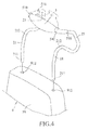
Figure 1 is a fragmentary perspective view of the first embodiment of a chair according to the present invention, illustrating a headrest assembly connected to two spaced-apart backrest frame members of a backrest; -
Figure 2 is a fragmentary side view of the first embodiment illustrating the headrest assembly; -
Figure 3 is a fragmentary rear view of the first embodiment illustrating the headrest assembly; -
Figure 4 is a fragmentary exploded perspective view of the second embodiment of a chair according to the present invention, illustrating a headrest assembly connected to a backrest by an insertion connection; -
Figure 5 is a fragmentary exploded perspective view of the third embodiment of a chair according to the present invention, illustrating a headrest assembly connected to a backrest by a sleeve connection; -
Figure 6 is a fragmentary exploded perspective view of the fourth embodiment of a chair according to the present invention, illustrating a headrest assembly and a backrest connected to each other by a fastener; -
Figure 7 is a fragmentary exploded perspective view of the fifth embodiment of a chair according to the present invention, illustrating a headrest assembly and a backrest connected to each other by a tightening ring and a fastener; -
Figure 8 is a fragmentary exploded perspective view of the sixth embodiment of a chair according to the present invention, illustrating a headrest assembly and a backrest; -
Figure 9 is a fragmentary perspective view of the seventh embodiment of a chair according to the present invention, illustrating an adjustable headrest unit of a headrest assembly; -
Figure 10 is a fragmentary perspective view of the eighth embodiment of a chair according to the present invention, illustrating a headrest assembly; -
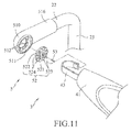
Figure 11 is a fragmentary exploded perspective view of the eighth embodiment, illustrating a connection of a head cushion and cushion couplers of the headrest assembly; -
Figure 12 is a fragmentarypartly-sectional side view of the eighth embodiment; -
Figure 13 is an exploded perspective view of the ninth embodiment of a chair according to the present invention, illustrating partially disassembling of a headrest assembly; -
Figure 14 is a fragmentary side view of the ninth embodiment, illustrating the headrest assembly having a headrest unit that is movable between upward and downward positions; -
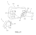
Figure 15 is a fragmentary rear view of the tenth embodiment of a chair according to the present invention, illustrating a headrest unit of a headrest assembly; -
Figure 16 is a fragmentary top view of the tenth embodiment, illustrating the headrest unit; -
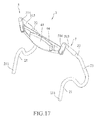
Figure 17 is a perspective view of the eleventh embodiment of a chair according to the present invention, illustrating a headrest assembly; and -
Figure 18 is a fragmentary front view of the eleventh embodiment, illustrating an adjustable headrest unit of the headrest assembly. - Before the present invention is described in greater detail, it should be noted that the same reference numerals are used to denote like elements throughout the specification.
- Referring to
Figures 1 to 3 , the first embodiment of achair 9 according to the present invention is illustrated. Thechair 9 includes a head rest assembly, a seat (not shown) on which a user can sit and abackrest 91 which allows the user to lean thereon. Thebackrest 91 has twobackrest frame members 911 that are connected to the seat and that are spaced apart from each other. Thechair 9 may be one of an office chair, a vehicle seat, a theater seat, a wheelchair seat, an assistive mobility device, an electric scooter, etc. Since the feature of this invention does not reside in the seat, which may be readily appreciated by those skilled in the art, details of the same are omitted herein for the sake of brevity. - The headrest assembly is connected to the
backrest 91. In this embodiment, the headrest assembly includes aheadrest unit 3, two spaced-apartgrip frame members 23 respectively connected to two opposite ends of theheadrest unit 3, and two spaced-apartconnection frame members 21 respectively connecting thegrip frame members 23 to thebackrest frame members 911 of thebackrest 91. In addition, the headrest assembly further includes twobridges 22, each of which bridges theheadrest unit 3 and a corresponding one of thegrip frame members 23. As a non-limiting arrangement, each of thebridges 22 and the correspondinggrip frame member 23 andconnection frame member 21 are integrally formed in one-piece. - In the first embodiment, each of the
connection frame members 21 has adistal section 211 distal from the respectivegrip frame member 23, and aproximal section 212 proximate to the respectivegrip frame member 23. As a non-limiting arrangement, thedistal section 211 of each of theconnection frame members 21 is formed as one piece with a respective one of thebackrest frame members 911. In other embodiments, thedistal section 211 of each of theconnection frame members 21 and the respective one of thebackrest frame members 911 may be fixedly or removably connected to each other in other manners, such as a welding connection, an insertion connection, a sleeved connection or a threaded connection. - In this embodiment, the
grip frame members 23 gradually extend away from each other from theheadrest unit 3 to the respectiveconnection frame members 21. Each of thegrip frame members 23 extends outwardly, rearwardly and downwardly in an oblique fashion from theheadrest unit 3 so as to be oblique relative to a firstvertical plane 81 and a second vertical plane 81' that is perpendicular to the firstvertical plane 81. The firstvertical plane 81 has opposite front and rear surface respectively facing front and rear sides of thechair 9. Specifically, each of thegrip frame members 23 forms a first angle α that is greater than 0 degrees but smaller than 30 degrees relative to the firstvertical plane 81, and a second angle β that is greater than 0 degrees but smaller than 30 degrees relative to the second vertical plane 81'. Accordingly, for example, when thechair 9 is movable and the user sitting on thechair 9 needs a helper to push thechair 9 to start moving, or the user intends to push thechair 9 to move together therewith instead of sitting thereon, the helper or the user may grasp thegrip frame members 23 with ease due to conformation of the inclination of thegrip frame members 23 with the natual extension direction of the fist eyes of the helper or user' s hands. As a non-limiting arrangement, the first angle α ranges from 10 degrees to 20 degrees relative to the firstvertical plane 81, and the second angle β ranges from 10 degrees to 20 degrees relative to the second vertical plane 81'. As another non-limiting arrangement, the first angle α ranges from 12 degrees to 15 degrees relative to the firstvertical plane 81, and the second angle β ranges from 12 degrees to 15 degrees relative to the second vertical plane 81' . - In the first embodiment, the
headrest unit 3 includes ahead cushion 41 and twocushion couplers 5. Each of thecushion couplers 5 is connected to thehead cushion 41 and a corresponding one of thebridges 22. Specifically, each of thecushion couplers 5 has afirst end 510 fixed to thehead cushion 41 and asecond end 516 distal from thefirst end 510 and connected to the corresponding one of thebridges 22. Besides, theproximal section 212 of each of theconnection frame members 21 extends rearwardly from thedistal section 211 to the corresponding one of thegrip frame members 23 in such a manner that thedistal sections 211 of theconnection frame members 21 and thefirst ends 510 of thecushion couplers 5 lie substantially in a same plane that is inclined with respect to the firstvertical plane 81. - In actual use, the
head cushion 41 supports the head of the user sitting on the seat so as to relief the stress on the user's neck. As a result, thehead cushion 41 not only provides comfort, but also reduces health issues caused by improper posture of the user's neck. In the case thechair 9 is a wheelchair, compared with handle bars of a conventional wheelchair that extend in parallel to each other, subjecting the helper or user who grips the handle bars to injury or pain due to improper posture. Since each of thegrip frame members 23 of the headrest assembly according to the first embodiment forms the first angle α and the second angle P relative to the firstvertical plane 81 and the second vertical plane 81', respectively, the helper or user can naturally grip thegrip frame members 23 in a comfortable posture when moving thechair 9 in a relatively ergonomic manner. - Besides, since the
head cushion 41 supports the user' s head and since thedistal sections 211 of theconnection frame members 21 and thefirst ends 510 of thecushion couplers 5 lie substantially in the same plane inclined with respect to the firstvertical plane 81, the user is allowed to sit on thechair 9 in a comfortable manner. -
Figure 4 illustrates the second embodiment of achair 9 according to the present invention, which has a structure generally similar to that of the first embodiment. However, in the second embodiment, thedistal section 211 of each of theconnection frame members 21 is removably assembled with thebackrest frame 91 through insertion connection. - In the second embodiment, the
chair 9 may be an office chair, a vehicle chair, a powered wheelchair or a theater chair. Thebackrest 91 has twoinsertion holes 912. Thedistal section 211 of each of theconnection frame members 21 is removably inserted into a corresponding one of the insertion holes 912. -
Figure 5 illustrates the third embodiment of achair 9 according to the present invention, which has a structure generally similar to that of the first embodiment. However, in the third embodiment, thechair 9 is a wheelchair. Each of theconnection frame members 21 is tubular in form and is sleeved detachably on the respective one of thebackrest frame members 911. - In the third embodiment, the
distal section 211 of each of theconnection frame members 21 is provided with aninsertion opening 2112, for removable insertion of the respective one of thebackrest frame members 911. In other words, thedistal section 211 of each of theconnection frame members 21 is connected to and surrounds the respective one of thebackrest frame members 911 in a detachable manner. - In the third embodiment, since the headrest assembly is removable from the
backrest 91, thebackrest frame members 911 can serve as wheelchair handle bars to allow the helper or user to move thechair assembly 9 when the headrest assembly is not required. As such, utilization of thechair 9 becomes relatively flexible and convenient to the user. When thedistal sections 211 of theconnection frame members 21 and thebackrest frame members 911 are assembled together, thegrip frame members 23 provide easy gripping and are advantageous in reducing the burdens on the user's hands when the user moves thechair 9. -
Figure 6 illustrates the fourth embodiment of achair 9 according to the present invention, which has a structure generally similar to that of the third embodiment. However, in the fourth embodiment, each of theconnection frame members 21 further has afastener 11 which is exemplified by a screw. Thefasteners 11 of theconnection frame members 21 respectively and threadedly secure thedistal sections 211 of theconnection frame members 21 to thebackrest frame members 911 so as to enhance a firm connection between the headrest assembly and thebackrest 91. -
Figure 7 illustrates the fifth embodiment of achair 9 according to the present invention, which has a structure generally similar to that of the third embodiment. However, in the fifth embodiment, each of theconnection frame members 21 further has atubular connector 214, a tighteningring 12 and afastener 11. In this embodiment, thetubular connector 214 extends from thedistal section 211 to the respective one of thebackrest frame members 911. Specifically, thetubular connector 214 has a plurality of annularly spaced-apart clampingprongs 213 surrounding the respective one of thebackrest frame members 911. The tighteningring 12 is sleeved on the clamping prongs 213. Thefastener 11 is removably connected to two opposite ends of the tighteningring 12 to tighten the tighteningring 12 and the clamping prongs 213 against the respective one of thebackrest frame members 911. -
Figure 8 illustrates the sixth embodiment of achair 9 according to the present invention, which has a structure generally similar to that of the third embodiment. However, in the sixth embodiment, each of theconnection frame members 21 further has afastener 11. Thedistal section 211 of each of theconnection frame members 21 is formed with a notched clampingring 214 and twoplates 215 extending from two opposite ends of the notched clampingring 214. Theclamping ring 214 has a C-shaped cross section, and is sleeved on the respective one of thebackrest frame members 911. Thefastener 11 is threadedly extended through theplates 215 to tighten theclamping ring 214 against the respective one of thebackrest frame members 911. -
Figure 9 illustrates the seventh embodiment of achair 9 according to the present invention, which has a structure generally similar to that of the first embodiment. However, in the seventh embodiment, thecushion couplers 5 are mounted rotatably to the respective one of thebridges 22 to permit adjustment of thehead cushion 41. Specifically, thebridges 22 respectively haveblind holes 221 substantially aligned with each other along ahorizontal line 82. Thecushion couplers 5 are respectively received in theblind holes 221 and are rotatable about thehorizontal line 82, such that thehead cushion 41 is rotatably adjustable about thehorizontal line 82. Of course, in some embodiments, thecushion couplers 5 may be respectively provided with theblind holes 221 each receiving rotatably the corresponding one of thebridges 22 so that thecushion couplers 5 are rotatable about thehorizontal line 82. - In the seventh embodiment, since the
head cushion 41 is rotatably adjustable about thehorizontal line 82, the headrest assembly is advantageous in supporting the user's head in a comfortable position at will. -
Figures 10 to 12 illustrate the eighth embodiment of a chair 9 (seeFig. 9 ) according to the present invention, which has a structure generally similar to that of the seventh embodiment. However, in the eighth embodiment, thecushion couplers 5 are connected to thehead cushion 41 in a manner different from the seventh embodiment. Since thecushion couplers 5 have the same structure, only one of thecushion couplers 5 is shown isFigures 11 and12 for the sake of brevity. - The
first end 510 of eachcushion coupler 5 has a receivinghole 511 and a plurality of annularly spaced-apartdetents 512 disposed in the receivinghole 511. In this embodiment, eachcushion coupler 5 further includes a rotatingadjuster 52 that is rotatably received in the receivinghole 511, and a threadedrod 53 that secures the rotatingadjuster 52 in the receivinghole 511. The rotatingadjuster 52 is rotatable about the threadedrod 53 in the receivinghole 511. - In this embodiment, the rotating
adjuster 52 has anannular disc 521, a cross-bar 522 that extends across theannular disc 521 and that cooperates with theannular disc 521 to form two throughholes 523, and a plurality of annularly spaced-apart retainingapertures 524 extending through theannular disc 521. The threadedrod 53 extends through the cross-bar 522. Thedetents 512 respectively and releasably extend into the retainingapertures 524 so as to limit rotation of the rotatingadjuster 52. - In the eighth embodiment, the
headrest unit 3 further includes two secure members 43 (only one is shownFigures 11 and12 ) that are respectively disposed on two opposite sides of thehead cushion 41. Eachsecure member 43 is fixed at one end to thehead cushion 41. The other end of eachsecure member 43 is engaged with the cross-bar 522 through sequentially extending through the throughholes 523 of the rotatingadjuster 52 of a corresponding one of thecushion couplers 5 and is detachably secured to thehead cushion 41. Hence, in this embodiment, thesecure members 43 are connected to thehead cushion 41 in a hook-and-loop manner. Besides, the detachable engagement between thesecure members 43 and thehead cushion 41 may be performed in a clip or adhesive connection manner. -
Figures 13 and14 illustrate the ninth embodiment of achair 9 according to the present invention, which has a structure generally similar to that of the first embodiment. However, in the ninth embodiment, theheadrest unit 3 is adjustable in an upward position and a downward position relative to the backrest 91 (seeFig. 1 ). - In the ninth embodiment, the
cushion couplers 5 are mounted removably to therespective bridges 22 and are to permit adjustment of thehead cushion 41 between the upward and downward positions. In this embodiment, each of thecushion couplers 5 has asleeve portion 513 that is detachably sleeved on the corresponding one of thebridges 22 and ajoint portion 514 that extends angularly from thesleeve portion 513 and that is connected to thehead cushion 41. In addition, thehead cushion 41 has anindentation surface 411 that is indented inwardly and that is adapted to support the user's head. - For each cushion coupler 5 (only one is shown in
Fig. 14 ), when the assembly of thecushion couplers 5 and thehead cushion 41 is disposed such that thejoint portions 514 of thecushion couplers 5 extend upwardly relative to thesleeve portions 513 when thesleeve portions 513 are respectively sleeved on thebridges 22, thehead cushion 41 is disposed upwardly relative tosleeve portions 513 and theindentation surface 411 faces upward. As such, theheadrest unit 3 is disposed in the upward position. By flipping the assembly of thecushion couplers 5 and thehead cushion 41 upside-down such that thejoint portions 514 extend downwardly relative to thesleeve portions 513 and thesleeve portions 513 are respectively sleeved on thebridges 22, thehead cushion 41 is disposed downwardly relative to thesleeve portions 513 and theindentation surface 411 faces downwardly. As such, theheadrest unit 3 is disposed in the downward position. - By virtue of the
sleeve portions 513 being detachably sleeved on thebridges 22, theheadrest unit 3 is adjustable between the upward and downward positions. In such arrangement, theindentation surface 411 of thehead cushion 41 is adjustable to face upwardly or downwardly in accordance with the user's requirement. -
Figures 15 and16 illustrate the tenth embodiment of a chair 9 (seeFig. 1 ) according to the present invention, which has a structure generally similar to that of the ninth embodiment. - However, in the tenth embodiment, the
joint portion 514 of eachcushion coupler 5 has two spaced-apart connection holes 515 that are aligned with each other in a top-down direction. In addition, theheadrest unit 3 further includes two spaced-apart secure member units. Each of the secure member units includes three secure members 43' that are separately aligned with each other in the top-down direction and that are disposed on thehead cushion 41 to face the first vertical plane 81 (seeFig. 2 ) . In this embodiment, any two secure members 43' of each secure member unit are fixed at first ends to thehead cushion 41 and respectively have second ends that are respectively opposite to the first ends, that extend through the connection holes 515 of the corresponding one of thecushion couplers 5 and that are detachably secured to thehead cushion 41. In this embodiment, the second ends of the secure members 43' are connected to thehead cushion 41 in a hook-and-loop manner. However, such is not limited to this disclosure. For example, any two secure members 43' can extend through the connection holes 515 to secure thehead cushion 41 to thecorresponding cushion coupler 5 in a clip or adhesive connection manner. - In actual use, since each
cushion coupler 5 is detachably connected to thehead cushion 41, thehead cushion 41 can first be adjusted to a proper height relative to thebackrest 91, and then be secured at the proper height by extending two opposite secure members 43' of each secure member unit through the connection holes 515 of thecorresponding cushion coupler 5. As a result, the user can adjust the height of theheadrest unit 3 relative to thebackrest 91 as desired. It should be noted herein that the numbers of the connection holes 515 and the secure members 43' are not limited to this disclosure. -
Figures 17 and18 illustrate the eleventh embodiment of a chair 9 (seeFig. 1 ) according to the present invention, which has a structure generally similar to that of the ninth embodiment. However, in the eleventh embodiment, theheadrest unit 3 further includes a mountingplate 44 on which thehead cushion 41 is mounted. In this embodiment, for each of thecushion couplers 5, thesleeve portion 513 is detachably sleeved on the corresponding one of thebridges 22, and thejoint portion 514 is pivotally connected between thesleeve portion 513 and a corresponding one of two opposite sides of the mountingplate 44. - In actual use, the
head cushion 41 and the mountingplate 44 are adjustable together in the top-down manner (shown inFig. 18 ) according to the user's requirement by virtue of the pivotable connection between thejoint portion 514 of eachcushion couplers 5 and each of thesleeve portion 513 and the corresponding side of the mountingplate 44. Since the feature of thechair 9 does not reside in the configurations of the mountingplate 44, and thejoint portion 514 andsleeve portion 513 of eachcushion coupler 5, which may be readily changed and adjusted by those skilled in the art, details of the same are omitted herein for the sake of brevity. - To sum up, by virtue of the headrest assembly that is feasible to be connected to the
backrests 91 of various chairs, theheadrest unit 3 not only can be adjustable in height relative to thebackrest 91 according the user's requirement, but also may relax the burden of the user's neck to provide improved comfortableness. Moreover, since eachgrip frame members 23 of the headrest assembly forms the first angle α and the second angle β respectively relative to the firstvertical plane 81 and the second vertical plane 81' , the helper or user can naturally grip thegrip frame members 23 in a comfortable posture when the need arises.
Claims (13)
- A headrest assembly for connecting a backrest (91) of a chair (9), the headrest assembly characterized by:a headrest unit (3);two spaced-apart grip frame members (23) respectively connected to two opposite ends of said headrest unit (3); andtwo spaced-apart connection frame members (21) respectively connected to said grip frame members (23) for connection with the backrest (91);wherein said grip frame members (23) gradually extend away from each other from said headrest unit (3) to said connection frame members (21), respectively, each of said grip frame members (23) extending obliquely, rearwardly and downwardly from said headrest unit (3) in a manner of being oblique relative to a first vertical plane (81) that has opposite front and rear surfaces respectively facing front and rear sides of the chair (9).
- The headrest assembly as claimed in Claim 1, characterized in that each of said grip frame members (23) forms a first angle (α) that is greater than 0 degrees but smaller than 30 degrees relative to the first vertical plane (81), and a second angle (β) that is greater than 0 degrees but smaller than 30 degrees relative to a second vertical plane (81') perpendicular to the first vertical plane (81).
- The headrest assembly as claimed in claim 1, further characterized by two bridges (22), each of which bridges said headrest unit (3) and a corresponding one of said grip frame members (23), said headrest unit (3) including a head cushion (41), and two cushion couplers (5), each of which is connected to said head cushion (41) and a corresponding one of said bridges (22).
- The headrest assembly as claimed in claim 3, characterized in that each of said cushion couplers (5) has a first end (510) fixed to said head cushion (41) and a second end (516) distal from said first end (510) and connected to the corresponding one of said bridges (22).
- The headrest assembly as claimed in claim 3, characterized in that said cushion couplers (5) are mounted adjustably and respectively to said bridges (22) and are rotatable to permit adjustment of said head cushion (41).
- The headrest assembly as claimed in claim 3, characterized in that said cushion couplers (5) are mounted detachably and respectively to said bridges (22) and are movable upward and downward to permit adjustment of said head cushion (41).
- The headrest assembly as claimed in Claim 4, characterized in that each of said connection frame members (21) has a distal section (211) distal from the corresponding one of said grip frame members (23), and a proximal section (212) proximate to the corresponding one of said grip frame members (23), said proximal section (212) extending rearwardly from said distal section (211) to the corresponding one of said grip frame members (23) in a manner that said distal sections (211) of said connection frame members (23) and said first ends (510) of said cushion couplers lie substantially in a same plane that is inclined with respect to said first vertical plane (81).
- A chair (9) characterized by:a backrest (91) having two backrest frame members (911);a headrest unit (3);two spaced-apart grip frame members (23) respectively connected to two opposite ends of said headrest unit (3); andtwo spaced-apart connection frame members (21) respectively connecting said grip frame members (23) to said backrest frame members (911);wherein said grip frame members (23) gradually extend away from each other from said headrest unit (3) to said connection frame members (21), respectively, each of said grip frame members (23) extending obliquely, rearwardly and downwardly from said headrest unit (3) in a manner of being oblique relative to a first vertical plane (81) that has opposite front and rear surfaces respectively facing front and rear sides of the chair assembly (9).
- The chair (9) as claimed as Claim 8, characterized in that each of said connection frame members (21) is formed as one piece with the respective one of said backrest frame members (911).
- The chair (9) as claimed as Claim 8, characterized in that each of said connection frame members (21) is tubular and is sleeved detachably on the respective one of said backrest frame members (911).
- The chair (9) as claimed as Claim 10, characterized in that each of said connection frame members (21) has a tubular connector (214), a tightening ring (12) and a fastener (11), said tubular connector (214) having a plurality of annularly spaced-apart clamping prongs (213) that surround the respective one of said backrest frame members (911), said tightening ring (12) being sleeved on said clamping prongs (213), said fastener (11) being removably connected to two opposite ends of said tightening ring (12) to tighten said tightening ring (12) and said clamping prongs (213) against the respective one of said backrest frame members (911).
- The chair (9) as claimed as Claim 9, characterized in that said backrest (91) has two insertion holes (912), said connection frame members (21) being inserted respectively into said insertion holes (912).
- The chair (9) as claimed in Claim 9, which is a wheelchair.
Applications Claiming Priority (1)
| Application Number | Priority Date | Filing Date | Title |
|---|---|---|---|
| TW102130041A TW201507664A (en) | 2013-08-22 | 2013-08-22 | Universal headrest device for chair |
Publications (1)
| Publication Number | Publication Date |
|---|---|
| EP2839762A1 true EP2839762A1 (en) | 2015-02-25 |
Family
ID=51398494
Family Applications (1)
| Application Number | Title | Priority Date | Filing Date |
|---|---|---|---|
| EP14181835.1A Withdrawn EP2839762A1 (en) | 2013-08-22 | 2014-08-21 | Headrest assembly and chair assembly including the same |
Country Status (6)
| Country | Link |
|---|---|
| US (1) | US20150054326A1 (en) |
| EP (1) | EP2839762A1 (en) |
| JP (1) | JP2015039633A (en) |
| CN (1) | CN104414238A (en) |
| AU (1) | AU2014215981A1 (en) |
| TW (1) | TW201507664A (en) |
Cited By (1)
| Publication number | Priority date | Publication date | Assignee | Title |
|---|---|---|---|---|
| EP3818910A1 (en) * | 2019-11-06 | 2021-05-12 | Guangzhou Huashi Furniture Manufacturing Co., Ltd. | A head restraint |
Families Citing this family (1)
| Publication number | Priority date | Publication date | Assignee | Title |
|---|---|---|---|---|
| CN109090879B (en) * | 2018-10-11 | 2024-03-15 | 福建荣荣新材料股份有限公司 | Integrally knitted and formed wearing sleeve type chair surface and chair with same |
Citations (5)
| Publication number | Priority date | Publication date | Assignee | Title |
|---|---|---|---|---|
| US2172797A (en) * | 1936-02-03 | 1939-09-12 | Dorothy E Jones | Adjustable head support |
| EP0813991A1 (en) * | 1995-09-18 | 1997-12-29 | Fabricacion Asientos Vehiculos Industriales, S.A. (Fainsa) | Seat for public transport vehicles |
| DE19908592C1 (en) * | 1999-02-27 | 2000-11-23 | Hermann Himmelmann | Office chair for a computer terminal workstation has a tube which is bent from the rear of the seat into structures to form the armrests and backrest for effective muscular and spinal support |
| JP2001095854A (en) * | 1999-10-01 | 2001-04-10 | Honda Motor Co Ltd | Wheelchair |
| WO2011005231A1 (en) * | 2009-07-06 | 2011-01-13 | Burosit Buro Donanimlari Sanayi Ve Ticaret Anonim Sirketi | Sitting apparatus providing body ergonomy |
Family Cites Families (16)
| Publication number | Priority date | Publication date | Assignee | Title |
|---|---|---|---|---|
| US3205005A (en) * | 1964-08-10 | 1965-09-07 | Brown Ray | Energy-absorbing headrest for motor vehicle seats |
| US3371961A (en) * | 1967-01-30 | 1968-03-05 | American Safety Equip | Fitting for mounting headrests |
| US5927814A (en) * | 1998-06-18 | 1999-07-27 | Tachi-S Co., Ltd. | Headrest |
| TW368857U (en) * | 1998-08-03 | 1999-09-01 | Karma Medical Prod Co Ltd | Wheel chair structure |
| JP4280950B2 (en) * | 1999-08-09 | 2009-06-17 | アイシン精機株式会社 | Headrest device |
| DE10161587A1 (en) * | 2001-12-14 | 2003-06-26 | Dauphin Friedrich W Gmbh | chair |
| US6866288B2 (en) * | 2002-04-10 | 2005-03-15 | Willis Martin | Convertible wheelchair and separate lift module for connecting to and elevating the wheelchair |
| US7032974B1 (en) * | 2003-08-06 | 2006-04-25 | Karla Klumpp Berger | Headrest assembly |
| US7360781B2 (en) * | 2004-01-23 | 2008-04-22 | Sunrise Medical Hhg Inc. | Foldable wheelchair and axle plate therefor |
| US7338130B2 (en) * | 2004-12-06 | 2008-03-04 | Honda Motor Co., Ltd. | Locking headrest assembly |
| DE102005001866B4 (en) * | 2005-01-14 | 2009-01-02 | Aquatec Gmbh | Footrest for wheelchairs or the like |
| CN201264546Y (en) * | 2008-07-17 | 2009-07-01 | 史平华 | Seat headrest regulating mechanism with four-direction regulation function and rotation function |
| US20120025582A1 (en) * | 2009-04-23 | 2012-02-02 | Lear Corporation | Seat assembly having an adjustable head restraint assembly |
| US20100289315A1 (en) * | 2009-05-13 | 2010-11-18 | Steve Jackson | Apparatus for portable cushions for head and neck support of a passenger in a vehicle |
| CN201754990U (en) * | 2010-06-25 | 2011-03-09 | 上海电机学院 | Portable health-care back cushion |
| CN203468069U (en) * | 2013-07-19 | 2014-03-12 | 浙江大丰实业股份有限公司 | Leisure chair with back cushion |
-
2013
- 2013-08-22 TW TW102130041A patent/TW201507664A/en unknown
-
2014
- 2014-08-04 CN CN201410378554.5A patent/CN104414238A/en active Pending
- 2014-08-20 JP JP2014167268A patent/JP2015039633A/en active Pending
- 2014-08-21 EP EP14181835.1A patent/EP2839762A1/en not_active Withdrawn
- 2014-08-21 AU AU2014215981A patent/AU2014215981A1/en not_active Abandoned
- 2014-08-21 US US14/464,778 patent/US20150054326A1/en not_active Abandoned
Patent Citations (5)
| Publication number | Priority date | Publication date | Assignee | Title |
|---|---|---|---|---|
| US2172797A (en) * | 1936-02-03 | 1939-09-12 | Dorothy E Jones | Adjustable head support |
| EP0813991A1 (en) * | 1995-09-18 | 1997-12-29 | Fabricacion Asientos Vehiculos Industriales, S.A. (Fainsa) | Seat for public transport vehicles |
| DE19908592C1 (en) * | 1999-02-27 | 2000-11-23 | Hermann Himmelmann | Office chair for a computer terminal workstation has a tube which is bent from the rear of the seat into structures to form the armrests and backrest for effective muscular and spinal support |
| JP2001095854A (en) * | 1999-10-01 | 2001-04-10 | Honda Motor Co Ltd | Wheelchair |
| WO2011005231A1 (en) * | 2009-07-06 | 2011-01-13 | Burosit Buro Donanimlari Sanayi Ve Ticaret Anonim Sirketi | Sitting apparatus providing body ergonomy |
Cited By (1)
| Publication number | Priority date | Publication date | Assignee | Title |
|---|---|---|---|---|
| EP3818910A1 (en) * | 2019-11-06 | 2021-05-12 | Guangzhou Huashi Furniture Manufacturing Co., Ltd. | A head restraint |
Also Published As
| Publication number | Publication date |
|---|---|
| AU2014215981A1 (en) | 2015-03-12 |
| US20150054326A1 (en) | 2015-02-26 |
| JP2015039633A (en) | 2015-03-02 |
| CN104414238A (en) | 2015-03-18 |
| TW201507664A (en) | 2015-03-01 |
Similar Documents
| Publication | Publication Date | Title |
|---|---|---|
| US20080067850A1 (en) | Backrest for a chair | |
| US8376463B2 (en) | User adjustable wheelchair backrest mounting hardware | |
| US20130226053A1 (en) | Adjustable Postural Support Device | |
| JP4817833B2 (en) | Adjustable headrest for wheelchair | |
| EP2839762A1 (en) | Headrest assembly and chair assembly including the same | |
| US20130320746A1 (en) | Slouch Correction Device and Method | |
| KR101167816B1 (en) | Backrest Chair | |
| JP2013165955A (en) | Safety chair for reverse-sitting | |
| JP5479649B1 (en) | Wheelchair support | |
| KR101605830B1 (en) | A chair auxiliary apparatus for correcting posture | |
| JP2009195262A (en) | Seat with headrest | |
| JP3223462U (en) | Seating aid | |
| KR200324966Y1 (en) | Headrest for chair | |
| JP6040509B2 (en) | Portable backrest | |
| KR200411162Y1 (en) | A lumbar supporting device for chair | |
| KR102182578B1 (en) | Detachable chest supporter for chair | |
| EP3673767B1 (en) | A portable body support device | |
| CN220181093U (en) | Backrest adjusting mechanism for aviation seat | |
| KR102016009B1 (en) | Neck support to maintain posture | |
| CN210077123U (en) | Reset correction chair back and chair | |
| CN209814293U (en) | Assist armrest for aircraft seat | |
| TW201733496A (en) | Lower-back supporting device of chair | |
| TWM473759U (en) | Chair | |
| KR20210092473A (en) | Removable body correction rod | |
| WO2012005528A2 (en) | Apparatus for adjusting the supporter of a posture correction chair |
Legal Events
| Date | Code | Title | Description |
|---|---|---|---|
| PUAI | Public reference made under article 153(3) epc to a published international application that has entered the european phase |
Free format text: ORIGINAL CODE: 0009012 |
|
| 17P | Request for examination filed |
Effective date: 20140821 |
|
| AK | Designated contracting states |
Kind code of ref document: A1 Designated state(s): AL AT BE BG CH CY CZ DE DK EE ES FI FR GB GR HR HU IE IS IT LI LT LU LV MC MK MT NL NO PL PT RO RS SE SI SK SM TR |
|
| AX | Request for extension of the european patent |
Extension state: BA ME |
|
| R17P | Request for examination filed (corrected) |
Effective date: 20150825 |
|
| RBV | Designated contracting states (corrected) |
Designated state(s): AL AT BE BG CH CY CZ DE DK EE ES FI FR GB GR HR HU IE IS IT LI LT LU LV MC MK MT NL NO PL PT RO RS SE SI SK SM TR |
|
| GRAP | Despatch of communication of intention to grant a patent |
Free format text: ORIGINAL CODE: EPIDOSNIGR1 |
|
| INTG | Intention to grant announced |
Effective date: 20170323 |
|
| STAA | Information on the status of an ep patent application or granted ep patent |
Free format text: STATUS: THE APPLICATION IS DEEMED TO BE WITHDRAWN |
|
| 18D | Application deemed to be withdrawn |
Effective date: 20170803 |