EP2839210B1 - Heat dissipating device and illuminating device with the heat dissipating device - Google Patents
Heat dissipating device and illuminating device with the heat dissipating device Download PDFInfo
- Publication number
- EP2839210B1 EP2839210B1 EP13716315.0A EP13716315A EP2839210B1 EP 2839210 B1 EP2839210 B1 EP 2839210B1 EP 13716315 A EP13716315 A EP 13716315A EP 2839210 B1 EP2839210 B1 EP 2839210B1
- Authority
- EP
- European Patent Office
- Prior art keywords
- cup
- heat sink
- heat dissipating
- dissipating device
- heat
- Prior art date
- Legal status (The legal status is an assumption and is not a legal conclusion. Google has not performed a legal analysis and makes no representation as to the accuracy of the status listed.)
- Active
Links
Images


Classifications
-
- F—MECHANICAL ENGINEERING; LIGHTING; HEATING; WEAPONS; BLASTING
- F21—LIGHTING
- F21V—FUNCTIONAL FEATURES OR DETAILS OF LIGHTING DEVICES OR SYSTEMS THEREOF; STRUCTURAL COMBINATIONS OF LIGHTING DEVICES WITH OTHER ARTICLES, NOT OTHERWISE PROVIDED FOR
- F21V29/00—Protecting lighting devices from thermal damage; Cooling or heating arrangements specially adapted for lighting devices or systems
- F21V29/50—Cooling arrangements
- F21V29/70—Cooling arrangements characterised by passive heat-dissipating elements, e.g. heat-sinks
- F21V29/71—Cooling arrangements characterised by passive heat-dissipating elements, e.g. heat-sinks using a combination of separate elements interconnected by heat-conducting means, e.g. with heat pipes or thermally conductive bars between separate heat-sink elements
- F21V29/713—Cooling arrangements characterised by passive heat-dissipating elements, e.g. heat-sinks using a combination of separate elements interconnected by heat-conducting means, e.g. with heat pipes or thermally conductive bars between separate heat-sink elements in direct thermal and mechanical contact of each other to form a single system
-
- F—MECHANICAL ENGINEERING; LIGHTING; HEATING; WEAPONS; BLASTING
- F21—LIGHTING
- F21V—FUNCTIONAL FEATURES OR DETAILS OF LIGHTING DEVICES OR SYSTEMS THEREOF; STRUCTURAL COMBINATIONS OF LIGHTING DEVICES WITH OTHER ARTICLES, NOT OTHERWISE PROVIDED FOR
- F21V23/00—Arrangement of electric circuit elements in or on lighting devices
- F21V23/003—Arrangement of electric circuit elements in or on lighting devices the elements being electronics drivers or controllers for operating the light source, e.g. for a LED array
-
- F—MECHANICAL ENGINEERING; LIGHTING; HEATING; WEAPONS; BLASTING
- F21—LIGHTING
- F21V—FUNCTIONAL FEATURES OR DETAILS OF LIGHTING DEVICES OR SYSTEMS THEREOF; STRUCTURAL COMBINATIONS OF LIGHTING DEVICES WITH OTHER ARTICLES, NOT OTHERWISE PROVIDED FOR
- F21V29/00—Protecting lighting devices from thermal damage; Cooling or heating arrangements specially adapted for lighting devices or systems
- F21V29/50—Cooling arrangements
- F21V29/70—Cooling arrangements characterised by passive heat-dissipating elements, e.g. heat-sinks
- F21V29/74—Cooling arrangements characterised by passive heat-dissipating elements, e.g. heat-sinks with fins or blades
- F21V29/77—Cooling arrangements characterised by passive heat-dissipating elements, e.g. heat-sinks with fins or blades with essentially identical diverging planar fins or blades, e.g. with fan-like or star-like cross-section
- F21V29/773—Cooling arrangements characterised by passive heat-dissipating elements, e.g. heat-sinks with fins or blades with essentially identical diverging planar fins or blades, e.g. with fan-like or star-like cross-section the planes containing the fins or blades having the direction of the light emitting axis
-
- F—MECHANICAL ENGINEERING; LIGHTING; HEATING; WEAPONS; BLASTING
- F21—LIGHTING
- F21V—FUNCTIONAL FEATURES OR DETAILS OF LIGHTING DEVICES OR SYSTEMS THEREOF; STRUCTURAL COMBINATIONS OF LIGHTING DEVICES WITH OTHER ARTICLES, NOT OTHERWISE PROVIDED FOR
- F21V29/00—Protecting lighting devices from thermal damage; Cooling or heating arrangements specially adapted for lighting devices or systems
- F21V29/85—Protecting lighting devices from thermal damage; Cooling or heating arrangements specially adapted for lighting devices or systems characterised by the material
- F21V29/87—Organic material, e.g. filled polymer composites; Thermo-conductive additives or coatings therefor
-
- F—MECHANICAL ENGINEERING; LIGHTING; HEATING; WEAPONS; BLASTING
- F21—LIGHTING
- F21V—FUNCTIONAL FEATURES OR DETAILS OF LIGHTING DEVICES OR SYSTEMS THEREOF; STRUCTURAL COMBINATIONS OF LIGHTING DEVICES WITH OTHER ARTICLES, NOT OTHERWISE PROVIDED FOR
- F21V29/00—Protecting lighting devices from thermal damage; Cooling or heating arrangements specially adapted for lighting devices or systems
- F21V29/85—Protecting lighting devices from thermal damage; Cooling or heating arrangements specially adapted for lighting devices or systems characterised by the material
- F21V29/89—Metals
Definitions
- the present invention relates to a heat dissipating device and an illuminating device with the heat dissipating device.
- the heat dissipating device can be made from materials having different thermal conductivities. For instance, a bulb for accommodating a light engine and a driver can be made from a thermal conductive plastic, and metal fins are inserted into inside of the bulb for heat dissipation.
- a heat dissipating device has a cup body for accommodating a light engine, and a bottom surface of the cup body or the whole cup body is made of a metal. On an opposite side of the cup body, an accommodating cavity made from a thermal conductive plastic and extending from a bottom surface thereof is formed, for accommodating a driver that should be in electrical insulation from a light engine. As there is only one metal bottom plate or cup body having good thermal conductivity, only limited heat dissipating effect can be achieved.
- EP2320133A2 discloses a LED light unit comprising an outer case and a heat radiating body. A space is partitioned between the outer case and the outermost end of the heat radiating body.
- one object of the present invention lies in providing a heat dissipating device for illuminating device.
- the heat dissipating device has a simple structure, good heat dissipating performance and at least partially has electrically insulating property.
- the heat dissipating device for illuminating device in accordance with the present invention comprises a first heat sink, characterized in that the first heat sink comprises a first cup and a second cup superposing on each other, wherein the first heat sink is made from a first thermal conductive material, the heat dissipating device further comprises a second heat sink made from an insulative second thermal conductive material, the first cup and the second cup are partially covered by the second heat sink, respectively, and the first thermal conductive material has a higher thermal conductivity than the second thermal conductive material.
- the concept of the present invention lies in manufacturing the heat dissipating device utilizing materials having a high thermal conductivity, as much as is possible, as main body, while assuring electrical insulation with part of electronic components provided in the heat dissipating device or electronic components provided near to the heat dissipating device in the illuminating device, so as to realize good heat dissipating effect.
- the heat dissipating device in accordance with the present invention is made from first and second thermal conductive materials, wherein the first thermal conductive material has a better thermal conductivity than the second thermal conductive material, while the second thermal conductive material has characteristics of electrical insulation.
- the first thermal conductive material is provided with a big area in the heat dissipating device to form the main part of the heat dissipating device, i.e. main heat dissipating component.
- the first cup and the second cup are partially covered by the second heat sink according to the present invention, that is, the second heat sink that has the electrical insulating effect and can conduct heat partially envelops the first heat sink.
- the heat dissipating device manufactured in such a manner also can be called "hybrid heat-sink".
- the first cup and the second cup superpose on each other such that the first heat sink having a cross section with an H-shaped profile is formed.
- the first cup and the second cup abut against each other through respective end surfaces thereof so as to form the first heat sink, moreover, open ends of the first and second cups face opposite directions to form, for instance, an upper open end and a low open end of the first heat sink.
- the first heat sink formed in such a manner can accommodate two components to dissipate heat in the first and the second cups, respectively, so as to dissipate heat therefrom.
- the second heat sink has a body, and the first cup and the second cup are at least partially covered by the body, respectively.
- the body for instance, can cover inner circumferential walls and/or outer circumferential walls and/or inner surfaces of respective bases of the first cup and the second cup, so as to form a profile matching the shape of the first heat sink and to be in good thermal contact with the first heat sink.
- the outer circumferential walls of the first cup and the second cup are covered by the body.
- the insulating second heat sink only covers the outer circumferential walls of the first heat sink, and the second heat sink is not on the inner circumferential walls of the first heat sink, i.e. the inner circumferential walls of the first and second cups, and the inner surfaces of the bases facing respective open ends.
- components to dissipate heat accommodated in the first and second cups can be in direct, quick and highly effective thermal contact with the first heat sink.
- the heat dissipating device can be, through the second heat sink, in electrically-insulating thermal contact with neighboring components arranged in the illuminating device.
- the inner circumferential walls and the outer circumferential walls of the first cup and the second cup are imbedded into the body.
- the second heat sink by means of the second heat sink, at least part of the first heat sink can be assured to be in electrically-insulating thermal contact with the components to dissipate heat accommodated in the first cup and the second cup.
- the second heat sink covers the inner surface of the base of the first cup.
- the second heat sink does not cover the inner surface of the base of the second cup.
- the electrically insulating second heat sink preferably can cover the inner surface of the base of the first cup in a form of extra layer, and the inner surface faces the open end of the first cup.
- the inner surface of the base of the second cup faces the open end of the second cup, and components to dissipate heat and requiring no electrically insulating protection can be preferably directly mounted on and is in thermal contact with this inner surface, and also can be arranged in the second cup in other manners.
- components to dissipate heat can be quickly and effectively cooled.
- the first cup and the second cup are made of a metal. Since metal has a higher thermal conductivity than rubber, plastic or other materials, aluminum, copper and other metals having good thermal conductivity can be chosen herein to manufacture the first cup and the second cup.
- the first cup and the second cup are made in one piece.
- the first cup and the second cup are of a metal material, they can be made in one piece to become the first heat sink utilizing various suitable processes, which simplifies the manufacturing process and reduces the cost.
- the superposing regions of the first and second cups, i.e. bases of the first and second cups are also made in one piece, the thermal conductive effect between the first cup and the second cup is enhanced.
- the first cup and the second cup are made through a stamping process, respectively.
- large-scale production of such cups can be realized through the stamping process.
- the first cup and the second cup are joined by means of thermal conductive glue, by means of which the bases of the first cup and the second cup closely abut against each other as much as is possible and can be in fixed connection. Therefore, the thermal conducting effect between the first cup and the second cup also can be improved.
- the second heat sink further comprises a plurality of fins formed on an outer circumferential wall of the body.
- Heat dissipating area of the heat dissipating device can be increased by forming extra fins, for instance, heat transferred to the second heat sink radiates to surrounding environment in a heat radiation mode.
- the plurality of fins and the body are made in one piece.
- the fins and the second heat sink can be directly made in one piece, the manufacturing process is simplified.
- the fins are configured as insert-type fins or other parts having suitable structures for arrangement on the outer circumferential wall of the body.
- the first heat sink and the second heat sink are made together through an injection molding process, by means of which the second heat sink can be sprayed on the first heat sink and is enabled to have a profile matching the first heat sink.
- the second heat sink is made from a thermal conductive plastic.
- the second heat sink can have dual properties of thermal conduction and insulation.
- the present invention further relates to an illuminating device comprising a driver, a light engine, and the heat dissipating device above.
- the driver is arranged in the first cup and the light engine is arranged in the second cup.
- the driver and the light engine are accommodated by the first and the second cups so as to save the structure space inside the illuminating device.
- the heat dissipating device also can advantageously transmit outwardly heat generated by the driver and the light engine.
- the first cup and the driver can be in electrically-insulating thermal contact so as to dissipate heat while meeting requirements of electrics security.
- Fig. 1 shows a first embodiment of a heat dissipating device 100 in accordance with the present invention.
- the heat dissipating device 100 for an illuminating device (not shown) comprises a first heat sink 1 and a second heat sink 4.
- the first heat sink 1 and the second heat sink 4 are made from two materials having different thermal conductivities, respectively.
- the first heat sink 1 having good thermal conductivity is configured as a first cup 2 and a second cup 3 that are arranged opposite to each other, wherein open ends of the two cups face opposite directions for accommodating the components to dissipate heat, respectively; and another material having a slightly low thermal conductivity, preferably having electrically insulating characteristic, is used to manufacture the second heat sink 4.
- the first cup 2 and the second cup 3 herein are particularly partially covered by the second heat sink 4 such that the first heat sink 1 having a high thermal conductivity is assembled at a big area with the electrically insulating second heat sink 4 for use, thereby the heat dissipating device 100 has an ideal heat dissipating effect and the first heat sink 1 can be assured to electrically insulate from components to dissipate heat mounted therein or components surrounding the heat dissipating device 100 in the illuminating device.
- the first cup 2 and the second cup 3 are configured as two independent parts and directly closely abut against each other through respective bases thereof.
- the first cup 2 and the second cup 3 are made from a metal having a high thermal conductivity, and the metal is, for instance, aluminum, copper or other suitable metal materials. Based on properties of metal material, the first cup 2 and the second cup 3 can be manufactured through a stamping process in production for improving the productive efficiency and reducing the manufacturing cost.
- a thermal conductive plastic is preferably chosen as a thermal conductive material having electrically insulting performance to manufacture the second heat sink 4.
- a body 5 covering the second heat sink 4 can be formed on at least an outer circumferential wall 7 of the first heat sink 1 through an injection molding process, as a result, the body 5 has a shape matching an outer profile of the first heat sink 1.
- a plurality of additional fins 10 are formed on an outer circumferential wall of the body 5 for increasing the thermal contact area between the heat dissipating device 100 and the external environment.
- the fins 10 can be advantageously formed on the body 5 in one piece.
- the fins 10 and the body 5 are formed independently, and mechanical linking structures such as slot and connecting piece are formed on the fins 10 or the body 5 to assemble the fins 10 and the body 5 together.
- first cup 2 and the second cup 3 can be advantageously in fixed thermal-conductive connection through bases thereof utilizing, for instance, thermal conductive glue.
- Fig. 2 is a cross-section diagram of a second embodiment of a heat dissipating device.
- the first cup 2 and the second cup 3 are made into an H-shaped first heat sink 1 in an integral manner, and the first heat sink 1 is covered by the body 5 of the second heat sink 4 through an insert-injection process or a similar process.
- a hybrid heat dissipating device structure characterized by "outer plastic and inner metal" as shown in the cross-section diagram is accomplished.
- the second heat sink 4 made from a thermal conductive plastic herein is an outer housing of the heat dissipating device 100, and then the heat dissipating device 100 can electrically insulate from other components arranged surrounding or near to the heat dissipating device 100 in the illuminating device.
- Fig. 3 is a cross-section diagram of a third embodiment of a heat dissipating device 100 in accordance with the present invention.
- the third embodiment is different from the embodiment shown in Fig. 2 in that circumferential walls of the first cup 2 and the second 3 are completely imbedded into the body 5 made from a thermal conductive plastic, i.e. the thermal conductive plastic completely covers the inner circumferential walls 6 and the outer circumferential walls 7 of the first heat sink 1.
- an electrically-insulating thermal contact can be assured between the inner circumferential walls 6 of the first cup 2 and the second cup 3 and part of components to dissipate heat accommodated therein, and bases of the first cup 2 and the second cup 3 are in direct thermal contact with another part of the components to dissipate heat.
- the heat dissipating device 100 having such structure can be in safe and highly-effective pertinent thermal contact with respective components to dissipate heat.
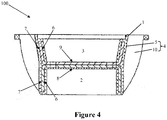
- Fig. 4 is a cross-section diagram of a fourth embodiment of a heat dissipating device in accordance with the present invention.
- the fourth embodiment is different from the embodiment shown in Fig. 3 in that apart from the inner circumferential walls 6 and the outer circumferential walls 7 of the first heat sink 1 being completely imbedded into the body 5, a bottom surface of the base of the first cup 2, i.e. an inner surface 8 facing the open end, is also imbedded into the body 5, and an inner surface 9 of the base of the second cup 3 is not covered by the body 5.
- the electrically insulating first cup 2 is particularly suitable to accommodate components such as driver or the like, and therefore, there is no need to provide an additional prior insulating housing for the driver accommodated therein.
Landscapes
- Engineering & Computer Science (AREA)
- General Engineering & Computer Science (AREA)
- Microelectronics & Electronic Packaging (AREA)
- Arrangement Of Elements, Cooling, Sealing, Or The Like Of Lighting Devices (AREA)
Description
- The present invention relates to a heat dissipating device and an illuminating device with the heat dissipating device.
- High-power light source, especially LED light source, is widely used in modern illuminating devices, as a result, how to improve the heat dissipating effect of the illuminating device has become an important research direction. In order to protect electronic parts inside the illuminating device, the electrically insulating performance of a heat sink in relation to the electronic parts also should be taken into consideration when a heat sink having metal parts is designed. In the prior art, the heat dissipating device can be made from materials having different thermal conductivities. For instance, a bulb for accommodating a light engine and a driver can be made from a thermal conductive plastic, and metal fins are inserted into inside of the bulb for heat dissipation. However, the heat dissipating function of such heat dissipating device is not ideal, and too much cost and assembling are needed for mounting the fins. In one product of the same type of PHILIPS, a heat dissipating device has a cup body for accommodating a light engine, and a bottom surface of the cup body or the whole cup body is made of a metal. On an opposite side of the cup body, an accommodating cavity made from a thermal conductive plastic and extending from a bottom surface thereof is formed, for accommodating a driver that should be in electrical insulation from a light engine. As there is only one metal bottom plate or cup body having good thermal conductivity, only limited heat dissipating effect can be achieved.
- An earlier patent application
EP2320133A2 discloses a LED light unit comprising an outer case and a heat radiating body. A space is partitioned between the outer case and the outermost end of the heat radiating body. - Therefore, one object of the present invention lies in providing a heat dissipating device for illuminating device. The heat dissipating device has a simple structure, good heat dissipating performance and at least partially has electrically insulating property.
- The heat dissipating device for illuminating device in accordance with the present invention comprises a first heat sink, characterized in that the first heat sink comprises a first cup and a second cup superposing on each other, wherein the first heat sink is made from a first thermal conductive material, the heat dissipating device further comprises a second heat sink made from an insulative second thermal conductive material, the first cup and the second cup are partially covered by the second heat sink, respectively, and the first thermal conductive material has a higher thermal conductivity than the second thermal conductive material.
- The concept of the present invention lies in manufacturing the heat dissipating device utilizing materials having a high thermal conductivity, as much as is possible, as main body, while assuring electrical insulation with part of electronic components provided in the heat dissipating device or electronic components provided near to the heat dissipating device in the illuminating device, so as to realize good heat dissipating effect. Specifically, the heat dissipating device in accordance with the present invention is made from first and second thermal conductive materials, wherein the first thermal conductive material has a better thermal conductivity than the second thermal conductive material, while the second thermal conductive material has characteristics of electrical insulation. In order to enable such heat dissipating device made from multiple materials to have good thermal conductivity, the first thermal conductive material is provided with a big area in the heat dissipating device to form the main part of the heat dissipating device, i.e. main heat dissipating component. Moreover, in order to give attention to the characteristics of electrical insulation at the same time, the first cup and the second cup are partially covered by the second heat sink according to the present invention, that is, the second heat sink that has the electrical insulating effect and can conduct heat partially envelops the first heat sink. The heat dissipating device manufactured in such a manner also can be called "hybrid heat-sink".
- In accordance with one preferred solution of the present invention, the first cup and the second cup superpose on each other such that the first heat sink having a cross section with an H-shaped profile is formed. The first cup and the second cup abut against each other through respective end surfaces thereof so as to form the first heat sink, moreover, open ends of the first and second cups face opposite directions to form, for instance, an upper open end and a low open end of the first heat sink. The first heat sink formed in such a manner can accommodate two components to dissipate heat in the first and the second cups, respectively, so as to dissipate heat therefrom.
- In accordance with the present invention, the second heat sink has a body, and the first cup and the second cup are at least partially covered by the body, respectively. The body, for instance, can cover inner circumferential walls and/or outer circumferential walls and/or inner surfaces of respective bases of the first cup and the second cup, so as to form a profile matching the shape of the first heat sink and to be in good thermal contact with the first heat sink.
- In accordance with one preferred solution of the present invention, the outer circumferential walls of the first cup and the second cup are covered by the body. As a result, the insulating second heat sink only covers the outer circumferential walls of the first heat sink, and the second heat sink is not on the inner circumferential walls of the first heat sink, i.e. the inner circumferential walls of the first and second cups, and the inner surfaces of the bases facing respective open ends. Via such configuration, components to dissipate heat accommodated in the first and second cups can be in direct, quick and highly effective thermal contact with the first heat sink. Moreover, the heat dissipating device can be, through the second heat sink, in electrically-insulating thermal contact with neighboring components arranged in the illuminating device.
- In accordance with the present invention, the inner circumferential walls and the outer circumferential walls of the first cup and the second cup are imbedded into the body. As a result, by means of the second heat sink, at least part of the first heat sink can be assured to be in electrically-insulating thermal contact with the components to dissipate heat accommodated in the first cup and the second cup.
- In accordance with another preferred solution of the present invention, the second heat sink covers the inner surface of the base of the first cup. Herein, the second heat sink does not cover the inner surface of the base of the second cup. The electrically insulating second heat sink preferably can cover the inner surface of the base of the first cup in a form of extra layer, and the inner surface faces the open end of the first cup. Such multiplex insulation configuration allows the first cup to be completely imbedded into the second heat sink, and electrical insulation between the first cup and electronic component accommodated therein can be assured with the second heat sink. Therefore, there is no need to provide an additional electrically insulating housing for such electronic component. The inner surface of the base of the second cup faces the open end of the second cup, and components to dissipate heat and requiring no electrically insulating protection can be preferably directly mounted on and is in thermal contact with this inner surface, and also can be arranged in the second cup in other manners. Thus, base on good thermal conductivity of the first heat sink, components to dissipate heat can be quickly and effectively cooled.
- In accordance with one preferred solution of the present invention, the first cup and the second cup are made of a metal. Since metal has a higher thermal conductivity than rubber, plastic or other materials, aluminum, copper and other metals having good thermal conductivity can be chosen herein to manufacture the first cup and the second cup.
- In accordance with one preferred solution of the present invention, the first cup and the second cup are made in one piece. In a situation that the first cup and the second cup are of a metal material, they can be made in one piece to become the first heat sink utilizing various suitable processes, which simplifies the manufacturing process and reduces the cost. In addition, since the superposing regions of the first and second cups, i.e. bases of the first and second cups, are also made in one piece, the thermal conductive effect between the first cup and the second cup is enhanced.
- In accordance with one preferred solution of the present invention, the first cup and the second cup are made through a stamping process, respectively. In a situation, for instance, that the first cup and the second cup have similar profiles, large-scale production of such cups can be realized through the stamping process.
- In accordance with one preferred solution of the present invention, the first cup and the second cup are joined by means of thermal conductive glue, by means of which the bases of the first cup and the second cup closely abut against each other as much as is possible and can be in fixed connection. Therefore, the thermal conducting effect between the first cup and the second cup also can be improved.
- In accordance with one preferred solution of the present invention, the second heat sink further comprises a plurality of fins formed on an outer circumferential wall of the body. Heat dissipating area of the heat dissipating device can be increased by forming extra fins, for instance, heat transferred to the second heat sink radiates to surrounding environment in a heat radiation mode.
- In accordance with one preferred solution of the present invention, the plurality of fins and the body are made in one piece. When the fins and the second heat sink can be directly made in one piece, the manufacturing process is simplified. In addition, in another preferred embodiment, the fins are configured as insert-type fins or other parts having suitable structures for arrangement on the outer circumferential wall of the body.
- In accordance with one preferred solution of the present invention, the first heat sink and the second heat sink are made together through an injection molding process, by means of which the second heat sink can be sprayed on the first heat sink and is enabled to have a profile matching the first heat sink.
- In accordance with one preferred solution of the present invention, the second heat sink is made from a thermal conductive plastic. As a result, the second heat sink can have dual properties of thermal conduction and insulation.
- In addition, the present invention further relates to an illuminating device comprising a driver, a light engine, and the heat dissipating device above.
- In accordance with one preferred solution of the present invention, the driver is arranged in the first cup and the light engine is arranged in the second cup. Thus, the driver and the light engine are accommodated by the first and the second cups so as to save the structure space inside the illuminating device. When the illuminating device is in operation, the heat dissipating device also can advantageously transmit outwardly heat generated by the driver and the light engine. Particularly preferably, when the first cup is completely imbedded into the second heat sink, the first cup and the driver can be in electrically-insulating thermal contact so as to dissipate heat while meeting requirements of electrics security.
- The accompanying drawings constitute a part of the present Description and are used to provide further understanding of the present invention. Such accompanying drawings illustrate the embodiments of the present invention and are used to describe the principles of the present invention together with the Description. In the accompanying drawings the same components are represented by the same reference numbers. As shown in the drawings:
-
Fig. 1 is a 3D exploded diagram of a first embodiment of a heat dissipating device in accordance with the present invention; -
Fig. 2 is a cross-section diagram of a second non-claimed embodiment of a heat dissipating device; -
Fig. 3 is a cross-section diagram of a third embodiment of a heat dissipating device in accordance with the present invention; and -
Fig. 4 is a cross-section diagram of a fourth embodiment of a heat dissipating device in accordance with the present invention. - In the following detailed description, reference is made to the accompanying drawings, which form a part hereof, and in which is shown by way of illustration specific embodiments in which the invention may be practiced. In this regard, directional terminology, such as "top", "bottom", "inner", "outer", is used reference to the orientation of the figures being described. Because components of embodiments of the present invention can be positioned in a number of different orientations, the directional terminology is used for purposes of illustration and is in no way limiting. It is to be understood that other embodiments may be utilized and structural or logical changes may made without departing from the scope of the present invention. The following detailed description, therefore, is not to be taken in a limiting sense, and the scope of the present invention is defined by the appended claims.
- It is to be understood that the features of the various exemplary embodiments described herein may be combined with each other, unless specifically noted otherwise.
-
Fig. 1 shows a first embodiment of aheat dissipating device 100 in accordance with the present invention. Theheat dissipating device 100 for an illuminating device (not shown) comprises afirst heat sink 1 and asecond heat sink 4. In order to quickly and effectively dissipate heat generated by components such as light engine or driver or the like to dissipate heat in operation, thefirst heat sink 1 and thesecond heat sink 4 are made from two materials having different thermal conductivities, respectively. In the present embodiment, thefirst heat sink 1 having good thermal conductivity is configured as afirst cup 2 and asecond cup 3 that are arranged opposite to each other, wherein open ends of the two cups face opposite directions for accommodating the components to dissipate heat, respectively; and another material having a slightly low thermal conductivity, preferably having electrically insulating characteristic, is used to manufacture thesecond heat sink 4. Thefirst cup 2 and thesecond cup 3 herein are particularly partially covered by thesecond heat sink 4 such that thefirst heat sink 1 having a high thermal conductivity is assembled at a big area with the electrically insulatingsecond heat sink 4 for use, thereby theheat dissipating device 100 has an ideal heat dissipating effect and thefirst heat sink 1 can be assured to electrically insulate from components to dissipate heat mounted therein or components surrounding theheat dissipating device 100 in the illuminating device. - In the present embodiment, the
first cup 2 and thesecond cup 3 are configured as two independent parts and directly closely abut against each other through respective bases thereof. Preferably, on one hand, thefirst cup 2 and thesecond cup 3 are made from a metal having a high thermal conductivity, and the metal is, for instance, aluminum, copper or other suitable metal materials. Based on properties of metal material, thefirst cup 2 and thesecond cup 3 can be manufactured through a stamping process in production for improving the productive efficiency and reducing the manufacturing cost. And on the other hand, a thermal conductive plastic is preferably chosen as a thermal conductive material having electrically insulting performance to manufacture thesecond heat sink 4. In order to integrate thefirst heat sink 1 and thesecond heat sink 4 and to assure good thermal transfer therebetween, abody 5 covering thesecond heat sink 4 can be formed on at least an outercircumferential wall 7 of thefirst heat sink 1 through an injection molding process, as a result, thebody 5 has a shape matching an outer profile of thefirst heat sink 1. In the present embodiment, in order to further improve the heat dissipating effect of theheat dissipating device 100, a plurality ofadditional fins 10 are formed on an outer circumferential wall of thebody 5 for increasing the thermal contact area between theheat dissipating device 100 and the external environment. Thefins 10 can be advantageously formed on thebody 5 in one piece. - In an embodiment not shown, the
fins 10 and thebody 5 are formed independently, and mechanical linking structures such as slot and connecting piece are formed on thefins 10 or thebody 5 to assemble thefins 10 and thebody 5 together. - In an embodiment not shown, the
first cup 2 and thesecond cup 3 can be advantageously in fixed thermal-conductive connection through bases thereof utilizing, for instance, thermal conductive glue. -
Fig. 2 is a cross-section diagram of a second embodiment of a heat dissipating device. In the present embodiment, thefirst cup 2 and thesecond cup 3 are made into an H-shapedfirst heat sink 1 in an integral manner, and thefirst heat sink 1 is covered by thebody 5 of thesecond heat sink 4 through an insert-injection process or a similar process. As a result, a hybrid heat dissipating device structure characterized by "outer plastic and inner metal" as shown in the cross-section diagram is accomplished. Thesecond heat sink 4 made from a thermal conductive plastic herein is an outer housing of theheat dissipating device 100, and then theheat dissipating device 100 can electrically insulate from other components arranged surrounding or near to theheat dissipating device 100 in the illuminating device. -
Fig. 3 is a cross-section diagram of a third embodiment of aheat dissipating device 100 in accordance with the present invention. The third embodiment is different from the embodiment shown inFig. 2 in that circumferential walls of thefirst cup 2 and the second 3 are completely imbedded into thebody 5 made from a thermal conductive plastic, i.e. the thermal conductive plastic completely covers the innercircumferential walls 6 and the outercircumferential walls 7 of thefirst heat sink 1. Accordingly, an electrically-insulating thermal contact can be assured between the innercircumferential walls 6 of thefirst cup 2 and thesecond cup 3 and part of components to dissipate heat accommodated therein, and bases of thefirst cup 2 and thesecond cup 3 are in direct thermal contact with another part of the components to dissipate heat. Taking electric properties of respective components to dissipate heat, theheat dissipating device 100 having such structure can be in safe and highly-effective pertinent thermal contact with respective components to dissipate heat. -
Fig. 4 is a cross-section diagram of a fourth embodiment of a heat dissipating device in accordance with the present invention. The fourth embodiment is different from the embodiment shown inFig. 3 in that apart from the innercircumferential walls 6 and the outercircumferential walls 7 of thefirst heat sink 1 being completely imbedded into thebody 5, a bottom surface of the base of thefirst cup 2, i.e. aninner surface 8 facing the open end, is also imbedded into thebody 5, and aninner surface 9 of the base of thesecond cup 3 is not covered by thebody 5. The electrically insulatingfirst cup 2 is particularly suitable to accommodate components such as driver or the like, and therefore, there is no need to provide an additional prior insulating housing for the driver accommodated therein. - In addition, while a particular feature or aspect of an embodiment of the invention may have been disclosed with respect to only one of several implementations, such feature or aspect may be combined with one or more other features or aspects of the other implementations for any given or particular application. Furthermore, to the extent that the terms "include", "have", "with", or other variants thereof are used in either the detailed description or the claims, such terms are intended to be inclusive in a manner similar to the term "comprise".
- The above is merely preferred embodiments of the present invention but not to limit the present invention. For the person skilled in the art, the present invention may have various alterations and changes.
-
- 1
- first heat sink
- 2
- first cup
- 3
- second cup
- 4
- second heat sink
- 5
- body
- 6
- inner circumferential wall
- 7
- outer circumferential wall
- 8
- inner surface of base of first cup
- 9
- inner surface of base of second cup
- 10
- fin
- 100
- heat dissipating device
Claims (13)
- A heat dissipating device (100) for an illuminating device, comprising a first heat sink (1), wherein the first heat sink (1) comprises a first cup (2) and a second cup (3) superposing on each other, wherein the first heat sink (1) is made from a first thermal conductive material, the heat dissipating device (100) further comprises a second heat sink (4) made from an insulative second thermal conductive material, the first cup (2) and the second cup (3) are partially covered by the second heat sink (4), respectively, and the first thermal conductive material has a higher thermal conductivity than the second thermal conductive material, characterized in that the second heat sink (4) has a body (5), inner circumferential walls (6) and outer circumferential walls (7) of the first cup (2) and the second cup (3) are imbedded into the body (5).
- The heat dissipating device (100) according to Claim 1, characterized in that the first cup (2) and the second cup (3) superpose on each other such that the first heat sink (1) having a cross section with an H-shaped profile is formed.
- The heat dissipating device (100) according to Claim 1, characterized in that the second heat sink (4) covers an inner surface (8) of a base of the first cup (2).
- The heat dissipating device (100) according to Claim 1, characterized in that the first cup (2) and the second cup (3) are made of a metal.
- The heat dissipating device (100) according to Claim 4, characterized in that the first cup (2) and the second cup (3) are made in one piece.
- The heat dissipating device (100) according to Claim 4, characterized in that the first cup (2) and the second cup (3) are made through a stamping process, respectively.
- The heat dissipating device (100) according to Claim 4, characterized in that the first cup (2) and the second cup (3) are joined by means of thermal conductive glue.
- The heat dissipating device (100) according to any of Claims 1-7, characterized in that the second heat sink (4) further comprises a plurality of fins (10) formed on an outer circumferential wall of the body (5).
- The heat dissipating device (100) according to Claim 8, characterized in that the plurality of fins (10) and the body (5) are made in one piece.
- The heat dissipating device (100) according to Claim 1, characterized in that the first heat sink (1) and the second heat sink (4) are made together through an injection molding process.
- The heat dissipating device (100) according to Claim 1, characterized in that the second heat sink (4) is made from a thermal conductive plastic.
- An illuminating device comprising a driver and a light engine, characterized by further comprising the heat dissipating device (100) according to any of Claims 1-11.
- The illuminating device according to Claim 12, characterized in that the driver is arranged in the first cup (2) and the light engine is arranged in the second cup (3).
Applications Claiming Priority (2)
| Application Number | Priority Date | Filing Date | Title |
|---|---|---|---|
| CN201210113354.8A CN103375786B (en) | 2012-04-17 | 2012-04-17 | Radiator and lighting device with the radiator |
| PCT/EP2013/057971 WO2013156511A1 (en) | 2012-04-17 | 2013-04-17 | Heat dissipating device and illuminating device with the heat dissipating device |
Publications (2)
| Publication Number | Publication Date |
|---|---|
| EP2839210A1 EP2839210A1 (en) | 2015-02-25 |
| EP2839210B1 true EP2839210B1 (en) | 2017-03-15 |
Family
ID=48095883
Family Applications (1)
| Application Number | Title | Priority Date | Filing Date |
|---|---|---|---|
| EP13716315.0A Active EP2839210B1 (en) | 2012-04-17 | 2013-04-17 | Heat dissipating device and illuminating device with the heat dissipating device |
Country Status (3)
| Country | Link |
|---|---|
| EP (1) | EP2839210B1 (en) |
| CN (1) | CN103375786B (en) |
| WO (1) | WO2013156511A1 (en) |
Families Citing this family (3)
| Publication number | Priority date | Publication date | Assignee | Title |
|---|---|---|---|---|
| CN104235748B (en) | 2013-06-19 | 2018-08-31 | 欧司朗有限公司 | Lamp housing and its manufacturing method and lighting device including the lamp housing |
| EP3271098B1 (en) * | 2015-03-20 | 2020-01-15 | SABIC Global Technologies B.V. | Plastic heat sink for luminaires |
| CA3155752A1 (en) | 2021-04-23 | 2022-10-23 | Eaton Intelligent Power Limited | Composite luminaire |
Family Cites Families (4)
| Publication number | Priority date | Publication date | Assignee | Title |
|---|---|---|---|---|
| TWM338326U (en) * | 2008-03-19 | 2008-08-11 | Unity Opto Technology Co Ltd | Adjustable type lamp |
| CN201265843Y (en) * | 2008-09-25 | 2009-07-01 | 沈锦祥 | LED lamp cup and LED lamp using the same |
| US8829771B2 (en) * | 2009-11-09 | 2014-09-09 | Lg Innotek Co., Ltd. | Lighting device |
| US8525395B2 (en) * | 2010-02-05 | 2013-09-03 | Litetronics International, Inc. | Multi-component LED lamp |
-
2012
- 2012-04-17 CN CN201210113354.8A patent/CN103375786B/en active Active
-
2013
- 2013-04-17 EP EP13716315.0A patent/EP2839210B1/en active Active
- 2013-04-17 WO PCT/EP2013/057971 patent/WO2013156511A1/en not_active Ceased
Non-Patent Citations (1)
| Title |
|---|
| None * |
Also Published As
| Publication number | Publication date |
|---|---|
| CN103375786B (en) | 2019-11-12 |
| WO2013156511A1 (en) | 2013-10-24 |
| CN103375786A (en) | 2013-10-30 |
| EP2839210A1 (en) | 2015-02-25 |
Similar Documents
| Publication | Publication Date | Title |
|---|---|---|
| US10944207B2 (en) | Electrical connector with heat bridge and electrical connection arrangement comprising an electrical connector with heat bridge | |
| US20100277917A1 (en) | Electrically insulated led lights | |
| US9496589B2 (en) | System for packaging and thermal management of battery cells | |
| US20090175041A1 (en) | High efficiency low cost safety light emitting diode illumination device | |
| US8956017B2 (en) | Lighting apparatus | |
| CN104235748B (en) | Lamp housing and its manufacturing method and lighting device including the lamp housing | |
| US8801238B2 (en) | Light-emitting device | |
| WO2013102823A1 (en) | A lighting assembly, a light source and a luminaire | |
| CN109643695A (en) | Thermal Insulator | |
| CN109075410A (en) | Heat sink and battery pack for electric vehicles using the same | |
| CN103375786B (en) | Radiator and lighting device with the radiator | |
| US20170343204A1 (en) | Led device | |
| US8258683B2 (en) | Insulation reinforcing light bulb | |
| EP2986903B1 (en) | Lighting device and luminaire | |
| KR101763692B1 (en) | Hybrid type heatsink using thermal conductive polymer composite and manufacturing method thereof | |
| WO2013153849A1 (en) | Insulated radiating rubber molded article | |
| CN216079717U (en) | Heat radiation lamp | |
| WO2014023700A1 (en) | Lamp housing, method of manufacturing the same, and illuminating device comprising the same | |
| CN223843997U (en) | A shell, domain controller and vehicle for domain controller | |
| KR20220035534A (en) | Heat dissipation device | |
| CN116581098B (en) | Electric compressor controller | |
| EP2984406B1 (en) | Heat sink for illuminating device and illuminating device | |
| CN209445331U (en) | A kind of radiator and lighting device | |
| JP2013098273A (en) | Circuit structure | |
| CN113669702A (en) | Cooling lamps |
Legal Events
| Date | Code | Title | Description |
|---|---|---|---|
| PUAI | Public reference made under article 153(3) epc to a published international application that has entered the european phase |
Free format text: ORIGINAL CODE: 0009012 |
|
| 17P | Request for examination filed |
Effective date: 20141117 |
|
| AK | Designated contracting states |
Kind code of ref document: A1 Designated state(s): AL AT BE BG CH CY CZ DE DK EE ES FI FR GB GR HR HU IE IS IT LI LT LU LV MC MK MT NL NO PL PT RO RS SE SI SK SM TR |
|
| AX | Request for extension of the european patent |
Extension state: BA ME |
|
| DAX | Request for extension of the european patent (deleted) | ||
| REG | Reference to a national code |
Ref country code: DE Ref legal event code: R079 Ref document number: 602013018554 Country of ref document: DE Free format text: PREVIOUS MAIN CLASS: F21V0029000000 Ipc: F21V0023000000 |
|
| GRAP | Despatch of communication of intention to grant a patent |
Free format text: ORIGINAL CODE: EPIDOSNIGR1 |
|
| RIC1 | Information provided on ipc code assigned before grant |
Ipc: F21V 29/89 20150101ALN20160912BHEP Ipc: F21V 29/77 20150101ALN20160912BHEP Ipc: F21V 29/71 20150101ALI20160912BHEP Ipc: F21V 29/87 20150101ALN20160912BHEP Ipc: F21V 23/00 20150101AFI20160912BHEP |
|
| INTG | Intention to grant announced |
Effective date: 20161007 |
|
| GRAS | Grant fee paid |
Free format text: ORIGINAL CODE: EPIDOSNIGR3 |
|
| STAA | Information on the status of an ep patent application or granted ep patent |
Free format text: STATUS: GRANT OF PATENT IS INTENDED |
|
| GRAA | (expected) grant |
Free format text: ORIGINAL CODE: 0009210 |
|
| STAA | Information on the status of an ep patent application or granted ep patent |
Free format text: STATUS: THE PATENT HAS BEEN GRANTED |
|
| AK | Designated contracting states |
Kind code of ref document: B1 Designated state(s): AL AT BE BG CH CY CZ DE DK EE ES FI FR GB GR HR HU IE IS IT LI LT LU LV MC MK MT NL NO PL PT RO RS SE SI SK SM TR |
|
| REG | Reference to a national code |
Ref country code: CH Ref legal event code: EP Ref country code: GB Ref legal event code: FG4D |
|
| REG | Reference to a national code |
Ref country code: IE Ref legal event code: FG4D |
|
| REG | Reference to a national code |
Ref country code: AT Ref legal event code: REF Ref document number: 875967 Country of ref document: AT Kind code of ref document: T Effective date: 20170415 |
|
| REG | Reference to a national code |
Ref country code: DE Ref legal event code: R096 Ref document number: 602013018554 Country of ref document: DE |
|
| RAP2 | Party data changed (patent owner data changed or rights of a patent transferred) |
Owner name: LEDVANCE GMBH |
|
| REG | Reference to a national code |
Ref country code: NL Ref legal event code: MP Effective date: 20170315 |
|
| REG | Reference to a national code |
Ref country code: LT Ref legal event code: MG4D |
|
| PG25 | Lapsed in a contracting state [announced via postgrant information from national office to epo] |
Ref country code: FI Free format text: LAPSE BECAUSE OF FAILURE TO SUBMIT A TRANSLATION OF THE DESCRIPTION OR TO PAY THE FEE WITHIN THE PRESCRIBED TIME-LIMIT Effective date: 20170315 Ref country code: HR Free format text: LAPSE BECAUSE OF FAILURE TO SUBMIT A TRANSLATION OF THE DESCRIPTION OR TO PAY THE FEE WITHIN THE PRESCRIBED TIME-LIMIT Effective date: 20170315 Ref country code: NO Free format text: LAPSE BECAUSE OF FAILURE TO SUBMIT A TRANSLATION OF THE DESCRIPTION OR TO PAY THE FEE WITHIN THE PRESCRIBED TIME-LIMIT Effective date: 20170615 Ref country code: GR Free format text: LAPSE BECAUSE OF FAILURE TO SUBMIT A TRANSLATION OF THE DESCRIPTION OR TO PAY THE FEE WITHIN THE PRESCRIBED TIME-LIMIT Effective date: 20170616 Ref country code: LT Free format text: LAPSE BECAUSE OF FAILURE TO SUBMIT A TRANSLATION OF THE DESCRIPTION OR TO PAY THE FEE WITHIN THE PRESCRIBED TIME-LIMIT Effective date: 20170315 |
|
| REG | Reference to a national code |
Ref country code: AT Ref legal event code: MK05 Ref document number: 875967 Country of ref document: AT Kind code of ref document: T Effective date: 20170315 |
|
| PG25 | Lapsed in a contracting state [announced via postgrant information from national office to epo] |
Ref country code: SE Free format text: LAPSE BECAUSE OF FAILURE TO SUBMIT A TRANSLATION OF THE DESCRIPTION OR TO PAY THE FEE WITHIN THE PRESCRIBED TIME-LIMIT Effective date: 20170315 Ref country code: BG Free format text: LAPSE BECAUSE OF FAILURE TO SUBMIT A TRANSLATION OF THE DESCRIPTION OR TO PAY THE FEE WITHIN THE PRESCRIBED TIME-LIMIT Effective date: 20170615 Ref country code: LV Free format text: LAPSE BECAUSE OF FAILURE TO SUBMIT A TRANSLATION OF THE DESCRIPTION OR TO PAY THE FEE WITHIN THE PRESCRIBED TIME-LIMIT Effective date: 20170315 Ref country code: RS Free format text: LAPSE BECAUSE OF FAILURE TO SUBMIT A TRANSLATION OF THE DESCRIPTION OR TO PAY THE FEE WITHIN THE PRESCRIBED TIME-LIMIT Effective date: 20170315 |
|
| PG25 | Lapsed in a contracting state [announced via postgrant information from national office to epo] |
Ref country code: NL Free format text: LAPSE BECAUSE OF FAILURE TO SUBMIT A TRANSLATION OF THE DESCRIPTION OR TO PAY THE FEE WITHIN THE PRESCRIBED TIME-LIMIT Effective date: 20170315 |
|
| PG25 | Lapsed in a contracting state [announced via postgrant information from national office to epo] |
Ref country code: IT Free format text: LAPSE BECAUSE OF FAILURE TO SUBMIT A TRANSLATION OF THE DESCRIPTION OR TO PAY THE FEE WITHIN THE PRESCRIBED TIME-LIMIT Effective date: 20170315 Ref country code: EE Free format text: LAPSE BECAUSE OF FAILURE TO SUBMIT A TRANSLATION OF THE DESCRIPTION OR TO PAY THE FEE WITHIN THE PRESCRIBED TIME-LIMIT Effective date: 20170315 Ref country code: SK Free format text: LAPSE BECAUSE OF FAILURE TO SUBMIT A TRANSLATION OF THE DESCRIPTION OR TO PAY THE FEE WITHIN THE PRESCRIBED TIME-LIMIT Effective date: 20170315 Ref country code: AT Free format text: LAPSE BECAUSE OF FAILURE TO SUBMIT A TRANSLATION OF THE DESCRIPTION OR TO PAY THE FEE WITHIN THE PRESCRIBED TIME-LIMIT Effective date: 20170315 Ref country code: RO Free format text: LAPSE BECAUSE OF FAILURE TO SUBMIT A TRANSLATION OF THE DESCRIPTION OR TO PAY THE FEE WITHIN THE PRESCRIBED TIME-LIMIT Effective date: 20170315 Ref country code: ES Free format text: LAPSE BECAUSE OF FAILURE TO SUBMIT A TRANSLATION OF THE DESCRIPTION OR TO PAY THE FEE WITHIN THE PRESCRIBED TIME-LIMIT Effective date: 20170315 Ref country code: CZ Free format text: LAPSE BECAUSE OF FAILURE TO SUBMIT A TRANSLATION OF THE DESCRIPTION OR TO PAY THE FEE WITHIN THE PRESCRIBED TIME-LIMIT Effective date: 20170315 |
|
| PG25 | Lapsed in a contracting state [announced via postgrant information from national office to epo] |
Ref country code: PT Free format text: LAPSE BECAUSE OF FAILURE TO SUBMIT A TRANSLATION OF THE DESCRIPTION OR TO PAY THE FEE WITHIN THE PRESCRIBED TIME-LIMIT Effective date: 20170717 Ref country code: PL Free format text: LAPSE BECAUSE OF FAILURE TO SUBMIT A TRANSLATION OF THE DESCRIPTION OR TO PAY THE FEE WITHIN THE PRESCRIBED TIME-LIMIT Effective date: 20170315 Ref country code: SM Free format text: LAPSE BECAUSE OF FAILURE TO SUBMIT A TRANSLATION OF THE DESCRIPTION OR TO PAY THE FEE WITHIN THE PRESCRIBED TIME-LIMIT Effective date: 20170315 Ref country code: IS Free format text: LAPSE BECAUSE OF FAILURE TO SUBMIT A TRANSLATION OF THE DESCRIPTION OR TO PAY THE FEE WITHIN THE PRESCRIBED TIME-LIMIT Effective date: 20170715 |
|
| REG | Reference to a national code |
Ref country code: CH Ref legal event code: PL |
|
| REG | Reference to a national code |
Ref country code: DE Ref legal event code: R097 Ref document number: 602013018554 Country of ref document: DE |
|
| PLBE | No opposition filed within time limit |
Free format text: ORIGINAL CODE: 0009261 |
|
| STAA | Information on the status of an ep patent application or granted ep patent |
Free format text: STATUS: NO OPPOSITION FILED WITHIN TIME LIMIT |
|
| REG | Reference to a national code |
Ref country code: IE Ref legal event code: MM4A |
|
| REG | Reference to a national code |
Ref country code: FR Ref legal event code: ST Effective date: 20171229 |
|
| PG25 | Lapsed in a contracting state [announced via postgrant information from national office to epo] |
Ref country code: MC Free format text: LAPSE BECAUSE OF FAILURE TO SUBMIT A TRANSLATION OF THE DESCRIPTION OR TO PAY THE FEE WITHIN THE PRESCRIBED TIME-LIMIT Effective date: 20170315 Ref country code: FR Free format text: LAPSE BECAUSE OF NON-PAYMENT OF DUE FEES Effective date: 20170515 Ref country code: DK Free format text: LAPSE BECAUSE OF FAILURE TO SUBMIT A TRANSLATION OF THE DESCRIPTION OR TO PAY THE FEE WITHIN THE PRESCRIBED TIME-LIMIT Effective date: 20170315 |
|
| 26N | No opposition filed |
Effective date: 20171218 |
|
| GBPC | Gb: european patent ceased through non-payment of renewal fee |
Effective date: 20170615 |
|
| PG25 | Lapsed in a contracting state [announced via postgrant information from national office to epo] |
Ref country code: LI Free format text: LAPSE BECAUSE OF NON-PAYMENT OF DUE FEES Effective date: 20170430 Ref country code: LU Free format text: LAPSE BECAUSE OF NON-PAYMENT OF DUE FEES Effective date: 20170417 Ref country code: CH Free format text: LAPSE BECAUSE OF NON-PAYMENT OF DUE FEES Effective date: 20170430 Ref country code: SI Free format text: LAPSE BECAUSE OF FAILURE TO SUBMIT A TRANSLATION OF THE DESCRIPTION OR TO PAY THE FEE WITHIN THE PRESCRIBED TIME-LIMIT Effective date: 20170315 |
|
| REG | Reference to a national code |
Ref country code: BE Ref legal event code: MM Effective date: 20170430 |
|
| PG25 | Lapsed in a contracting state [announced via postgrant information from national office to epo] |
Ref country code: GB Free format text: LAPSE BECAUSE OF NON-PAYMENT OF DUE FEES Effective date: 20170615 Ref country code: IE Free format text: LAPSE BECAUSE OF NON-PAYMENT OF DUE FEES Effective date: 20170417 |
|
| PG25 | Lapsed in a contracting state [announced via postgrant information from national office to epo] |
Ref country code: BE Free format text: LAPSE BECAUSE OF NON-PAYMENT OF DUE FEES Effective date: 20170430 |
|
| PG25 | Lapsed in a contracting state [announced via postgrant information from national office to epo] |
Ref country code: MT Free format text: LAPSE BECAUSE OF NON-PAYMENT OF DUE FEES Effective date: 20170417 |
|
| PG25 | Lapsed in a contracting state [announced via postgrant information from national office to epo] |
Ref country code: HU Free format text: LAPSE BECAUSE OF FAILURE TO SUBMIT A TRANSLATION OF THE DESCRIPTION OR TO PAY THE FEE WITHIN THE PRESCRIBED TIME-LIMIT; INVALID AB INITIO Effective date: 20130417 |
|
| PG25 | Lapsed in a contracting state [announced via postgrant information from national office to epo] |
Ref country code: CY Free format text: LAPSE BECAUSE OF FAILURE TO SUBMIT A TRANSLATION OF THE DESCRIPTION OR TO PAY THE FEE WITHIN THE PRESCRIBED TIME-LIMIT Effective date: 20170315 |
|
| PG25 | Lapsed in a contracting state [announced via postgrant information from national office to epo] |
Ref country code: MK Free format text: LAPSE BECAUSE OF FAILURE TO SUBMIT A TRANSLATION OF THE DESCRIPTION OR TO PAY THE FEE WITHIN THE PRESCRIBED TIME-LIMIT Effective date: 20170315 |
|
| PG25 | Lapsed in a contracting state [announced via postgrant information from national office to epo] |
Ref country code: TR Free format text: LAPSE BECAUSE OF FAILURE TO SUBMIT A TRANSLATION OF THE DESCRIPTION OR TO PAY THE FEE WITHIN THE PRESCRIBED TIME-LIMIT Effective date: 20170315 |
|
| PG25 | Lapsed in a contracting state [announced via postgrant information from national office to epo] |
Ref country code: AL Free format text: LAPSE BECAUSE OF FAILURE TO SUBMIT A TRANSLATION OF THE DESCRIPTION OR TO PAY THE FEE WITHIN THE PRESCRIBED TIME-LIMIT Effective date: 20170315 |
|
| PGFP | Annual fee paid to national office [announced via postgrant information from national office to epo] |
Ref country code: DE Payment date: 20260421 Year of fee payment: 14 |