EP2838703B1 - Molding process - Google Patents
Molding process Download PDFInfo
- Publication number
- EP2838703B1 EP2838703B1 EP13720195.0A EP13720195A EP2838703B1 EP 2838703 B1 EP2838703 B1 EP 2838703B1 EP 13720195 A EP13720195 A EP 13720195A EP 2838703 B1 EP2838703 B1 EP 2838703B1
- Authority
- EP
- European Patent Office
- Prior art keywords
- pressurized gas
- mold
- mold unit
- hot
- passageway
- Prior art date
- Legal status (The legal status is an assumption and is not a legal conclusion. Google has not performed a legal analysis and makes no representation as to the accuracy of the status listed.)
- Active
Links
Images


Classifications
-
- B—PERFORMING OPERATIONS; TRANSPORTING
- B29—WORKING OF PLASTICS; WORKING OF SUBSTANCES IN A PLASTIC STATE IN GENERAL
- B29C—SHAPING OR JOINING OF PLASTICS; SHAPING OF MATERIAL IN A PLASTIC STATE, NOT OTHERWISE PROVIDED FOR; AFTER-TREATMENT OF THE SHAPED PRODUCTS, e.g. REPAIRING
- B29C33/00—Moulds or cores; Details thereof or accessories therefor
- B29C33/02—Moulds or cores; Details thereof or accessories therefor with incorporated heating or cooling means
- B29C33/04—Moulds or cores; Details thereof or accessories therefor with incorporated heating or cooling means using liquids, gas or steam
- B29C33/046—Moulds or cores; Details thereof or accessories therefor with incorporated heating or cooling means using liquids, gas or steam using gas
-
- B—PERFORMING OPERATIONS; TRANSPORTING
- B29—WORKING OF PLASTICS; WORKING OF SUBSTANCES IN A PLASTIC STATE IN GENERAL
- B29C—SHAPING OR JOINING OF PLASTICS; SHAPING OF MATERIAL IN A PLASTIC STATE, NOT OTHERWISE PROVIDED FOR; AFTER-TREATMENT OF THE SHAPED PRODUCTS, e.g. REPAIRING
- B29C35/00—Heating, cooling or curing, e.g. crosslinking or vulcanising; Apparatus therefor
- B29C35/02—Heating or curing, e.g. crosslinking or vulcanizing during moulding, e.g. in a mould
- B29C35/04—Heating or curing, e.g. crosslinking or vulcanizing during moulding, e.g. in a mould using liquids, gas or steam
-
- B—PERFORMING OPERATIONS; TRANSPORTING
- B29—WORKING OF PLASTICS; WORKING OF SUBSTANCES IN A PLASTIC STATE IN GENERAL
- B29C—SHAPING OR JOINING OF PLASTICS; SHAPING OF MATERIAL IN A PLASTIC STATE, NOT OTHERWISE PROVIDED FOR; AFTER-TREATMENT OF THE SHAPED PRODUCTS, e.g. REPAIRING
- B29C35/00—Heating, cooling or curing, e.g. crosslinking or vulcanising; Apparatus therefor
- B29C35/02—Heating or curing, e.g. crosslinking or vulcanizing during moulding, e.g. in a mould
- B29C35/04—Heating or curing, e.g. crosslinking or vulcanizing during moulding, e.g. in a mould using liquids, gas or steam
- B29C35/045—Heating or curing, e.g. crosslinking or vulcanizing during moulding, e.g. in a mould using liquids, gas or steam using gas or flames
-
- B—PERFORMING OPERATIONS; TRANSPORTING
- B28—WORKING CEMENT, CLAY, OR STONE
- B28B—SHAPING CLAY OR OTHER CERAMIC COMPOSITIONS; SHAPING SLAG; SHAPING MIXTURES CONTAINING CEMENTITIOUS MATERIAL, e.g. PLASTER
- B28B1/00—Producing shaped prefabricated articles from the material
- B28B1/52—Producing shaped prefabricated articles from the material specially adapted for producing articles from mixtures containing fibres, e.g. asbestos cement
-
- B—PERFORMING OPERATIONS; TRANSPORTING
- B29—WORKING OF PLASTICS; WORKING OF SUBSTANCES IN A PLASTIC STATE IN GENERAL
- B29C—SHAPING OR JOINING OF PLASTICS; SHAPING OF MATERIAL IN A PLASTIC STATE, NOT OTHERWISE PROVIDED FOR; AFTER-TREATMENT OF THE SHAPED PRODUCTS, e.g. REPAIRING
- B29C33/00—Moulds or cores; Details thereof or accessories therefor
- B29C33/02—Moulds or cores; Details thereof or accessories therefor with incorporated heating or cooling means
- B29C33/04—Moulds or cores; Details thereof or accessories therefor with incorporated heating or cooling means using liquids, gas or steam
- B29C33/048—Moulds or cores; Details thereof or accessories therefor with incorporated heating or cooling means using liquids, gas or steam using steam
-
- B—PERFORMING OPERATIONS; TRANSPORTING
- B29—WORKING OF PLASTICS; WORKING OF SUBSTANCES IN A PLASTIC STATE IN GENERAL
- B29C—SHAPING OR JOINING OF PLASTICS; SHAPING OF MATERIAL IN A PLASTIC STATE, NOT OTHERWISE PROVIDED FOR; AFTER-TREATMENT OF THE SHAPED PRODUCTS, e.g. REPAIRING
- B29C35/00—Heating, cooling or curing, e.g. crosslinking or vulcanising; Apparatus therefor
- B29C35/02—Heating or curing, e.g. crosslinking or vulcanizing during moulding, e.g. in a mould
- B29C35/04—Heating or curing, e.g. crosslinking or vulcanizing during moulding, e.g. in a mould using liquids, gas or steam
- B29C35/049—Heating or curing, e.g. crosslinking or vulcanizing during moulding, e.g. in a mould using liquids, gas or steam using steam or damp
-
- B—PERFORMING OPERATIONS; TRANSPORTING
- B29—WORKING OF PLASTICS; WORKING OF SUBSTANCES IN A PLASTIC STATE IN GENERAL
- B29K—INDEXING SCHEME ASSOCIATED WITH SUBCLASSES B29B, B29C OR B29D, RELATING TO MOULDING MATERIALS OR TO MATERIALS FOR MOULDS, REINFORCEMENTS, FILLERS OR PREFORMED PARTS, e.g. INSERTS
- B29K2105/00—Condition, form or state of moulded material or of the material to be shaped
- B29K2105/06—Condition, form or state of moulded material or of the material to be shaped containing reinforcements, fillers or inserts
-
- B—PERFORMING OPERATIONS; TRANSPORTING
- B29—WORKING OF PLASTICS; WORKING OF SUBSTANCES IN A PLASTIC STATE IN GENERAL
- B29K—INDEXING SCHEME ASSOCIATED WITH SUBCLASSES B29B, B29C OR B29D, RELATING TO MOULDING MATERIALS OR TO MATERIALS FOR MOULDS, REINFORCEMENTS, FILLERS OR PREFORMED PARTS, e.g. INSERTS
- B29K2105/00—Condition, form or state of moulded material or of the material to be shaped
- B29K2105/24—Condition, form or state of moulded material or of the material to be shaped crosslinked or vulcanised
- B29K2105/246—Uncured, e.g. green
-
- B—PERFORMING OPERATIONS; TRANSPORTING
- B29—WORKING OF PLASTICS; WORKING OF SUBSTANCES IN A PLASTIC STATE IN GENERAL
- B29K—INDEXING SCHEME ASSOCIATED WITH SUBCLASSES B29B, B29C OR B29D, RELATING TO MOULDING MATERIALS OR TO MATERIALS FOR MOULDS, REINFORCEMENTS, FILLERS OR PREFORMED PARTS, e.g. INSERTS
- B29K2995/00—Properties of moulding materials, reinforcements, fillers, preformed parts or moulds
- B29K2995/0001—Properties of moulding materials, reinforcements, fillers, preformed parts or moulds having particular acoustical properties
- B29K2995/0002—Properties of moulding materials, reinforcements, fillers, preformed parts or moulds having particular acoustical properties insulating
-
- B—PERFORMING OPERATIONS; TRANSPORTING
- B29—WORKING OF PLASTICS; WORKING OF SUBSTANCES IN A PLASTIC STATE IN GENERAL
- B29K—INDEXING SCHEME ASSOCIATED WITH SUBCLASSES B29B, B29C OR B29D, RELATING TO MOULDING MATERIALS OR TO MATERIALS FOR MOULDS, REINFORCEMENTS, FILLERS OR PREFORMED PARTS, e.g. INSERTS
- B29K2995/00—Properties of moulding materials, reinforcements, fillers, preformed parts or moulds
- B29K2995/0012—Properties of moulding materials, reinforcements, fillers, preformed parts or moulds having particular thermal properties
- B29K2995/0015—Insulating
-
- B—PERFORMING OPERATIONS; TRANSPORTING
- B29—WORKING OF PLASTICS; WORKING OF SUBSTANCES IN A PLASTIC STATE IN GENERAL
- B29L—INDEXING SCHEME ASSOCIATED WITH SUBCLASS B29C, RELATING TO PARTICULAR ARTICLES
- B29L2007/00—Flat articles, e.g. films or sheets
-
- B—PERFORMING OPERATIONS; TRANSPORTING
- B29—WORKING OF PLASTICS; WORKING OF SUBSTANCES IN A PLASTIC STATE IN GENERAL
- B29L—INDEXING SCHEME ASSOCIATED WITH SUBCLASS B29C, RELATING TO PARTICULAR ARTICLES
- B29L2007/00—Flat articles, e.g. films or sheets
- B29L2007/002—Panels; Plates; Sheets
-
- B—PERFORMING OPERATIONS; TRANSPORTING
- B29—WORKING OF PLASTICS; WORKING OF SUBSTANCES IN A PLASTIC STATE IN GENERAL
- B29L—INDEXING SCHEME ASSOCIATED WITH SUBCLASS B29C, RELATING TO PARTICULAR ARTICLES
- B29L2009/00—Layered products
-
- B—PERFORMING OPERATIONS; TRANSPORTING
- B32—LAYERED PRODUCTS
- B32B—LAYERED PRODUCTS, i.e. PRODUCTS BUILT-UP OF STRATA OF FLAT OR NON-FLAT, e.g. CELLULAR OR HONEYCOMB, FORM
- B32B2310/00—Treatment by energy or chemical effects
- B32B2310/04—Treatment by energy or chemical effects using liquids, gas or steam
- B32B2310/0445—Treatment by energy or chemical effects using liquids, gas or steam using gas or flames
- B32B2310/0454—Hot air
-
- B—PERFORMING OPERATIONS; TRANSPORTING
- B32—LAYERED PRODUCTS
- B32B—LAYERED PRODUCTS, i.e. PRODUCTS BUILT-UP OF STRATA OF FLAT OR NON-FLAT, e.g. CELLULAR OR HONEYCOMB, FORM
- B32B2317/00—Animal or vegetable based
- B32B2317/10—Natural fibres, e.g. wool, cotton
Definitions
- the present disclosure relates to a process for making an insulation product, and particularly to a molding process. More particularly, the present disclosure relates to a molding process for making an insulation product where binder included in the insulation product is cured during the molding process.
- Known molding processes include a press process disclosed in DE4142261 A1 , a membrane press process disclosed in DE4233622 and a method of pressing reconstituted lignocellulosic material disclosed in US4393019 .
- a mold for manufacturing a cured product may include a first mold tool and a second mold tool.
- the second mold tool may be coupled to the first mold tool to move relative to the first mold tool between an opened position and a closed position in which a mold cavity is formed between the first and second mold tools when the second mold tool is in the closed position.
- a molding system may include a first mold unit and a second mold unit.
- the second mold unit may move relative to the first mold unit between an opened position and a closed position in which a mold cavity may be formed between the first and second mold units when the second mold unit is in the closed position.
- the second mold unit may be coupled to a heat source to cause the second mold unit to have a molding temperature.
- the molding temperature may be configured to cure a binder included in an uncured blank.
- the first and second mold units may each be formed to include a passageway in fluid connection with a source of pressurized gas.
- Each mold unit may be further formed to include an array of holes that are arranged to open into the passageway of each mold unit to cause pressurized gas to be communicated from each passageway to the mold cavity when the mold units are in the closed position.
- heat may be transferred from the mold units to the pressurized gas to cause hot pressurized gas to be established prior to the hot pressurized gas entering the mold cavity.
- the hot-gas temperature may be no more than about 260 degrees Celsius (about 500 degrees Fahrenheit), for example no more than: about 232 degrees Celsius (about 450 degrees Fahrenheit), about 204 degrees Celsius (about 400 degrees Fahrenheit), or about 177 degrees Celsius (about 350 degrees Fahrenheit).
- the molded product is a mineral wool insulation product, for example a glass wool or stone wool insulation product.
- the cured product may have a thermal conductivity of no more than about 0.04 W/mK, for example no more than: about 0.035 W/mK or about 0.033 W/mK.
- the cured product may be an acoustical mineral insulation product.
- the molded product may have a thickness of at least about 0.3 centimeters (about 1/8 inch), for example at least: about 0.6 centimeters (about 1/4 inch), about 1.9 centimeters (about 3/4 inch), or about 2.5 centimeters (about one inch).
- the molded product may have a thickness of no more than about 10.2 centimeters (about four inches), for example no more than: about 7.6 centimeters (about three inches), about 6.3 centimeters (about 2.5 inches), or about 5.7 centimeters (about 2.25 inches).
- the molded product may have a density of at least about 9.6 kilograms per cubic meter (about 0.6 pounds per cubic foot), for example at least: about 16.0 kilograms per cubic meter (about one pound per cubic foot), about 19.2 kilograms per cubic meter (about 1.2 pounds per cubic foot), or about 25.6 kilograms per cubic meter (about 1.6 pounds per cubic foot).
- the molded product may have a density of no more than about 208.2 kilograms per cubic meter (about 13 pounds per cubic foot), for example no more than: about 160.2 kilograms per cubic meter (about 10 pounds per cubic foot), about 128.1 kilograms per cubic meter (about 8 pounds per cubic foot), or about 96.1 kilograms per cubic meter (about 6 pounds per cubic foot).
- the mold unit 11 is a platen 11P used to form relatively flat cured products as suggested in Figs. 4-7 .
- the mold unit 11 is a tool 11T used to form contoured or curved cured products as suggested in Figs. 2 and 3 .
- the mold unit 11 is made, for example, of metal and heated so that the mold unit 11 remains hot throughout the molding process 100.
- pressurized gas is provided by a gas source at a relatively cool temperature.
- the cool temperature may be about 21 degrees Celsius (about 70 degrees Fahrenheit).
- the pressurized gas is provided to the passageway 22 where the gas moves through a perimeter portion 22P of the passageway which extends along a perimeter 26 of the mold unit as suggested in Figs. 3 and 7 .
- heat from the mold unit 11 is transferred to the pressurized gas to provide a hot pressurized gas that is then admitted to a distribution portion 22D of the passageway as shown in Figs. 3 and 7 .
- the hot gas is then discharged from the distribution portion 22D through the array 24 of holes into the uncured product located in the mold cavity 14.
- the molding process 100 begins with an operation 102 in which an uncured blank is inserted into the mold cavity 14 of the molding system 10. The molding process 100 then proceeds to an operation 104 in which the molding system 10 is moved to the closed position trapping the uncured blank in the mold cavity 14. The molding process 100 then proceeds to an operation 106 in which heat is transferred from the inner surface 20 of the mold system 28 to the uncured blank via conductive heat transfer to begin curing the binder included in the uncured blank as suggested in Fig. 1 .
- the molding process 100 proceeds to an operation 110 as shown in Fig. 1 .
- the hot pressurized gas is injected through the array 24 of holes formed in the inner surface 20 into the mold cavity of the molding system 10.
- the molding process 100 may also provide for dimensionally stable cured products with maximized through-put and reliability.
- the molding process 100 also provides for consistently fully cured products.
- the cured products are formed in a mold system with a minimum cycle time regardless of product variations (product density, binder distribution, binder gobs, binder wet spots, etc.)
- the molding process 100 also is configured to provide cured products including a non-permeable membrane or barrier.
- the mold units 11, 12 are platens. Platens are large, flat, heated plates that come together to apply pressure and heat to the uncured blank.
- the platens may be heated from an external source such as an oil heater. However, some are heated using electrical resistance. In the example of oil heat, the hot oil is pumped through passages in the platen and then returned to the heater. With either oil or electric heat, it should be possible to form the passageway 22 in the platens for passing the pressurized air into the mold cavity 14.
- the molding process 100 and molding system 10 provide several surprising results.
- One surprising result is that despite the array 24 of holes and the passageway 22 not necessarily having even heat flow, the cured products show a relatively even cure and do not have localized cold spots.
- Another surprising result is that the molding process 100 provides cured products even when the uncured blank has portions that are relatively very dense that normally restrict air flow.
- molding process 100 may be used with cured products including a membrane located in the middle of the cured product that may operate to restrict air flow.
- Another surprising result is that the molding process 100 and molding system 10 may be used to fully cure cured products in relatively very short cycle times as shown in Table 2 below.
- Table 2 Another surprising result is that the molding process 100 provides the cured product even when the cured product includes relatively heat sensitive materials. Table 2.
- temperatures of the platens or mold tools may be increased to provide shorter cycle times, temperatures are limited to those temperatures where decomposition of the binder, the trim layer, the facing materials, and the cured product does not occur due to excessive heat.
- the mold units 11, 12 may be formed to include the passageway 22.
- the passageway 22 may take on various shapes or patterns as may be needed for specific platen or mold unit 11, 12 designs.
- the passageway 22 includes a minimum passageway length that is a factor of desired gas flow rate, tool temperature, and required hot-gas temperature. In one illustrative example shown in Figs. 3 and 7 , the passageway 22 is formed along a perimeter of the mold tool ( Fig. 3 ) and a perimeter of the platen ( Fig. 7 ). After the cool gas is moved through the perimeter portion of the passageway 22, sufficient heat may have been transferred from the mold units 11, 12 to provide a hot gas having an evenly distributed temperature throughout before the hot gas moves through a distribution portion 22D of the passageway 22.
- a platen may be formed with a routing path for heating elements as shown in Fig. 5 .
- the heating elements may be electrical pencil heaters. Each electrical pencil heater may be spaced apart from each neighboring electrical pencil a distance of about 5.1 centimeters (about two inches) to about 15.2 centimeters (about six inches).
- a platen may be heated with hot oil that flows through a serpentine or snake-like channel system (plug flow, re-circulating heated oil).
- heating elements may be included in a tool where heat is transferred to the tool from a platen to compensate for locations in the tool where heating is uneven. Heating may be uneven as a result of having a large distance between the heated platen and the inner surface of the mold tool.
- Non-flat parts include, for example, hood liners for automobiles.
- a cured product in accordance with the present disclosure may be used for sound absorption or as a thermal shield. Sound absorption may be desired in flat architectural applications (i.e. wall system for office spaces and theatres) and contoured parts in automotive applications (i.e. hood liners). Some molded parts are used in Original Equipment Manufacturers (OEM) equipment for sound absorption (HVAC equipment, clothes washers, clothes dryers, dishwashers, etc.)
- OEM Original Equipment Manufacturers
- the cured product may be subjected to a molding temperature when the binder included in the molded part is being cured.
- the molding temperature may vary according to the fibers and binder used in the molded part. Each binder may have a different minimum molding temperature at which the binder cures.
- a maximum molding temperature is established at the point in which decomposition, melting, and thermal instability of the fibers, binder, and trim layers occurs.
- the molding temperature is about 93 degrees Celsius (about 200 degrees Fahrenheit) to about 260 degrees Celsius (about 500 degrees Fahrenheit).
- the hot gas has a hot-gas temperature of about 93 degrees Celsius (about 200 degrees Fahrenheit) to about 260 degrees Celsius (about 500 degrees Fahrenheit).
- thermocouples TC1, TC2, TC3, TC4, TC5, TC6 was used for testing and modeling heat transfer and temperatures of a sample molded part and is shown in Fig. 9 .
- an outer surface of each mold tool was heated to about 204 degrees Celsius (about 400 degrees Fahrenheit). Cool air flowing at a rate of about 16.8 scfm and about 23 degrees Celsius (about 74 degrees Fahrenheit) was admitted to the mold tools to flow through the mold tool and absorb heat from the tool.
- the change in temperature for each thermocouple TC1, TC2, TC3, TC4, TC5, TC6 is shown over a time span of about 210 seconds in a graph shown in Fig. 8 .
- thermocouple TC1, TC2, TC3, TC4, TC5, TC6 is shown as a different symbol having a different color.
- the modeled temperatures are shown with colors matching the associated thermocouple locations. In general, both the overall trend of the model and the test match; indicating predictable, reproducible results as suggested in Fig. 8 .
Landscapes
- Physics & Mathematics (AREA)
- Health & Medical Sciences (AREA)
- Oral & Maxillofacial Surgery (AREA)
- Thermal Sciences (AREA)
- Engineering & Computer Science (AREA)
- Mechanical Engineering (AREA)
- Moulds For Moulding Plastics Or The Like (AREA)
Description
- The present disclosure relates to a process for making an insulation product, and particularly to a molding process. More particularly, the present disclosure relates to a molding process for making an insulation product where binder included in the insulation product is cured during the molding process. Known molding processes include a press process disclosed in
DE4142261 A1 , a membrane press process disclosed inDE4233622 and a method of pressing reconstituted lignocellulosic material disclosed inUS4393019 . - The invention is defined in the appended claims. Any disclosure lying outside the scope of said claims is only intended for illustrative as well as comparative purposes.
- A mold for manufacturing a cured product may include a first mold tool and a second mold tool. The second mold tool may be coupled to the first mold tool to move relative to the first mold tool between an opened position and a closed position in which a mold cavity is formed between the first and second mold tools when the second mold tool is in the closed position.
- In some embodiments, a molding system may include a first mold unit and a second mold unit. The second mold unit may move relative to the first mold unit between an opened position and a closed position in which a mold cavity may be formed between the first and second mold units when the second mold unit is in the closed position. The second mold unit may be coupled to a heat source to cause the second mold unit to have a molding temperature. The molding temperature may be configured to cure a binder included in an uncured blank.
- In some embodiments, the first mold unit may be formed to include a passageway in fluid connection with a source of pressurized gas. The first mold unit may further be formed to include an array of holes formed in the first mold unit that are arranged to open into the passageway to cause pressurized gas to be communicated from the passageway to the mold cavity when the second mold unit is in the closed position. As the pressurized gas flows through the passageway, heat may be transferred from the mold unit to the pressurized gas to cause a hot pressurized gas to be established prior to the hot pressurized gas entering the mold cavity.
- In some embodiments, the second mold unit may be formed to include a passageway in fluid connection with a source of pressurized gas. The second mold unit may be further formed to include an array of holes formed in the second mold unit that are arranged to open into the passageway to cause pressurized gas to be communicated from the passageway to the mold cavity when the second mold unit is in the closed position. As the pressurized gas flows through the passageway, heat may be transferred from the mold unit to the pressurized gas to cause a hot pressurized gas to be established prior to the hot pressurized gas entering the mold cavity.
- In some embodiments, the first and second mold units may each be formed to include a passageway in fluid connection with a source of pressurized gas. Each mold unit may be further formed to include an array of holes that are arranged to open into the passageway of each mold unit to cause pressurized gas to be communicated from each passageway to the mold cavity when the mold units are in the closed position. As the pressurized gas flows through the passageways, heat may be transferred from the mold units to the pressurized gas to cause hot pressurized gas to be established prior to the hot pressurized gas entering the mold cavity.
- In some embodiments, the hot pressurized gas may have a hot-gas temperature. The hot-gas temperature may be about equal to the molding temperature. The hot-gas temperature may be at least about 38 degrees Celsius (about 100 degrees Fahrenheit), for example at least: about 49 degrees Celsius (about 120 degrees Fahrenheit), about 66 degrees Celsius (about 150 degrees Fahrenheit), about 93 degrees Celsius (about 200 degrees Fahrenheit), about 121 degrees Celsius (about 250 degrees Fahrenheit), or about 149 degrees Celsius (about 300 degrees Fahrenheit). The hot-gas temperature may be no more than about 260 degrees Celsius (about 500 degrees Fahrenheit), for example no more than: about 232 degrees Celsius (about 450 degrees Fahrenheit), about 204 degrees Celsius (about 400 degrees Fahrenheit), or about 177 degrees Celsius (about 350 degrees Fahrenheit).
- In some embodiments, the passage may include a perimeter portion and a distribution portion. The perimeter portion may be arranged to extend around a perimeter of the second mold unit to cause heat to be transferred from the second mold unit to the pressurized gas to establish the hot pressurized gas. The distribution portion may be in fluid communication with the perimeter portion and in fluid communication with the array of holes to cause the hot pressurized gas to be delivered to the mold cavity. The passageway may be configured to cause the hot-gas temperature of the hot pressurized gas to be achieved prior to the hot pressurized gas moving through the array of holes.
- In some embodiments, the pressurized gas may have a cold-gas temperature. The cold-gas temperature may be about equal to room temperature. The cold-gas temperature may be no more than about 27 degrees Celsius (about 80 degrees Fahrenheit), for example no more than: about 21 degrees Celsius (about 70 degrees Fahrenheit), or about 16 degrees Celsius (about 60 degrees Fahrenheit). The cold-gas temperature may be at least about 10 degrees Celsius (about 50 degrees Fahrenheit), for example at least about 4 degrees Celsius (about 40 degrees Fahrenheit).
- A molding process may include several steps. The molding process may include a step of inserting an uncured blank in a mold cavity formed in a mold system. The uncured blank may include fiber and uncured binder,
- In some embodiments, the molding process may include a step of transferring heat from the mold system to a cool pressurized gas to establish a hot pressurized gas. The molding process may include a step of injecting the hot pressurized gas into the mold cavity.
- The molding process includes a step of transferring heat from the hot pressurized gas to the uncured blank to cause the uncured binder to cure and establish a cured product. The molding process includes a step of transferring heat from the mold system to the uncured blank to cause uncured binder to cure.
- In some embodiments, the uncured binder may be substantially free of formaldehyde. The binder may be based on a carbohydrate component/nitrogen-containing component binder system, i.e. the carbohydrate component(s) and nitrogen-containing component(s) may be the major components of the uncured binder. Accordingly, the total amount of the at least one carbohydrate component and the at least one nitrogen-containing component in the uncured binder by dry weight may be at least 20 wt.-%, based on the total weight of the uncured binder. For example, the total amount of the at least one carbohydrate component and the at least one nitrogen-containing component by dry weight of the uncured binder may be at least 30 wt.-%, 40 wt.-%, 50 wt.-%, 60 wt.-%, 70 wt.-%, 80 wt.-%, 90 wt.-%, 95 wt.-%, or 98 wt.-%.
- The amount of binder present by weight in the molded product, expressed as Loss on Ignition (LOI), may be no more than about 25%, for example no more than: about 20 % or about18%; it may be at least 5%, for example at least: about 8%, about 10 % or about 12 %.
- The cycle time to produce a molded product may be no more than about 10 minutes, for example, no more than: about 9 minutes, about 8 minutes, about 7 minutes, about 6 minutes, or about 5 minutes. The cycle time may be at least about 30 seconds, for example at least: about 60 seconds or about 90 seconds.
- The cycle time to produce a shape-molded product may be no more than about 10 minutes, for example, no more than: about 9 minutes, about 8 minutes, about 7 minutes, about 6 minutes, or about 5 minutes. The cycle time may be at least about 30 seconds, for example at least: about 60 seconds or about 90 seconds.
- According to the disclosure, the molded product is a mineral wool insulation product, for example a glass wool or stone wool insulation product. The cured product may have a thermal conductivity of no more than about 0.04 W/mK, for example no more than: about 0.035 W/mK or about 0.033 W/mK. The cured product may be an acoustical mineral insulation product.
- The molded product may have a thickness of at least about 0.3 centimeters (about 1/8 inch), for example at least: about 0.6 centimeters (about 1/4 inch), about 1.9 centimeters (about 3/4 inch), or about 2.5 centimeters (about one inch). The molded product may have a thickness of no more than about 10.2 centimeters (about four inches), for example no more than: about 7.6 centimeters (about three inches), about 6.3 centimeters (about 2.5 inches), or about 5.7 centimeters (about 2.25 inches).
- The molded product may have a density of at least about 9.6 kilograms per cubic meter (about 0.6 pounds per cubic foot), for example at least: about 16.0 kilograms per cubic meter (about one pound per cubic foot), about 19.2 kilograms per cubic meter (about 1.2 pounds per cubic foot), or about 25.6 kilograms per cubic meter (about 1.6 pounds per cubic foot). The molded product may have a density of no more than about 208.2 kilograms per cubic meter (about 13 pounds per cubic foot), for example no more than: about 160.2 kilograms per cubic meter (about 10 pounds per cubic foot), about 128.1 kilograms per cubic meter (about 8 pounds per cubic foot), or about 96.1 kilograms per cubic meter (about 6 pounds per cubic foot).
- Additional features of the present disclosure will become apparent to those skilled in the art upon consideration of illustrative embodiments exemplifying the best mode of carrying out the disclosure as presently perceived.
- The detailed description particularly refers to the accompanying figures in which:
-
Fig. 1 is diagrammatic view of a molding process in accordance with the present disclosure; -
Fig. 2 is perspective view of a simplified mold tool in accordance with the present disclosure showing an array of 0.16 centimeter holes (1/16 of an inch holes) formed in an inner surface of the mold tool for hot air to flow into a mold cavity and suggesting that the mold tool is heated by an external source; -
Fig. 3 is a partial perspective view of the mold tool ofFig. 2 showing a series of passageways drilled into the mold tool in a pattern configured to provide sufficient time for heat to be transferred to cold pressurized gas introduced into the passageways along a front right corner of the mold tool so that a hot pressurized gas flows through the array of holes formed in the inner surface of the mold tool; -
Fig. 4 is a perspective view of a heated platen in accordance with the present disclosure showing an array of holes formed in an inner surface of the platen for communicating a hot gas into an uncured part; -
Fig. 5 is a partial perspective view of the electrically heated platen ofFig. 4 showing a series of grooves formed in the platen that are configured to receive associated electric heaters therein to heat the platen; -
Fig. 6 is a partial perspective view of the heated platen ofFigs. 4 and 5 showing a series of air passageways drilled into the platen that are configured to communicate hot gas through holes and into the uncured part and that the series of passageways are located between the grooves formed in the platen for electric heaters; -
Fig. 7 is a partial perspective view of the heated platen ofFigs. 4-6 showing that a heating passageway is formed in the heated platen which receives cold pressurized gas at a bottom left of the heated platen and moves the cold pressurized gas along a perimeter of the platen to transfer heat to the cold pressurized gas to provide the hot pressurized gas before the hot pressurized gas is communicated to the air passageways and through the holes; -
Fig. 8 is a graph showing temperature vs. time for several thermocouples (symbols) embedded in a molded part molded in a test mold tool as suggested inFig. 9 and showing computational fluid dynamics model data for each corresponding location shown as a solid line with a color of each line matching a color of each symbol; -
Fig. 9 is plan view of a test mold tool showing locations for each thermocouple used to prepare the graph ofFig. 8 ; -
Fig. 10 is a photograph of a simulation showing temperatures at various locations in a sample mold tool during computational fluid dynamics modeling after about ten seconds; -
Fig. 11 is a view similar toFig. 10 after about 30 seconds; -
Fig. 12 is a view similar toFig. 11 after about 60 seconds; -
Fig. 13 is a view similar toFig. 12 after about 210 seconds; -
Fig. 14 is a photograph of a simulation showing fluid velocities on a center plane taken through the uncured product during computational fluid dynamics modeling after about 30 seconds; -
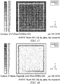
Fig. 15 is a photograph of a simulation showing molded part temperatures on the center plane during computational fluid dynamics modeling after about 30 seconds; -
Fig. 16 is a photograph of a simulation showing hot gas temperatures on the center plane during computational fluid dynamics modeling after about 30 seconds; -
Fig. 17 is a photograph of a simulation showing gas temperatures as the gas moves through the passageways formed in the test mold during computational fluid dynamics modeling after about 353 seconds; and -
Fig. 18 is a photograph of a simulation showing gas velocities as the gas moves through the passageways formed in the test mold tool during computational fluid dynamics modeling after about 353 seconds. - A
molding system 10 in accordance with the present disclosure includes afirst mold unit 11 and asecond mold unit 12 as suggested inFigs. 2-7 . Together, the first andsecond mold units mold cavity 14 there between that is formed in the molding system. During amolding process 100, an uncured product is located between themold units mold cavity 14 where heat and pressure are applied to the uncured product to provide a cured product as shown inFig. 1 . The uncured product includes uncured binder and fibers. In one example, the fibers are glass. - Each
mold unit inner surface 20 configured to engage and mate with the uncured product and provide a shape to the cured product. Eachmold unit passageway 22 through which a pressurized gas is communicated thereto as shown inFigs. 3 and7 . Anarray 24 of holes is formed in theinner surface 20 of eachmold unit passageway 22 to allow the pressurized gas to move from a gas source, through thepassageway 22, out of thearray 24 of holes, and into themold cavity 14. - In one example, the
mold unit 11 is aplaten 11P used to form relatively flat cured products as suggested inFigs. 4-7 . In another example, themold unit 11 is atool 11T used to form contoured or curved cured products as suggested inFigs. 2 and 3 . Themold unit 11 is made, for example, of metal and heated so that themold unit 11 remains hot throughout themolding process 100. - In an example of use, pressurized gas is provided by a gas source at a relatively cool temperature. The cool temperature may be about 21 degrees Celsius (about 70 degrees Fahrenheit). The pressurized gas is provided to the
passageway 22 where the gas moves through aperimeter portion 22P of the passageway which extends along aperimeter 26 of the mold unit as suggested inFigs. 3 and7 . As the pressurized gas moves along theperimeter portion 22P of thepassageway 22, heat from themold unit 11 is transferred to the pressurized gas to provide a hot pressurized gas that is then admitted to adistribution portion 22D of the passageway as shown inFigs. 3 and7 . The hot gas is then discharged from thedistribution portion 22D through thearray 24 of holes into the uncured product located in themold cavity 14. - Uncured binder included in the uncured product is cured through the application of heat so that a cured product is provided. Heat is transferred to the uncured product by conduction from the
mold unit 11 and through convection from the hot gas. In one example, an uncured product, labeled Sample 1 in Table 1 below, is cured in a mold unit by only conduction in about 7.1 minutes.
In comparison, the same uncured product is cured in the same mold unit using conduction and convection in about 2.0 minutes. In Sample 1, the binder used in the uncured product is a substantially formaldehyde-free binder. The addition of convective heat transfer via the hot gas causes at least a 70% decrease in cycle time when using a substantially formaldehyde-free binder. - Examples of formaldehyde-free binders and their chemistry are described in
U.S. Patent Nos. 7,854,980 B2 ,5,977,232 ,7,803,879 ,6,699,945 ,5,318,990 ,6,194,512 , PCT publicationPCT/US2006/028929 ,U.S. Applications 11/67541312/599858 WO2011/138459 A1 andWO201 1/022668 ,EP1 732968 , Patent ApplicationsEP2386394 andEP2199332A1 , Patent ApplicationsUS2009/0275699 , and2007/0292619 . - In comparison, another uncured product, labeled Sample 4 in Table 1 below, is cured in a mold unit by only conduction in about three minutes. In comparison, the same uncured product is cured in the same mold unit using conduction and convection in about 1.5 minutes. In Sample 4, the binder used in the uncured product is phenol-formaldehyde (PF) binder which may cure faster at lower temperatures. The addition of convective heat transfer via the hot gas causes at least a 50% decrease in cycle time when using a PF binder.
Table 1. Comparison of cycle times to full cure of an uncured product for various product types and binder types. Cycle time (min) Sample Full Cure No Convection Heating Full Cure with Convection Heating 1 Formaldehyde-Free Binder, 172/97 (top/bottom) holes/m2 (16/9 (top/bottom) holes/sq.ft.), 64.1kg/m3 (41b/cubic foot) density, 15% LOI, 2.5cm (1inch)Loft, 193 degrees Celsius (380 degrees Fahrenheit), staggered hole locations, 10.3 Nm3/h (6 scfm) per mold tool, 20.6 Nm3/h (12 scfm) total 7.10 2.00 2 Formaldehyde-Free Binder, 172/97 (top/bottom) holes/m2 (16/9 (top/bottom) holes/sq.ft.), 64.1kg/m3 (41b/cubic foot) density, 15% LOI, 2.5cm (1inch)Loft, 193 degrees Celsius (380 degrees Fahrenheit), staggered hold locations 20.6 Nm3/h (12 scfm) top mold tool, 17.2 Nm3/h (10 scfm) bottom mold tool, 37.8 Nm3/h (22 scfm) total 7.1 1.5 3 Formaldehyde-Free Binder, 1905/1905 (top/bottom) holes/m3 (177/177 (top/bottom) holes/sq.ft.), 64.1 kg/m3(41b/cubic foot) density, 15% LOI, 2.5cm (1inch)Loft, 193 degrees Celsius (380 degrees Fahrenheit), aligned hole locations, 20.6 Nm3/h (12 scfm) per mold tool, 14.0 Nm3/h (24 scfm) total 7.1 1.2 4 PF Binder, 172/97 (top/bottom) holes/m2 (16/9 (top/bottom) holes/sq.ft.), 64.1 kg/m3 (41b/cubic foot) density, 15% LOI, 2.5cm (1 inch) Loft, 193 degrees Celsius (380 degrees Fahrenheit), 10.3 Nm3/h (6 scfm) per mold tool, 20.6 Nm3/h (12 scfm) total 3.00 1.50 - A
molding process 100 in accordance with the present disclosure uses themolding system 10 of the present disclosure as shown inFig. 1 . Themolding process 100 includes several operations that provide a hot gas to an uncured blank located in themold cavity 14 of the mold system to cause curing of uncured binder included in the uncured blank to be cured via convective heat transfer from the hot gas to the uncured blank. - In the example, the uncured blank includes an outer trim layer, a first blanket, a second blanket, and an inner trim layer. Each blanket is made of a substrate and an uncured binder. In one example, the substrate is a fiber. For example, the fiber is glass, cellulose, or mineral wool. In still yet another example, the substrate may be a laminate or a veneer. For example, the laminate or veneer is a wood chip or wood particle. In addition, the uncured blank may have any number of blankets and trim layers. In addition, the uncured blank may include a thermoplastic layer, also called an interleaf, located between each neighboring pair of blankets to interconnect the neighboring pairs of blankets. The thermoplastic layer may also be located between the trim layer and the blanket.
- As shown in
Fig. 1 , themolding process 100 begins with anoperation 102 in which an uncured blank is inserted into themold cavity 14 of themolding system 10. Themolding process 100 then proceeds to anoperation 104 in which themolding system 10 is moved to the closed position trapping the uncured blank in themold cavity 14. Themolding process 100 then proceeds to anoperation 106 in which heat is transferred from theinner surface 20 of the mold system 28 to the uncured blank via conductive heat transfer to begin curing the binder included in the uncured blank as suggested inFig. 1 . - The
molding process 100 then proceeds to anoperation 108 in which heat is transferred from themolding system 10 to a cool pressurized gas to establish a hot pressurized gas as suggested inFig. 1 . The cool pressurized gas, for example, has a temperature of about 23 degrees Celsius (about 74 degrees Fahrenheit). In another example, the cool pressurized gas has a temperature similar to room temperature. The hot pressurized gas, for example, has a temperature of about 38 degrees Celsius (about 100 degrees Fahrenheit) to about 149 degrees Celsius (about 300 degrees Fahrenheit). In another example, the hot pressurized gas has a temperature of about 149 degrees Celsius (about 300 degrees Fahrenheit) to about 260 degrees Celsius (about 500 degrees Fahrenheit). - Once the hot pressurized gas is established, the
molding process 100 proceeds to anoperation 110 as shown inFig. 1 . During theoperation 110, the hot pressurized gas is injected through thearray 24 of holes formed in theinner surface 20 into the mold cavity of themolding system 10. - The
molding process 100 then proceeds to anoperation 112 in which heat from the hot pressurized gas is transferred from the hot pressurized gas to the uncured blank via convective heat transfer. As a result, uncured binder included in the uncured blank is cured at a relatively faster rate than the conductive heat transfer alone. In one example, thearray 24 of holes may be configured to move more hot pressurized gas through specific areas of the uncured blank that may require increased heat flux. - The
molding process 100 then proceeds to anoperation 114 in which the cured product is established. The cured product has had sufficient heat transferred to the uncured blank to cause substantially all of the binder to be cured. - The
molding process 100 then proceeds to anoperation 116 in which the pressurized gas is vented from themold cavity 14. Venting may occur on theother mold unit mold unit array 24 of holes. Venting may also occur on an edge of the mold system as described earlier. Venting may also be continuous or intermittent. Venting through a perimeter of the cured product minimizes the risk of fouling of thearray 24 of holes and thepassageway 22 in themold units - The
molding process 100 then proceeds to anoperation 118 in which themolding system 10 is opened to allow access to themold cavity 14. The process then proceeds to anoperation 120 in which the cured product is removed from themold cavity 14 as suggested inFig. 1 . - The
molding process 100 may be used with existing infrastructure. As a result, capital costs may be minimized when implementing themolding process 100. For example, an existing mold tool may be drilled to form the passageways and holes so that pressurized gas may be heated and transferred to the mold cavity. - The
molding process 100 also provides for even curing of the binder included in the uncured blank. Themolding process 100 achieves this result by minimizing a temperature gradient between the surface temperature of theinner surface 20 of themolding system 10 and the core temperature of the cured product. In addition, the entire uncured blank may heat up evenly with minimal temperature variations. As a result hot and cold spots in the uncured blank may be minimized. - The
molding process 100 may also provide for dimensionally stable cured products with maximized through-put and reliability. Themolding process 100 also provides for consistently fully cured products. The cured products are formed in a mold system with a minimum cycle time regardless of product variations (product density, binder distribution, binder gobs, binder wet spots, etc.) Themolding process 100 also is configured to provide cured products including a non-permeable membrane or barrier. - In a modified molding process, the
molding process 100 may be used to shape mold the uncured blank. Shape molding is a process by which the uncured blank is intentionally only partly cured. The degree of cure is generally chosen to ensure that the uncured blank retains its shape from themolding system 10 and satisfies all dimensional requirements when the shaped product is removed from themold cavity 14. Some portions of a shaped product, typically portions in the core, are not fully cured. The shape-molded part is subjected to a subsequent secondary curing process to ensure full cure. - As an example, the shape-molding process allows for relatively short cycle times and simplified design of the
array 24 of holes. It was found that themolding process 100 provides for relatively short shape-molding times. The shaped products are then subjected to a secondary curing process, for instance heating the parts in-line or in a batch. It was found that the secondary curing step is a suitable process to obtain consistently cured products independent of product variations (i.e. variations of product density, wet spots, binder globs, etc.) - In one example, the
mold units passageway 22 in the platens for passing the pressurized air into themold cavity 14. - In another example, the
mold units - The pressurized gas is passed through the
passageway 22 and heat is transferred to the pressurized gas to establish a hot pressurized gas. The pressurized gas is provided by a source which may be regulated. According to the disclosure, the pressurized gas is compressed air, for example, compressed air supplied at a relative pressure of greater than about 103 kilo Pascal (about 15 pounds per square inch), for example greater than: about 207 kilo Pascal (about 30 pounds per square inch) or 317 kilo Pascal (about 46 pounds per square inch) and/or less than about 965 kilo Pascal (about 140 pounds per square inch), for example less than about: 827 kilo Pascal (about 120 pounds per square inch) or 689 kilo Pascal (about 100 pounds per square inch). The pressurized gas may be provided by a blower. The source should provide sufficient pressure to the pressurized gas to move the pressurized gas through thepassageway 22, thearray 24 of holes, and the uncured blank. However, the pressure should be limited so as not to damage the uncured blank. - In an example of use, the pressurized air flow is switched off when the
molding system 10 is in the opened position and is not turned back on until themolding system 10 has returned to the closed position. In order to minimize cure cycle time and deformation of the cured product, the air flow may be increased gradually from low velocity to high velocity from start to end of the cure cycle. - The
molding process 100 andmolding system 10 provide several surprising results. One surprising result is that despite thearray 24 of holes and thepassageway 22 not necessarily having even heat flow, the cured products show a relatively even cure and do not have localized cold spots. Another surprising result is that themolding process 100 provides cured products even when the uncured blank has portions that are relatively very dense that normally restrict air flow. Still yet another surprising result is thatmolding process 100 may be used with cured products including a membrane located in the middle of the cured product that may operate to restrict air flow. Another surprising result is that themolding process 100 andmolding system 10 may be used to fully cure cured products in relatively very short cycle times as shown in Table 2 below. Finally, another surprising result is that themolding process 100 provides the cured product even when the cured product includes relatively heat sensitive materials.Table 2. Comparison of cycle times to full cure of an uncured product for various product types and binder types with and without shape molding. Cycle time (min) Sample Shape Molding No Convection Heating Shape Molding with Convection Heating Full Cure No Convection Heating Full Cure with Convection Heating 1 Formaldehyde-Free Binder, 172/97 (top/bottom) holes/m2 (16/9 (top/bottom) holes/sq.ft.), 64.1kg/m3 (41b/cubic foot) density, 15% LOI, 2.5cm (1inch) Loft, 193 degrees Celsius (380 degrees Fahrenheit), staggered hole locations, 10.3 Nm3/h (6 scfm) per mold tool, 20.6 Nm3/h (12 scfm) total 5.5 1.0 7.1 2.0 2 Formaldehyde-Free Binder, 172/97 (top/bottom) holes/m2 (16/9 (top/bottom) holes/sq.ft.), 64.1kg/m3 (41b/cubic foot) density, 15% LOI, 2.5cm (1inch) Loft, 193 degrees Celsius (380 degrees Fahrenheit), staggered hold locations 20.6 Nm3/h (12 scfm) top mold tool, 17.2 Nm3/h (10 scfm) bottom mold tool, 37.8 Nm3/h (22 scfm) total 5.5 1.0 7.1 1.5 3 Formaldehyde-Free Binder, 1905/1905 (top/bottom) holes/m3 (177/177 (top/bottom) holes/sq.ft.), 64.1 kg/m3 (41b/cubic foot) density, 15% LOI, 1inch Loft, 193 degrees Celsius (380 degrees Fahrenheit), aligned hole locations, 20.6 Nm3/h (12 scfm) per mold tool, 14.0 Nm3/h (24 scfm) total 5.5 7.1 1.2 4 PF Binder, 172/97 (top/bottom) holes/m2 (16/9 (top/bottom) holes/sq.ft.), 64.1 kg/m3 (41b/cubic foot) density, 15% LOI, 1 inch Loft, 193 degrees Celsius (380 degrees Fahrenheit), 10.3 Nm3/h (6 scfm) per mold tool, 20.6 Nm3/h (12 scfm) total 3.0 1.0 > 3.0 1.5 - The
molding process 100 may include flow control elements to control the flow of the pressurized gas. As a result, heat transfer may be optimized. - Various binder chemistries may be used as part of the molding processes described herein. Furthermore, temperature sensitivity of the cured products may also be taken into account. While temperatures of the platens or mold tools may be increased to provide shorter cycle times, temperatures are limited to those temperatures where decomposition of the binder, the trim layer, the facing materials, and the cured product does not occur due to excessive heat.
- In addition, existing platens and mold tools may be retrofitted to perform according the
molding process 100 and establish themolding system 10 of the present disclosure. As a result, capital costs for implementing the molding process are minimized while obtaining minimized cycle time and the use of various binders. - Flow distribution of hot gas through the molded part may be optimized. Optimization may include optimizing the pattern of holes, hole size, and hole locations.
- Cross flow through the uncured blank is possible. Cross flow may be used when a perimeter of the cured product is extremely dense. Extreme density at the perimeter edge may occur due to a pinched edge, for example.
- Cycle time is reduced as a result of blowing, for example, air through heated platens or mold tools rather than blowing hot air through an unheated platen or tool. In addition, blowing hot air through an unheated platen or mold tool is needed to keep the platen or mold tool hot while the platen or mold tool is open. If this is not done, the platen or mold tool may cool and a longer cycle time may be needed. As a result of passing hot air through an unheated mold unit, energy efficiency is reduced.
- The
mold units passageway 22. Thepassageway 22 may take on various shapes or patterns as may be needed for specific platen ormold unit passageway 22 includes a minimum passageway length that is a factor of desired gas flow rate, tool temperature, and required hot-gas temperature. In one illustrative example shown inFigs. 3 and7 , thepassageway 22 is formed along a perimeter of the mold tool (Fig. 3 ) and a perimeter of the platen (Fig. 7 ). After the cool gas is moved through the perimeter portion of thepassageway 22, sufficient heat may have been transferred from themold units distribution portion 22D of thepassageway 22. - In one example, the
passageway 22 is formed in a mold tool which is coupled to a platen to move therewith. The platen is formed to include an electrical or oil-based heating system which provides heat to the mold tool. However, the tool may be formed to include an electrical or oil-based heating system in addition to the air passageway as suggested inFigs. 2-7 . - A platen may be formed with a routing path for heating elements as shown in
Fig. 5 . The heating elements may be electrical pencil heaters. Each electrical pencil heater may be spaced apart from each neighboring electrical pencil a distance of about 5.1 centimeters (about two inches) to about 15.2 centimeters (about six inches). In another example, a platen may be heated with hot oil that flows through a serpentine or snake-like channel system (plug flow, re-circulating heated oil). In another example, heating elements may be included in a tool where heat is transferred to the tool from a platen to compensate for locations in the tool where heating is uneven. Heating may be uneven as a result of having a large distance between the heated platen and the inner surface of the mold tool. - In some examples, heated platens may be used in place of mold tools when molding flat panel parts. Flat panel parts include, for example, panels used in office cubical walls. When platens are used to mold parts, heating elements and gas passageways may both be located in the platens. The location of both relative to each other can vary in a wide range, but proper heat transfer to the cold pressurized gas should be considered.
- In instances where parts have curve(s) or are non-flat, mold tools may be used. Non-flat parts include, for example, hood liners for automobiles.
- The
array 24 of holes formed in theinner surface 20 of themold units Figs. 2 and4 . The distance between each hole and a neighboring hole in the array of holes may vary. In one example, the distance is about 1.3 centimeters (about 0.5 inches) to about 15.2 centimeters (about six inches). In another example, the distance is about 2.5 centimeters (about one inch) to about 7.6 centimeters (about three inches). - In one example, the array of
holes 24 for providing the hot pressurized gas may be formed only on one mold tool. A separate array of holes may be formed on the opposite mold tool to vent the pressurized gas after it passes through the uncured blank. - In another example, the
array 24 of holes for providing the hot pressurized gas may be present on both mold tools. As a result, the pressurized gas may be vented along a perimeter of the uncured blank. Perimeter venting may be used where an uncured blank has a high density along a perimeter causing a high pressure drop of the hot gas. The perimeter edge may be perforated to minimize flow resistance and pressure drop. - The diameter of each hole in the array of holes may be dependent upon product appearance as dimpling by high velocity gas or embossing textures in high density areas of the molded part should be minimized. In one example, holes may have a diameter of about 0.04 of a centimeters (about 1/64 of an inch) to about 0.16 centimeters (about 1/16 inch). In another example, vented set screws may be formed with a hole having a diameter of about 0.11 centimeters(about 0.042 inches) to about 0.40 centimeters (about 0.156 inches). The diameter of holes included in the array of holes may be constant throughout or the diameter may vary from hole to hole.
- A cured product in accordance with the present disclosure may be used for sound absorption or as a thermal shield. Sound absorption may be desired in flat architectural applications (i.e. wall system for office spaces and theatres) and contoured parts in automotive applications (i.e. hood liners). Some molded parts are used in Original Equipment Manufacturers (OEM) equipment for sound absorption (HVAC equipment, clothes washers, clothes dryers, dishwashers, etc.)
- A cured product may have a width of about 2.5 centimeters (about one inch) to about 1.8 meters (about six feet). A cured product may have a length of about 5.0 centimeters (about two inches) to about 3.6 meters (about twelve feet). The cured product may have a thickness of about 0.3 centimeters (about 1/8 of an inch) to about 5.0 centimeters (about two inches) in one example. In another example, the cured product may have a thickness less than 0.3 centimeters (1/8 of an inch) and greater than 5.0 centimeters (two inches). The cured product may have a density of about 16.0 kilograms per cubic meter (about 1 pound per cubic foot) to about 800.9 kilograms per cubic meter (about 50 pounds per cubic foot). In addition, the density of the cured product may vary throughout the cured product.
- The cured product may be subjected to a molding temperature when the binder included in the molded part is being cured. The molding temperature may vary according to the fibers and binder used in the molded part. Each binder may have a different minimum molding temperature at which the binder cures. A maximum molding temperature is established at the point in which decomposition, melting, and thermal instability of the fibers, binder, and trim layers occurs. In one illustrative example, the molding temperature is about 93 degrees Celsius (about 200 degrees Fahrenheit) to about 260 degrees Celsius (about 500 degrees Fahrenheit). As a result, the hot gas has a hot-gas temperature of about 93 degrees Celsius (about 200 degrees Fahrenheit) to about 260 degrees Celsius (about 500 degrees Fahrenheit).
- A sample mold tool including six thermocouples TC1, TC2, TC3, TC4, TC5, TC6 was used for testing and modeling heat transfer and temperatures of a sample molded part and is shown in
Fig. 9 . During a test, an outer surface of each mold tool was heated to about 204 degrees Celsius (about 400 degrees Fahrenheit). Cool air flowing at a rate of about 16.8 scfm and about 23 degrees Celsius (about 74 degrees Fahrenheit) was admitted to the mold tools to flow through the mold tool and absorb heat from the tool. The change in temperature for each thermocouple TC1, TC2, TC3, TC4, TC5, TC6 is shown over a time span of about 210 seconds in a graph shown inFig. 8 . Also, a computational fluid dynamics model of the test mold tool and molded part was prepared and the results are shown as solid lines on the graph ofFig. 8 . Each thermocouple TC1, TC2, TC3, TC4, TC5, TC6 is shown as a different symbol having a different color. The modeled temperatures are shown with colors matching the associated thermocouple locations. In general, both the overall trend of the model and the test match; indicating predictable, reproducible results as suggested inFig. 8 .
Claims (11)
- A method of making a molded mineral wool insulation product using a molding process comprising
inserting an uncured blank in a mold cavity (14) formed in a mold system (28), the uncured blank including fiber and uncured binder, characterized in that the method comprises
transferring heat from a first (11) and/or second (12) mold unit of the mold system to a cool pressurized gas to establish a hot pressurized gas, the first and/or second mold unit being heated with hot oil, with electrical resistance, heated platens, or any combination thereof and the first and/or second mold unit being formed to include a passageway (22) in fluid connection with a source of the cool pressurized gas and an array of holes formed in the first mold unit that are arranged to open into the passageway (22) to cause pressurized gas to be communicated from the passageway to the mold cavity and causing the pressurized gas to flow through the passageway so that heat is transferred from the heated mold unit to the pressurized gas to cause a hot pressurized gas to be established prior to the hot pressurized gas entering the mold cavity,
wherein the pressurized gas is compressed air,
injecting the hot pressurized gas into the mold cavity (14), and
transferring heat by convection from the hot pressurized gas to the uncured blank and transferring heat by conduction from the mold system to the uncured blank to cause the uncured binder to cure and establish a cured product. - A method in accordance with claim 1, wherein the uncured binder is substantially free of formaldehyde.
- A method in accordance with any preceding claim, wherein the pressurized gas has a cold-gas temperature of no more than 27 °C (about 80 degrees Fahrenheit) and the hot pressurized gas has a hot-gas temperature selected from :a hot-gas temperature of about 38 degrees Celsius (about 100 degrees Fahrenheit) to about 149 degrees Celsius (about 300 degrees Fahrenheit); anda hot-gas temperature of about 93 degrees Celsius (about 200 degrees Fahrenheit) to about 260 degrees Celsius (about 500 degrees Fahrenheit.
- A method in accordance with any preceding claim, wherein the pressurized gas has a pressure and flow rate configured to minimize dimpling and deformation of an uncured blank in the mold cavity.
- A method in accordance with any preceding claim, wherein the passageway (22) includes a perimeter portion (22P) and a distribution portion (22D), the perimeter portion being be arranged to extend around a perimeter of its mold unit to cause heat to be transferred from the mold unit to the pressurized gas to establish the hot pressurized gas and the distribution portion being in fluid communication with the perimeter portion and in fluid communication with the array of holes to cause the hot pressurized gas to be delivered to the mold cavity.
- A method in accordance with any preceding claim, wherein the mold system comprises
the first mold unit (11) and
the second mold unit (12), the second mold unit being coupled to the first mold unit to move relative to the first mold unit between a closed position in which the mold cavity is defined between the first and the second mold units and an opened position in which the second mold unit is spaced apart from the first mold unit, the second mold unit being coupled to a heat source to cause the second mold unit to be at a molding temperature,
wherein the second mold unit is formed to include a passageway in fluid connection with a source of pressurized gas and an array of holes formed in the second mold unit that are arranged to open into the passageway to cause pressurized gas to be communicated from the passageway to the mold cavity when the second mold unit is in the closed position, and wherein the pressurized gas flows through the passageway absorbing heat from the second mold unit to cause the hot pressurized gas to be established prior to the hot pressurized gas entering the mold cavity. - A method in accordance with claim 6, wherein the first mold unit (11) is coupled to a heat source to cause the first mold unit to be at the molding temperature and wherein the first mold unit is formed to include a passageway in fluid connection with the source of pressurized gas and an array of holes is formed in the first mold unit that are arranged to open into the passageway to cause pressurized gas to be communicated from the passageway to the mold cavity when the second mold unit is in the closed position to cause heat to be transferred from the first mold unit to the pressurized gas to cause the hot pressurized gas to be established prior to the hot pressurized gas entering the mold cavity.
- A method in accordance with any preceding claim, wherein the hot pressurized gas is vented through a perimeter (26) of the mold system after the hot pressurized gas has moved through the mold cavity.
- A method in accordance with claim 7, wherein each hole in the array of holes (24) of the first mold unit is aligned with an associated hole in the array of holes in the second mold unit to cause the array of holes in the first mold unit to be a mirror of the array of holes in the second mold unit.
- A method in accordance with claim 7, wherein the array (24) of holes of the first mold unit is offset from the array of holes of the second mold unit to cause convective heat transfer from the hot pressurized gas to be maximized.
- A method in accordance with claim 7, wherein the first mold unit is formed to include a vent passageway in fluid connection with atmosphere surrounding the mold system and an array of vent holes formed in the first mold unit that are arranged to open into the vent passageway to cause the hot pressurized gas to be communicated from mold cavity to the vent passageway after the hot pressurized gas moves through the mold cavity.
Applications Claiming Priority (3)
| Application Number | Priority Date | Filing Date | Title |
|---|---|---|---|
| US201261625888P | 2012-04-18 | 2012-04-18 | |
| US201361779713P | 2013-03-13 | 2013-03-13 | |
| PCT/US2013/037129 WO2013158853A1 (en) | 2012-04-18 | 2013-04-18 | Molding apparatus and process |
Publications (2)
| Publication Number | Publication Date |
|---|---|
| EP2838703A1 EP2838703A1 (en) | 2015-02-25 |
| EP2838703B1 true EP2838703B1 (en) | 2019-06-12 |
Family
ID=48237285
Family Applications (1)
| Application Number | Title | Priority Date | Filing Date |
|---|---|---|---|
| EP13720195.0A Active EP2838703B1 (en) | 2012-04-18 | 2013-04-18 | Molding process |
Country Status (6)
| Country | Link |
|---|---|
| US (3) | US20150091209A1 (en) |
| EP (1) | EP2838703B1 (en) |
| BR (1) | BR112014025867B1 (en) |
| CA (1) | CA2870898C (en) |
| MX (1) | MX374407B (en) |
| WO (1) | WO2013158853A1 (en) |
Families Citing this family (14)
| Publication number | Priority date | Publication date | Assignee | Title |
|---|---|---|---|---|
| EP3017930A1 (en) * | 2014-11-07 | 2016-05-11 | Compagnie Plastic Omnium | Mould for overmolding with means for heating a composite insert |
| CN105082447B (en) * | 2015-09-11 | 2017-09-05 | 临海市泽福泡沫制品有限公司 | A kind of vapor-water type foam mold |
| DE102016113201B4 (en) * | 2016-07-18 | 2019-07-18 | Johann Borgers GmbH | Process for the production of a porous fibrous nonwoven shaped article by means of a thermal shaping method and device suitable therefor |
| US11534992B2 (en) * | 2019-03-04 | 2022-12-27 | The Boeing Company | Tooling assembly and associated system and method for manufacturing a porous composite structure |
| US12269384B2 (en) | 2021-03-31 | 2025-04-08 | Lear Corporation | Seat support |
| US12319183B2 (en) | 2021-03-31 | 2025-06-03 | Lear Corporation | Seat support |
| US11807143B2 (en) | 2021-12-02 | 2023-11-07 | Lear Corporation | Vehicle seating system and method for producing same |
| US12479143B2 (en) | 2021-12-20 | 2025-11-25 | Lear Corporation | System and method of making a mesh cushion |
| US12325168B2 (en) | 2021-12-20 | 2025-06-10 | Lear Corporation | System and method of making a mesh cushion |
| US12384094B2 (en) | 2022-03-08 | 2025-08-12 | Lear Corporation | Method for producing a vehicle interior component |
| US12454111B2 (en) | 2022-05-11 | 2025-10-28 | Lear Corporation | Tool to manufacture a cushion |
| US12509343B2 (en) | 2023-02-28 | 2025-12-30 | Lear Corporation | Automated trench manufacturing and assembly for attaching trim covers to a cushion assembly |
| US12325624B2 (en) * | 2023-03-06 | 2025-06-10 | Lear Corporation | Seat assembly, cushion, and tool and method of forming |
| US12286044B2 (en) | 2023-05-12 | 2025-04-29 | Lear Corporation | Method and apparatus for producing a vehicle interior component |
Family Cites Families (34)
| Publication number | Priority date | Publication date | Assignee | Title |
|---|---|---|---|---|
| US3280237A (en) * | 1963-04-22 | 1966-10-18 | Weyerhaeuser Co | Method of pressing composite consolidated articles |
| US3891738A (en) * | 1972-11-10 | 1975-06-24 | Canadian Patents Dev | Method and apparatus for pressing particleboard |
| US4115498A (en) * | 1976-02-27 | 1978-09-19 | Owens-Corning Fiberglas Corporation | Method and apparatus for molding articles from fibrous material |
| US4379101A (en) * | 1980-06-04 | 1983-04-05 | Allen Industries, Inc. | Forming apparatus and method |
| US4393019A (en) * | 1981-11-30 | 1983-07-12 | The United States Of America As Represented By The Secretary Of Agriculture | Method of pressing reconstituted lignocellulosic materials |
| FR2542666B1 (en) * | 1983-03-17 | 1986-06-20 | Saint Gobain Isover | COMPOSITE MOLDED PANELS |
| US4517147A (en) * | 1984-02-03 | 1985-05-14 | Weyerhaeuser Company | Pressing process for composite wood panels |
| US4786351A (en) * | 1985-12-31 | 1988-11-22 | Astechnologies, Inc. | Process and apparatus for simultaneously shaping foam and laminating fabric thereto |
| US5087311A (en) * | 1986-09-09 | 1992-02-11 | Astechnologies, Inc. | Process of laminating fabric to a concave substrate |
| US4850849A (en) * | 1988-04-29 | 1989-07-25 | Forintek Canada Corp. | Apparatus for steam pressing compressible mat material |
| US5824246A (en) * | 1991-03-29 | 1998-10-20 | Engineered Composites | Method of forming a thermoactive binder composite |
| DE4142261A1 (en) * | 1991-12-20 | 1993-06-24 | Man Technologie Gmbh | Coating and infiltration of substrates in a short time - by heating substrate using body which matches the component contour at gas outflow side and opt. gas entry side |
| US5820801A (en) * | 1992-05-12 | 1998-10-13 | The Budd Company | Reinforced thermoplastic molding technique method |
| DE4233622C2 (en) * | 1992-10-06 | 2000-01-05 | Rolf Hesch | Pressing process for coating a workpiece and press for carrying out the process |
| CA2101765C (en) * | 1993-05-17 | 1999-03-16 | Earl K. Phillips | Method for bonding lignocellulosic material with phenol-formaldehyde resin and carbon dioxide |
| US5318990A (en) | 1993-06-21 | 1994-06-07 | Owens-Corning Fiberglas Technology Inc. | Fibrous glass binders |
| AUPO380596A0 (en) * | 1996-11-25 | 1996-12-19 | Commonwealth Scientific And Industrial Research Organisation | Manufacture of reconstituted wood products |
| US5977232A (en) | 1997-08-01 | 1999-11-02 | Rohm And Haas Company | Formaldehyde-free, accelerated cure, aqueous composition for bonding glass fiber heat-resistant nonwovens |
| US6471897B1 (en) * | 1998-11-04 | 2002-10-29 | Masonite Corporation | Composite article and method of making same |
| US6194512B1 (en) | 1999-06-28 | 2001-02-27 | Owens Corning Fiberglas Technology, Inc. | Phenol/formaldehyde and polyacrylic acid co-binder and low emissions process for making the same |
| US6699945B1 (en) | 2002-12-03 | 2004-03-02 | Owens Corning Fiberglas Technology, Inc. | Polycarboxylic acid based co-binder |
| DE10337117A1 (en) * | 2003-08-11 | 2005-03-17 | Dieffenbacher Gmbh + Co. Kg | Process and single or multi-daylight press for the production of wood-based panels, especially OSB panels |
| US7842382B2 (en) | 2004-03-11 | 2010-11-30 | Knauf Insulation Gmbh | Binder compositions and associated methods |
| CA2615780C (en) | 2005-07-26 | 2020-03-10 | Knauf Insulation Gmbh | Binders and materials made therewith |
| US7872088B2 (en) | 2006-02-16 | 2011-01-18 | Knauf Insulation Gmbh | Low formaldehyde emission fiberglass |
| US7795354B2 (en) | 2006-06-16 | 2010-09-14 | Georgia-Pacific Chemicals Llc | Formaldehyde free binder |
| US7803879B2 (en) | 2006-06-16 | 2010-09-28 | Georgia-Pacific Chemicals Llc | Formaldehyde free binder |
| CN101688343B (en) | 2007-01-25 | 2011-12-14 | 可耐福保温材料有限公司 | Formaldehyde-free mineral fiber insulation products |
| GB0715100D0 (en) | 2007-08-03 | 2007-09-12 | Knauf Insulation Ltd | Binders |
| JP4927066B2 (en) | 2007-12-26 | 2012-05-09 | ローム アンド ハース カンパニー | Curable composition |
| US20090275699A1 (en) | 2008-05-05 | 2009-11-05 | Mingfu Zhang | Starch containing formaldehyde-free thermoset binders for fiber products |
| US8193107B2 (en) | 2009-08-20 | 2012-06-05 | Georgia-Pacific Chemicals Llc | Modified binders for making fiberglass products |
| EP2386394B1 (en) | 2010-04-22 | 2020-06-10 | Rohm and Haas Company | Durable thermoset binder compositions from 5-carbon reducing sugars and use as wood binders |
| MY160846A (en) | 2010-05-07 | 2017-03-31 | Knauf Insulation | Carbohydrate binders and materials made therewith |
-
2013
- 2013-04-18 BR BR112014025867-8A patent/BR112014025867B1/en active IP Right Grant
- 2013-04-18 MX MX2014012666A patent/MX374407B/en active IP Right Grant
- 2013-04-18 US US14/394,665 patent/US20150091209A1/en not_active Abandoned
- 2013-04-18 EP EP13720195.0A patent/EP2838703B1/en active Active
- 2013-04-18 CA CA2870898A patent/CA2870898C/en active Active
- 2013-04-18 WO PCT/US2013/037129 patent/WO2013158853A1/en not_active Ceased
-
2017
- 2017-12-13 US US15/841,187 patent/US10889026B2/en active Active
-
2020
- 2020-08-21 US US17/000,247 patent/US11318639B2/en active Active
Non-Patent Citations (1)
| Title |
|---|
| None * |
Also Published As
| Publication number | Publication date |
|---|---|
| WO2013158853A1 (en) | 2013-10-24 |
| MX374407B (en) | 2025-03-06 |
| US10889026B2 (en) | 2021-01-12 |
| MX2014012666A (en) | 2015-04-08 |
| CA2870898C (en) | 2019-03-12 |
| US20200384668A1 (en) | 2020-12-10 |
| EP2838703A1 (en) | 2015-02-25 |
| CA2870898A1 (en) | 2013-10-24 |
| BR112014025867B1 (en) | 2021-02-23 |
| US11318639B2 (en) | 2022-05-03 |
| US20150091209A1 (en) | 2015-04-02 |
| US20180104860A1 (en) | 2018-04-19 |
Similar Documents
| Publication | Publication Date | Title |
|---|---|---|
| US11318639B2 (en) | Molding apparatus and process | |
| US7159836B2 (en) | Flow through molding apparatus and method | |
| US20090074905A1 (en) | Method and apparatus for resin transfer molding composite parts | |
| JP2016511738A5 (en) | ||
| AR032302A1 (en) | METHOD FOR PRODUCING A BASKET OF HYBRID LEAVES | |
| KR20130068487A (en) | Press system for warm sheet forming | |
| CN106457338B (en) | Hot forming die quenching | |
| EP1824660B1 (en) | Method for deforming a thermosetting plate | |
| HU220998B1 (en) | Method and installation for manufacturing decorative panels | |
| JP2010216056A (en) | Uniform heating method of air permeable board | |
| US20200269488A1 (en) | Molding process for insulation product | |
| CN215039402U (en) | Glass body mould for thermoplastic material forming | |
| JP2017530040A (en) | Thermoforming method and equipment for thermoplastic material | |
| WO2009079052A3 (en) | Devices and methods for thermally isolating chambers of an assay card | |
| CN210911125U (en) | Engine is subregion heating mould for heat insulating mattress | |
| US20050285304A1 (en) | System and method for manufacturing plastic parts with textile covering | |
| CN202985880U (en) | Thermal pretreatment device before vulcanization used for building vibration isolation rubber bearing | |
| CN106079390A (en) | A kind of isodensity not equal thickness automobile internal partition sound heat insulating mattress process | |
| CN109079933B (en) | Improved production process of mould pressing wood piece coating melamine impregnated wear-resistant paper | |
| KR101870037B1 (en) | Apparatus and method for manufacturing curved acryl | |
| CN110181898B (en) | Bamboo fiber composite board and its manufacturing method | |
| KR102591700B1 (en) | Injection mold | |
| CN204869430U (en) | Use mould benevolence structure on hot briquetting mould | |
| CN103587131B (en) | A kind of material equalization treatment device | |
| CN117261296A (en) | A kind of hot autoclave with longitudinal counter-flow and transverse heat pipe temperature regulation |
Legal Events
| Date | Code | Title | Description |
|---|---|---|---|
| PUAI | Public reference made under article 153(3) epc to a published international application that has entered the european phase |
Free format text: ORIGINAL CODE: 0009012 |
|
| 17P | Request for examination filed |
Effective date: 20141118 |
|
| AK | Designated contracting states |
Kind code of ref document: A1 Designated state(s): AL AT BE BG CH CY CZ DE DK EE ES FI FR GB GR HR HU IE IS IT LI LT LU LV MC MK MT NL NO PL PT RO RS SE SI SK SM TR |
|
| AX | Request for extension of the european patent |
Extension state: BA ME |
|
| DAX | Request for extension of the european patent (deleted) | ||
| 17Q | First examination report despatched |
Effective date: 20160816 |
|
| STAA | Information on the status of an ep patent application or granted ep patent |
Free format text: STATUS: EXAMINATION IS IN PROGRESS |
|
| GRAP | Despatch of communication of intention to grant a patent |
Free format text: ORIGINAL CODE: EPIDOSNIGR1 |
|
| STAA | Information on the status of an ep patent application or granted ep patent |
Free format text: STATUS: GRANT OF PATENT IS INTENDED |
|
| INTG | Intention to grant announced |
Effective date: 20180907 |
|
| GRAJ | Information related to disapproval of communication of intention to grant by the applicant or resumption of examination proceedings by the epo deleted |
Free format text: ORIGINAL CODE: EPIDOSDIGR1 |
|
| STAA | Information on the status of an ep patent application or granted ep patent |
Free format text: STATUS: EXAMINATION IS IN PROGRESS |
|
| GRAP | Despatch of communication of intention to grant a patent |
Free format text: ORIGINAL CODE: EPIDOSNIGR1 |
|
| STAA | Information on the status of an ep patent application or granted ep patent |
Free format text: STATUS: GRANT OF PATENT IS INTENDED |
|
| INTC | Intention to grant announced (deleted) | ||
| INTG | Intention to grant announced |
Effective date: 20190116 |
|
| GRAS | Grant fee paid |
Free format text: ORIGINAL CODE: EPIDOSNIGR3 |
|
| GRAA | (expected) grant |
Free format text: ORIGINAL CODE: 0009210 |
|
| STAA | Information on the status of an ep patent application or granted ep patent |
Free format text: STATUS: THE PATENT HAS BEEN GRANTED |
|
| AK | Designated contracting states |
Kind code of ref document: B1 Designated state(s): AL AT BE BG CH CY CZ DE DK EE ES FI FR GB GR HR HU IE IS IT LI LT LU LV MC MK MT NL NO PL PT RO RS SE SI SK SM TR |
|
| REG | Reference to a national code |
Ref country code: GB Ref legal event code: FG4D |
|
| REG | Reference to a national code |
Ref country code: CH Ref legal event code: EP |
|
| REG | Reference to a national code |
Ref country code: AT Ref legal event code: REF Ref document number: 1142002 Country of ref document: AT Kind code of ref document: T Effective date: 20190615 |
|
| REG | Reference to a national code |
Ref country code: DE Ref legal event code: R096 Ref document number: 602013056496 Country of ref document: DE |
|
| REG | Reference to a national code |
Ref country code: IE Ref legal event code: FG4D |
|
| REG | Reference to a national code |
Ref country code: NL Ref legal event code: MP Effective date: 20190612 |
|
| REG | Reference to a national code |
Ref country code: LT Ref legal event code: MG4D |
|
| PG25 | Lapsed in a contracting state [announced via postgrant information from national office to epo] |
Ref country code: LT Free format text: LAPSE BECAUSE OF FAILURE TO SUBMIT A TRANSLATION OF THE DESCRIPTION OR TO PAY THE FEE WITHIN THE PRESCRIBED TIME-LIMIT Effective date: 20190612 Ref country code: HR Free format text: LAPSE BECAUSE OF FAILURE TO SUBMIT A TRANSLATION OF THE DESCRIPTION OR TO PAY THE FEE WITHIN THE PRESCRIBED TIME-LIMIT Effective date: 20190612 Ref country code: NO Free format text: LAPSE BECAUSE OF FAILURE TO SUBMIT A TRANSLATION OF THE DESCRIPTION OR TO PAY THE FEE WITHIN THE PRESCRIBED TIME-LIMIT Effective date: 20190912 Ref country code: FI Free format text: LAPSE BECAUSE OF FAILURE TO SUBMIT A TRANSLATION OF THE DESCRIPTION OR TO PAY THE FEE WITHIN THE PRESCRIBED TIME-LIMIT Effective date: 20190612 Ref country code: SE Free format text: LAPSE BECAUSE OF FAILURE TO SUBMIT A TRANSLATION OF THE DESCRIPTION OR TO PAY THE FEE WITHIN THE PRESCRIBED TIME-LIMIT Effective date: 20190612 Ref country code: AL Free format text: LAPSE BECAUSE OF FAILURE TO SUBMIT A TRANSLATION OF THE DESCRIPTION OR TO PAY THE FEE WITHIN THE PRESCRIBED TIME-LIMIT Effective date: 20190612 |
|
| PG25 | Lapsed in a contracting state [announced via postgrant information from national office to epo] |
Ref country code: GR Free format text: LAPSE BECAUSE OF FAILURE TO SUBMIT A TRANSLATION OF THE DESCRIPTION OR TO PAY THE FEE WITHIN THE PRESCRIBED TIME-LIMIT Effective date: 20190913 Ref country code: BG Free format text: LAPSE BECAUSE OF FAILURE TO SUBMIT A TRANSLATION OF THE DESCRIPTION OR TO PAY THE FEE WITHIN THE PRESCRIBED TIME-LIMIT Effective date: 20190912 Ref country code: RS Free format text: LAPSE BECAUSE OF FAILURE TO SUBMIT A TRANSLATION OF THE DESCRIPTION OR TO PAY THE FEE WITHIN THE PRESCRIBED TIME-LIMIT Effective date: 20190612 Ref country code: LV Free format text: LAPSE BECAUSE OF FAILURE TO SUBMIT A TRANSLATION OF THE DESCRIPTION OR TO PAY THE FEE WITHIN THE PRESCRIBED TIME-LIMIT Effective date: 20190612 |
|
| REG | Reference to a national code |
Ref country code: AT Ref legal event code: MK05 Ref document number: 1142002 Country of ref document: AT Kind code of ref document: T Effective date: 20190612 |
|
| PG25 | Lapsed in a contracting state [announced via postgrant information from national office to epo] |
Ref country code: AT Free format text: LAPSE BECAUSE OF FAILURE TO SUBMIT A TRANSLATION OF THE DESCRIPTION OR TO PAY THE FEE WITHIN THE PRESCRIBED TIME-LIMIT Effective date: 20190612 Ref country code: EE Free format text: LAPSE BECAUSE OF FAILURE TO SUBMIT A TRANSLATION OF THE DESCRIPTION OR TO PAY THE FEE WITHIN THE PRESCRIBED TIME-LIMIT Effective date: 20190612 Ref country code: NL Free format text: LAPSE BECAUSE OF FAILURE TO SUBMIT A TRANSLATION OF THE DESCRIPTION OR TO PAY THE FEE WITHIN THE PRESCRIBED TIME-LIMIT Effective date: 20190612 Ref country code: CZ Free format text: LAPSE BECAUSE OF FAILURE TO SUBMIT A TRANSLATION OF THE DESCRIPTION OR TO PAY THE FEE WITHIN THE PRESCRIBED TIME-LIMIT Effective date: 20190612 Ref country code: RO Free format text: LAPSE BECAUSE OF FAILURE TO SUBMIT A TRANSLATION OF THE DESCRIPTION OR TO PAY THE FEE WITHIN THE PRESCRIBED TIME-LIMIT Effective date: 20190612 Ref country code: SK Free format text: LAPSE BECAUSE OF FAILURE TO SUBMIT A TRANSLATION OF THE DESCRIPTION OR TO PAY THE FEE WITHIN THE PRESCRIBED TIME-LIMIT Effective date: 20190612 Ref country code: PT Free format text: LAPSE BECAUSE OF FAILURE TO SUBMIT A TRANSLATION OF THE DESCRIPTION OR TO PAY THE FEE WITHIN THE PRESCRIBED TIME-LIMIT Effective date: 20191014 |
|
| PG25 | Lapsed in a contracting state [announced via postgrant information from national office to epo] |
Ref country code: IS Free format text: LAPSE BECAUSE OF FAILURE TO SUBMIT A TRANSLATION OF THE DESCRIPTION OR TO PAY THE FEE WITHIN THE PRESCRIBED TIME-LIMIT Effective date: 20191012 Ref country code: SM Free format text: LAPSE BECAUSE OF FAILURE TO SUBMIT A TRANSLATION OF THE DESCRIPTION OR TO PAY THE FEE WITHIN THE PRESCRIBED TIME-LIMIT Effective date: 20190612 Ref country code: IT Free format text: LAPSE BECAUSE OF FAILURE TO SUBMIT A TRANSLATION OF THE DESCRIPTION OR TO PAY THE FEE WITHIN THE PRESCRIBED TIME-LIMIT Effective date: 20190612 Ref country code: ES Free format text: LAPSE BECAUSE OF FAILURE TO SUBMIT A TRANSLATION OF THE DESCRIPTION OR TO PAY THE FEE WITHIN THE PRESCRIBED TIME-LIMIT Effective date: 20190612 |
|
| REG | Reference to a national code |
Ref country code: DE Ref legal event code: R097 Ref document number: 602013056496 Country of ref document: DE |
|
| PG25 | Lapsed in a contracting state [announced via postgrant information from national office to epo] |
Ref country code: TR Free format text: LAPSE BECAUSE OF FAILURE TO SUBMIT A TRANSLATION OF THE DESCRIPTION OR TO PAY THE FEE WITHIN THE PRESCRIBED TIME-LIMIT Effective date: 20190612 |
|
| PLBE | No opposition filed within time limit |
Free format text: ORIGINAL CODE: 0009261 |
|
| STAA | Information on the status of an ep patent application or granted ep patent |
Free format text: STATUS: NO OPPOSITION FILED WITHIN TIME LIMIT |
|
| PG25 | Lapsed in a contracting state [announced via postgrant information from national office to epo] |
Ref country code: DK Free format text: LAPSE BECAUSE OF FAILURE TO SUBMIT A TRANSLATION OF THE DESCRIPTION OR TO PAY THE FEE WITHIN THE PRESCRIBED TIME-LIMIT Effective date: 20190612 Ref country code: PL Free format text: LAPSE BECAUSE OF FAILURE TO SUBMIT A TRANSLATION OF THE DESCRIPTION OR TO PAY THE FEE WITHIN THE PRESCRIBED TIME-LIMIT Effective date: 20190612 |
|
| 26N | No opposition filed |
Effective date: 20200313 |
|
| PG25 | Lapsed in a contracting state [announced via postgrant information from national office to epo] |
Ref country code: IS Free format text: LAPSE BECAUSE OF FAILURE TO SUBMIT A TRANSLATION OF THE DESCRIPTION OR TO PAY THE FEE WITHIN THE PRESCRIBED TIME-LIMIT Effective date: 20200224 Ref country code: SI Free format text: LAPSE BECAUSE OF FAILURE TO SUBMIT A TRANSLATION OF THE DESCRIPTION OR TO PAY THE FEE WITHIN THE PRESCRIBED TIME-LIMIT Effective date: 20190612 |
|
| PG2D | Information on lapse in contracting state deleted |
Ref country code: IS |
|
| PG25 | Lapsed in a contracting state [announced via postgrant information from national office to epo] |
Ref country code: MC Free format text: LAPSE BECAUSE OF FAILURE TO SUBMIT A TRANSLATION OF THE DESCRIPTION OR TO PAY THE FEE WITHIN THE PRESCRIBED TIME-LIMIT Effective date: 20190612 |
|
| REG | Reference to a national code |
Ref country code: CH Ref legal event code: PL |
|
| PG25 | Lapsed in a contracting state [announced via postgrant information from national office to epo] |
Ref country code: LI Free format text: LAPSE BECAUSE OF NON-PAYMENT OF DUE FEES Effective date: 20200430 Ref country code: LU Free format text: LAPSE BECAUSE OF NON-PAYMENT OF DUE FEES Effective date: 20200418 Ref country code: CH Free format text: LAPSE BECAUSE OF NON-PAYMENT OF DUE FEES Effective date: 20200430 |
|
| REG | Reference to a national code |
Ref country code: BE Ref legal event code: MM Effective date: 20200430 |
|
| PG25 | Lapsed in a contracting state [announced via postgrant information from national office to epo] |
Ref country code: BE Free format text: LAPSE BECAUSE OF NON-PAYMENT OF DUE FEES Effective date: 20200430 |
|
| PG25 | Lapsed in a contracting state [announced via postgrant information from national office to epo] |
Ref country code: IE Free format text: LAPSE BECAUSE OF NON-PAYMENT OF DUE FEES Effective date: 20200418 |
|
| PG25 | Lapsed in a contracting state [announced via postgrant information from national office to epo] |
Ref country code: MT Free format text: LAPSE BECAUSE OF FAILURE TO SUBMIT A TRANSLATION OF THE DESCRIPTION OR TO PAY THE FEE WITHIN THE PRESCRIBED TIME-LIMIT Effective date: 20190612 Ref country code: CY Free format text: LAPSE BECAUSE OF FAILURE TO SUBMIT A TRANSLATION OF THE DESCRIPTION OR TO PAY THE FEE WITHIN THE PRESCRIBED TIME-LIMIT Effective date: 20190612 |
|
| PG25 | Lapsed in a contracting state [announced via postgrant information from national office to epo] |
Ref country code: MK Free format text: LAPSE BECAUSE OF FAILURE TO SUBMIT A TRANSLATION OF THE DESCRIPTION OR TO PAY THE FEE WITHIN THE PRESCRIBED TIME-LIMIT Effective date: 20190612 |
|
| P01 | Opt-out of the competence of the unified patent court (upc) registered |
Effective date: 20230421 |
|
| PGFP | Annual fee paid to national office [announced via postgrant information from national office to epo] |
Ref country code: DE Payment date: 20250429 Year of fee payment: 13 |
|
| PGFP | Annual fee paid to national office [announced via postgrant information from national office to epo] |
Ref country code: GB Payment date: 20250428 Year of fee payment: 13 |
|
| PGFP | Annual fee paid to national office [announced via postgrant information from national office to epo] |
Ref country code: FR Payment date: 20250425 Year of fee payment: 13 |