EP2838421B1 - Medical cable including authentication circuit - Google Patents
Medical cable including authentication circuit Download PDFInfo
- Publication number
- EP2838421B1 EP2838421B1 EP13778852.7A EP13778852A EP2838421B1 EP 2838421 B1 EP2838421 B1 EP 2838421B1 EP 13778852 A EP13778852 A EP 13778852A EP 2838421 B1 EP2838421 B1 EP 2838421B1
- Authority
- EP
- European Patent Office
- Prior art keywords
- signal
- cable
- sensor
- medical cable
- patient monitor
- Prior art date
- Legal status (The legal status is an assumption and is not a legal conclusion. Google has not performed a legal analysis and makes no representation as to the accuracy of the status listed.)
- Active
Links
- 239000003990 capacitor Substances 0.000 claims description 30
- 238000012360 testing method Methods 0.000 claims description 30
- 238000000034 method Methods 0.000 claims description 12
- 238000012790 confirmation Methods 0.000 claims description 2
- 230000004913 activation Effects 0.000 claims 1
- 238000012544 monitoring process Methods 0.000 description 29
- 238000010586 diagram Methods 0.000 description 12
- 230000036772 blood pressure Effects 0.000 description 9
- 238000005259 measurement Methods 0.000 description 6
- 230000008901 benefit Effects 0.000 description 5
- 238000004422 calculation algorithm Methods 0.000 description 5
- 230000006870 function Effects 0.000 description 5
- 238000004891 communication Methods 0.000 description 4
- 239000012530 fluid Substances 0.000 description 4
- 238000012545 processing Methods 0.000 description 4
- 239000000523 sample Substances 0.000 description 4
- 230000003321 amplification Effects 0.000 description 3
- 238000013475 authorization Methods 0.000 description 3
- 238000003199 nucleic acid amplification method Methods 0.000 description 3
- 230000004044 response Effects 0.000 description 3
- XUIMIQQOPSSXEZ-UHFFFAOYSA-N Silicon Chemical compound [Si] XUIMIQQOPSSXEZ-UHFFFAOYSA-N 0.000 description 2
- 239000004020 conductor Substances 0.000 description 2
- 230000000694 effects Effects 0.000 description 2
- 238000005516 engineering process Methods 0.000 description 2
- 210000005259 peripheral blood Anatomy 0.000 description 2
- 239000011886 peripheral blood Substances 0.000 description 2
- 230000008569 process Effects 0.000 description 2
- 230000008054 signal transmission Effects 0.000 description 2
- 239000000758 substrate Substances 0.000 description 2
- 238000012795 verification Methods 0.000 description 2
- 230000004872 arterial blood pressure Effects 0.000 description 1
- 230000000712 assembly Effects 0.000 description 1
- 238000000429 assembly Methods 0.000 description 1
- 230000005540 biological transmission Effects 0.000 description 1
- 210000004369 blood Anatomy 0.000 description 1
- 239000008280 blood Substances 0.000 description 1
- 238000009530 blood pressure measurement Methods 0.000 description 1
- 210000004204 blood vessel Anatomy 0.000 description 1
- 230000000747 cardiac effect Effects 0.000 description 1
- 238000011109 contamination Methods 0.000 description 1
- 230000008878 coupling Effects 0.000 description 1
- 238000010168 coupling process Methods 0.000 description 1
- 238000005859 coupling reaction Methods 0.000 description 1
- 238000013461 design Methods 0.000 description 1
- 238000001514 detection method Methods 0.000 description 1
- 238000003745 diagnosis Methods 0.000 description 1
- 238000011156 evaluation Methods 0.000 description 1
- 230000005284 excitation Effects 0.000 description 1
- 230000036541 health Effects 0.000 description 1
- 210000004731 jugular vein Anatomy 0.000 description 1
- 230000013011 mating Effects 0.000 description 1
- 230000007246 mechanism Effects 0.000 description 1
- 238000006213 oxygenation reaction Methods 0.000 description 1
- 230000000737 periodic effect Effects 0.000 description 1
- 230000002035 prolonged effect Effects 0.000 description 1
- 210000002321 radial artery Anatomy 0.000 description 1
- 230000002441 reversible effect Effects 0.000 description 1
- 239000004065 semiconductor Substances 0.000 description 1
- 229910052710 silicon Inorganic materials 0.000 description 1
- 239000010703 silicon Substances 0.000 description 1
- 210000001321 subclavian vein Anatomy 0.000 description 1
- 238000010200 validation analysis Methods 0.000 description 1
Images


Classifications
-
- H—ELECTRICITY
- H04—ELECTRIC COMMUNICATION TECHNIQUE
- H04B—TRANSMISSION
- H04B3/00—Line transmission systems
- H04B3/02—Details
-
- A—HUMAN NECESSITIES
- A61—MEDICAL OR VETERINARY SCIENCE; HYGIENE
- A61B—DIAGNOSIS; SURGERY; IDENTIFICATION
- A61B5/00—Measuring for diagnostic purposes; Identification of persons
- A61B5/01—Measuring temperature of body parts ; Diagnostic temperature sensing, e.g. for malignant or inflamed tissue
- A61B5/015—By temperature mapping of body part
-
- A—HUMAN NECESSITIES
- A61—MEDICAL OR VETERINARY SCIENCE; HYGIENE
- A61B—DIAGNOSIS; SURGERY; IDENTIFICATION
- A61B5/00—Measuring for diagnostic purposes; Identification of persons
- A61B5/02—Detecting, measuring or recording pulse, heart rate, blood pressure or blood flow; Combined pulse/heart-rate/blood pressure determination; Evaluating a cardiovascular condition not otherwise provided for, e.g. using combinations of techniques provided for in this group with electrocardiography or electroauscultation; Heart catheters for measuring blood pressure
- A61B5/021—Measuring pressure in heart or blood vessels
- A61B5/0215—Measuring pressure in heart or blood vessels by means inserted into the body
-
- A—HUMAN NECESSITIES
- A61—MEDICAL OR VETERINARY SCIENCE; HYGIENE
- A61B—DIAGNOSIS; SURGERY; IDENTIFICATION
- A61B5/00—Measuring for diagnostic purposes; Identification of persons
- A61B5/72—Signal processing specially adapted for physiological signals or for diagnostic purposes
- A61B5/7225—Details of analog processing, e.g. isolation amplifier, gain or sensitivity adjustment, filtering, baseline or drift compensation
-
- G—PHYSICS
- G16—INFORMATION AND COMMUNICATION TECHNOLOGY [ICT] SPECIALLY ADAPTED FOR SPECIFIC APPLICATION FIELDS
- G16H—HEALTHCARE INFORMATICS, i.e. INFORMATION AND COMMUNICATION TECHNOLOGY [ICT] SPECIALLY ADAPTED FOR THE HANDLING OR PROCESSING OF MEDICAL OR HEALTHCARE DATA
- G16H40/00—ICT specially adapted for the management or administration of healthcare resources or facilities; ICT specially adapted for the management or operation of medical equipment or devices
- G16H40/40—ICT specially adapted for the management or administration of healthcare resources or facilities; ICT specially adapted for the management or operation of medical equipment or devices for the management of medical equipment or devices, e.g. scheduling maintenance or upgrades
-
- A—HUMAN NECESSITIES
- A61—MEDICAL OR VETERINARY SCIENCE; HYGIENE
- A61B—DIAGNOSIS; SURGERY; IDENTIFICATION
- A61B17/00—Surgical instruments, devices or methods, e.g. tourniquets
- A61B2017/00477—Coupling
- A61B2017/00482—Coupling with a code
-
- A—HUMAN NECESSITIES
- A61—MEDICAL OR VETERINARY SCIENCE; HYGIENE
- A61B—DIAGNOSIS; SURGERY; IDENTIFICATION
- A61B2562/00—Details of sensors; Constructional details of sensor housings or probes; Accessories for sensors
- A61B2562/22—Arrangements of medical sensors with cables or leads; Connectors or couplings specifically adapted for medical sensors
- A61B2562/221—Arrangements of sensors with cables or leads, e.g. cable harnesses
- A61B2562/222—Electrical cables or leads therefor, e.g. coaxial cables or ribbon cables
-
- A—HUMAN NECESSITIES
- A61—MEDICAL OR VETERINARY SCIENCE; HYGIENE
- A61B—DIAGNOSIS; SURGERY; IDENTIFICATION
- A61B2562/00—Details of sensors; Constructional details of sensor housings or probes; Accessories for sensors
- A61B2562/22—Arrangements of medical sensors with cables or leads; Connectors or couplings specifically adapted for medical sensors
- A61B2562/225—Connectors or couplings
- A61B2562/226—Connectors or couplings comprising means for identifying the connector, e.g. to prevent incorrect connection to socket
-
- A—HUMAN NECESSITIES
- A61—MEDICAL OR VETERINARY SCIENCE; HYGIENE
- A61B—DIAGNOSIS; SURGERY; IDENTIFICATION
- A61B2562/00—Details of sensors; Constructional details of sensor housings or probes; Accessories for sensors
- A61B2562/22—Arrangements of medical sensors with cables or leads; Connectors or couplings specifically adapted for medical sensors
- A61B2562/225—Connectors or couplings
- A61B2562/227—Sensors with electrical connectors
-
- G—PHYSICS
- G01—MEASURING; TESTING
- G01R—MEASURING ELECTRIC VARIABLES; MEASURING MAGNETIC VARIABLES
- G01R31/00—Arrangements for testing electric properties; Arrangements for locating electric faults; Arrangements for electrical testing characterised by what is being tested not provided for elsewhere
- G01R31/50—Testing of electric apparatus, lines, cables or components for short-circuits, continuity, leakage current or incorrect line connections
- G01R31/66—Testing of connections, e.g. of plugs or non-disconnectable joints
- G01R31/68—Testing of releasable connections, e.g. of terminals mounted on a printed circuit board
Definitions
- the diagnosis and treatment of certain physiological ailments and conditions may be aided by the use of various medical sensors that are configured to detect one or more physiological parameters of a patient.
- Medical sensors may be configured to communicate with one or more patient monitors that receive information from a sensor for various purposes.
- Sensors may be disposable-type sensors in order to reduce the risk of contamination from multiple or prolonged uses of a single sensor, among other considerations.
- the electrical and/or physical connection between a sensor and a patient monitor may be facilitated by the use of one or more medical cables through which data and/or power may be transmitted.
- Patent application US 2007/0282321 A1 relates to a medical probe signal generator. More particularly, it relates to a medical probe signal generator architecture. The patent application further relates to a system including a medical probe signal generator having an automatic probe type detector for detecting an identifier and at least one instrument comprising the identifier.
- Patent document US 6,307,476 B1 relates generally to monitoring systems and more particularly concerns devices and systems used to monitor bed patients in hospital or other care-giving environments.
- the patent document provides a binary switch-type device (e.g., a "mat") for use in patient monitoring situations which contains, in addition to a conventional patient detection circuit, identification circuitry that can be sensed by an attached electronic device.
- Patent application US 2006/0009699 discloses a medical blood pressure transducer that provides an identifier to a monitor that conveys characteristics of the transducer.
- Embodiments provide a medical cable for transmitting data between a patient monitor and a sensor capable of detecting one or more physiological parameters of a patient.
- the medical cable includes a first connector configured to be coupled to the patient monitor and a second connector configured to be coupled to the sensor and to receive a sensor signal from the sensor that comprises information related to the one or more physiological parameters.
- the medical cable further includes an authentication circuit, the authentication circuit being configured to receive a test signal from the patient monitor and generate an output signal responsive to the test signal that reaches a target voltage within an amount of time expected by the patient monitor.
- the medical cable further comprises a switch in series with a first conductive path and a second conductive path.
- the first conductive path is configured to carry the test signal and the second conductive path is configured to carry a reference signal.
- the switch module prevents the test signal from reaching the authentication circuit when the switch is in an open state and the switch is configured to be in a closed state when the sensor is properly connected to the switch.
- the authentication circuitry is further configured to provide the output ramp signal to the patient monitor.
- the input signal may be a square wave having a predetermined pulse width.
- authentication is used herein according to its broad and ordinary meaning and can include any validation, confirmation, or verification of compatibility or suitability of an electronic device.
- authentication and verification can be used interchangeably, depending on the context of usage.
- a medical cable in addition to having its ordinary meaning, can include any device having an electrical conductor configured to facilitate the transmission of an electronic signal, such as between two or more devices.
- Non-limiting examples of such medical cables can include electronic cables for transmitting signals from medical sensor or transducer devices to a patient monitor.
- Non-limiting examples of such a medical cable can include one or more discrete devices such as resistors, capacitors, inductors, diodes, transistors, or other devices or circuits.
- Authorization circuits and methods can be implemented in hardware, software, or a combination of hardware and software, and may provide analog and/or digital output signals.
- medical cable authorization can be implemented using hardware elements and/or logic.
- authorization is implemented at least partially in software, the software portion can be used to control components in a patient monitoring system so that various operating aspects can be software-controlled.
- the software can be stored in a non-transitory state in a memory element or elements and executed by a suitable instruction execution system (e.g., a microprocessor) coupled to the memory.
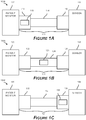
- FIGS. 1A-1C depict block diagrams of patient monitoring systems (100A, 100B, 100C) including a medical cable assembly (111, 121, 131) with an authentication circuit (115, 125, 135).
- patient monitoring system 100A includes a patient monitor 110 for receiving, processing, displaying, or otherwise interacting with data including information relating to one or more physiological parameters of a patient.
- the patient monitor includes a display screen for visually communicating information relating to a patient and/or the patient monitoring system 100A to a user.
- the system 100A includes a medical cable 111 that has a monitor connector 112 that allows the patient monitor to communicate with the medical cable assembly 111.
- Monitor connector 112 may include a housing containing one or more structures or devices.
- the medical cable assembly 111 may allow for data and/or power communication using one or more wires and/or conductors that traverse at least a portion of a longitudinal axis of a body of the medical cable assembly 114.
- the medical cable assembly 111 may further include a sensor connector 116 that allows a sensor 118 to communicate with the medical cable assembly 111.
- FIGS. 7B and 7D It may be desirable for parameter data to be provided to more than one monitor device.
- cable assembly 111 may include more than one monitor connector.
- the cable assembly 111 or the sensor 118 can include a circuit to convert a sensor signal to a digital signal to reduce the risk or effect of signal loss or corruption when splitting to multiple monitors or for any other purpose.
- the sensor 118 may be a digital sensor, an analog sensor, or a combination digital and analog sensor. Sensor 118 may be configured to detect one or more physiological parameters related to a patient and transmit a signal based at least partly on such parameters to the patient monitor 110, via medical cable assembly 111.
- sensor 118 may be a transducer configured to convert physiological information into an electrical signal that can be transmitted and/or processed by a patient monitoring system to measure one or more physiological parameters.
- sensor 118 comprises a pressure transducer for detecting blood pressure.
- the sensor 118 is configured to detect one or more of the following parameters: blood pressure, heart rate, blood-oxygenation level, or another physiological parameter.
- sensor 118 may include a pressure cuff or catheter for detecting blood pressure in a patient. More generally, the sensor 118 can be a noninvasive, invasive, or minimally-invasive sensor.
- a catheter may be inserted into a patient's circulatory system with the end of the catheter having an opening to the blood stream, typically in a major or peripheral blood vessel.
- a needle is inserted into a peripheral blood vessel.
- the needle may be inserted into the radial artery.
- the needle may be inserted into the antecubital, radial, jugular, or subclavian veins.
- a special catheter is threaded through the needle and into the blood vessel until the tip of the catheter is positioned at the particular point within the body at which it is desired to make the blood pressure measurement. Then, with the catheter in place, the needle may be withdrawn.
- An I.V. set attaches to the proximal end of the catheter protruding from the patient so that a solution flows through the catheter and into the patient.
- the I.V. solution provides a fluid "column" through which pressure pulses are transmitted, and a pressure transducer positioned along the fluid column monitors those pressure pulses.
- the pressure transducer consists of a dome that functions as a reservoir for the I.V. fluid.
- the dome includes a resilient diaphragm that attaches to an electrical transducer. The transducer senses pressure fluctuations in the diaphragm and converts them into electrical signals which then transmit through a cable to a monitor for amplification and display.
- a single silicon chip can comprise both the pressure diaphragm and the measuring circuitry of the pressure transducer. Since such silicon chips can be relatively cheaply mass-produced, the total cost of pressure transducers is reduced to the extent that the transducer becomes economically disposable.
- the cable includes a connector so that the transducer and associated portion of the cable can be discarded after use, whereas the mating connector and cable hard-wired to the monitor can be reused.
- Such disposable blood pressure transducers are the standard of care in the OR, ICU or CCU.
- the patient monitoring system 100A of FIG. 1A also includes a cable authentication module 115.
- the cable authentication module 115 is disposed at least partially within, or connected to, monitor connector 112, such as within a housing of the monitor connector.
- the patient monitor 110 is configured to communicate with cable authentication module 115.
- the patient monitor 110 may send a test signal that is received by cable authentication module 115, and receive a corresponding signal from cable authentication module 115 relating to whether medical cable assembly 111 is an expected, or authentic / compatible cable. Communication between the medical cable assembly 111 and the patient monitor 110 may comprise an analog or digital handshake or partial handshake between the two devices.
- Portions of cable authentication module 115 may be located at various distinct locations of the cable. For example, portions of the cable authentication module 115 can be located in one or both of the connectors 112, 116 and/or the cable body 114. The authentication module may instead be entirely contained within a single region of the medical cable assembly 111, for example, as shown in FIGS. 1A-1C .
- the patient monitoring system 100A may be configured such that the patient monitor 110 communicates with cable authentication module 115 in order to confirm authenticity of the medical cable assembly 111.
- the patient monitor 110 can at least partially prohibit communication between the patient monitor 110 and medical cable assembly 111 and/or sensor 118.
- the patient monitor receives, or continues to receive, a signal from the medical cable assembly 111, but outputs an error message of some kind to indicate the incompatibility.
- cable authentication module 125 is at least partially disposed within, or connected or in proximity to, a body portion 124 of medical cable assembly 121.
- a rigid housing may be attached to a portion of the cable body 127 such that one or more wires disposed within an outer sheath of the cable body 127 can communicate with one or more devices disposed at least partially within the housing.
- Such devices may include discrete circuit components and/or IC chips disposed, for example, on a circuit board or other substrate.
- the patient monitor 120 may communicate with cable authentication module 125 over one or more conductive wires running between the cable authentication module 125 and the patient monitor 120.
- Cable authentication module 125 may be located at, or in proximity to, any suitable location or position along the cable body 124. In certain embodiments, cable authentication module 125 is disposed at or near a portion of the cable body that is relatively close to the monitor connector 122. In certain embodiments, cable authentication module 125 may be disposed at or near a portion of the cable relatively close to a sensor connector 126 that is configured to be connectable to a sensor 128. The sensor connector 126 may be located at or near a distal end of cable body 124 with respect to the monitor connector 122.
- cable authentication module 135 is at least partially disposed within, or connected or in proximity to, sensor connector 136.
- sensor connector 136 may include a rigid housing such that one or more wires disposed within the housing can communicate with one or more devices disposed at least partially within the housing.
- Such devices may include discrete circuit components and/or IC chips disposed, for example, on a circuit board or other substrate.
- a patient monitoring system similar to those discussed above may include at least a portion of an authentication circuit in a sensor as opposed to, or in addition to, an authentication circuit disposed within, or connected to, a medical cable. Furthermore, at least a portion of an authentication circuit could be included in a patient monitor instead of, or in addition to, other locations in a patient monitoring system.
- FIG. 2 depicts a schematic diagram of an embodiment of an electronic circuit 205 that may be used in certain embodiments disclosed herein.
- the electronic circuit 205 may be disposed in or connected to a portion of any of the medical cable assemblies described above.
- the electronic circuit 205 receives one or more electrical signals at a header portion 220, or at switch module 230, which are identified, for convenience only, as +5 SW, +EXC, +SIG, -SIG, and -EXC.
- +EXC may refer to a positive test voltage signal or excitation signal from a patient monitor
- -EXC may refer to a common potential line
- +SIG and -SIG may refer to signal lines (e.g., differential lines) for sending a signal from the sensor to the monitor.
- signals are received via electrical connecting pins in contact with one or more wires.
- Conductive paths 1, 2, 3, 4, and 5 allow for transmission of signals between an optional switch module 230 and header module 220.
- switch module 230 includes a safety switch 235 in series between conductive paths 1 and 2.
- the switch module may be connected to a sensor, wherein connecting the switch module 230 to the sensor can cause the switch 235 to be closed and/or disconnecting the switch module 230 from the sensor can cause the switch 235 to be opened.
- switch module 230 receives an electronic signal on conductive path 2, such as a direct-current voltage signal, and redirects at least a portion of the signal towards header module 220 via conductive path 1 when switch 235 is in a closed state.
- switch 235 is in an open state, as depicted in FIG. 2 , substantially none of the signal on line 2 is redirected to line 1 in one embodiment.
- the safety switch 235 acts as a safety mechanism to at least partially prevent the patient monitor from picking up or reading invalid measurements when a sensor is not connected or is connected improperly. The safety switch 235 can therefore reduce the risk that an incorrect evaluation of a patient's health will be made due to erroneous measurements.
- the switch 235 when a sensor is not connected or is not properly connected to the electronic circuit 205, the switch 235 is in an open state. In this open state, the safety switch 235 can prevent power from being provided to an authentication circuit (see, e.g., FIGURE 4 ). In another embodiment, the safety switch 235 prevents or at least partially prevents measurement current from being transmitted by the medical cable assembly to a patient monitor when in an open state. The safety switch 235 closes in one embodiment when a sensor is properly connected to the switch 235, thereby allowing power or current to pass to an authentication circuit (see FIGURE 4 ).
- the switch 235 may be a contact switch (such as a pushbutton switch), a rocker switch, or another type of switch.
- the switch 235 can be a semiconductor switch in some embodiments, such as a diode, transistor or MOSFET, or any combination of the same. Accordingly, the switch 235 can high-enabled or low-enabled. In a low-enabled state, the switch 235 can allow power or current to be provided to an authentication circuit disposed in the cable when the switch 235 is open.
- a voltage signal +EXC is received by the connector 236 and transmitted along conductive path 2.
- the signal is further redirected within the switch module 235 and output.
- Such signal identified by reference +5 SW in FIG. 2 , may be provided to an authentication module to facilitate the functionality thereof.
- the electronic circuit 205 may further relay one or more signals (e.g., +EXC, +SIG, -SIG, -EXC), or modified versions thereof, to or from a sensor.
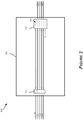
- FIG. 3 depicts a block diagram of an embodiment of an authentication module or circuit 310 for use in connection with a medical cable in a patient monitoring system, such as any of the cables and systems described herein.
- the depicted embodiment of the authentication circuit 310 includes an input port 340 and an output port 330. In certain embodiments, both input 340 and output ports 330 may be connected to a patient monitor (not shown). Further, authentication circuit 310 may include one or more additional ports that may be, for example, connected to a patient sensor, or elsewhere.
- the authentication circuit 310 can include a constant current source 320 and a capacitor C1, in addition to possibly other devices or components (as described below). In certain embodiments, authentication circuit 310 provides a signal to the monitor that can enable the monitor to determine whether the cable containing the authentication circuit 310 is a valid cable.
- the authentication circuit 310 can provide a ramp voltage signal to the output port 330, wherein the voltage of the signal reaches a certain value at after a period of time expected by the monitor.
- the ramp signal can have a linear slope or the like.
- the ramp signal is a sawtooth waveform, or at least one period of a sawtooth waveform, or a portion thereof.
- the ramp signal is a reverse sawtooth waveform, or a portion thereof.
- the ramp signal is at least a portion of a triangle waveform.
- the ramp signal may or may not be periodic.
- the authentication circuit 310 receives a voltage signal from a patient monitor via input 340.
- the authentication circuit 310 may use at least a portion of the voltage signal to drive a constant current source, which, in turn, provides a substantially constant current to capacitor C1. Charging a capacitor with a constant current can produce a linearly increasing voltage across the capacitor over time because the capacitor can integrate the constant input to produce a ramp output.
- the output of the authentication circuit 310 to the output port 330 can be in electrical communication with the capacitor, such that the output signal is based on the voltage across the capacitor C1. Therefore, the output port 330 may provide a ramp signal to the patient monitor.
- the current source 320 and/or capacitor C1 may be substituted or supplemented with one or more other components or devices configured to receive a signal from the monitor and produce a ramp voltage signal, such as a ramp signal having predetermined response characteristics.
- the authentication circuit 310 may include a transimpedance amplifier connected to the current source 320 to convert the current output from current source 320 into a voltage output. Further, output from the transimpedance amplifier may be supplied to an integrator circuit instead of, or in addition to, a capacitor. The output from the integrator circuit may provide a ramp voltage signal suitable for certain patient monitor authentication testing.
- input 340 is provided to an integrator circuit, instead of to current source 320 and capacitor C1, which may provide a suitable ramp voltage output.
- the authentication circuit 310 may include one or more timer circuits, such as a multivibrator circuit (e.g., a 555 or 556 timer), in addition to, or in place of components shown in FIG. 3 , which are configured to provide desirable output signals expected by the patient monitor.
- a multivibrator circuit e.g., a 555 or 556 timer
- circuit components that may be included in authentication circuit 310 in place of, or in addition to, one or more other components described herein include one or more function generator circuits, oscillator circuits, resistor networks (such as a resistor ladder), a processor that outputs a ramp or other suitable waveform, or other circuit configured to provide a desirable output signal for purposes of demonstrating authenticity or compatibility of a medical cable assembly.
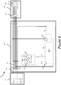
- FIG. 4 illustrates a schematic diagram of an embodiment of a patient monitoring system 400 having a medical cable authentication circuit 420.
- the circuit in FIG. 4 is identified in three regions: a patient monitor circuit 410, an authentication circuit 420, and a switch circuit 430.
- circuitry described in connection with FIG. 4 can be located in any of the depicted regions, or in any suitable location in the patient monitoring system 400.
- the patient monitor circuit 410 includes a transistor T1, the base or gate of which is connected in parallel to a resistor R1 and a switch S2.
- the patient monitor (not shown), such as the 110 may be configured to provide a test signal, such as a direct-current voltage signal, or pulse signal, to connector 422, for example, a 4.2-Volt DC signal, a 5 V signal, or some other voltage value.
- the test signal from the patient monitor may be transmitted within the cable circuit along conductive path 402. At least a portion of the test signal may be directed to the switch circuit 430 and pass through a connector or header portion 432 and enter switch module 434.
- Switch module 430 as described above with respect to FIG.
- conductive line 404 is tied to a common potential, which may be a ground potential
- the switch S1 when the switch S1 is in a closed state, the switch passes power to the cable circuit 420, allowing the authentication circuit 420 to authenticate the cable. In an open state, the switch S1 prevents or substantially prevents power from reaching the authentication circuit 420, thereby preventing the cable from authenticating to the monitor. As a result, the switch S1 can at least partially prevent the monitor from outputting measurements in response to detecting the authentication of the cable when a sensor is not present or not properly connected.
- the test signal drives a current source 424.
- the current source 424 is optionally programmable.
- the current source 424 may be an integrated circuit.
- current source may be a 2-terminal programmable current source, such as, for example, the model LT3092 current source manufactured by Linear Technology Corporation of Milpitas, CA. See LT3092 Datasheet, available at http://cds.linear.com/docs/Datasheet/3092fb.pdf (hereinafter, "the LT3092 datasheet").
- the current source 424 can include at least an internal current source 425, an amplifier 427, and transistors T2 and T3, which are configured to amplify the current of current source 425.
- current source 425 is an approximately 10 ⁇ A source, and the amplification provided by the programmable current source 424 is based on the values of resistor R2 and R3 connected thereto, wherein the current source produced current in the range of, for example, about 1-5 mA, or about 0.1 mA to about 10 mA, or some other value.
- the current source 424 may output a substantially constant current that the capacitor C1 converts into a ramp signal.
- Line 401 of the authentication circuit 420 may be connected to an input pin (pin 3) of the current source 424.
- the resistor R2 may be connected to a SET pin (pin 1), while resistor R3 may be connected to output pins (pins 2 and 4) of the current source 424.
- the R2 resistor is referred to as "R SET” and the R3 resistor is referred to as "R OUT ". See id., p. 8.
- the resistors R2 and R3 can tune the current source 424 to program the value of the output current.
- I SOURCE is the output current.
- R1 13.0 k ⁇ and R2 being 100 ⁇
- the current supplied from Node A to the capacitor can therefore be, in some embodiments, about 1.30 mA.
- resistor R2 has a value in the range of approximately 2 to 5 K Ohms, or between 11 K Ohms and 17 K Ohms.
- R2 may have a value of approximately 2.1 K Ohms or 4.2 K Ohms in order to produce a desirable output signal.
- R2 has a value of approximately 13 K Ohms.
- capacitor C1 may have a value of approximately .01 ⁇ F to .09 ⁇ F.
- C1 may have a value of approximately .082 ⁇ F or .085 ⁇ F in order to produce a desirable output signal.
- capacitor C1 may have a value of around .1 ⁇ F or more, or any value in a range of about 0.05 ⁇ F to about 0.15 ⁇ F, or some other range.
- capacitor values may vary substantially from system to system, and such values are provided herein as examples only. Any suitable value may be implemented in accordance with embodiments disclosed herein.
- Adequacy of the output signal of authentication circuit 420 may be measured by the amount of time the authentication circuit 420 takes to produce one or more suitable output voltage signals in response to receiving an input test signal. For example, it may be desirable for an input voltage signal to reach a target voltage level or have a pulse width within a predefined range.
- the target time in which the target voltage level is reached can be any period of time. However, some examples of time periods include about 100 ⁇ S to about 200 ⁇ S, or about 500 nS to about 50 ⁇ S, or about 50 ⁇ S to about 300 ⁇ S, or about 300 ⁇ S to about 1 mS, or about 1mS to about 100 mS.
- a desirable pulse width is in the range of 80 ⁇ S to 160 ⁇ S.
- the desirable pulse width may be 110, 135, 138, or 150 ⁇ S, or another value.
- the capacitance value of C1 and/or the resistance value of R2 may be manipulated to achieve a desirable pulse width as described above.
- the authentication circuit 420 includes a buffer amplifier 429, which may be connected to one or more resisters R4, R5. In other embodiments, the buffer amplifier 429 and/or one or more of resistors R4 and R5 can be omitted from the authentication circuit 420. However, the buffer amplifier 429 can reduce any loading by the monitor circuit 410 on the authentication circuit 420.
- Authentication circuit 420 may also include a clamping diode D1, which can shift the DC value of the output signal of the buffer amplifier 429.
- the diode D1 may be configured such that an approximately 100 mV to 300 mV drop appears across the diode D1, or about a 100 mV to 600 mV drop.
- diodes having values greater or less than such range may be incorporate as desirable, or suitable in the system 400.
- the diode D1 may be configured to discharge, or drain voltage on the capacitor C1, such as between test cycles of the patient monitoring system 400.
- the diode D1 is a Schottky diode, although other types of diodes can be used in place of a Schottky diode, In certain embodiments diode D1 is replaced by, for example, an operational amplifier or other device through which capacitor C1 can discharge. In certain embodiments, the diode D1 and/or the conductive branch on which it lies may be omitted from authentication circuit 420. Various other components may be omitted from authentication circuit 420, such as, for example, resistors R2, R3, and R4.
- the buffer amplifier 429 has a unity gain or approximately unity gain. Therefore, the authentication circuit 420 effectively outputs the ramp signal generated by the current source 424 and capacitor C1, and clamped by diode D1, to the patient monitor circuit 410.
- the buffer amplifier can have a gain other than unity in some embodiments.
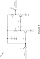
- FIG. 5 provides a schematic diagram of an example not describing part of the present invention of an authentication circuit 500 for use in connection with a medical cable in a patient monitoring system.
- authentication circuit 500 can be used in place of authentication circuit 420 described above with reference to FIG. 4 .
- the authentication circuit 500 includes an input port 510 for receiving an electronic signal.
- the authentication circuit may receive a test signal, such as, e.g., a direct-current voltage signal, from a patient monitor or other device.
- the authentication circuit 500 may be configured to generate an output signal to output port 520 based at least in part on the input signal.
- the output signal is an exponential voltage signal.
- the authentication circuit 500 includes three resistors R1, R2, R3, and a capacitor C1 in a parallel configuration with respect to the input port 510.
- a transistor such as, for example, a bi-polar junction transistor (BJT) is connected at its base to resistor R1 and at its collector to the parallel branches of resistor R2 and capacitor C2.
- Resistors R1 and R2 may serve to bias transistor Transistor T2 is connected at its base to resistor R3, which is in series with capacitor C2, while its collector is connected to resistor R4, and also provides the output signal to output port 520. Both transistors T1 and T2 may be tied to ground at their emitter.
- a signal is input from a patient monitor at port 510, and is subsequently passed and/or amplified by T1 to the RC pair including capacitor C2 and resistor R3, which produce an exponential output signal having an RC time constant.
- the output of the RC pair is amplified by transistor T2 to produce an output signal. Because of the amplification of the T1 and/or T2 transistors, the rise time of the output waveform can differ from the rise time of the RC circuit between T1 and T2.
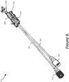
- FIG. 6 is a perspective view of an embodiment of a sensor assembly 600 for use in a patient monitoring system.
- Sensor assembly 600 may be mountable to a mounting bracket and/or support pole (not shown) for use in a patient monitoring system.
- the sensor assembly 600 includes a housing 670 and one or more cables 630, 640.
- the cables 630, 640 may extend from one end of the housing 670 and terminate at one or more electrical connectors 610, 620.
- the sensor assembly 600 may further include a stopcock assembly 680, such as a two-port stopcock assembly, as shown, at a distal end of the housing 670.
- the sensor assembly 600 has a length of about 25-35 cm. However, the sensor assembly 600 may be any suitable length.
- an internal flow channel in the stopcock assembly 680 leads to a tube 660 disposed on the housing 670 opposite a mounting plate 650.
- the mounting plate 650 may engage a mounting bracket such that the tube 660 faces outward from the mounting bracket.
- the sensor assembly 600 may be configured to be connected to various other components or devices.
- a patient monitor may include cables and/or connectors that mate with the connectors 610, 620 and receive electrical signals indicative of one or more physiological parameters, such as, e.g., blood pressure detected using the sensor assembly 600.
- a catheter disposed in contact with a fluid to be measured may attach to a port of the stopcock assembly 680.
- multiple catheters may be used for pressure monitoring.
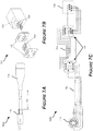
- FIG. 7A is a side view of an embodiment of a medical cable assembly 700A having a monitor connector portion 710, a cable body portion 720, and a sensor connector portion 730.
- Monitor connector 710 is configured to be connectable to a patient monitor
- sensor connector 730 is configured to be connectable to a sensor that detects one or more physiological parameters of a patient.
- Cable body 720 may allow for transmission of signals between monitor connector 710 and sensor connector 730.
- the sensor connector 730 comprises a housing containing at least a portion of one or more internal electrical components.
- FIG. 7B shows an exploded view of an embodiment of a connector assembly 732 that may be disposed at least partially within sensor connector 730.
- Connector assembly 732 may include a rigid structure 738 that, in certain embodiments, has a shape and configuration similar to that of a telephone jack.
- Rigid structure 738 may include one or more pins that are configured to couple to corresponding pins in a sensor assembly. Such pins may extend through rigid structure 738 and protrude through an outer surface of rigid structure 738.
- Such protruding pins are identified in FIG. 7B by reference number 739.
- Pins 739 may be configured, as shown, to penetrate one or more electronic circuit boards 734, such as by being threaded through holes in one or more of circuit boards 734.
- Electronic circuit boards 734 may include a medical cable authentication circuit as discussed above with respect to various embodiments.
- electronic circuit boards are configured to be placed adjacent to a rigid structure 738 in a stacked configuration, whereby pins 739 penetrate the circuit boards such that one of the circuit boards 734 is disposed in closer proximity to the surface of the rigid structure 738 than another circuit board.
- connector assembly may include a connector, or header member 736 disposed between the circuit boards 734 that includes electronic pins for electrically coupling the circuit boards 734. Header member 736 may also include a spacing structure for providing a desirable amount of space between the circuit boards 734.
- FIG. 7D provides a perspective view of an assembled connector assembly shown in FIG. 7B .
- FIG. 7C illustrates a schematic diagram of the medical cable assembly depicted in FIG. 7A.
- FIG. 7C provides alternate views of various components discussed above in connection with FIGS. 7A and 7B , such as the monitor connector 710, the cable body 720, the circuit boards 734, the header member 736, and the rigid structure 738.
- the illustrated lines connecting between the various components of the medical cable assembly demonstrate the electrical connectivity between the various components.
- FIG. 7E shows a front view of a distal end of the sensor connector portion 730 depicted in FIG. 7A and described above.
- the connector portion 730 may include a cylindrical or other-shaped outer portion 734, which encases rigid structure 738.
- the rigid structure 738 includes a cutout interior engagement cavity 734 for accepting an electrical connector.
- the cavity 734 may be the same as or similar to a cavity of a standard telephone or Ethernet jack.
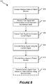
- FIG. 8 is a flow chart depicting a method 800 of authenticating a medical cable in accordance with one or more embodiments described herein.
- the method 800 may include connecting a medical cable to a patient monitor, as shown at block 802.
- a user may physically couple a medical cable to a patient monitor in any suitable manner, depending on the specifications of the system.
- a test signal is received, such as from a patient monitor.
- the test signal may comprise a square pulse wave, a constant voltage signal, or any other signal.
- the test signal is received by an authentication circuit disposed in, or connected to, the medical cable.
- the authentication circuit at least partially converts the test signal into a substantially constant current signal and, using at least a portion of such signal, generates a ramp output signal (block 808).
- the ramp signal is provided to a patient monitor, In certain embodiments, the patient monitor may determine whether the medical cable is an authenticated cable based at least in part on the ramp signal.
- a sensor signal is transmitted from the sensor to the patient monitor using the medical cable. In certain embodiments, the sensor signal may not be transmitted to the patient monitor, such as, for example, when it is determined that the medical cable is not an authenticated medical cable.
- FIG. 9 is a graph 900 of an output voltage ramp signal 910 of an embodiment of an authentication circuit over time.
- FIG. 9 also includes a capacitor voltage ramp signal 920.
- the graph of FIG. 9 may correspond, for example, to an authentication circuit 420 as described above with respect to FIG. 4 .
- the output signal 910 experiences a jump 915 in voltage of about 0.3 V at about the time when the capacitor C1 begins to be charged.
- This jump 915 may result at least in part from a clamping effect of a diode, such as diode D1, which may have a diode drop of about 0.3 V
- the diode drop can therefore result in the signal effectively being about 0.3 V instead of 0 V in one embodiment.
- this voltage jump can depend at least partly on the diode, if the value of the diode drop is other than 0.3 V, the initial voltage jump value can also be relatively higher. The value of the initial voltage may also be higher due to any voltage remaining on the capacitor from a previous test cycle. Output values provided to a patient monitor by the authentication circuit may be acceptable within a degree of tolerance. Therefore, relatively minor variations in voltage levels may not cause the output signal to fall out of acceptable ranges expected by the patient monitor for purposes of authentication of compatibility or functionality.
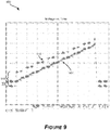
- FIG. 10 is a graph showing examples of the time it takes an output voltage signal of an embodiment of an authentication circuit to reach a target voltage with respect to a resistance value associated with the authentication circuit.
- the graph may correspond, for example, to an authentication circuit 420 as described above with respect to FIG. 4 .
- a patient monitor may accept, for purposes of authentication, voltage output levels from an authentication circuit that fall within a particular range. Accordingly, values of certain devices of the authentication circuit 420 may be modified and still fall within acceptable ranges, depending on system characteristics. For example, with the value of the capacitor C1 and resistor R3 held constant, FIG. 10 provides the time to reach a target voltage value with respect to different values of R2.
- the relevant target voltage may be, for example, a value between about 2-5 V (or some other value), plus or minus a range of tolerance.
- acceptable times for the output signal to reach the target voltage are shown as being between about 168 ⁇ S and about 104 ⁇ S. However, these values may differ significantly in some embodiments, depending on the target voltage range or based on other factors.
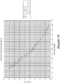
- FIG. 11 is a graph showing an example time it may take an output voltage signal of an embodiment of an authentication circuit to reach a target voltage with respect to resistance and capacitance values associated with the authentication circuit. Specifically, with the value of R3 held constant, FIG. 11 shows the time to reach a target voltage value with respect to different values of R2 and C1. It should be noted that the actual time that the linear voltage ramp takes to reach the target voltage can also vary due to component tolerances, component temperature changes, and noise in the authentication circuit, among possibly other factors.
- a machine such as a general purpose processor, a digital signal processor (DSP), an application specific integrated circuit (ASIC), a field programmable gate array (FPGA) or other programmable logic device, discrete gate or transistor logic, discrete hardware components, or any combination thereof designed to perform the functions described herein.
- DSP digital signal processor
- ASIC application specific integrated circuit
- FPGA field programmable gate array
- a general purpose processor can be a microprocessor, but in the alternative, the processor can be a controller, microcontroller, or state machine, combinations of the same, or the like.
- a processor can also be implemented as a combination of computing devices, e.g., a combination of a DSP and a microprocessor, a plurality of microprocessors, one or more microprocessors in conjunction with a DSP core, or any other such configuration. Although described herein primarily with respect to digital technology, a processor may also include primarily analog components. For example, any of the signal processing algorithms described herein may be implemented in analog circuitry.
- a computing environment can include any type of computer system, including, but not limited to, a computer system based on a microprocessor, a mainframe computer, a digital signal processor, a portable computing device, a personal organizer, a device controller, and a computational engine within an appliance, to name a few.
- a software module can reside in RAM memory, flash memory, ROM memory, EPROM memory, EEPROM memory, registers, hard disk, a removable disk, a CD-ROM, or any other form of non-transitory computer-readable storage medium, media, or physical computer storage known in the art.
- An exemplary storage medium can be coupled to the processor such that the processor can read information from, and write information to, the storage medium.
- the storage medium can be integral to the processor.
- the processor and the storage medium can reside in an ASIC.
- the ASIC can reside in a user terminal.
- the processor and the storage medium can reside as discrete components in a user terminal.
Applications Claiming Priority (2)
| Application Number | Priority Date | Filing Date | Title |
|---|---|---|---|
| US201261624970P | 2012-04-16 | 2012-04-16 | |
| PCT/US2013/032609 WO2013158314A2 (en) | 2012-04-16 | 2013-03-15 | Medical cable including authentication circuit |
Publications (3)
| Publication Number | Publication Date |
|---|---|
| EP2838421A2 EP2838421A2 (en) | 2015-02-25 |
| EP2838421A4 EP2838421A4 (en) | 2016-05-25 |
| EP2838421B1 true EP2838421B1 (en) | 2019-05-29 |
Family
ID=49384209
Family Applications (1)
| Application Number | Title | Priority Date | Filing Date |
|---|---|---|---|
| EP13778852.7A Active EP2838421B1 (en) | 2012-04-16 | 2013-03-15 | Medical cable including authentication circuit |
Country Status (6)
| Country | Link |
|---|---|
| US (1) | US9300356B2 (ja) |
| EP (1) | EP2838421B1 (ja) |
| JP (1) | JP5956061B2 (ja) |
| DK (1) | DK2838421T3 (ja) |
| ES (1) | ES2741727T3 (ja) |
| WO (1) | WO2013158314A2 (ja) |
Families Citing this family (12)
| Publication number | Priority date | Publication date | Assignee | Title |
|---|---|---|---|---|
| ES2741727T3 (es) | 2012-04-16 | 2020-02-12 | Icu Medical Inc | Cable médico que incluye circuito de autenticación |
| EP3110317B1 (en) * | 2014-02-25 | 2023-05-03 | ICU Medical, Inc. | Patient monitoring system with gatekeeper signal and corresponding method |
| US10010259B2 (en) * | 2015-05-01 | 2018-07-03 | Advancer Technologies, Llc | EMG circuit |
| AU2016341195B2 (en) | 2015-10-19 | 2019-03-14 | Icu Medical, Inc. | Hemodynamic monitoring system with detachable display unit |
| KR101977780B1 (ko) * | 2017-09-28 | 2019-05-15 | 금오기전 주식회사 | 센서 데이터 처리 시스템에서의 전기적 임피던스 측정치를 이용한 자동 설정 장치 및 방법 |
| US11179203B2 (en) * | 2017-10-26 | 2021-11-23 | Biosense Webster (Israel) Ltd. | Position-tracking-enabling connector for an ear-nose-throat (ENT) tool |
| US10290371B1 (en) * | 2018-01-30 | 2019-05-14 | General Electric Company | System of medical devices and method of controlling the same |
| WO2020146894A1 (en) * | 2019-01-13 | 2020-07-16 | Stryker Corporation | Systems and methods for connecting a medical imaging device to a medical imaging controller |
| US11871953B2 (en) | 2019-04-30 | 2024-01-16 | Stryker Corporation | Adapter and methods for coupling an ultrasonic surgical handpiece to a control console |
| US11583218B2 (en) | 2019-11-20 | 2023-02-21 | Advancer Technologies, Llc | EMG device |
| USD1015545S1 (en) | 2019-11-20 | 2024-02-20 | Advancer Technologies, Llc | Electromyography device |
| JP2022030808A (ja) * | 2020-08-07 | 2022-02-18 | キヤノン株式会社 | 受電装置、その制御方法、及びプログラム |
Citations (1)
| Publication number | Priority date | Publication date | Assignee | Title |
|---|---|---|---|---|
| US20060009699A1 (en) * | 2004-07-08 | 2006-01-12 | Luchy Roteliuk | Disposable blood pressure transducer and monitor interface |
Family Cites Families (7)
| Publication number | Priority date | Publication date | Assignee | Title |
|---|---|---|---|---|
| US6307476B1 (en) * | 1999-04-02 | 2001-10-23 | Bed-Check Corporation | Smart binary switch for use with an electronic patient monitor |
| US6308089B1 (en) * | 1999-04-14 | 2001-10-23 | O.B. Scientific, Inc. | Limited use medical probe |
| US6298255B1 (en) * | 1999-06-09 | 2001-10-02 | Aspect Medical Systems, Inc. | Smart electrophysiological sensor system with automatic authentication and validation and an interface for a smart electrophysiological sensor system |
| US6663570B2 (en) * | 2002-02-27 | 2003-12-16 | Volcano Therapeutics, Inc. | Connector for interfacing intravascular sensors to a physiology monitor |
| US7258688B1 (en) * | 2002-04-16 | 2007-08-21 | Baylis Medical Company Inc. | Computerized electrical signal generator |
| US20110057881A1 (en) * | 2009-09-04 | 2011-03-10 | Aten International Co., Ltd. | Kvm management system and method of providing adaptable synchronization signal |
| ES2741727T3 (es) | 2012-04-16 | 2020-02-12 | Icu Medical Inc | Cable médico que incluye circuito de autenticación |
-
2013
- 2013-03-15 ES ES13778852T patent/ES2741727T3/es active Active
- 2013-03-15 WO PCT/US2013/032609 patent/WO2013158314A2/en active Application Filing
- 2013-03-15 JP JP2015507014A patent/JP5956061B2/ja active Active
- 2013-03-15 EP EP13778852.7A patent/EP2838421B1/en active Active
- 2013-03-15 DK DK13778852.7T patent/DK2838421T3/da active
-
2014
- 2014-10-14 US US14/514,299 patent/US9300356B2/en active Active
Patent Citations (1)
| Publication number | Priority date | Publication date | Assignee | Title |
|---|---|---|---|---|
| US20060009699A1 (en) * | 2004-07-08 | 2006-01-12 | Luchy Roteliuk | Disposable blood pressure transducer and monitor interface |
Also Published As
| Publication number | Publication date |
|---|---|
| DK2838421T3 (da) | 2019-08-05 |
| JP5956061B2 (ja) | 2016-07-20 |
| ES2741727T3 (es) | 2020-02-12 |
| US9300356B2 (en) | 2016-03-29 |
| JP2015519928A (ja) | 2015-07-16 |
| EP2838421A4 (en) | 2016-05-25 |
| WO2013158314A3 (en) | 2015-04-30 |
| US20150155912A1 (en) | 2015-06-04 |
| EP2838421A2 (en) | 2015-02-25 |
| WO2013158314A2 (en) | 2013-10-24 |
Similar Documents
| Publication | Publication Date | Title |
|---|---|---|
| EP2838421B1 (en) | Medical cable including authentication circuit | |
| US8764668B2 (en) | Disposable blood pressure transducer and monitor interface | |
| JP6022945B2 (ja) | 身体パラメータセンサおよびモニタインターフェース | |
| JP4644425B2 (ja) | 移植可能なセンサ電極と電子回路構成 | |
| US9370322B2 (en) | Modular docking station | |
| US8550997B2 (en) | Sensor and monitor system | |
| EP2101159A2 (en) | A sensor interface | |
| JP2019500926A (ja) | センサーセット | |
| US20170188954A1 (en) | Interface unit and a measurement system | |
| JP6285966B2 (ja) | ケーブル及び受信機を生理学的モニタに接続するインターフェースの作動方法 | |
| EP2131732B1 (en) | Disposable sensor device and monitoring system | |
| JP6984069B2 (ja) | 超音波システム用延長ケーブル |
Legal Events
| Date | Code | Title | Description |
|---|---|---|---|
| PUAI | Public reference made under article 153(3) epc to a published international application that has entered the european phase |
Free format text: ORIGINAL CODE: 0009012 |
|
| 17P | Request for examination filed |
Effective date: 20141014 |
|
| AK | Designated contracting states |
Kind code of ref document: A2 Designated state(s): AL AT BE BG CH CY CZ DE DK EE ES FI FR GB GR HR HU IE IS IT LI LT LU LV MC MK MT NL NO PL PT RO RS SE SI SK SM TR |
|
| AX | Request for extension of the european patent |
Extension state: BA ME |
|
| RIN1 | Information on inventor provided before grant (corrected) |
Inventor name: WONG, KWOK-KWONG Inventor name: WINWARD, KELSEY, BRENDON Inventor name: MACDONALD, DOUGLAS, B. |
|
| R17D | Deferred search report published (corrected) |
Effective date: 20150430 |
|
| DAX | Request for extension of the european patent (deleted) | ||
| A4 | Supplementary search report drawn up and despatched |
Effective date: 20160421 |
|
| RIC1 | Information provided on ipc code assigned before grant |
Ipc: A61B 5/00 20060101ALI20160415BHEP Ipc: A61B 5/02 20060101ALI20160415BHEP Ipc: A61B 5/04 20060101AFI20160415BHEP |
|
| STAA | Information on the status of an ep patent application or granted ep patent |
Free format text: STATUS: EXAMINATION IS IN PROGRESS |
|
| 17Q | First examination report despatched |
Effective date: 20161215 |
|
| GRAP | Despatch of communication of intention to grant a patent |
Free format text: ORIGINAL CODE: EPIDOSNIGR1 |
|
| STAA | Information on the status of an ep patent application or granted ep patent |
Free format text: STATUS: GRANT OF PATENT IS INTENDED |
|
| INTG | Intention to grant announced |
Effective date: 20181022 |
|
| GRAJ | Information related to disapproval of communication of intention to grant by the applicant or resumption of examination proceedings by the epo deleted |
Free format text: ORIGINAL CODE: EPIDOSDIGR1 |
|
| STAA | Information on the status of an ep patent application or granted ep patent |
Free format text: STATUS: EXAMINATION IS IN PROGRESS |
|
| GRAR | Information related to intention to grant a patent recorded |
Free format text: ORIGINAL CODE: EPIDOSNIGR71 |
|
| GRAS | Grant fee paid |
Free format text: ORIGINAL CODE: EPIDOSNIGR3 |
|
| STAA | Information on the status of an ep patent application or granted ep patent |
Free format text: STATUS: GRANT OF PATENT IS INTENDED |
|
| INTC | Intention to grant announced (deleted) | ||
| INTG | Intention to grant announced |
Effective date: 20190319 |
|
| GRAA | (expected) grant |
Free format text: ORIGINAL CODE: 0009210 |
|
| STAA | Information on the status of an ep patent application or granted ep patent |
Free format text: STATUS: THE PATENT HAS BEEN GRANTED |
|
| AK | Designated contracting states |
Kind code of ref document: B1 Designated state(s): AL AT BE BG CH CY CZ DE DK EE ES FI FR GB GR HR HU IE IS IT LI LT LU LV MC MK MT NL NO PL PT RO RS SE SI SK SM TR |
|
| REG | Reference to a national code |
Ref country code: GB Ref legal event code: FG4D |
|
| REG | Reference to a national code |
Ref country code: CH Ref legal event code: EP |
|
| REG | Reference to a national code |
Ref country code: AT Ref legal event code: REF Ref document number: 1137776 Country of ref document: AT Kind code of ref document: T Effective date: 20190615 |
|
| REG | Reference to a national code |
Ref country code: IE Ref legal event code: FG4D |
|
| REG | Reference to a national code |
Ref country code: DE Ref legal event code: R096 Ref document number: 602013056036 Country of ref document: DE |
|
| REG | Reference to a national code |
Ref country code: DK Ref legal event code: T3 Effective date: 20190731 |
|
| REG | Reference to a national code |
Ref country code: NL Ref legal event code: FP |
|
| REG | Reference to a national code |
Ref country code: LT Ref legal event code: MG4D |
|
| PG25 | Lapsed in a contracting state [announced via postgrant information from national office to epo] |
Ref country code: PT Free format text: LAPSE BECAUSE OF FAILURE TO SUBMIT A TRANSLATION OF THE DESCRIPTION OR TO PAY THE FEE WITHIN THE PRESCRIBED TIME-LIMIT Effective date: 20190930 Ref country code: LT Free format text: LAPSE BECAUSE OF FAILURE TO SUBMIT A TRANSLATION OF THE DESCRIPTION OR TO PAY THE FEE WITHIN THE PRESCRIBED TIME-LIMIT Effective date: 20190529 Ref country code: FI Free format text: LAPSE BECAUSE OF FAILURE TO SUBMIT A TRANSLATION OF THE DESCRIPTION OR TO PAY THE FEE WITHIN THE PRESCRIBED TIME-LIMIT Effective date: 20190529 Ref country code: HR Free format text: LAPSE BECAUSE OF FAILURE TO SUBMIT A TRANSLATION OF THE DESCRIPTION OR TO PAY THE FEE WITHIN THE PRESCRIBED TIME-LIMIT Effective date: 20190529 Ref country code: NO Free format text: LAPSE BECAUSE OF FAILURE TO SUBMIT A TRANSLATION OF THE DESCRIPTION OR TO PAY THE FEE WITHIN THE PRESCRIBED TIME-LIMIT Effective date: 20190829 Ref country code: SE Free format text: LAPSE BECAUSE OF FAILURE TO SUBMIT A TRANSLATION OF THE DESCRIPTION OR TO PAY THE FEE WITHIN THE PRESCRIBED TIME-LIMIT Effective date: 20190529 Ref country code: AL Free format text: LAPSE BECAUSE OF FAILURE TO SUBMIT A TRANSLATION OF THE DESCRIPTION OR TO PAY THE FEE WITHIN THE PRESCRIBED TIME-LIMIT Effective date: 20190529 |
|
| PG25 | Lapsed in a contracting state [announced via postgrant information from national office to epo] |
Ref country code: LV Free format text: LAPSE BECAUSE OF FAILURE TO SUBMIT A TRANSLATION OF THE DESCRIPTION OR TO PAY THE FEE WITHIN THE PRESCRIBED TIME-LIMIT Effective date: 20190529 Ref country code: GR Free format text: LAPSE BECAUSE OF FAILURE TO SUBMIT A TRANSLATION OF THE DESCRIPTION OR TO PAY THE FEE WITHIN THE PRESCRIBED TIME-LIMIT Effective date: 20190830 Ref country code: RS Free format text: LAPSE BECAUSE OF FAILURE TO SUBMIT A TRANSLATION OF THE DESCRIPTION OR TO PAY THE FEE WITHIN THE PRESCRIBED TIME-LIMIT Effective date: 20190529 Ref country code: BG Free format text: LAPSE BECAUSE OF FAILURE TO SUBMIT A TRANSLATION OF THE DESCRIPTION OR TO PAY THE FEE WITHIN THE PRESCRIBED TIME-LIMIT Effective date: 20190829 |
|
| REG | Reference to a national code |
Ref country code: AT Ref legal event code: MK05 Ref document number: 1137776 Country of ref document: AT Kind code of ref document: T Effective date: 20190529 |
|
| PG25 | Lapsed in a contracting state [announced via postgrant information from national office to epo] |
Ref country code: AT Free format text: LAPSE BECAUSE OF FAILURE TO SUBMIT A TRANSLATION OF THE DESCRIPTION OR TO PAY THE FEE WITHIN THE PRESCRIBED TIME-LIMIT Effective date: 20190529 Ref country code: RO Free format text: LAPSE BECAUSE OF FAILURE TO SUBMIT A TRANSLATION OF THE DESCRIPTION OR TO PAY THE FEE WITHIN THE PRESCRIBED TIME-LIMIT Effective date: 20190529 Ref country code: CZ Free format text: LAPSE BECAUSE OF FAILURE TO SUBMIT A TRANSLATION OF THE DESCRIPTION OR TO PAY THE FEE WITHIN THE PRESCRIBED TIME-LIMIT Effective date: 20190529 Ref country code: SK Free format text: LAPSE BECAUSE OF FAILURE TO SUBMIT A TRANSLATION OF THE DESCRIPTION OR TO PAY THE FEE WITHIN THE PRESCRIBED TIME-LIMIT Effective date: 20190529 Ref country code: EE Free format text: LAPSE BECAUSE OF FAILURE TO SUBMIT A TRANSLATION OF THE DESCRIPTION OR TO PAY THE FEE WITHIN THE PRESCRIBED TIME-LIMIT Effective date: 20190529 |
|
| REG | Reference to a national code |
Ref country code: ES Ref legal event code: FG2A Ref document number: 2741727 Country of ref document: ES Kind code of ref document: T3 Effective date: 20200212 |
|
| PG25 | Lapsed in a contracting state [announced via postgrant information from national office to epo] |
Ref country code: SM Free format text: LAPSE BECAUSE OF FAILURE TO SUBMIT A TRANSLATION OF THE DESCRIPTION OR TO PAY THE FEE WITHIN THE PRESCRIBED TIME-LIMIT Effective date: 20190529 |
|
| REG | Reference to a national code |
Ref country code: DE Ref legal event code: R097 Ref document number: 602013056036 Country of ref document: DE |
|
| PG25 | Lapsed in a contracting state [announced via postgrant information from national office to epo] |
Ref country code: TR Free format text: LAPSE BECAUSE OF FAILURE TO SUBMIT A TRANSLATION OF THE DESCRIPTION OR TO PAY THE FEE WITHIN THE PRESCRIBED TIME-LIMIT Effective date: 20190529 |
|
| PLBE | No opposition filed within time limit |
Free format text: ORIGINAL CODE: 0009261 |
|
| STAA | Information on the status of an ep patent application or granted ep patent |
Free format text: STATUS: NO OPPOSITION FILED WITHIN TIME LIMIT |
|
| PG25 | Lapsed in a contracting state [announced via postgrant information from national office to epo] |
Ref country code: PL Free format text: LAPSE BECAUSE OF FAILURE TO SUBMIT A TRANSLATION OF THE DESCRIPTION OR TO PAY THE FEE WITHIN THE PRESCRIBED TIME-LIMIT Effective date: 20190529 |
|
| 26N | No opposition filed |
Effective date: 20200303 |
|
| PG25 | Lapsed in a contracting state [announced via postgrant information from national office to epo] |
Ref country code: SI Free format text: LAPSE BECAUSE OF FAILURE TO SUBMIT A TRANSLATION OF THE DESCRIPTION OR TO PAY THE FEE WITHIN THE PRESCRIBED TIME-LIMIT Effective date: 20190529 |
|
| PG25 | Lapsed in a contracting state [announced via postgrant information from national office to epo] |
Ref country code: MC Free format text: LAPSE BECAUSE OF FAILURE TO SUBMIT A TRANSLATION OF THE DESCRIPTION OR TO PAY THE FEE WITHIN THE PRESCRIBED TIME-LIMIT Effective date: 20190529 |
|
| REG | Reference to a national code |
Ref country code: CH Ref legal event code: PL |
|
| REG | Reference to a national code |
Ref country code: DE Ref legal event code: R079 Ref document number: 602013056036 Country of ref document: DE Free format text: PREVIOUS MAIN CLASS: A61B0005040000 Ipc: A61B0005240000 |
|
| PG25 | Lapsed in a contracting state [announced via postgrant information from national office to epo] |
Ref country code: LU Free format text: LAPSE BECAUSE OF NON-PAYMENT OF DUE FEES Effective date: 20200315 |
|
| PG25 | Lapsed in a contracting state [announced via postgrant information from national office to epo] |
Ref country code: CH Free format text: LAPSE BECAUSE OF NON-PAYMENT OF DUE FEES Effective date: 20200331 Ref country code: LI Free format text: LAPSE BECAUSE OF NON-PAYMENT OF DUE FEES Effective date: 20200331 Ref country code: IE Free format text: LAPSE BECAUSE OF NON-PAYMENT OF DUE FEES Effective date: 20200315 |
|
| PG25 | Lapsed in a contracting state [announced via postgrant information from national office to epo] |
Ref country code: MT Free format text: LAPSE BECAUSE OF FAILURE TO SUBMIT A TRANSLATION OF THE DESCRIPTION OR TO PAY THE FEE WITHIN THE PRESCRIBED TIME-LIMIT Effective date: 20190529 Ref country code: CY Free format text: LAPSE BECAUSE OF FAILURE TO SUBMIT A TRANSLATION OF THE DESCRIPTION OR TO PAY THE FEE WITHIN THE PRESCRIBED TIME-LIMIT Effective date: 20190529 |
|
| PG25 | Lapsed in a contracting state [announced via postgrant information from national office to epo] |
Ref country code: MK Free format text: LAPSE BECAUSE OF FAILURE TO SUBMIT A TRANSLATION OF THE DESCRIPTION OR TO PAY THE FEE WITHIN THE PRESCRIBED TIME-LIMIT Effective date: 20190529 Ref country code: IS Free format text: LAPSE BECAUSE OF FAILURE TO SUBMIT A TRANSLATION OF THE DESCRIPTION OR TO PAY THE FEE WITHIN THE PRESCRIBED TIME-LIMIT Effective date: 20190929 |
|
| PGFP | Annual fee paid to national office [announced via postgrant information from national office to epo] |
Ref country code: DK Payment date: 20230314 Year of fee payment: 11 |
|
| PGFP | Annual fee paid to national office [announced via postgrant information from national office to epo] |
Ref country code: IT Payment date: 20230213 Year of fee payment: 11 Ref country code: GB Payment date: 20230119 Year of fee payment: 11 Ref country code: DE Payment date: 20230117 Year of fee payment: 11 Ref country code: BE Payment date: 20230216 Year of fee payment: 11 |
|
| P01 | Opt-out of the competence of the unified patent court (upc) registered |
Effective date: 20230530 |
|
| PGFP | Annual fee paid to national office [announced via postgrant information from national office to epo] |
Ref country code: ES Payment date: 20230406 Year of fee payment: 11 |
|
| PGFP | Annual fee paid to national office [announced via postgrant information from national office to epo] |
Ref country code: FR Payment date: 20231229 Year of fee payment: 12 |
|
| PGFP | Annual fee paid to national office [announced via postgrant information from national office to epo] |
Ref country code: NL Payment date: 20240108 Year of fee payment: 12 |
|
| PGFP | Annual fee paid to national office [announced via postgrant information from national office to epo] |
Ref country code: DE Payment date: 20231229 Year of fee payment: 12 Ref country code: GB Payment date: 20240108 Year of fee payment: 12 |