EP2837854A1 - Gasket - Google Patents
Gasket Download PDFInfo
- Publication number
- EP2837854A1 EP2837854A1 EP12874358.0A EP12874358A EP2837854A1 EP 2837854 A1 EP2837854 A1 EP 2837854A1 EP 12874358 A EP12874358 A EP 12874358A EP 2837854 A1 EP2837854 A1 EP 2837854A1
- Authority
- EP
- European Patent Office
- Prior art keywords
- gasket
- support protrusion
- body section
- protrusion
- mounting groove
- Prior art date
- Legal status (The legal status is an assumption and is not a legal conclusion. Google has not performed a legal analysis and makes no representation as to the accuracy of the status listed.)
- Granted
Links
Images


Classifications
-
- H—ELECTRICITY
- H05—ELECTRIC TECHNIQUES NOT OTHERWISE PROVIDED FOR
- H05K—PRINTED CIRCUITS; CASINGS OR CONSTRUCTIONAL DETAILS OF ELECTRIC APPARATUS; MANUFACTURE OF ASSEMBLAGES OF ELECTRICAL COMPONENTS
- H05K5/00—Casings, cabinets or drawers for electric apparatus
- H05K5/06—Hermetically-sealed casings
-
- F—MECHANICAL ENGINEERING; LIGHTING; HEATING; WEAPONS; BLASTING
- F16—ENGINEERING ELEMENTS AND UNITS; GENERAL MEASURES FOR PRODUCING AND MAINTAINING EFFECTIVE FUNCTIONING OF MACHINES OR INSTALLATIONS; THERMAL INSULATION IN GENERAL
- F16J—PISTONS; CYLINDERS; SEALINGS
- F16J15/00—Sealings
- F16J15/02—Sealings between relatively-stationary surfaces
- F16J15/021—Sealings between relatively-stationary surfaces with elastic packing
- F16J15/022—Sealings between relatively-stationary surfaces with elastic packing characterised by structure or material
- F16J15/024—Sealings between relatively-stationary surfaces with elastic packing characterised by structure or material the packing being locally weakened in order to increase elasticity
- F16J15/025—Sealings between relatively-stationary surfaces with elastic packing characterised by structure or material the packing being locally weakened in order to increase elasticity and with at least one flexible lip
-
- F—MECHANICAL ENGINEERING; LIGHTING; HEATING; WEAPONS; BLASTING
- F16—ENGINEERING ELEMENTS AND UNITS; GENERAL MEASURES FOR PRODUCING AND MAINTAINING EFFECTIVE FUNCTIONING OF MACHINES OR INSTALLATIONS; THERMAL INSULATION IN GENERAL
- F16J—PISTONS; CYLINDERS; SEALINGS
- F16J15/00—Sealings
- F16J15/02—Sealings between relatively-stationary surfaces
- F16J15/06—Sealings between relatively-stationary surfaces with solid packing compressed between sealing surfaces
- F16J15/10—Sealings between relatively-stationary surfaces with solid packing compressed between sealing surfaces with non-metallic packing
- F16J15/104—Sealings between relatively-stationary surfaces with solid packing compressed between sealing surfaces with non-metallic packing characterised by structure
-
- H—ELECTRICITY
- H05—ELECTRIC TECHNIQUES NOT OTHERWISE PROVIDED FOR
- H05K—PRINTED CIRCUITS; CASINGS OR CONSTRUCTIONAL DETAILS OF ELECTRIC APPARATUS; MANUFACTURE OF ASSEMBLAGES OF ELECTRICAL COMPONENTS
- H05K5/00—Casings, cabinets or drawers for electric apparatus
- H05K5/06—Hermetically-sealed casings
- H05K5/061—Hermetically-sealed casings sealed by a gasket held between a removable cover and a body, e.g. O-ring, packing
-
- B—PERFORMING OPERATIONS; TRANSPORTING
- B65—CONVEYING; PACKING; STORING; HANDLING THIN OR FILAMENTARY MATERIAL
- B65D—CONTAINERS FOR STORAGE OR TRANSPORT OF ARTICLES OR MATERIALS, e.g. BAGS, BARRELS, BOTTLES, BOXES, CANS, CARTONS, CRATES, DRUMS, JARS, TANKS, HOPPERS, FORWARDING CONTAINERS; ACCESSORIES, CLOSURES, OR FITTINGS THEREFOR; PACKAGING ELEMENTS; PACKAGES
- B65D53/00—Sealing or packing elements; Sealings formed by liquid or plastics material
- B65D53/02—Collars or rings
-
- F—MECHANICAL ENGINEERING; LIGHTING; HEATING; WEAPONS; BLASTING
- F16—ENGINEERING ELEMENTS AND UNITS; GENERAL MEASURES FOR PRODUCING AND MAINTAINING EFFECTIVE FUNCTIONING OF MACHINES OR INSTALLATIONS; THERMAL INSULATION IN GENERAL
- F16J—PISTONS; CYLINDERS; SEALINGS
- F16J15/00—Sealings
- F16J15/02—Sealings between relatively-stationary surfaces
- F16J15/06—Sealings between relatively-stationary surfaces with solid packing compressed between sealing surfaces
- F16J15/062—Sealings between relatively-stationary surfaces with solid packing compressed between sealing surfaces characterised by the geometry of the seat
Definitions
- the present invention relates to a gasket.
- the present invention relates to a gasket for a case, which is made of a low rigidity material such as synthetic resins, aluminum or the like, and is used for electronic apparatuses or the like.
- a gasket having a low reaction force and having a low change rate of the reaction force to the compression amount has been conventionally, mainly used.
- the gasket has been adopted from the viewpoint of preventing deformation of a cover and securing sealing ability to the variation of dimensional accuracy (following the partial variation of the compression amount) at the time of fastening.
- the gasket includes a body section 310 which is inserted in a mounting groove not illustrated, two lines of support protrusions 320 and 330, which are provided on the bottom side of the mounting groove of the body section 310 and extend in parallel with the body section 310, and a lip ridge protrusion 340 which is provided on the other side of the body section 310.
- the gasket includes an aperture 350 formed so as to have a shape capable of absorbing the compression of a rubber-like elastic material, on the bottom side of a mounting groove on the surface opposed to the lip ridge protrusion 340.
- the gasket 300 is not a satisfactory gasket for low reaction force with respect to a case, which is made of a low rigidity material such as synthetic resins, aluminum or the like and is used for electronic apparatuses or the like.
- Patent Document 2 a gasket 300 having a shape illustrated in Fig. 6 has been proposed.
- the gasket 300 is constituted with a body section 310 inserted in a mounting groove 100 of a case (one member) 100, and a lip ridge protrusion 340 provided on another side of the body section 310.
- the lip ridge protrusion 340 has a shape extending in a tilted manner toward the body section 310.
- the lip ridge protrusion 340 having a structure in a tilted manner, when the gasket 300 is formed and released, the lip ridge protrusion 340 is removed forcibly. Therefore, if the lip ridge protrusion 340 has a steeply tilted shape, there are problems that the lip ridge protrusion 340 is damaged easily so that the operability is low, or the like.
- the tilted angle of the lip ridge protrusion 340 is small, low reaction force is hardly made even if the lip ridge protrusion 340 falls, and the change of reaction force to the compression amount increases.
- the lip ridge protrusion 340to hardly falls in the fixed direction as planned, and there is a possibility that the lip ridge protrusion 340 may partially fall in the opposite direction. As a result, lowering the sealing ability is caused.
- the purpose of the present invention is to provide a gasket which can be easily formed, can be compressed largely at low reaction force, and is highly reliable.
- a gasket made of a rubber-like elastic material is mounted in a mounting groove provided in one of two opposing members and is gripped between the one member and the other member so as to be in pressure contact with the two members.
- the gasket is provided with: a body section which is inserted in the mounting groove; one support protrusion, which is provided on one end side of the body section in the width direction so as to be located on the bottom side of the mounting groove, and is mounted in a deep groove provided in a part of the bottom; the other support protrusion which extends in a tilted manner from the other end side, in the width direction, of the body section toward the bottom in the direction away from the one support protrusion; and a lip ridge protrusion, which is provided on the side of the body section which faces the other member, and is located so that the tip thereof does not overlap the one support protrusion of the body section.
- the body section is displaced so as to tilt on the other support protrusion
- the present invention has the effects described below.
- the gasket can be easily formed, can be easily formed, can be compressed largely at low reaction force, and is highly reliable.
- the gasket can be compressed largely at low reaction force, and attitude stability of the gasket after being inserted is proper.
- the gasket can be easily, certainly mounted in the mounting groove.
- the gasket can be easily inserted in the mounting groove, and it can be prevented more certainly that the gasket falls on the inner peripheral side of the mounting groove.
- the gasket can be compressed largely by further lower reaction force and is further highly reliable.
- a gasket as a first embodiment according to the present invention is a gasket 3 made of a rubber-like elastic material. As illustrated in Figs. 1, 2 and 3 , the gasket 3 is mounted in a mounting groove 11 provided in one of two opposing members 1 and 2 and is gripped between the one member 1 and the other member 2 so as to be in pressure contact with the two members 1 and 2.
- the gasket 3 is provided with: a body section 31 which is inserted in the mounting groove 11; one support protrusion 33, which is provided on one end side 312 of the body section 31 in the width direction so as to be located on the bottom 111 side of the mounting groove 11, and is mounted in a deep groove 112 provided in a part of the bottom 111; the other support protrusion 32 which extends in a tilted manner from the other end side 313, in the width direction, of the body section 31 toward the bottom 111 in the direction away from the one support protrusion 33; a lip ridge protrusion 34 being provided on the side of the body section 31 facing the other member 2, and being located so that the tip 343 thereof does not overlap the one support protrusion 33 of the body section 31.
- the tilted angle of the other support protrusion 32 with respect to the bottom 111 is within a range from 15 to 45 degrees. If the tilted angle is smaller than 15 decrees, a proper sealing surface pressure cannot be obtained. If the tilted angle is larger than 45 degrees, the other support protrusion 32 is removed forcibly at the time of forming and releasing. Therefore, if the other support protrusion 32 has a steeply tilted shape, there are problems that the other support protrusion 32 is damaged easily so that the operability is low, or the like.
- the lip ridge portion 34 is formed so as to be upright to the bottom 111.
- the body section 31 is the body section 31 is displaced so as to tilt on the other support protrusion 32 side using the one support protrusion 33 as a fulcrum.
- the other support protrusion 32 has a shape extending from the other end side 313, in the width direction, of the body section 31 toward the bottom 111 in the direction away from the one support protrusion 33.
- the lip ridge protrusion 34 is easily deformed as illustrated in Fig. 3 . Therefore, the gasket can be easily formed, can be compressed largely at low reaction force, and is highly reliable.
- the one support protrusion 33 stably holds the gasket 3 on the side of the one member 1, and the other support protrusion 32 contacts with the bottom 111 of the mounting groove 11 at a wide area. Therefore, proper sealing ability can be exerted.
- an aperture X exists between the other support protrusion 32 and the bottom 111 in a stage before assembling the gasket 3, and the other support protrusion 32 contacts with the bottom 111 in a stage of assembling the gasket 3, as illustrated in Fig. 2 . Therefore, the gasket can be compressed largely at low reaction force, and the attitude stability of the gasket after being assembled is proper.
- the body section 31 includes a flat press surface 311 on the side facing the other member 2 in which the one support protrusion 33 is provided. Therefore, when the gasket 3 is mounted in the mounting groove 11, the press surface 311 is pressed by a jig, so that the gasket 3 can be mounted easily. In addition, the gasket 3 can be mounted certainly.
- the tilted surface 341 on the side of the other support protrusion 32 is steeper than the other tilted surface 342.
- the lip ridge protrusion 34 constantly falls in the fixed direction (on the left side in Fig. 1 ) as planned, so that the reliability of sealing ability can be more improved.
- the gasket 3 is designed to have a length so that the tip of the other support protrusion 32 does not contact with a side surface 113 of the mounting groove 11, in the stage of assembling the gasket 3. As a result, displacing the other support protrusion 32 is not prevented by the side surface 113 of the mounting groove 11, so that gasket 3 can be compressed largely at low reaction force and is highly reliable.
- a material used for a gasket 1 is a rubber-like elastic material.
- nitrile rubber acrylic rubber, EPDM, CR, silicone rubber, fluoro-rubber, natural rubber or the like can be used, and the rubber material can be selected properly from the rubbers according to a use.
- the strength of a rubber is preferably Hs 40 to Hs 60. It is important that the strength is smaller than Hs 70 so as to have low reaction force.
- the point which is different from the first embodiment is the point that a holding protrusion 331 is provided on the peripheral surface of the one support protrusion 33.
- the plural holding protrusions 331 are provided at equal intervals on the inner peripheral side (the left side in Fig. 4 ) of the one support protrusion 33.
- the holding protrusion 331 contacts with the peripheral surface of the deep groove 112, so that the gasket 3 is assembled in a state of being gripped in pressure contact with the two members.
- insertion resistance of the gasket 3 to the mounting groove 11 can decrease.
- the gasket 3 can be easily inserted in the deep groove 112, and it can be prevented more certainly that the gasket 3 falls on the inner peripheral side of the mounting groove 11.
- the gasket according to the present invention can be used as a gasket for a case, which is made of a low rigidity material such as synthetic resins, aluminum or the like and is used for electronic apparatuses or the like.
Landscapes
- Engineering & Computer Science (AREA)
- General Engineering & Computer Science (AREA)
- Mechanical Engineering (AREA)
- Microelectronics & Electronic Packaging (AREA)
- Gasket Seals (AREA)
Abstract
Description
- The present invention relates to a gasket.
- More particularly, the present invention relates to a gasket for a case, which is made of a low rigidity material such as synthetic resins, aluminum or the like, and is used for electronic apparatuses or the like.
- In a case cover for electronic apparatuses or the like, which is made of a low rigidity material such as synthetic resins or the like, a gasket having a low reaction force and having a low change rate of the reaction force to the compression amount has been conventionally, mainly used. The gasket has been adopted from the viewpoint of preventing deformation of a cover and securing sealing ability to the variation of dimensional accuracy (following the partial variation of the compression amount) at the time of fastening.
- As a kind of the gasket, the following gasket illustrated in
Fig. 5 has been known (Patent Document 1). The gasket includes abody section 310 which is inserted in a mounting groove not illustrated, two lines ofsupport protrusions body section 310 and extend in parallel with thebody section 310, and alip ridge protrusion 340 which is provided on the other side of thebody section 310. - Further, the gasket includes an
aperture 350 formed so as to have a shape capable of absorbing the compression of a rubber-like elastic material, on the bottom side of a mounting groove on the surface opposed to thelip ridge protrusion 340. - However, even having the aforementioned shape, the
gasket 300 is not a satisfactory gasket for low reaction force with respect to a case, which is made of a low rigidity material such as synthetic resins, aluminum or the like and is used for electronic apparatuses or the like. - Then, a
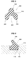
gasket 300 having a shape illustrated inFig. 6 has been proposed (Patent Document 2). - Namely, the
gasket 300 is constituted with abody section 310 inserted in amounting groove 100 of a case (one member) 100, and alip ridge protrusion 340 provided on another side of thebody section 310. Thelip ridge protrusion 340 has a shape extending in a tilted manner toward thebody section 310. - Therefore, as illustrated in
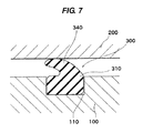
Fig. 7 , it can be expected to realize low reaction force of thelip ridge protrusion 340 and improve its followability at the time of gripping thelip ridge protrusion 340 between onemember 100 and theother member 200 so as to be in pressure contact with the two members. - However, as for such the
lip ridge protrusion 340 having a structure in a tilted manner, when thegasket 300 is formed and released, thelip ridge protrusion 340 is removed forcibly. Therefore, if thelip ridge protrusion 340 has a steeply tilted shape, there are problems that thelip ridge protrusion 340 is damaged easily so that the operability is low, or the like. - On the other hand, if the tilted angle of the
lip ridge protrusion 340 is small, low reaction force is hardly made even if thelip ridge protrusion 340 falls, and the change of reaction force to the compression amount increases. In addition, the lip ridge protrusion 340to hardly falls in the fixed direction as planned, and there is a possibility that thelip ridge protrusion 340 may partially fall in the opposite direction. As a result, lowering the sealing ability is caused. -
- Patent Document 1: Japanese Utility Model Laid-Open No.
62-108661 - Patent Document 2: Japanese Patent Application Laid-Open No.
2004-39341 - The purpose of the present invention is to provide a gasket which can be easily formed, can be compressed largely at low reaction force, and is highly reliable.
- According to an aspect of the present invention, a gasket made of a rubber-like elastic material is mounted in a mounting groove provided in one of two opposing members and is gripped between the one member and the other member so as to be in pressure contact with the two members. The gasket is provided with: a body section which is inserted in the mounting groove; one support protrusion, which is provided on one end side of the body section in the width direction so as to be located on the bottom side of the mounting groove, and is mounted in a deep groove provided in a part of the bottom; the other support protrusion which extends in a tilted manner from the other end side, in the width direction, of the body section toward the bottom in the direction away from the one support protrusion; and a lip ridge protrusion, which is provided on the side of the body section which faces the other member, and is located so that the tip thereof does not overlap the one support protrusion of the body section. In a step when the gasket is inserted, the body section is displaced so as to tilt on the other support protrusion side using the one support protrusion as a fulcrum.
- The present invention has the effects described below.
- According to a gasket of the invention described in claim 1, the gasket can be easily formed, can be easily formed, can be compressed largely at low reaction force, and is highly reliable.
- Further, according to a gasket of the invention described in
claim 2, the gasket can be compressed largely at low reaction force, and attitude stability of the gasket after being inserted is proper. - Further, according to a gasket of the invention described in
claim 3, the gasket can be easily, certainly mounted in the mounting groove. - Further, according to a gasket of the invention described in claim 4, since the lip ridge protrusion constantly falls in the fixed direction as planned, reliability of the sealing ability can increase.
- Further, according to a gasket of the invention described in claim 5, the gasket can be easily inserted in the mounting groove, and it can be prevented more certainly that the gasket falls on the inner peripheral side of the mounting groove.
- Furthermore, according to a gasket of the invention described in claim 6, the gasket can be compressed largely by further lower reaction force and is further highly reliable.
-
- [
Fig. 1 ] A cross-sectional view of a gasket according a first embodiment of the present invention - [
Fig. 2 ] A cross-sectional view of a state that the gasket inFig. 1 is inserted in a mounting groove - [
Fig. 3 ] A cross-sectional view of a state that the other member is assembled toFig. 2 and the gasket is gripped in pressure contact - [
Fig. 4 ] A view illustrating a second embodiment of the present invention, which is similar toFig. 1 - [
Fig. 5 ] A cross-sectional view of a gasket according to a conventional technique - [
Fig. 6 ] A cross-sectional view of the other gasket according to a conventional technique - [
Fig. 7 ] A cross-sectional view illustrating a state that the other member is assembled toFig. 6 and the gasket is gripped in pressure contact - Preferred embodiments for carrying out of the present invention will be described below.
- A gasket as a first embodiment according to the present invention is a
gasket 3 made of a rubber-like elastic material. As illustrated inFigs. 1, 2 and3 , thegasket 3 is mounted in amounting groove 11 provided in one of twoopposing members 1 and 2 and is gripped between the one member 1 and theother member 2 so as to be in pressure contact with the twomembers 1 and 2. - Further, the
gasket 3 is provided with: abody section 31 which is inserted in themounting groove 11; onesupport protrusion 33, which is provided on oneend side 312 of thebody section 31 in the width direction so as to be located on thebottom 111 side of themounting groove 11, and is mounted in adeep groove 112 provided in a part of thebottom 111; theother support protrusion 32 which extends in a tilted manner from theother end side 313, in the width direction, of thebody section 31 toward thebottom 111 in the direction away from the onesupport protrusion 33; alip ridge protrusion 34 being provided on the side of thebody section 31 facing theother member 2, and being located so that thetip 343 thereof does not overlap the onesupport protrusion 33 of thebody section 31. - The tilted angle of the
other support protrusion 32 with respect to thebottom 111 is within a range from 15 to 45 degrees. If the tilted angle is smaller than 15 decrees, a proper sealing surface pressure cannot be obtained. If the tilted angle is larger than 45 degrees, theother support protrusion 32 is removed forcibly at the time of forming and releasing. Therefore, if theother support protrusion 32 has a steeply tilted shape, there are problems that theother support protrusion 32 is damaged easily so that the operability is low, or the like. - Further, the
lip ridge portion 34 is formed so as to be upright to thebottom 111. - Further, in a state of assembling the
gasket 3, as illustrated inFig. 3 , thebody section 31 is thebody section 31 is displaced so as to tilt on theother support protrusion 32 side using the onesupport protrusion 33 as a fulcrum. - As mentioned above, the
other support protrusion 32 has a shape extending from theother end side 313, in the width direction, of thebody section 31 toward thebottom 111 in the direction away from the onesupport protrusion 33. As a result, when thelip ridge protrusion 34 is pressed by theother member 2, thelip ridge protrusion 34 is easily deformed as illustrated inFig. 3 . Therefore, the gasket can be easily formed, can be compressed largely at low reaction force, and is highly reliable. - Further, as illustrated in
Fig. 3 , the onesupport protrusion 33 stably holds thegasket 3 on the side of the one member 1, and theother support protrusion 32 contacts with thebottom 111 of themounting groove 11 at a wide area. Therefore, proper sealing ability can be exerted. - Further, in the constitution of the present invention, an aperture X exists between the
other support protrusion 32 and thebottom 111 in a stage before assembling thegasket 3, and theother support protrusion 32 contacts with thebottom 111 in a stage of assembling thegasket 3, as illustrated inFig. 2 . Therefore, the gasket can be compressed largely at low reaction force, and the attitude stability of the gasket after being assembled is proper. - Furthermore, the
body section 31 includes aflat press surface 311 on the side facing theother member 2 in which the onesupport protrusion 33 is provided. Therefore, when thegasket 3 is mounted in themounting groove 11, thepress surface 311 is pressed by a jig, so that thegasket 3 can be mounted easily. In addition, thegasket 3 can be mounted certainly. - Further, as illustrated in
Fig. 1 , as for the angles of both of tiltedsurfaces lip ridge protrusion 34 of thegasket 3, the tiltedsurface 341 on the side of theother support protrusion 32 is steeper than the other tiltedsurface 342. - Therefore, the
lip ridge protrusion 34 constantly falls in the fixed direction (on the left side inFig. 1 ) as planned, so that the reliability of sealing ability can be more improved. - Further, as illustrated in
Fig. 3 , thegasket 3 is designed to have a length so that the tip of theother support protrusion 32 does not contact with aside surface 113 of the mountinggroove 11, in the stage of assembling thegasket 3. As a result, displacing theother support protrusion 32 is not prevented by theside surface 113 of the mountinggroove 11, so thatgasket 3 can be compressed largely at low reaction force and is highly reliable. - A material used for a gasket 1 is a rubber-like elastic material.
- As the rubber material, nitrile rubber, acrylic rubber, EPDM, CR, silicone rubber, fluoro-rubber, natural rubber or the like can be used, and the rubber material can be selected properly from the rubbers according to a use.
- The strength of a rubber is preferably Hs 40 to Hs 60. It is important that the strength is smaller than Hs 70 so as to have low reaction force.
- Then, the second embodiment of the present invention will be described below with reference to
Fig. 4 . - The point which is different from the first embodiment is the point that a holding
protrusion 331 is provided on the peripheral surface of the onesupport protrusion 33. - The plural holding
protrusions 331 are provided at equal intervals on the inner peripheral side (the left side inFig. 4 ) of the onesupport protrusion 33. - Further, when the
gasket 3 is inserted in thedeep groove 112 of the mountinggroove 11, the holdingprotrusion 331 contacts with the peripheral surface of thedeep groove 112, so that thegasket 3 is assembled in a state of being gripped in pressure contact with the two members. - Therefore, according to the second embodiment of the present invention, insertion resistance of the
gasket 3 to the mountinggroove 11 can decrease. As a result, thegasket 3 can be easily inserted in thedeep groove 112, and it can be prevented more certainly that thegasket 3 falls on the inner peripheral side of the mountinggroove 11. - The gasket according to the present invention can be used as a gasket for a case, which is made of a low rigidity material such as synthetic resins, aluminum or the like and is used for electronic apparatuses or the like.
-
- 1: One member
- 2: The other member
- 3: Gasket
- 11: Mounting groove
- 31: Body section
- 32: The other support protrusion
- 33: One support protrusion
- 34: Lip ridge protrusion
- 111: Bottom
- 112: Deep groove
- 113: Side surface
- 312: One end side
- 313: The other end side
- 331: Holding protrusion
- 341: Tilted surface
- 342: Tilted surface
Claims (6)
- A gasket (3) made of a rubber-like elastic material,
wherein the gasket (3) mounted in a mounting groove (11) provided in one of two opposing members (1) and (2) and is gripped between the one member (1) and the other member (2) so as to be in pressure contact with the two members (1) and (2),
wherein the gasket (3) comprising:a body section (31) being inserted in the mounting groove (11);one support protrusion (33) being provided on one end side (312) of the body section (31) in the width direction so as to be located on the bottom (111) side of the mounting groove (11), and being mounted in a deep groove (112) provided in a part of the bottom (111);the other support protrusion (32) extending in a tilted manner from the other end side (313), in the width direction, of the body section (31) toward the bottom (111) in the direction away from the one support protrusion (33); anda lip ridge protrusion (34) being provided on the side of the body section (31) facing the other member (2), and being located so that the tip (343) thereof does not overlap the one support protrusion (33) of the body section (31), andwherein in a stage of assembling the gasket (3), the body section (31) is displaced so as to tilt on the other support protrusion (32) side using the one support protrusion (33) as a fulcrum.. - The gasket according to claim 1,
wherein an aperture (X) exists between the other support protrusion (32) and the bottom (111) in a stage before assembling the gasket (3), and the other support protrusion (32) is in contact with the bottom (111) in a stage of assembling the gasket 3. - The gasket according to claim 1 or 2,
wherein the body section (31) comprises a flat press surface (311) on the side facing the other member (2) in which the one support protrusion (33) is provided. - The gasket according to any one of claims 1 to 3,
wherein as for the angles of both of tilted surfaces (341) and (342) to form the lip ridge protrusion (34) of the gasket (3), the tilted surface (341) on the side of the other support protrusion (32) is steeper than the other tilted surface (342). - The gasket according to any one of claims 1 to 4,
wherein a holding protrusion (331) is provided on the peripheral surface of the one support protrusion (3). - The gasket according to any one of claims 1 to 4,
wherein the other support protrusion (32) has a length so as not to be in contact with a side surface (113) of the mounting groove (11), in the stage of assembling the gasket (3).
Applications Claiming Priority (2)
| Application Number | Priority Date | Filing Date | Title |
|---|---|---|---|
| JP2012090857A JP5240594B1 (en) | 2012-04-12 | 2012-04-12 | gasket |
| PCT/JP2012/083597 WO2013153715A1 (en) | 2012-04-12 | 2012-12-26 | Gasket |
Publications (3)
| Publication Number | Publication Date |
|---|---|
| EP2837854A1 true EP2837854A1 (en) | 2015-02-18 |
| EP2837854A4 EP2837854A4 (en) | 2015-08-19 |
| EP2837854B1 EP2837854B1 (en) | 2019-02-20 |
Family
ID=49041765
Family Applications (1)
| Application Number | Title | Priority Date | Filing Date |
|---|---|---|---|
| EP12874358.0A Active EP2837854B1 (en) | 2012-04-12 | 2012-12-26 | Gasket assembly |
Country Status (6)
| Country | Link |
|---|---|
| US (1) | US9426912B2 (en) |
| EP (1) | EP2837854B1 (en) |
| JP (1) | JP5240594B1 (en) |
| KR (1) | KR101947589B1 (en) |
| CN (1) | CN104185753B (en) |
| WO (1) | WO2013153715A1 (en) |
Families Citing this family (8)
| Publication number | Priority date | Publication date | Assignee | Title |
|---|---|---|---|---|
| KR102413324B1 (en) * | 2015-07-07 | 2022-06-27 | 엘지전자 주식회사 | Laundry treat machine |
| US10985043B2 (en) * | 2015-11-26 | 2021-04-20 | Miraial Co., Ltd. | Substrate housing container |
| JP6744810B2 (en) * | 2016-12-01 | 2020-08-19 | 川崎重工業株式会社 | Sealing structure of mold for manufacturing composite material structure |
| WO2018221412A1 (en) * | 2017-06-01 | 2018-12-06 | 信越ポリマー株式会社 | Substrate-accommodating container |
| US10473218B2 (en) * | 2017-10-09 | 2019-11-12 | Aptiv Technologies Limited | Perimeter seal |
| CN111480023B (en) * | 2017-12-20 | 2023-04-14 | 利乐拉瓦尔集团及财务有限公司 | Seal and tubular heat exchanger using the same |
| US12354897B2 (en) * | 2022-05-10 | 2025-07-08 | Entegris, Inc. | Substrate container with door gasket |
| US20240167568A1 (en) * | 2022-11-22 | 2024-05-23 | Parker-Hannifin Corporation | Friction fit seal with flange and flange sealing bead |
Family Cites Families (30)
| Publication number | Priority date | Publication date | Assignee | Title |
|---|---|---|---|---|
| US3554567A (en) * | 1966-03-16 | 1971-01-12 | Carrier Corp | Fluid seal |
| FR2535813B1 (en) * | 1982-11-05 | 1986-09-26 | Forsheda Sa | SEALING |
| FR2551522B1 (en) * | 1983-08-31 | 1985-10-25 | Pont A Mousson | GASKET FOR CAST IRON PIPES AND CENTERING MEANS PART OF THIS GASKET |
| JPS60192167A (en) | 1984-03-12 | 1985-09-30 | Nichirin Gomme Kogyo Kk | Packing of structure for water |
| JPS62108661U (en) | 1985-12-27 | 1987-07-11 | ||
| JPS6392712U (en) * | 1986-12-05 | 1988-06-15 | ||
| GB2217794B (en) * | 1988-04-29 | 1992-09-02 | Prior Clave Ltd | A pressure seal |
| JPH04258573A (en) * | 1991-02-07 | 1992-09-14 | Fuji Electric Co Ltd | Seal structure |
| US5112065A (en) * | 1991-03-14 | 1992-05-12 | Westinghouse Electric Corp. | Double directional gasket |
| US6354601B1 (en) * | 1999-01-06 | 2002-03-12 | Fluoroware, Inc. | Seal for wafer containers |
| JP3349132B2 (en) | 1999-04-12 | 2002-11-20 | 三菱電線工業株式会社 | Low load seal |
| US6364152B1 (en) * | 2000-04-12 | 2002-04-02 | Dart Industries Inc. | Food storage container |
| JP3556185B2 (en) | 2000-06-13 | 2004-08-18 | 信越ポリマー株式会社 | Seal member, sealed container and sealing method thereof |
| US7413099B2 (en) * | 2001-06-08 | 2008-08-19 | Shin-Etsu Polymer Co., Ltd. | Sealing element with a protruding part approximately obliquely outward and a hermetic container using the same |
| WO2003042059A1 (en) * | 2001-11-14 | 2003-05-22 | Entegris, Inc. | Wafer enclosure sealing arrangement for wafer containers |
| JP2003172454A (en) * | 2001-12-10 | 2003-06-20 | Nok Corp | Gasket |
| DE20203372U1 (en) | 2002-03-04 | 2002-06-20 | Imo Ind Momentenlager Stoll & | Rotary bearing for systems exposed to moisture |
| JP4099648B2 (en) | 2002-07-01 | 2008-06-11 | Nok株式会社 | Gasket for fuel cell |
| JP2004204941A (en) * | 2002-12-25 | 2004-07-22 | Keeper Co Ltd | Gasket |
| US7578407B2 (en) * | 2004-04-18 | 2009-08-25 | Entegris, Inc. | Wafer container with sealable door |
| JP4634772B2 (en) * | 2004-10-14 | 2011-02-16 | ミライアル株式会社 | Storage container |
| JP4482655B2 (en) * | 2005-04-22 | 2010-06-16 | ゴールド工業株式会社 | Gasket for precision substrate storage container |
| JP2007062804A (en) | 2005-08-31 | 2007-03-15 | Miraial Kk | Seal member |
| JP4875912B2 (en) * | 2006-03-24 | 2012-02-15 | Nok株式会社 | gasket |
| EP2022730B1 (en) * | 2006-05-29 | 2013-08-14 | Shin-Etsu Polymer Co. Ltd. | Substrate container |
| JPWO2009107495A1 (en) | 2008-02-29 | 2011-06-30 | 日本バルカー工業株式会社 | Sealing material and gate valve equipped with sealing material |
| JP5126999B2 (en) * | 2008-03-13 | 2013-01-23 | 日本バルカー工業株式会社 | Sealing material |
| DE112010005185B4 (en) * | 2010-01-26 | 2019-01-17 | Miraial Co., Ltd. | Semiconductor wafer storage container |
| JP5551947B2 (en) * | 2010-03-10 | 2014-07-16 | 東京エレクトロン株式会社 | Sealing material for grooves |
| JP5126423B2 (en) * | 2010-10-26 | 2013-01-23 | Nok株式会社 | gasket |
-
2012
- 2012-04-12 JP JP2012090857A patent/JP5240594B1/en active Active
- 2012-12-26 US US14/354,797 patent/US9426912B2/en active Active
- 2012-12-26 KR KR1020147013520A patent/KR101947589B1/en active Active
- 2012-12-26 EP EP12874358.0A patent/EP2837854B1/en active Active
- 2012-12-26 WO PCT/JP2012/083597 patent/WO2013153715A1/en not_active Ceased
- 2012-12-26 CN CN201280070161.7A patent/CN104185753B/en active Active
Also Published As
| Publication number | Publication date |
|---|---|
| CN104185753A (en) | 2014-12-03 |
| US9426912B2 (en) | 2016-08-23 |
| CN104185753B (en) | 2016-09-07 |
| KR101947589B1 (en) | 2019-02-14 |
| JP2013217481A (en) | 2013-10-24 |
| WO2013153715A1 (en) | 2013-10-17 |
| US20140291940A1 (en) | 2014-10-02 |
| KR20140143736A (en) | 2014-12-17 |
| EP2837854B1 (en) | 2019-02-20 |
| JP5240594B1 (en) | 2013-07-17 |
| EP2837854A4 (en) | 2015-08-19 |
Similar Documents
| Publication | Publication Date | Title |
|---|---|---|
| EP2837854B1 (en) | Gasket assembly | |
| JP5126423B2 (en) | gasket | |
| JP6165508B2 (en) | clip | |
| JP5760411B2 (en) | gasket | |
| EP2341268B1 (en) | Gasket | |
| US9587744B2 (en) | Sealing material | |
| KR101446990B1 (en) | Lateral sealing gasket and method | |
| KR102001873B1 (en) | Metal seal | |
| US20100140881A1 (en) | Sealing structure | |
| JP6917298B2 (en) | clip | |
| JP2003287139A (en) | Gasket | |
| RU2536344C2 (en) | Antenna mounting unit | |
| US6827353B2 (en) | Externally supported wide tolerance seal | |
| US9879779B2 (en) | Self-retaining gasket | |
| KR20130105475A (en) | Rubber ring for gasket | |
| US20150059131A1 (en) | Fixing Structure for Rope | |
| EP1640643A1 (en) | Gasket | |
| JP2016041969A (en) | Insulator | |
| JP2014040847A (en) | Waterproof packing | |
| JP6180713B2 (en) | Waterproof structure of the opening / closing part of the equipment case | |
| JP2002340190A (en) | Gasket | |
| JP7520358B2 (en) | Sealer | |
| JP2009257459A (en) | Gasket | |
| JP3198951U (en) | Blade type fixture | |
| JP2015087151A (en) | Oil level gauge |
Legal Events
| Date | Code | Title | Description |
|---|---|---|---|
| PUAI | Public reference made under article 153(3) epc to a published international application that has entered the european phase |
Free format text: ORIGINAL CODE: 0009012 |
|
| 17P | Request for examination filed |
Effective date: 20140513 |
|
| AK | Designated contracting states |
Kind code of ref document: A1 Designated state(s): AL AT BE BG CH CY CZ DE DK EE ES FI FR GB GR HR HU IE IS IT LI LT LU LV MC MK MT NL NO PL PT RO RS SE SI SK SM TR |
|
| AX | Request for extension of the european patent |
Extension state: BA ME |
|
| DAX | Request for extension of the european patent (deleted) | ||
| RA4 | Supplementary search report drawn up and despatched (corrected) |
Effective date: 20150717 |
|
| RIC1 | Information provided on ipc code assigned before grant |
Ipc: H05K 5/06 20060101ALI20150713BHEP Ipc: F16J 15/02 20060101ALI20150713BHEP Ipc: F16J 15/10 20060101AFI20150713BHEP |
|
| STAA | Information on the status of an ep patent application or granted ep patent |
Free format text: STATUS: EXAMINATION IS IN PROGRESS |
|
| 17Q | First examination report despatched |
Effective date: 20161103 |
|
| REG | Reference to a national code |
Ref country code: DE Ref legal event code: R079 Ref document number: 602012056977 Country of ref document: DE Free format text: PREVIOUS MAIN CLASS: F16J0015100000 Ipc: B65D0053020000 |
|
| GRAP | Despatch of communication of intention to grant a patent |
Free format text: ORIGINAL CODE: EPIDOSNIGR1 |
|
| STAA | Information on the status of an ep patent application or granted ep patent |
Free format text: STATUS: GRANT OF PATENT IS INTENDED |
|
| RIC1 | Information provided on ipc code assigned before grant |
Ipc: B65D 53/02 20060101AFI20180626BHEP Ipc: F16J 15/06 20060101ALI20180626BHEP Ipc: H05K 5/06 20060101ALI20180626BHEP Ipc: F16J 15/02 20060101ALI20180626BHEP Ipc: F16J 15/10 20060101ALI20180626BHEP |
|
| INTG | Intention to grant announced |
Effective date: 20180712 |
|
| GRAS | Grant fee paid |
Free format text: ORIGINAL CODE: EPIDOSNIGR3 |
|
| GRAA | (expected) grant |
Free format text: ORIGINAL CODE: 0009210 |
|
| STAA | Information on the status of an ep patent application or granted ep patent |
Free format text: STATUS: THE PATENT HAS BEEN GRANTED |
|
| AK | Designated contracting states |
Kind code of ref document: B1 Designated state(s): AL AT BE BG CH CY CZ DE DK EE ES FI FR GB GR HR HU IE IS IT LI LT LU LV MC MK MT NL NO PL PT RO RS SE SI SK SM TR |
|
| REG | Reference to a national code |
Ref country code: GB Ref legal event code: FG4D |
|
| REG | Reference to a national code |
Ref country code: CH Ref legal event code: EP |
|
| REG | Reference to a national code |
Ref country code: DE Ref legal event code: R096 Ref document number: 602012056977 Country of ref document: DE |
|
| REG | Reference to a national code |
Ref country code: AT Ref legal event code: REF Ref document number: 1097865 Country of ref document: AT Kind code of ref document: T Effective date: 20190315 |
|
| REG | Reference to a national code |
Ref country code: IE Ref legal event code: FG4D |
|
| REG | Reference to a national code |
Ref country code: NL Ref legal event code: MP Effective date: 20190220 |
|
| REG | Reference to a national code |
Ref country code: LT Ref legal event code: MG4D |
|
| PG25 | Lapsed in a contracting state [announced via postgrant information from national office to epo] |
Ref country code: PT Free format text: LAPSE BECAUSE OF FAILURE TO SUBMIT A TRANSLATION OF THE DESCRIPTION OR TO PAY THE FEE WITHIN THE PRESCRIBED TIME-LIMIT Effective date: 20190620 Ref country code: LT Free format text: LAPSE BECAUSE OF FAILURE TO SUBMIT A TRANSLATION OF THE DESCRIPTION OR TO PAY THE FEE WITHIN THE PRESCRIBED TIME-LIMIT Effective date: 20190220 Ref country code: NL Free format text: LAPSE BECAUSE OF FAILURE TO SUBMIT A TRANSLATION OF THE DESCRIPTION OR TO PAY THE FEE WITHIN THE PRESCRIBED TIME-LIMIT Effective date: 20190220 Ref country code: FI Free format text: LAPSE BECAUSE OF FAILURE TO SUBMIT A TRANSLATION OF THE DESCRIPTION OR TO PAY THE FEE WITHIN THE PRESCRIBED TIME-LIMIT Effective date: 20190220 Ref country code: NO Free format text: LAPSE BECAUSE OF FAILURE TO SUBMIT A TRANSLATION OF THE DESCRIPTION OR TO PAY THE FEE WITHIN THE PRESCRIBED TIME-LIMIT Effective date: 20190520 Ref country code: SE Free format text: LAPSE BECAUSE OF FAILURE TO SUBMIT A TRANSLATION OF THE DESCRIPTION OR TO PAY THE FEE WITHIN THE PRESCRIBED TIME-LIMIT Effective date: 20190220 |
|
| PG25 | Lapsed in a contracting state [announced via postgrant information from national office to epo] |
Ref country code: BG Free format text: LAPSE BECAUSE OF FAILURE TO SUBMIT A TRANSLATION OF THE DESCRIPTION OR TO PAY THE FEE WITHIN THE PRESCRIBED TIME-LIMIT Effective date: 20190520 Ref country code: IS Free format text: LAPSE BECAUSE OF FAILURE TO SUBMIT A TRANSLATION OF THE DESCRIPTION OR TO PAY THE FEE WITHIN THE PRESCRIBED TIME-LIMIT Effective date: 20190620 Ref country code: GR Free format text: LAPSE BECAUSE OF FAILURE TO SUBMIT A TRANSLATION OF THE DESCRIPTION OR TO PAY THE FEE WITHIN THE PRESCRIBED TIME-LIMIT Effective date: 20190521 Ref country code: RS Free format text: LAPSE BECAUSE OF FAILURE TO SUBMIT A TRANSLATION OF THE DESCRIPTION OR TO PAY THE FEE WITHIN THE PRESCRIBED TIME-LIMIT Effective date: 20190220 Ref country code: LV Free format text: LAPSE BECAUSE OF FAILURE TO SUBMIT A TRANSLATION OF THE DESCRIPTION OR TO PAY THE FEE WITHIN THE PRESCRIBED TIME-LIMIT Effective date: 20190220 Ref country code: HR Free format text: LAPSE BECAUSE OF FAILURE TO SUBMIT A TRANSLATION OF THE DESCRIPTION OR TO PAY THE FEE WITHIN THE PRESCRIBED TIME-LIMIT Effective date: 20190220 |
|
| REG | Reference to a national code |
Ref country code: AT Ref legal event code: MK05 Ref document number: 1097865 Country of ref document: AT Kind code of ref document: T Effective date: 20190220 |
|
| PG25 | Lapsed in a contracting state [announced via postgrant information from national office to epo] |
Ref country code: RO Free format text: LAPSE BECAUSE OF FAILURE TO SUBMIT A TRANSLATION OF THE DESCRIPTION OR TO PAY THE FEE WITHIN THE PRESCRIBED TIME-LIMIT Effective date: 20190220 Ref country code: IT Free format text: LAPSE BECAUSE OF FAILURE TO SUBMIT A TRANSLATION OF THE DESCRIPTION OR TO PAY THE FEE WITHIN THE PRESCRIBED TIME-LIMIT Effective date: 20190220 Ref country code: SK Free format text: LAPSE BECAUSE OF FAILURE TO SUBMIT A TRANSLATION OF THE DESCRIPTION OR TO PAY THE FEE WITHIN THE PRESCRIBED TIME-LIMIT Effective date: 20190220 Ref country code: CZ Free format text: LAPSE BECAUSE OF FAILURE TO SUBMIT A TRANSLATION OF THE DESCRIPTION OR TO PAY THE FEE WITHIN THE PRESCRIBED TIME-LIMIT Effective date: 20190220 Ref country code: AL Free format text: LAPSE BECAUSE OF FAILURE TO SUBMIT A TRANSLATION OF THE DESCRIPTION OR TO PAY THE FEE WITHIN THE PRESCRIBED TIME-LIMIT Effective date: 20190220 Ref country code: DK Free format text: LAPSE BECAUSE OF FAILURE TO SUBMIT A TRANSLATION OF THE DESCRIPTION OR TO PAY THE FEE WITHIN THE PRESCRIBED TIME-LIMIT Effective date: 20190220 Ref country code: ES Free format text: LAPSE BECAUSE OF FAILURE TO SUBMIT A TRANSLATION OF THE DESCRIPTION OR TO PAY THE FEE WITHIN THE PRESCRIBED TIME-LIMIT Effective date: 20190220 Ref country code: EE Free format text: LAPSE BECAUSE OF FAILURE TO SUBMIT A TRANSLATION OF THE DESCRIPTION OR TO PAY THE FEE WITHIN THE PRESCRIBED TIME-LIMIT Effective date: 20190220 |
|
| REG | Reference to a national code |
Ref country code: DE Ref legal event code: R097 Ref document number: 602012056977 Country of ref document: DE |
|
| PG25 | Lapsed in a contracting state [announced via postgrant information from national office to epo] |
Ref country code: SM Free format text: LAPSE BECAUSE OF FAILURE TO SUBMIT A TRANSLATION OF THE DESCRIPTION OR TO PAY THE FEE WITHIN THE PRESCRIBED TIME-LIMIT Effective date: 20190220 Ref country code: PL Free format text: LAPSE BECAUSE OF FAILURE TO SUBMIT A TRANSLATION OF THE DESCRIPTION OR TO PAY THE FEE WITHIN THE PRESCRIBED TIME-LIMIT Effective date: 20190220 |
|
| PLBE | No opposition filed within time limit |
Free format text: ORIGINAL CODE: 0009261 |
|
| STAA | Information on the status of an ep patent application or granted ep patent |
Free format text: STATUS: NO OPPOSITION FILED WITHIN TIME LIMIT |
|
| PG25 | Lapsed in a contracting state [announced via postgrant information from national office to epo] |
Ref country code: AT Free format text: LAPSE BECAUSE OF FAILURE TO SUBMIT A TRANSLATION OF THE DESCRIPTION OR TO PAY THE FEE WITHIN THE PRESCRIBED TIME-LIMIT Effective date: 20190220 |
|
| 26N | No opposition filed |
Effective date: 20191121 |
|
| PG25 | Lapsed in a contracting state [announced via postgrant information from national office to epo] |
Ref country code: SI Free format text: LAPSE BECAUSE OF FAILURE TO SUBMIT A TRANSLATION OF THE DESCRIPTION OR TO PAY THE FEE WITHIN THE PRESCRIBED TIME-LIMIT Effective date: 20190220 |
|
| PG25 | Lapsed in a contracting state [announced via postgrant information from national office to epo] |
Ref country code: TR Free format text: LAPSE BECAUSE OF FAILURE TO SUBMIT A TRANSLATION OF THE DESCRIPTION OR TO PAY THE FEE WITHIN THE PRESCRIBED TIME-LIMIT Effective date: 20190220 |
|
| REG | Reference to a national code |
Ref country code: CH Ref legal event code: PL |
|
| REG | Reference to a national code |
Ref country code: BE Ref legal event code: MM Effective date: 20191231 |
|
| PG25 | Lapsed in a contracting state [announced via postgrant information from national office to epo] |
Ref country code: MC Free format text: LAPSE BECAUSE OF FAILURE TO SUBMIT A TRANSLATION OF THE DESCRIPTION OR TO PAY THE FEE WITHIN THE PRESCRIBED TIME-LIMIT Effective date: 20190220 |
|
| PG25 | Lapsed in a contracting state [announced via postgrant information from national office to epo] |
Ref country code: IE Free format text: LAPSE BECAUSE OF NON-PAYMENT OF DUE FEES Effective date: 20191226 Ref country code: LU Free format text: LAPSE BECAUSE OF NON-PAYMENT OF DUE FEES Effective date: 20191226 |
|
| PG25 | Lapsed in a contracting state [announced via postgrant information from national office to epo] |
Ref country code: CH Free format text: LAPSE BECAUSE OF NON-PAYMENT OF DUE FEES Effective date: 20191231 Ref country code: LI Free format text: LAPSE BECAUSE OF NON-PAYMENT OF DUE FEES Effective date: 20191231 Ref country code: BE Free format text: LAPSE BECAUSE OF NON-PAYMENT OF DUE FEES Effective date: 20191231 |
|
| PG25 | Lapsed in a contracting state [announced via postgrant information from national office to epo] |
Ref country code: CY Free format text: LAPSE BECAUSE OF FAILURE TO SUBMIT A TRANSLATION OF THE DESCRIPTION OR TO PAY THE FEE WITHIN THE PRESCRIBED TIME-LIMIT Effective date: 20190220 |
|
| PG25 | Lapsed in a contracting state [announced via postgrant information from national office to epo] |
Ref country code: MT Free format text: LAPSE BECAUSE OF FAILURE TO SUBMIT A TRANSLATION OF THE DESCRIPTION OR TO PAY THE FEE WITHIN THE PRESCRIBED TIME-LIMIT Effective date: 20190220 Ref country code: HU Free format text: LAPSE BECAUSE OF FAILURE TO SUBMIT A TRANSLATION OF THE DESCRIPTION OR TO PAY THE FEE WITHIN THE PRESCRIBED TIME-LIMIT; INVALID AB INITIO Effective date: 20121226 |
|
| PG25 | Lapsed in a contracting state [announced via postgrant information from national office to epo] |
Ref country code: MK Free format text: LAPSE BECAUSE OF FAILURE TO SUBMIT A TRANSLATION OF THE DESCRIPTION OR TO PAY THE FEE WITHIN THE PRESCRIBED TIME-LIMIT Effective date: 20190220 |
|
| PGFP | Annual fee paid to national office [announced via postgrant information from national office to epo] |
Ref country code: DE Payment date: 20251028 Year of fee payment: 14 |
|
| PGFP | Annual fee paid to national office [announced via postgrant information from national office to epo] |
Ref country code: GB Payment date: 20251114 Year of fee payment: 14 |
|
| PGFP | Annual fee paid to national office [announced via postgrant information from national office to epo] |
Ref country code: FR Payment date: 20251110 Year of fee payment: 14 |