EP2837818A1 - Windturbine mit Gierlagerhubvorrichtung - Google Patents
Windturbine mit Gierlagerhubvorrichtung Download PDFInfo
- Publication number
- EP2837818A1 EP2837818A1 EP13180231.6A EP13180231A EP2837818A1 EP 2837818 A1 EP2837818 A1 EP 2837818A1 EP 13180231 A EP13180231 A EP 13180231A EP 2837818 A1 EP2837818 A1 EP 2837818A1
- Authority
- EP
- European Patent Office
- Prior art keywords
- wind turbine
- nacelle
- yaw bearing
- yaw
- tower
- Prior art date
- Legal status (The legal status is an assumption and is not a legal conclusion. Google has not performed a legal analysis and makes no representation as to the accuracy of the status listed.)
- Granted
Links
- 238000000034 method Methods 0.000 claims abstract description 8
- 210000002445 nipple Anatomy 0.000 claims description 3
- 239000012530 fluid Substances 0.000 description 7
- 238000005096 rolling process Methods 0.000 description 3
- 239000007788 liquid Substances 0.000 description 2
- 239000000463 material Substances 0.000 description 2
- XLYOFNOQVPJJNP-UHFFFAOYSA-N water Substances O XLYOFNOQVPJJNP-UHFFFAOYSA-N 0.000 description 2
- 238000005303 weighing Methods 0.000 description 2
- 239000004677 Nylon Substances 0.000 description 1
- 230000009286 beneficial effect Effects 0.000 description 1
- 230000001419 dependent effect Effects 0.000 description 1
- 238000011161 development Methods 0.000 description 1
- 230000018109 developmental process Effects 0.000 description 1
- 230000002706 hydrostatic effect Effects 0.000 description 1
- 238000012986 modification Methods 0.000 description 1
- 230000004048 modification Effects 0.000 description 1
- 229920001778 nylon Polymers 0.000 description 1
- 230000000284 resting effect Effects 0.000 description 1
Images


Classifications
-
- E—FIXED CONSTRUCTIONS
- E04—BUILDING
- E04H—BUILDINGS OR LIKE STRUCTURES FOR PARTICULAR PURPOSES; SWIMMING OR SPLASH BATHS OR POOLS; MASTS; FENCING; TENTS OR CANOPIES, IN GENERAL
- E04H12/00—Towers; Masts or poles; Chimney stacks; Water-towers; Methods of erecting such structures
-
- E—FIXED CONSTRUCTIONS
- E04—BUILDING
- E04H—BUILDINGS OR LIKE STRUCTURES FOR PARTICULAR PURPOSES; SWIMMING OR SPLASH BATHS OR POOLS; MASTS; FENCING; TENTS OR CANOPIES, IN GENERAL
- E04H12/00—Towers; Masts or poles; Chimney stacks; Water-towers; Methods of erecting such structures
- E04H12/34—Arrangements for erecting or lowering towers, masts, poles, chimney stacks, or the like
-
- F—MECHANICAL ENGINEERING; LIGHTING; HEATING; WEAPONS; BLASTING
- F03—MACHINES OR ENGINES FOR LIQUIDS; WIND, SPRING, OR WEIGHT MOTORS; PRODUCING MECHANICAL POWER OR A REACTIVE PROPULSIVE THRUST, NOT OTHERWISE PROVIDED FOR
- F03D—WIND MOTORS
- F03D13/00—Assembly, mounting or commissioning of wind motors; Arrangements specially adapted for transporting wind motor components
- F03D13/20—Arrangements for mounting or supporting wind motors; Masts or towers for wind motors
-
- F—MECHANICAL ENGINEERING; LIGHTING; HEATING; WEAPONS; BLASTING
- F03—MACHINES OR ENGINES FOR LIQUIDS; WIND, SPRING, OR WEIGHT MOTORS; PRODUCING MECHANICAL POWER OR A REACTIVE PROPULSIVE THRUST, NOT OTHERWISE PROVIDED FOR
- F03D—WIND MOTORS
- F03D80/00—Details, components or accessories not provided for in groups F03D1/00 - F03D17/00
- F03D80/50—Maintenance or repair
-
- F—MECHANICAL ENGINEERING; LIGHTING; HEATING; WEAPONS; BLASTING
- F03—MACHINES OR ENGINES FOR LIQUIDS; WIND, SPRING, OR WEIGHT MOTORS; PRODUCING MECHANICAL POWER OR A REACTIVE PROPULSIVE THRUST, NOT OTHERWISE PROVIDED FOR
- F03D—WIND MOTORS
- F03D80/00—Details, components or accessories not provided for in groups F03D1/00 - F03D17/00
- F03D80/70—Bearing or lubricating arrangements
-
- F—MECHANICAL ENGINEERING; LIGHTING; HEATING; WEAPONS; BLASTING
- F16—ENGINEERING ELEMENTS AND UNITS; GENERAL MEASURES FOR PRODUCING AND MAINTAINING EFFECTIVE FUNCTIONING OF MACHINES OR INSTALLATIONS; THERMAL INSULATION IN GENERAL
- F16C—SHAFTS; FLEXIBLE SHAFTS; ELEMENTS OR CRANKSHAFT MECHANISMS; ROTARY BODIES OTHER THAN GEARING ELEMENTS; BEARINGS
- F16C17/00—Sliding-contact bearings for exclusively rotary movement
- F16C17/04—Sliding-contact bearings for exclusively rotary movement for axial load only
-
- F—MECHANICAL ENGINEERING; LIGHTING; HEATING; WEAPONS; BLASTING
- F16—ENGINEERING ELEMENTS AND UNITS; GENERAL MEASURES FOR PRODUCING AND MAINTAINING EFFECTIVE FUNCTIONING OF MACHINES OR INSTALLATIONS; THERMAL INSULATION IN GENERAL
- F16C—SHAFTS; FLEXIBLE SHAFTS; ELEMENTS OR CRANKSHAFT MECHANISMS; ROTARY BODIES OTHER THAN GEARING ELEMENTS; BEARINGS
- F16C33/00—Parts of bearings; Special methods for making bearings or parts thereof
- F16C33/02—Parts of sliding-contact bearings
- F16C33/04—Brasses; Bushes; Linings
- F16C33/20—Sliding surface consisting mainly of plastics
-
- F—MECHANICAL ENGINEERING; LIGHTING; HEATING; WEAPONS; BLASTING
- F16—ENGINEERING ELEMENTS AND UNITS; GENERAL MEASURES FOR PRODUCING AND MAINTAINING EFFECTIVE FUNCTIONING OF MACHINES OR INSTALLATIONS; THERMAL INSULATION IN GENERAL
- F16C—SHAFTS; FLEXIBLE SHAFTS; ELEMENTS OR CRANKSHAFT MECHANISMS; ROTARY BODIES OTHER THAN GEARING ELEMENTS; BEARINGS
- F16C33/00—Parts of bearings; Special methods for making bearings or parts thereof
- F16C33/02—Parts of sliding-contact bearings
- F16C33/04—Brasses; Bushes; Linings
- F16C33/26—Brasses; Bushes; Linings made from wire coils; made from a number of discs, rings, rods, or other members
-
- F—MECHANICAL ENGINEERING; LIGHTING; HEATING; WEAPONS; BLASTING
- F05—INDEXING SCHEMES RELATING TO ENGINES OR PUMPS IN VARIOUS SUBCLASSES OF CLASSES F01-F04
- F05B—INDEXING SCHEME RELATING TO WIND, SPRING, WEIGHT, INERTIA OR LIKE MOTORS, TO MACHINES OR ENGINES FOR LIQUIDS COVERED BY SUBCLASSES F03B, F03D AND F03G
- F05B2230/00—Manufacture
- F05B2230/80—Repairing, retrofitting or upgrading methods
-
- F—MECHANICAL ENGINEERING; LIGHTING; HEATING; WEAPONS; BLASTING
- F05—INDEXING SCHEMES RELATING TO ENGINES OR PUMPS IN VARIOUS SUBCLASSES OF CLASSES F01-F04
- F05B—INDEXING SCHEME RELATING TO WIND, SPRING, WEIGHT, INERTIA OR LIKE MOTORS, TO MACHINES OR ENGINES FOR LIQUIDS COVERED BY SUBCLASSES F03B, F03D AND F03G
- F05B2240/00—Components
- F05B2240/50—Bearings
-
- F—MECHANICAL ENGINEERING; LIGHTING; HEATING; WEAPONS; BLASTING
- F05—INDEXING SCHEMES RELATING TO ENGINES OR PUMPS IN VARIOUS SUBCLASSES OF CLASSES F01-F04
- F05B—INDEXING SCHEME RELATING TO WIND, SPRING, WEIGHT, INERTIA OR LIKE MOTORS, TO MACHINES OR ENGINES FOR LIQUIDS COVERED BY SUBCLASSES F03B, F03D AND F03G
- F05B2240/00—Components
- F05B2240/90—Mounting on supporting structures or systems
- F05B2240/91—Mounting on supporting structures or systems on a stationary structure
- F05B2240/916—Mounting on supporting structures or systems on a stationary structure with provision for hoisting onto the structure
-
- F—MECHANICAL ENGINEERING; LIGHTING; HEATING; WEAPONS; BLASTING
- F16—ENGINEERING ELEMENTS AND UNITS; GENERAL MEASURES FOR PRODUCING AND MAINTAINING EFFECTIVE FUNCTIONING OF MACHINES OR INSTALLATIONS; THERMAL INSULATION IN GENERAL
- F16C—SHAFTS; FLEXIBLE SHAFTS; ELEMENTS OR CRANKSHAFT MECHANISMS; ROTARY BODIES OTHER THAN GEARING ELEMENTS; BEARINGS
- F16C2360/00—Engines or pumps
- F16C2360/31—Wind motors
-
- Y—GENERAL TAGGING OF NEW TECHNOLOGICAL DEVELOPMENTS; GENERAL TAGGING OF CROSS-SECTIONAL TECHNOLOGIES SPANNING OVER SEVERAL SECTIONS OF THE IPC; TECHNICAL SUBJECTS COVERED BY FORMER USPC CROSS-REFERENCE ART COLLECTIONS [XRACs] AND DIGESTS
- Y02—TECHNOLOGIES OR APPLICATIONS FOR MITIGATION OR ADAPTATION AGAINST CLIMATE CHANGE
- Y02E—REDUCTION OF GREENHOUSE GAS [GHG] EMISSIONS, RELATED TO ENERGY GENERATION, TRANSMISSION OR DISTRIBUTION
- Y02E10/00—Energy generation through renewable energy sources
- Y02E10/70—Wind energy
- Y02E10/72—Wind turbines with rotation axis in wind direction
-
- Y—GENERAL TAGGING OF NEW TECHNOLOGICAL DEVELOPMENTS; GENERAL TAGGING OF CROSS-SECTIONAL TECHNOLOGIES SPANNING OVER SEVERAL SECTIONS OF THE IPC; TECHNICAL SUBJECTS COVERED BY FORMER USPC CROSS-REFERENCE ART COLLECTIONS [XRACs] AND DIGESTS
- Y02—TECHNOLOGIES OR APPLICATIONS FOR MITIGATION OR ADAPTATION AGAINST CLIMATE CHANGE
- Y02E—REDUCTION OF GREENHOUSE GAS [GHG] EMISSIONS, RELATED TO ENERGY GENERATION, TRANSMISSION OR DISTRIBUTION
- Y02E10/00—Energy generation through renewable energy sources
- Y02E10/70—Wind energy
- Y02E10/728—Onshore wind turbines
-
- Y—GENERAL TAGGING OF NEW TECHNOLOGICAL DEVELOPMENTS; GENERAL TAGGING OF CROSS-SECTIONAL TECHNOLOGIES SPANNING OVER SEVERAL SECTIONS OF THE IPC; TECHNICAL SUBJECTS COVERED BY FORMER USPC CROSS-REFERENCE ART COLLECTIONS [XRACs] AND DIGESTS
- Y02—TECHNOLOGIES OR APPLICATIONS FOR MITIGATION OR ADAPTATION AGAINST CLIMATE CHANGE
- Y02P—CLIMATE CHANGE MITIGATION TECHNOLOGIES IN THE PRODUCTION OR PROCESSING OF GOODS
- Y02P70/00—Climate change mitigation technologies in the production process for final industrial or consumer products
- Y02P70/50—Manufacturing or production processes characterised by the final manufactured product
Definitions
- the present invention relates to a wind turbine with a lifting device. Furthermore, the invention relates to a method of lifting a nacelle of a wind turbine relative to a tower of the wind turbine.
- a wind turbine with a tower and a nacelle typically comprises a yaw bearing by which the nacelle can be rotated relative to the tower.
- the yaw bearing may comprise sliding components, for example bearing pads. These bearing pads may be needed to be exchanged from time to time. An exchange of a sliding component may be necessary e.g. because of wear.
- a wind turbine with a tower, a nacelle and a yaw bearing, wherein the yaw bearing is arranged and prepared for rotating the nacelle relative to the tower around a yaw axis.
- the yaw bearing comprises a first yaw bearing component which is fixed to the tower, a second yaw bearing component which is fixed to the nacelle, and at least one sliding component which is located between the first yaw bearing component and the second yaw bearing component.
- the wind turbine is prepared and arranged for housing at least one lifting device for lifting the nacelle relative to the tower such that the sliding component can be removed.
- a wind turbine which may also be referred to as a wind turbine engine, a wind power plant or a wind charger, converts kinetic energy from wind, also called wind energy, into mechanical energy.
- the wind turbine may also comprise a hub, a rotor, a generator, and one or several rotor blades.
- a yaw bearing may in general comprise a rolling element bearing with balls or rollers which aim reducing friction between a first bearing component and a second bearing component.
- Rolling elements that are used in rolling element bearings may be cylindrical rollers, tapered rollers, spherical rollers or needles.
- Another alternative for the yaw bearing is a fluid bearing.
- a fluid bearing supports the bearing's loads solely on a layer of liquid or gas, in particular a thin layer of liquid or gas with a layer thickness below 1 mm (millimetre).
- Hydrostatic bearings are externally pressurized fluid bearings, where a fluid, e.g. oil, water or air, is pressurized by a pump.
- Hydrodynamic bearings rely on a high speed of a journal, a journal being a part of a shaft resting on the fluid, to pressurize the fluid in a wedge between the contact faces of the bearing components.
- the yaw bearing is a fluid bearing or gliding bearing and the sliding component is a so called bearing pad.
- the lifting device lifts the nacelle relative to the tower in a certain lifting direction. Assuming that for example the tower stands in a vertical direction, then the lifting device may lift the nacelle horizontally, vertically, oblige or slanting, or in an arch-shaped or circular-shaped manner.
- the lifting device may be located internally or externally.
- internally refers to a position within the nacelle or within the tower or within the yaw bearing.
- the lifting device can not be spotted from outside the wind turbine.
- the lifting device is positioned outside of the wind turbine.
- the lifting device may be placed on a shelf which is running at least partially around the nacelle or the tower.
- the yaw axis and a lifting direction which is defined by a direction in which the nacelle is lifted relative to the tower, comprise a lifting angle which is between 0° and 20°, in particular between 0° and 10°.
- the lifting angle is 0°. If, however, the nacelle is lifted in a straight movement relative to the tower and a direction of this straight movement is not in parallel with the yaw axis, then the lifting angle is different from 0°. If, in another example, the nacelle is moved in an arc-shaped movement, which is for example the case when the nacelle is moved around a hinge, then the lifting angle is determined by the angle which is comprised by the yaw axis and the final position of the nacelle.
- the lifting device lifts the nacelle substantially vertically relative to the tower.
- the nacelle comprises a weight which exerts a gravitational force on the tower, and the gravitational force of the nacelle is exerted at least partially on the sliding component.
- a gliding bearing may comprise different types of bearing pads.
- These different types of bearing pads include top-axial bearing pads, radial bearing pads and bottom axial bearing pads.
- top-axial bearing pads Assuming again for example a vertical tower and a nacelle which is placed upon the tower, then the top-axial bearing pad is positioned right between the tower and the nacelle, type of sandwiched in-between the tower and the nacelle. In other words, the top-axial bearing pad extends in a horizontal plane.
- Bottom-axial bearing pads are substantially parallel to top-axial bearing pads. This means that a bottom-axial bearing pad may also extend substantially in a horizontal plane.
- top-axial bearing pad supports fully or partially the weight of the nacelle.
- bottom-axial bearing pad solely supports the load which is exerted from e.g. wind pushing the nacelle from the bottom to the top.
- a radial bearing pad may extend in a plane which is perpendicular to the horizontal plane of the top-axial bearing pad and the bottom-axial bearing pad.
- the sliding component refers to a top-axial bearing pad.
- top-axial bearing pad which is difficult and challenging for being removed or exchanged because of the heavy weight of the nacelle which has to be lifted in order to replace the bearing pad.
- the lifting device as described above may also be used to remove the other types of bearing pads.
- access to these types of bearing pads may already be relatively easy, depending of course on the type of yaw bearing and wind turbine in which they are a part.
- top-axial bearing pad is a top-axial gliding bearing or a top-sliding shoe.
- the other types of bearing pads may also be referred to as a radial gliding bearing and a bottom-axial gliding bearing, respectively.
- the first yaw bearing component and/or the second yaw bearing component comprises at least one pocket for housing the lifting device.
- the pocket may be machined in the first yaw bearing and/or the second yaw bearing.
- the pocket may for example be grinded into the yaw bearing component.
- the first yaw bearing component comprises a material which is easier to machine, i.e. to grind, then it is advantageously to place the pocket in the first yaw bearing component.
- the pocket may comprise a square shape or a round or curved shape or any other shape. It is advantageous if the shape of the pocket suits and corresponds to the lifting device for which it is arranged and prepared to housing it.
- first yaw bearing component and/or the second yaw bearing component comprises a yaw ring.
- a yaw ring may comprise a shape of a hollow cylinder. It may also comprise a shape of a disc.
- the first yaw bearing component comprises a shape of a yaw ring and the yaw ring is placed on an upper rim of the tower.
- the lifting device is a hydraulic lifting device.
- a hydraulic lifting device In principle, any physical principle can be applied to lift the nacelle relative to the tower.
- a hydraulic lifting device has the advantage that high pressures and lifting capabilities can be generated without relying to much space and power requirements.
- a hydraulic lifting device a hydraulic pressure has to be generated and thus the object is lifted.
- the hydraulic lifting device may be operated by oil and/or water.
- the first yaw bearing component and/or the second yaw bearing component comprises at least one further pocket for housing at least one further lifting device.
- a plurality of lifting devices are used to lift the nacelle relative to the power. For example 5 to 15 lifting devices are used at the same time. Beneficially, exactly one lifting device is placed in one pocket.
- a hydraulic pressure is exerted on the lifting device and a further hydraulic pressure is exerted on the further lifting device.
- the hydraulic pressure and the further hydraulic pressure are substantially equal.
- the lifting device and the further lifting device may be serial connected. This means that with one common pressure generation device both lifting devices are operated. Alternatively, the lifting devices may be operated separately; however, the same hydraulic pressure is applied to both of the lifting devices.
- the lifting device comprises a lifting cylinder and an extension nipple for building up the hydraulic pressure.
- a hydraulic torch tool is used for building up the hydraulic pressure.
- This may be the same hydraulic torch tool which may also be used for securing bolts or screws of the wind turbine.
- the hydraulic torch tool may be a mobile tool with a weight below 20 kg (kilogramme) such that a man is able to carry it.
- the lifting device may be able to lift a weight between 20 t (tons) and 200 t. Furthermore, the lifting device may be able to lift an object by a height of up to 20 mm, in particular up to 8 mm.
- the lifting cylinder comprises substantially a shape of a circular cylinder.
- the lifting cylinders may have extensions or dents or bumps.
- the lifting cylinder may for example comprise a diameter of between 5 cm (centimetre) and 25 cm.
- the lifting cylinder may have a height between 2 cm and 8 cm.
- the wind turbine is a direct drive wind turbine.
- the invention is also directed to a method of lifting a nacelle of a wind turbine relative to a tower of the wind turbine.
- the method comprises
- the method of lifting the nacelle relative to the tower may beneficially be used for exchanging the sliding component, e.g. the top-axial bearing pad, without a huge effort. This is particularly beneficial in offshore wind turbines.
- the sliding component e.g. the top-axial bearing pad
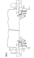
- a wind turbine 10 with a tower 11 and a nacelle 12 is joined with the tower 11 by a yaw bearing 20.
- the yaw bearing 20 enables a rotation of the nacelle 12 relative to the tower 11 about a yaw axis 21.
- the wind turbine 10 comprises a hub 13 which is joined or connected by three rotor blades 14 (two of the rotor blades 14 are shown in figure 1 ).
- the hub 13 is connected with a rotor and is rotatably mounted about a rotor axis of rotation 15.
- the yaw bearing 20 comprises a first yaw bearing component 22 which has a shape of a yaw ring 25, and which is directly joined to a tower 11.
- the yaw bearing 20 also comprises a second yaw bearing 23 which is directly joined to a nacelle 12.
- the second yaw bearing component 23 can be rotated relative to the first bearing component 22 by a set of inner yaw drives 24.
- the first yaw bearing component 22 and the second yaw bearing component 23 are in contact by bearing pads.
- top-axial bearing pad 41 a top-axial bearing pad 41, a radial bearing pad 42 and a bottom-axial bearing pad 43 are depicted.
- the top-axial bearing pad acting as a sliding component 40, bears a main load or weight of the nacelle 12.
- the radial bearing pad 42 and the bottom axial bearing pad 43 only bear additional loads exerted on the wind turbine 10.
- Figure 3 shows a similar setup of a yaw bearing 20.
- the yaw drive 24 is arranged outside with regard to walls of the tower 11.
- a lifting angle 35 comprised by a yaw axis 21 and a lifting direction 34 is illustrated.
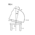
- a lifting device 31 acts similarly to a hinge and tilts the nacelle 12 relative to the tower 11 of the wind turbine 10.
- a first yaw bearing component 22 is joined with the tower 11 and a second yaw bearing component 23 is joined with the nacelle 12. More specifically, the second yaw bearing component 23 is directly joined with a support structure 33 of the wind turbine 10.
- the support structure 33 is a part of the nacelle 12.
- the support structure 33 comprises in the example shown in Figure 4 a shape of a swan neck.
- the lifting angle 35 comprises 12°.
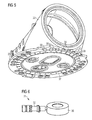
- the second yaw bearing component 23 shown in figure 5 is a part of a wind turbine 10 which is able to generate an electrical power of 6 MW.
- the second yaw bearing component 23 comprises a shape which is also called a bed frame or bed plate or base frame.
- the second yaw bearing component 23 is arranged and prepared to house sliding components in a sliding component pocket 37.
- 34 sliding component pockets 37 are shown.
- eight pockets 30 have been grinded into a second yaw bearing component 23.
- the pockets 30 have a shape of a square with one side rounded or curved.
- a sliding component may exemplarily have the following dimensions: 310 mm times 243 mm times 15 mm.
- a material of the sliding component may comprise nylon.
- an exemplary lifting device 31 comprising an extension nipple 32 and a lifting cylinder 36 is shown.
- the lifting cylinder 36 comprises a shape of a hollow circular cylinder. It comprises an outer diameter of 200 mm and an inner diameter of 100 mm. It furthermore comprises a height of 65 mm.
- the lifting device 31 as shown in Figure 6 comprises a stroke of 6 mm and comprises a capacity of lifting up to 100 t. A working pressure of 700 bar is needed to operate the lifting device 31 shown in Figure 5 .
Landscapes
- Engineering & Computer Science (AREA)
- General Engineering & Computer Science (AREA)
- Mechanical Engineering (AREA)
- Life Sciences & Earth Sciences (AREA)
- Sustainable Development (AREA)
- Sustainable Energy (AREA)
- Chemical & Material Sciences (AREA)
- Combustion & Propulsion (AREA)
- Architecture (AREA)
- Civil Engineering (AREA)
- Structural Engineering (AREA)
- Wind Motors (AREA)
Priority Applications (4)
| Application Number | Priority Date | Filing Date | Title |
|---|---|---|---|
| EP13180231.6A EP2837818B1 (de) | 2013-08-13 | 2013-08-13 | Windturbine mit Gierlagerhubvorrichtung |
| DK13180231.6T DK2837818T3 (en) | 2013-08-13 | 2013-08-13 | Wind turbine with bend bearing lift device |
| US14/318,603 US9689174B2 (en) | 2013-08-13 | 2014-06-28 | Wind turbine with yaw bearing lifting device |
| CN201410396121.2A CN104373288B (zh) | 2013-08-13 | 2014-08-13 | 具有偏转轴承抬升装置的风力涡轮机 |
Applications Claiming Priority (1)
| Application Number | Priority Date | Filing Date | Title |
|---|---|---|---|
| EP13180231.6A EP2837818B1 (de) | 2013-08-13 | 2013-08-13 | Windturbine mit Gierlagerhubvorrichtung |
Publications (2)
| Publication Number | Publication Date |
|---|---|
| EP2837818A1 true EP2837818A1 (de) | 2015-02-18 |
| EP2837818B1 EP2837818B1 (de) | 2018-12-05 |
Family
ID=48979629
Family Applications (1)
| Application Number | Title | Priority Date | Filing Date |
|---|---|---|---|
| EP13180231.6A Active EP2837818B1 (de) | 2013-08-13 | 2013-08-13 | Windturbine mit Gierlagerhubvorrichtung |
Country Status (4)
| Country | Link |
|---|---|
| US (1) | US9689174B2 (de) |
| EP (1) | EP2837818B1 (de) |
| CN (1) | CN104373288B (de) |
| DK (1) | DK2837818T3 (de) |
Cited By (6)
| Publication number | Priority date | Publication date | Assignee | Title |
|---|---|---|---|---|
| WO2019203783A1 (en) * | 2018-04-16 | 2019-10-24 | Siemens Gamesa Renewable, Energy A/S | Method for replacing a wind turbine yaw pad |
| EP3597903A1 (de) * | 2018-07-20 | 2020-01-22 | General Electric Renovables España S.L. | Gierungssystem für eine windturbine |
| EP3660302A1 (de) * | 2018-11-29 | 2020-06-03 | General Electric Renovables España S.L. | Gierungssystem für eine windturbine |
| EP3715630A1 (de) * | 2019-03-29 | 2020-09-30 | General Electric Company | System und verfahren zur wartung und zum austausch eines gierlagers für einen maschinenkopf einer windturbine |
| WO2021121496A1 (en) * | 2019-12-20 | 2021-06-24 | Vestas Wind Systems A/S | A wind turbine with a yaw system |
| EP4108944A1 (de) | 2021-06-24 | 2022-12-28 | Siemens Gamesa Renewable Energy A/S | Gierlageranordnung |
Families Citing this family (12)
| Publication number | Priority date | Publication date | Assignee | Title |
|---|---|---|---|---|
| JP5841662B2 (ja) * | 2011-07-15 | 2016-01-13 | ツェットエフ ウィンド パワー アントワープ エヌ ヴイZf Wind Power Antwerpen N.V. | 風力タービン用のナセルメインフレーム構造体及びドライブトレインアセンブリ |
| DE102015216763B4 (de) * | 2015-09-02 | 2017-09-07 | Siemens Aktiengesellschaft | Entfernen eines vorderen oberen Gleitelements eines Gierlagers einer Windkraftanlage |
| DE102016209206A1 (de) * | 2016-05-27 | 2017-12-14 | Wobben Properties Gmbh | Windenergieanlage |
| DE102016210039A1 (de) | 2016-06-07 | 2017-12-07 | Wobben Properties Gmbh | Windenergieanlagen-Drehverbindung, Rotorblatt und Windenergieanlage mit selbiger |
| EP3450745B1 (de) | 2017-09-04 | 2020-07-01 | Siemens Gamesa Renewable Energy A/S | Verfahren zum betrieb einer windturbinenazimutanordnung |
| ES2871132T3 (es) * | 2018-07-09 | 2021-10-28 | Siemens Gamesa Renewable Energy As | Disposición de cojinetes de guiñada |
| DK3670901T3 (da) | 2018-12-18 | 2023-04-11 | Nordex Energy Spain Sau | Fremgangsmåde til flytning af en vindmølles krøjeleje |
| CN110056487A (zh) * | 2019-03-14 | 2019-07-26 | 远景能源(江苏)有限公司 | 一种用于风力发电机的滑动式轴承及其维护方法 |
| CN112392672A (zh) * | 2019-08-15 | 2021-02-23 | 北京京冶后维风电科技发展有限公司 | 一种风力发电机组的偏航支撑滑块更换方法及系统 |
| PL3922850T3 (pl) * | 2020-06-11 | 2023-12-04 | General Electric Renovables España S.L. | Łożyska odchylania do turbiny wiatrowej |
| CN112412708B (zh) * | 2020-12-09 | 2021-12-14 | 马鞍山佳夫尼电气科技有限公司 | 一种结构稳定式风力预装发电设备 |
| US11732750B2 (en) * | 2021-03-04 | 2023-08-22 | General Electric Company | Bearing system with independent adaptive stifness support |
Citations (4)
| Publication number | Priority date | Publication date | Assignee | Title |
|---|---|---|---|---|
| US3677518A (en) * | 1970-12-08 | 1972-07-18 | Applied Power Ind Inc | Hydraulic jack |
| EP2306008A2 (de) * | 2009-09-30 | 2011-04-06 | General Electric Company | Gierlageranordnung für eine Windturbine und Verfahren für das Bremsen der Gierbewegung |
| EP2388480A1 (de) * | 2010-08-31 | 2011-11-23 | Mitsubishi Heavy Industries, Ltd. | Wartungsverfahren für einen windturbinengenerator |
| EP2461021A2 (de) * | 2010-12-06 | 2012-06-06 | Fuji Jukogyo Kabushiki Kaisha | Windkraftgenerator und Gierlagerwechselverfahren für einen Windkraftgenerator |
Family Cites Families (22)
| Publication number | Priority date | Publication date | Assignee | Title |
|---|---|---|---|---|
| US2086279A (en) * | 1935-10-17 | 1937-07-06 | Wincharger Corp | Starting means for wind-driven generator units |
| US4435646A (en) * | 1982-02-24 | 1984-03-06 | North Wind Power Company, Inc. | Wind turbine rotor control system |
| US4557666A (en) * | 1983-09-29 | 1985-12-10 | The Boeing Company | Wind turbine rotor |
| US5151610A (en) * | 1990-11-29 | 1992-09-29 | St Germain Jean | Wind machine with electric generators and secondary rotors located on rotating vertical blades |
| FR2760492B1 (fr) * | 1997-03-10 | 2001-11-09 | Jeumont Ind | Systeme de production d'energie electrique associe a une eolienne |
| JP2000283018A (ja) * | 1999-03-30 | 2000-10-10 | Fuji Heavy Ind Ltd | 水平軸風車及び該水平軸風車の建設方法 |
| EP1429025B1 (de) * | 2001-12-28 | 2013-11-27 | Mitsubishi Heavy Industries, Ltd. | Aufwind-windmühle und betriebsverfahren dafür |
| FR2902158B1 (fr) * | 2006-06-07 | 2008-08-22 | Societe Francaise Des Alizes Sarl | Eolienne munie d'un mat articule |
| US7944077B2 (en) * | 2009-01-14 | 2011-05-17 | Amsc Windtec Gmbh | Generator, nacelle, and mounting method of a nacelle of a wind energy converter |
| CN201599143U (zh) * | 2009-04-17 | 2010-10-06 | 付明春 | 新型兆瓦级风力发电传动系统 |
| ES2499030T3 (es) * | 2009-07-10 | 2014-09-26 | Siemens Aktiengesellschaft | Cojinete principal de turbina eólica |
| US7821148B2 (en) * | 2009-08-14 | 2010-10-26 | Piasecki Frederick W | Wind turbine |
| ES2390577T3 (es) * | 2009-11-02 | 2012-11-14 | General Electric Company | Configuración de góndola de turbina eólica |
| CN102782310A (zh) * | 2010-02-23 | 2012-11-14 | 阿尔特弥斯智能动力有限公司 | 可变排量式径向活塞流体工作机器 |
| US8556591B2 (en) * | 2010-04-21 | 2013-10-15 | General Electric Company | Systems and methods for assembling a rotor lock assembly for use in a wind turbine |
| US7944079B1 (en) * | 2010-04-21 | 2011-05-17 | General Electric Company | Systems and methods for assembling a gearbox handling assembly for use in a wind turbine |
| US9022739B2 (en) * | 2011-02-07 | 2015-05-05 | Vestas Wind Systems A/S | Wind turbine generator with a lifting device |
| KR20130065668A (ko) * | 2011-08-30 | 2013-06-19 | 미츠비시 쥬고교 가부시키가이샤 | 재생 에너지 터빈 발전기 내의 유압 트랜스미션의 유압 펌프를 유지 보수하는 방법 및 재생 에너지 터빈 발전기 내의 유압 펌프 |
| CN102825420B (zh) * | 2012-09-28 | 2015-03-11 | 南车株洲电力机车研究所有限公司 | 风力发电机偏航系统滑动摩擦片更换方法及其装置 |
| CN103016275B (zh) * | 2012-11-20 | 2015-10-28 | 国电联合动力技术有限公司 | 一种滑动轴承式风力发电机组偏航系统及摩擦片更换方法 |
| CN202954924U (zh) * | 2012-11-20 | 2013-05-29 | 国电联合动力技术有限公司 | 一种滑动轴承式风力发电机组偏航系统 |
| EP2796740B1 (de) * | 2013-04-26 | 2017-03-22 | Siemens Aktiengesellschaft | Direkt angetriebene Windturbine mit einer Gleitlageranordnung |
-
2013
- 2013-08-13 EP EP13180231.6A patent/EP2837818B1/de active Active
- 2013-08-13 DK DK13180231.6T patent/DK2837818T3/en active
-
2014
- 2014-06-28 US US14/318,603 patent/US9689174B2/en active Active
- 2014-08-13 CN CN201410396121.2A patent/CN104373288B/zh active Active
Patent Citations (4)
| Publication number | Priority date | Publication date | Assignee | Title |
|---|---|---|---|---|
| US3677518A (en) * | 1970-12-08 | 1972-07-18 | Applied Power Ind Inc | Hydraulic jack |
| EP2306008A2 (de) * | 2009-09-30 | 2011-04-06 | General Electric Company | Gierlageranordnung für eine Windturbine und Verfahren für das Bremsen der Gierbewegung |
| EP2388480A1 (de) * | 2010-08-31 | 2011-11-23 | Mitsubishi Heavy Industries, Ltd. | Wartungsverfahren für einen windturbinengenerator |
| EP2461021A2 (de) * | 2010-12-06 | 2012-06-06 | Fuji Jukogyo Kabushiki Kaisha | Windkraftgenerator und Gierlagerwechselverfahren für einen Windkraftgenerator |
Cited By (11)
| Publication number | Priority date | Publication date | Assignee | Title |
|---|---|---|---|---|
| WO2019203783A1 (en) * | 2018-04-16 | 2019-10-24 | Siemens Gamesa Renewable, Energy A/S | Method for replacing a wind turbine yaw pad |
| US11319935B2 (en) | 2018-04-16 | 2022-05-03 | Siemens Gamesa Renewable Energy A/S | Method for replacing a wind turbine pad |
| EP3597903A1 (de) * | 2018-07-20 | 2020-01-22 | General Electric Renovables España S.L. | Gierungssystem für eine windturbine |
| US11092140B2 (en) | 2018-07-20 | 2021-08-17 | General Electric Renovables España, S.L. | Yaw system for a wind turbine |
| EP3660302A1 (de) * | 2018-11-29 | 2020-06-03 | General Electric Renovables España S.L. | Gierungssystem für eine windturbine |
| US11280320B2 (en) | 2018-11-29 | 2022-03-22 | General Electric Renovables Espana, S.L. | Yaw system for a wind turbine |
| EP3715630A1 (de) * | 2019-03-29 | 2020-09-30 | General Electric Company | System und verfahren zur wartung und zum austausch eines gierlagers für einen maschinenkopf einer windturbine |
| US11231017B2 (en) | 2019-03-29 | 2022-01-25 | General Electric Company | System and method for the service and exchange of a yaw bearing for a machine head of a wind turbine |
| WO2021121496A1 (en) * | 2019-12-20 | 2021-06-24 | Vestas Wind Systems A/S | A wind turbine with a yaw system |
| US11841003B2 (en) | 2019-12-20 | 2023-12-12 | Vestas Wind Systems A/S | Wind turbine with a yaw system |
| EP4108944A1 (de) | 2021-06-24 | 2022-12-28 | Siemens Gamesa Renewable Energy A/S | Gierlageranordnung |
Also Published As
| Publication number | Publication date |
|---|---|
| CN104373288A (zh) | 2015-02-25 |
| US9689174B2 (en) | 2017-06-27 |
| CN104373288B (zh) | 2019-10-18 |
| US20150047270A1 (en) | 2015-02-19 |
| EP2837818B1 (de) | 2018-12-05 |
| DK2837818T3 (en) | 2019-03-11 |
Similar Documents
| Publication | Publication Date | Title |
|---|---|---|
| US9689174B2 (en) | Wind turbine with yaw bearing lifting device | |
| US8021101B2 (en) | Wind turbine and method of assembling the same | |
| CN107664161B (zh) | 轴承结构 | |
| EP2694810B2 (de) | Windturbine mit direktantrieb | |
| US8172531B2 (en) | Plain bearing for a wind turbine blade and method of operating a wind turbine having such a plain bearing | |
| JP5650210B2 (ja) | 風力タービン主軸受け | |
| US8734105B2 (en) | Control system for a wind turbine and method of operating a wind turbine based on monitoring a bearing | |
| JP5607351B2 (ja) | 回転可能な円筒形部品のための自己整列支持アセンブリ | |
| US8974120B2 (en) | Slide bearing and method to perform service at the sliding bearing | |
| EP2568167A1 (de) | Windturbine mit Driektantrieb | |
| US8727728B2 (en) | Convertible bearing for a wind turbine and method for operating same | |
| CN102032123A (zh) | 与风力涡轮机使用的偏航轴承组件和利用其制动的方法 | |
| CN109519346A (zh) | 用于风力涡轮机的推力轴承 | |
| JP5932058B2 (ja) | 風力発電装置 | |
| EP3708831A1 (de) | Vorrichtung zum anheben einer windturbinenwelle und verfahren zum anheben der windturbinenwelle | |
| US20130008989A1 (en) | Roller mill | |
| CN206600238U (zh) | 一种风机偏航制动器 | |
| CN101013059A (zh) | 贯流式水轮机转轮立式液压静平衡装置及方法 | |
| CN202280560U (zh) | 一种防止推力瓦窜动装置 | |
| EP4108944A1 (de) | Gierlageranordnung | |
| CN201034788Y (zh) | 贯流式水轮机转轮立式液压静平衡装置 | |
| CN101013058A (zh) | 贯流式水轮机转轮立式液压静平衡装置 | |
| JP5615465B2 (ja) | 再生エネルギー型発電装置の軸系組立て方法及び軸系組立て治具 | |
| CN105822498A (zh) | 一种垂直轴风力机 |
Legal Events
| Date | Code | Title | Description |
|---|---|---|---|
| 17P | Request for examination filed |
Effective date: 20130813 |
|
| AK | Designated contracting states |
Kind code of ref document: A1 Designated state(s): AL AT BE BG CH CY CZ DE DK EE ES FI FR GB GR HR HU IE IS IT LI LT LU LV MC MK MT NL NO PL PT RO RS SE SI SK SM TR |
|
| AX | Request for extension of the european patent |
Extension state: BA ME |
|
| PUAI | Public reference made under article 153(3) epc to a published international application that has entered the european phase |
Free format text: ORIGINAL CODE: 0009012 |
|
| R17P | Request for examination filed (corrected) |
Effective date: 20150805 |
|
| RBV | Designated contracting states (corrected) |
Designated state(s): AL AT BE BG CH CY CZ DE DK EE ES FI FR GB GR HR HU IE IS IT LI LT LU LV MC MK MT NL NO PL PT RO RS SE SI SK SM TR |
|
| RAP1 | Party data changed (applicant data changed or rights of an application transferred) |
Owner name: SIEMENS AKTIENGESELLSCHAFT |
|
| STAA | Information on the status of an ep patent application or granted ep patent |
Free format text: STATUS: EXAMINATION IS IN PROGRESS |
|
| 17Q | First examination report despatched |
Effective date: 20171116 |
|
| REG | Reference to a national code |
Ref country code: DE Ref legal event code: R079 Ref document number: 602013047694 Country of ref document: DE Free format text: PREVIOUS MAIN CLASS: F03D0001000000 Ipc: F03D0080500000 |
|
| GRAP | Despatch of communication of intention to grant a patent |
Free format text: ORIGINAL CODE: EPIDOSNIGR1 |
|
| STAA | Information on the status of an ep patent application or granted ep patent |
Free format text: STATUS: GRANT OF PATENT IS INTENDED |
|
| RIC1 | Information provided on ipc code assigned before grant |
Ipc: F03D 80/70 20160101ALI20180628BHEP Ipc: F03D 80/50 20160101AFI20180628BHEP |
|
| INTG | Intention to grant announced |
Effective date: 20180713 |
|
| GRAS | Grant fee paid |
Free format text: ORIGINAL CODE: EPIDOSNIGR3 |
|
| GRAA | (expected) grant |
Free format text: ORIGINAL CODE: 0009210 |
|
| GRAA | (expected) grant |
Free format text: ORIGINAL CODE: 0009210 |
|
| STAA | Information on the status of an ep patent application or granted ep patent |
Free format text: STATUS: THE PATENT HAS BEEN GRANTED |
|
| AK | Designated contracting states |
Kind code of ref document: B1 Designated state(s): AL AT BE BG CH CY CZ DE DK EE ES FI FR GB GR HR HU IE IS IT LI LT LU LV MC MK MT NL NO PL PT RO RS SE SI SK SM TR |
|
| REG | Reference to a national code |
Ref country code: GB Ref legal event code: FG4D |
|
| REG | Reference to a national code |
Ref country code: CH Ref legal event code: EP |
|
| REG | Reference to a national code |
Ref country code: AT Ref legal event code: REF Ref document number: 1073408 Country of ref document: AT Kind code of ref document: T Effective date: 20181215 |
|
| REG | Reference to a national code |
Ref country code: IE Ref legal event code: FG4D |
|
| REG | Reference to a national code |
Ref country code: DE Ref legal event code: R096 Ref document number: 602013047694 Country of ref document: DE |
|
| REG | Reference to a national code |
Ref country code: DK Ref legal event code: T3 Effective date: 20190304 |
|
| REG | Reference to a national code |
Ref country code: NL Ref legal event code: MP Effective date: 20181205 |
|
| REG | Reference to a national code |
Ref country code: AT Ref legal event code: MK05 Ref document number: 1073408 Country of ref document: AT Kind code of ref document: T Effective date: 20181205 |
|
| REG | Reference to a national code |
Ref country code: LT Ref legal event code: MG4D |
|
| PG25 | Lapsed in a contracting state [announced via postgrant information from national office to epo] |
Ref country code: ES Free format text: LAPSE BECAUSE OF FAILURE TO SUBMIT A TRANSLATION OF THE DESCRIPTION OR TO PAY THE FEE WITHIN THE PRESCRIBED TIME-LIMIT Effective date: 20181205 Ref country code: LV Free format text: LAPSE BECAUSE OF FAILURE TO SUBMIT A TRANSLATION OF THE DESCRIPTION OR TO PAY THE FEE WITHIN THE PRESCRIBED TIME-LIMIT Effective date: 20181205 Ref country code: BG Free format text: LAPSE BECAUSE OF FAILURE TO SUBMIT A TRANSLATION OF THE DESCRIPTION OR TO PAY THE FEE WITHIN THE PRESCRIBED TIME-LIMIT Effective date: 20190305 Ref country code: HR Free format text: LAPSE BECAUSE OF FAILURE TO SUBMIT A TRANSLATION OF THE DESCRIPTION OR TO PAY THE FEE WITHIN THE PRESCRIBED TIME-LIMIT Effective date: 20181205 Ref country code: LT Free format text: LAPSE BECAUSE OF FAILURE TO SUBMIT A TRANSLATION OF THE DESCRIPTION OR TO PAY THE FEE WITHIN THE PRESCRIBED TIME-LIMIT Effective date: 20181205 Ref country code: NO Free format text: LAPSE BECAUSE OF FAILURE TO SUBMIT A TRANSLATION OF THE DESCRIPTION OR TO PAY THE FEE WITHIN THE PRESCRIBED TIME-LIMIT Effective date: 20190305 Ref country code: FI Free format text: LAPSE BECAUSE OF FAILURE TO SUBMIT A TRANSLATION OF THE DESCRIPTION OR TO PAY THE FEE WITHIN THE PRESCRIBED TIME-LIMIT Effective date: 20181205 Ref country code: AT Free format text: LAPSE BECAUSE OF FAILURE TO SUBMIT A TRANSLATION OF THE DESCRIPTION OR TO PAY THE FEE WITHIN THE PRESCRIBED TIME-LIMIT Effective date: 20181205 |
|
| REG | Reference to a national code |
Ref country code: DE Ref legal event code: R081 Ref document number: 602013047694 Country of ref document: DE Owner name: SIEMENS GAMESA RENEWABLE ENERGY A/S, DK Free format text: FORMER OWNER: SIEMENS AKTIENGESELLSCHAFT, 80333 MUENCHEN, DE |
|
| RAP2 | Party data changed (patent owner data changed or rights of a patent transferred) |
Owner name: SIEMENS GAMESA RENEWABLE ENERGY A/S |
|
| PG25 | Lapsed in a contracting state [announced via postgrant information from national office to epo] |
Ref country code: SE Free format text: LAPSE BECAUSE OF FAILURE TO SUBMIT A TRANSLATION OF THE DESCRIPTION OR TO PAY THE FEE WITHIN THE PRESCRIBED TIME-LIMIT Effective date: 20181205 Ref country code: AL Free format text: LAPSE BECAUSE OF FAILURE TO SUBMIT A TRANSLATION OF THE DESCRIPTION OR TO PAY THE FEE WITHIN THE PRESCRIBED TIME-LIMIT Effective date: 20181205 Ref country code: RS Free format text: LAPSE BECAUSE OF FAILURE TO SUBMIT A TRANSLATION OF THE DESCRIPTION OR TO PAY THE FEE WITHIN THE PRESCRIBED TIME-LIMIT Effective date: 20181205 Ref country code: GR Free format text: LAPSE BECAUSE OF FAILURE TO SUBMIT A TRANSLATION OF THE DESCRIPTION OR TO PAY THE FEE WITHIN THE PRESCRIBED TIME-LIMIT Effective date: 20190306 |
|
| PG25 | Lapsed in a contracting state [announced via postgrant information from national office to epo] |
Ref country code: NL Free format text: LAPSE BECAUSE OF FAILURE TO SUBMIT A TRANSLATION OF THE DESCRIPTION OR TO PAY THE FEE WITHIN THE PRESCRIBED TIME-LIMIT Effective date: 20181205 |
|
| PG25 | Lapsed in a contracting state [announced via postgrant information from national office to epo] |
Ref country code: PT Free format text: LAPSE BECAUSE OF FAILURE TO SUBMIT A TRANSLATION OF THE DESCRIPTION OR TO PAY THE FEE WITHIN THE PRESCRIBED TIME-LIMIT Effective date: 20190405 Ref country code: CZ Free format text: LAPSE BECAUSE OF FAILURE TO SUBMIT A TRANSLATION OF THE DESCRIPTION OR TO PAY THE FEE WITHIN THE PRESCRIBED TIME-LIMIT Effective date: 20181205 Ref country code: IT Free format text: LAPSE BECAUSE OF FAILURE TO SUBMIT A TRANSLATION OF THE DESCRIPTION OR TO PAY THE FEE WITHIN THE PRESCRIBED TIME-LIMIT Effective date: 20181205 Ref country code: PL Free format text: LAPSE BECAUSE OF FAILURE TO SUBMIT A TRANSLATION OF THE DESCRIPTION OR TO PAY THE FEE WITHIN THE PRESCRIBED TIME-LIMIT Effective date: 20181205 |
|
| PG25 | Lapsed in a contracting state [announced via postgrant information from national office to epo] |
Ref country code: SM Free format text: LAPSE BECAUSE OF FAILURE TO SUBMIT A TRANSLATION OF THE DESCRIPTION OR TO PAY THE FEE WITHIN THE PRESCRIBED TIME-LIMIT Effective date: 20181205 Ref country code: IS Free format text: LAPSE BECAUSE OF FAILURE TO SUBMIT A TRANSLATION OF THE DESCRIPTION OR TO PAY THE FEE WITHIN THE PRESCRIBED TIME-LIMIT Effective date: 20190405 Ref country code: SK Free format text: LAPSE BECAUSE OF FAILURE TO SUBMIT A TRANSLATION OF THE DESCRIPTION OR TO PAY THE FEE WITHIN THE PRESCRIBED TIME-LIMIT Effective date: 20181205 Ref country code: RO Free format text: LAPSE BECAUSE OF FAILURE TO SUBMIT A TRANSLATION OF THE DESCRIPTION OR TO PAY THE FEE WITHIN THE PRESCRIBED TIME-LIMIT Effective date: 20181205 Ref country code: EE Free format text: LAPSE BECAUSE OF FAILURE TO SUBMIT A TRANSLATION OF THE DESCRIPTION OR TO PAY THE FEE WITHIN THE PRESCRIBED TIME-LIMIT Effective date: 20181205 |
|
| REG | Reference to a national code |
Ref country code: DE Ref legal event code: R097 Ref document number: 602013047694 Country of ref document: DE |
|
| REG | Reference to a national code |
Ref country code: GB Ref legal event code: 732E Free format text: REGISTERED BETWEEN 20190822 AND 20190828 |
|
| PLBE | No opposition filed within time limit |
Free format text: ORIGINAL CODE: 0009261 |
|
| STAA | Information on the status of an ep patent application or granted ep patent |
Free format text: STATUS: NO OPPOSITION FILED WITHIN TIME LIMIT |
|
| PG25 | Lapsed in a contracting state [announced via postgrant information from national office to epo] |
Ref country code: SI Free format text: LAPSE BECAUSE OF FAILURE TO SUBMIT A TRANSLATION OF THE DESCRIPTION OR TO PAY THE FEE WITHIN THE PRESCRIBED TIME-LIMIT Effective date: 20181205 |
|
| 26N | No opposition filed |
Effective date: 20190906 |
|
| PG25 | Lapsed in a contracting state [announced via postgrant information from national office to epo] |
Ref country code: TR Free format text: LAPSE BECAUSE OF FAILURE TO SUBMIT A TRANSLATION OF THE DESCRIPTION OR TO PAY THE FEE WITHIN THE PRESCRIBED TIME-LIMIT Effective date: 20181205 |
|
| PG25 | Lapsed in a contracting state [announced via postgrant information from national office to epo] |
Ref country code: LU Free format text: LAPSE BECAUSE OF NON-PAYMENT OF DUE FEES Effective date: 20190813 Ref country code: LI Free format text: LAPSE BECAUSE OF NON-PAYMENT OF DUE FEES Effective date: 20190831 Ref country code: CH Free format text: LAPSE BECAUSE OF NON-PAYMENT OF DUE FEES Effective date: 20190831 Ref country code: MC Free format text: LAPSE BECAUSE OF FAILURE TO SUBMIT A TRANSLATION OF THE DESCRIPTION OR TO PAY THE FEE WITHIN THE PRESCRIBED TIME-LIMIT Effective date: 20181205 |
|
| REG | Reference to a national code |
Ref country code: BE Ref legal event code: MM Effective date: 20190831 |
|
| PG25 | Lapsed in a contracting state [announced via postgrant information from national office to epo] |
Ref country code: IE Free format text: LAPSE BECAUSE OF NON-PAYMENT OF DUE FEES Effective date: 20190813 Ref country code: FR Free format text: LAPSE BECAUSE OF NON-PAYMENT OF DUE FEES Effective date: 20190831 |
|
| PG25 | Lapsed in a contracting state [announced via postgrant information from national office to epo] |
Ref country code: BE Free format text: LAPSE BECAUSE OF NON-PAYMENT OF DUE FEES Effective date: 20190831 |
|
| PG25 | Lapsed in a contracting state [announced via postgrant information from national office to epo] |
Ref country code: CY Free format text: LAPSE BECAUSE OF FAILURE TO SUBMIT A TRANSLATION OF THE DESCRIPTION OR TO PAY THE FEE WITHIN THE PRESCRIBED TIME-LIMIT Effective date: 20181205 |
|
| PG25 | Lapsed in a contracting state [announced via postgrant information from national office to epo] |
Ref country code: HU Free format text: LAPSE BECAUSE OF FAILURE TO SUBMIT A TRANSLATION OF THE DESCRIPTION OR TO PAY THE FEE WITHIN THE PRESCRIBED TIME-LIMIT; INVALID AB INITIO Effective date: 20130813 Ref country code: MT Free format text: LAPSE BECAUSE OF FAILURE TO SUBMIT A TRANSLATION OF THE DESCRIPTION OR TO PAY THE FEE WITHIN THE PRESCRIBED TIME-LIMIT Effective date: 20181205 |
|
| PG25 | Lapsed in a contracting state [announced via postgrant information from national office to epo] |
Ref country code: MK Free format text: LAPSE BECAUSE OF FAILURE TO SUBMIT A TRANSLATION OF THE DESCRIPTION OR TO PAY THE FEE WITHIN THE PRESCRIBED TIME-LIMIT Effective date: 20181205 |
|
| REG | Reference to a national code |
Ref country code: DE Ref legal event code: R082 Ref document number: 602013047694 Country of ref document: DE Representative=s name: SAUTHOFF, KARSTEN, DIPL.-ING. UNIV., DE |
|
| PGFP | Annual fee paid to national office [announced via postgrant information from national office to epo] |
Ref country code: GB Payment date: 20230824 Year of fee payment: 11 |
|
| PGFP | Annual fee paid to national office [announced via postgrant information from national office to epo] |
Ref country code: DK Payment date: 20230823 Year of fee payment: 11 Ref country code: DE Payment date: 20230822 Year of fee payment: 11 |