EP2837784A1 - Exhaust purification device for internal combustion engine - Google Patents
Exhaust purification device for internal combustion engine Download PDFInfo
- Publication number
- EP2837784A1 EP2837784A1 EP12874118.8A EP12874118A EP2837784A1 EP 2837784 A1 EP2837784 A1 EP 2837784A1 EP 12874118 A EP12874118 A EP 12874118A EP 2837784 A1 EP2837784 A1 EP 2837784A1
- Authority
- EP
- European Patent Office
- Prior art keywords
- pressure
- additive agent
- urea solution
- purification device
- injection mechanism
- Prior art date
- Legal status (The legal status is an assumption and is not a legal conclusion. Google has not performed a legal analysis and makes no representation as to the accuracy of the status listed.)
- Granted
Links
Images

Classifications
-
- F—MECHANICAL ENGINEERING; LIGHTING; HEATING; WEAPONS; BLASTING
- F01—MACHINES OR ENGINES IN GENERAL; ENGINE PLANTS IN GENERAL; STEAM ENGINES
- F01N—GAS-FLOW SILENCERS OR EXHAUST APPARATUS FOR MACHINES OR ENGINES IN GENERAL; GAS-FLOW SILENCERS OR EXHAUST APPARATUS FOR INTERNAL-COMBUSTION ENGINES
- F01N3/00—Exhaust or silencing apparatus having means for purifying, rendering innocuous, or otherwise treating exhaust
- F01N3/08—Exhaust or silencing apparatus having means for purifying, rendering innocuous, or otherwise treating exhaust for rendering innocuous
- F01N3/10—Exhaust or silencing apparatus having means for purifying, rendering innocuous, or otherwise treating exhaust for rendering innocuous by thermal or catalytic conversion of noxious components of exhaust
- F01N3/18—Exhaust or silencing apparatus having means for purifying, rendering innocuous, or otherwise treating exhaust for rendering innocuous by thermal or catalytic conversion of noxious components of exhaust characterised by methods of operation; Control
- F01N3/20—Exhaust or silencing apparatus having means for purifying, rendering innocuous, or otherwise treating exhaust for rendering innocuous by thermal or catalytic conversion of noxious components of exhaust characterised by methods of operation; Control specially adapted for catalytic conversion
- F01N3/206—Adding periodically or continuously substances to exhaust gases for promoting purification, e.g. catalytic material in liquid form, NOx reducing agents
- F01N3/208—Control of selective catalytic reduction [SCR], e.g. by adjusting the dosing of reducing agent
-
- F—MECHANICAL ENGINEERING; LIGHTING; HEATING; WEAPONS; BLASTING
- F01—MACHINES OR ENGINES IN GENERAL; ENGINE PLANTS IN GENERAL; STEAM ENGINES
- F01N—GAS-FLOW SILENCERS OR EXHAUST APPARATUS FOR MACHINES OR ENGINES IN GENERAL; GAS-FLOW SILENCERS OR EXHAUST APPARATUS FOR INTERNAL-COMBUSTION ENGINES
- F01N3/00—Exhaust or silencing apparatus having means for purifying, rendering innocuous, or otherwise treating exhaust
- F01N3/08—Exhaust or silencing apparatus having means for purifying, rendering innocuous, or otherwise treating exhaust for rendering innocuous
- F01N3/10—Exhaust or silencing apparatus having means for purifying, rendering innocuous, or otherwise treating exhaust for rendering innocuous by thermal or catalytic conversion of noxious components of exhaust
- F01N3/18—Exhaust or silencing apparatus having means for purifying, rendering innocuous, or otherwise treating exhaust for rendering innocuous by thermal or catalytic conversion of noxious components of exhaust characterised by methods of operation; Control
- F01N3/20—Exhaust or silencing apparatus having means for purifying, rendering innocuous, or otherwise treating exhaust for rendering innocuous by thermal or catalytic conversion of noxious components of exhaust characterised by methods of operation; Control specially adapted for catalytic conversion
- F01N3/206—Adding periodically or continuously substances to exhaust gases for promoting purification, e.g. catalytic material in liquid form, NOx reducing agents
- F01N3/2066—Selective catalytic reduction [SCR]
-
- F—MECHANICAL ENGINEERING; LIGHTING; HEATING; WEAPONS; BLASTING
- F01—MACHINES OR ENGINES IN GENERAL; ENGINE PLANTS IN GENERAL; STEAM ENGINES
- F01N—GAS-FLOW SILENCERS OR EXHAUST APPARATUS FOR MACHINES OR ENGINES IN GENERAL; GAS-FLOW SILENCERS OR EXHAUST APPARATUS FOR INTERNAL-COMBUSTION ENGINES
- F01N2610/00—Adding substances to exhaust gases
- F01N2610/02—Adding substances to exhaust gases the substance being ammonia or urea
-
- F—MECHANICAL ENGINEERING; LIGHTING; HEATING; WEAPONS; BLASTING
- F01—MACHINES OR ENGINES IN GENERAL; ENGINE PLANTS IN GENERAL; STEAM ENGINES
- F01N—GAS-FLOW SILENCERS OR EXHAUST APPARATUS FOR MACHINES OR ENGINES IN GENERAL; GAS-FLOW SILENCERS OR EXHAUST APPARATUS FOR INTERNAL-COMBUSTION ENGINES
- F01N2610/00—Adding substances to exhaust gases
- F01N2610/10—Adding substances to exhaust gases the substance being heated, e.g. by heating tank or supply line of the added substance
-
- F—MECHANICAL ENGINEERING; LIGHTING; HEATING; WEAPONS; BLASTING
- F01—MACHINES OR ENGINES IN GENERAL; ENGINE PLANTS IN GENERAL; STEAM ENGINES
- F01N—GAS-FLOW SILENCERS OR EXHAUST APPARATUS FOR MACHINES OR ENGINES IN GENERAL; GAS-FLOW SILENCERS OR EXHAUST APPARATUS FOR INTERNAL-COMBUSTION ENGINES
- F01N2610/00—Adding substances to exhaust gases
- F01N2610/10—Adding substances to exhaust gases the substance being heated, e.g. by heating tank or supply line of the added substance
- F01N2610/105—Control thereof
-
- F—MECHANICAL ENGINEERING; LIGHTING; HEATING; WEAPONS; BLASTING
- F01—MACHINES OR ENGINES IN GENERAL; ENGINE PLANTS IN GENERAL; STEAM ENGINES
- F01N—GAS-FLOW SILENCERS OR EXHAUST APPARATUS FOR MACHINES OR ENGINES IN GENERAL; GAS-FLOW SILENCERS OR EXHAUST APPARATUS FOR INTERNAL-COMBUSTION ENGINES
- F01N2610/00—Adding substances to exhaust gases
- F01N2610/14—Arrangements for the supply of substances, e.g. conduits
- F01N2610/1433—Pumps
-
- F—MECHANICAL ENGINEERING; LIGHTING; HEATING; WEAPONS; BLASTING
- F01—MACHINES OR ENGINES IN GENERAL; ENGINE PLANTS IN GENERAL; STEAM ENGINES
- F01N—GAS-FLOW SILENCERS OR EXHAUST APPARATUS FOR MACHINES OR ENGINES IN GENERAL; GAS-FLOW SILENCERS OR EXHAUST APPARATUS FOR INTERNAL-COMBUSTION ENGINES
- F01N2610/00—Adding substances to exhaust gases
- F01N2610/14—Arrangements for the supply of substances, e.g. conduits
- F01N2610/1433—Pumps
- F01N2610/144—Control thereof
-
- F—MECHANICAL ENGINEERING; LIGHTING; HEATING; WEAPONS; BLASTING
- F01—MACHINES OR ENGINES IN GENERAL; ENGINE PLANTS IN GENERAL; STEAM ENGINES
- F01N—GAS-FLOW SILENCERS OR EXHAUST APPARATUS FOR MACHINES OR ENGINES IN GENERAL; GAS-FLOW SILENCERS OR EXHAUST APPARATUS FOR INTERNAL-COMBUSTION ENGINES
- F01N2900/00—Details of electrical control or of the monitoring of the exhaust gas treating apparatus
- F01N2900/04—Methods of control or diagnosing
- F01N2900/0412—Methods of control or diagnosing using pre-calibrated maps, tables or charts
-
- F—MECHANICAL ENGINEERING; LIGHTING; HEATING; WEAPONS; BLASTING
- F01—MACHINES OR ENGINES IN GENERAL; ENGINE PLANTS IN GENERAL; STEAM ENGINES
- F01N—GAS-FLOW SILENCERS OR EXHAUST APPARATUS FOR MACHINES OR ENGINES IN GENERAL; GAS-FLOW SILENCERS OR EXHAUST APPARATUS FOR INTERNAL-COMBUSTION ENGINES
- F01N2900/00—Details of electrical control or of the monitoring of the exhaust gas treating apparatus
- F01N2900/06—Parameters used for exhaust control or diagnosing
- F01N2900/18—Parameters used for exhaust control or diagnosing said parameters being related to the system for adding a substance into the exhaust
- F01N2900/1806—Properties of reducing agent or dosing system
- F01N2900/1808—Pressure
-
- F—MECHANICAL ENGINEERING; LIGHTING; HEATING; WEAPONS; BLASTING
- F01—MACHINES OR ENGINES IN GENERAL; ENGINE PLANTS IN GENERAL; STEAM ENGINES
- F01N—GAS-FLOW SILENCERS OR EXHAUST APPARATUS FOR MACHINES OR ENGINES IN GENERAL; GAS-FLOW SILENCERS OR EXHAUST APPARATUS FOR INTERNAL-COMBUSTION ENGINES
- F01N2900/00—Details of electrical control or of the monitoring of the exhaust gas treating apparatus
- F01N2900/06—Parameters used for exhaust control or diagnosing
- F01N2900/18—Parameters used for exhaust control or diagnosing said parameters being related to the system for adding a substance into the exhaust
- F01N2900/1806—Properties of reducing agent or dosing system
- F01N2900/1811—Temperature
-
- Y—GENERAL TAGGING OF NEW TECHNOLOGICAL DEVELOPMENTS; GENERAL TAGGING OF CROSS-SECTIONAL TECHNOLOGIES SPANNING OVER SEVERAL SECTIONS OF THE IPC; TECHNICAL SUBJECTS COVERED BY FORMER USPC CROSS-REFERENCE ART COLLECTIONS [XRACs] AND DIGESTS
- Y02—TECHNOLOGIES OR APPLICATIONS FOR MITIGATION OR ADAPTATION AGAINST CLIMATE CHANGE
- Y02T—CLIMATE CHANGE MITIGATION TECHNOLOGIES RELATED TO TRANSPORTATION
- Y02T10/00—Road transport of goods or passengers
- Y02T10/10—Internal combustion engine [ICE] based vehicles
- Y02T10/12—Improving ICE efficiencies
Definitions
- the present invention relates to an exhaust purification device that purifies exhaust by injecting a liquid additive agent from an injection mechanism into an upstream side of a catalyst arranged in an exhaust passage of an internal combustion engine.
- a heating device is arranged in a supply passage, through which the urea solution is provided to the injection valve.
- the heating device heats the urea solution in the supply passage. This enhances vaporization of the urea solution and increases the NOx removal rate.
- Patent Document 1 Japanese Laid-Open Patent Publication No. 2010-65581
- the urea solution When the urea solution is heated and injected in this manner, the urea solution may be vaporized the moment the urea solution is injected into the exhaust passage. This decreases the mass of each particle in the atomized urea solution and lowers the spray penetration. As a result, the urea solution remains around an injection outlet of the injection valve. This leads to a problem in which there is a tendency of urea depositions forming around the injection outlet.
- This problem is not limited to a device that removes NOx by injecting the urea solution from the injection valve. In general, this problem commonly occurs in devices that purify exhausts by injecting a liquid additive agent through an injection mechanism.
- an exhaust purification device for an internal combustion engine that includes an exhaust passage including a catalyst is provided in accordance with the present invention.
- the exhaust purification device includes an injection mechanism that injects a liquid additive agent into the exhaust passage at an upstream side of the catalyst to purify exhaust, a heating device that heats the additive agent supplied to the injection mechanism, and a variable pressure mechanism that varies pressure of the additive agent, which is injected from the injection mechanism.
- the heating device heats the additive agent when the additive agent is injected from the injection mechanism.
- the variable pressure mechanism increases the pressure of the additive agent, which is injected from the injection mechanism, when temperature of the additive agent is high as compared to when the temperature is low.
- the additive agent which is provided to the injection mechanism, is heated by the heating device. This enhances the vaporization of the additive agent. Further, in this aspect, when the temperature of the additive agent is high, the pressure of the injected additive agent is increased as compared to when the temperature is low. Thus, a decrease in the spray penetration of the injected additive agent may be limited. This reduces the additive agent remaining around the injection outlet of the injection mechanism and reduces the deposition caused by the additive agent and formed around the injection outlet of the injection mechanism.
- the present invention enhances the vaporization of the additive agent and reduces the deposition resulting from the additive agent around the injection outlet of the injection mechanism.
- variable pressure mechanism varies the pressure of the additive agent supplied to the injection mechanism.
- the injection mechanism does not have to include a function that varies the pressure of the additive agent. This simplifies the configuration of the injection mechanism.
- variable pressure mechanism is a pump that draws in the additive agent from a tank, which stores the additive agent, discharges the additive agent toward the injection mechanism, and is capable of changing a discharge amount of the pump.
- the pressure of the additive agent injected from the injection mechanism may be changed.
- the exhaust purification device includes a pressure sensor that detects the pressure of the additive agent, which is supplied to the injection mechanism, and a controller that controls the variable pressure mechanism based on a detection result of the pressure sensor to change the pressure of the additive agent, which is supplied to the injection mechanism.
- variable pressure mechanism may be finely controlled. This allows for accurate control of the pressure of the additive agent injected from the injection mechanism.
- a preferred aspect is such that a relationship of the temperature of the additive agent, which is supplied to the injection mechanism, and a target pressure value of the additive agent, which is supplied to the injection mechanism, at the temperature is determined in advance, and the controller controls the variable pressure mechanism so that the pressure of the additive agent, which is supplied to the injection mechanism, becomes equal to the target value.
- the target pressure value of the additive agent may be easily and accurately set. Then, by controlling the variable pressure mechanism based on the target pressure value of the additive agent, which is set in the above manner, the actual pressure of the additive agent may be controlled in a preferred manner.
- the exhaust purification device includes a temperature sensor that detects the temperature of the additive agent, and a controller that controls the variable pressure mechanism based on a detection result of the temperature sensor to change the pressure of the additive agent, which is injected from the injection mechanism.
- variable pressure mechanism may be finely controlled. This allows for accurate control of the pressure of the additive agent injected through the injection mechanism.
- the additive agent is a urea solution.
- an exhaust purification device includes a selective reduction catalyst (hereinafter, referred to as the catalyst 4), which is arranged in an exhaust passage 2 of an internal combustion engine, and an injection valve 14, which is arranged at the upstream side of the catalyst 4 in the exhaust passage 2 and which injects a urea solution.
- a selective reduction catalyst hereinafter, referred to as the catalyst 4
- an injection valve 14 which is arranged at the upstream side of the catalyst 4 in the exhaust passage 2 and which injects a urea solution.
- a supply device 10 which supplies the injection valve 14 with the urea solution, will now be described.
- the supply device 10 includes a tank 11, which stores the liquid urea solution, a supply passage 12, which connects the injection valve 14 to the inside of the tank 11, and an electric pump 13, which is connected to the supply passage 12.
- the pump 13 which is arranged inside the tank 11, draws in the urea solution inside the tank 11 and discharges the urea solution to the injection valve 14. Further, the pump 13 is capable of changing the discharge amount of the pump 13 by changing a driving mode of the pump 13, more specifically, by changing the rotation speed of an output shaft of the pump 13 (hereinafter, referred to as pump rotation speed). By changing the discharge amount of the pump 13, the pressure of the urea solution injected from the injection valve 14 may be changed.
- a return passage 15 branches and extends from an intermediate location of the supply passage 12. A distal end of the return passage 15 opens in the tank 11.
- a pressure relief valve 16 is arranged at an intermediate location in the return passage 15. The pressure relief valve 16 opens when the pressure of the urea solution in the supply passage 12 increases to an upper limit pressure or higher. The pressure relief valve 16 maintains the pressure of the urea solution in the supply passage 12 at the upper limit pressure or lower.
- an electrical heating device 20 which heats the urea solution in the supply passage 12, is arranged at an intermediate location in the supply passage 12.
- the heating device 20 is arranged to cover the circumference of the supply passage 12.
- An electronic control unit 30 which functions as a controller, performs various controls including a pump rotation speed control, a control for injecting the urea solution from the injection valve 14, and a control for heating the urea solution with the heating device 20.
- the electronic control unit 30 is configured to include a central processing unit (CPU), which performs calculations related to various controls, a read-only memory (ROM), which stores programs and data for various controls, a random access memory (RAM), which temporarily stores calculation results or the like, and the like.
- the electronic control unit 30 reads detection signals from various sensors, performs various calculations, and controls the engine based on the calculation results.
- the various sensors includes a temperature sensor 31, which detects the temperature Turea of the urea solution in the supply passage 12, and a pressure sensor 32, which detects the pressure Purea of the urea solution in the supply passage 12.
- the temperature sensor 31 is located at the downstream side of the heating device 20 in the supply passage 12.
- the pressure sensor 32 is arranged at the downstream side of the pump 13 in the supply passage 12.
- the heating device 20 heats the urea solution in the supply passage 12 until just before the urea solution is vaporized. This enhances the vaporization of the urea solution injected into the exhaust passage 2 and increases the NOx removal rate.
- step S1 it is determined whether or not the urea solution temperature Turea detected by the temperature sensor 31 is less than an upper limit temperature ⁇ (step S1).
- the upper limit temperature ⁇ is slightly lower than the boiling temperature of the urea solution and set in advance based on experiments or the like. If the urea solution temperature Turea is less than the upper limit temperature ⁇ (step S1: YES), in step S2, it is determined whether or not an energizing duration time ⁇ t is shorter than an upper limit time ⁇ ta.
- the energizing duration time ⁇ t is the time during which the heating device 20 is continuously energized until the present time.
- step S2 the energizing duration time ⁇ t is less than the upper limit time ⁇ ta. Thus, a positive determination is made (step S2: YES).
- step S3 the heating device 20 is energized. Then, the series of processes is temporarily terminated.
- step S2 If the energizing duration time ⁇ t is longer than or equal to the upper limit time ⁇ ta, in the determination process of step S2, a negative determination is made (step S2: NO). Next, in step S4, the energizing of the heating device 20 is stopped. Then, the series of processes is temporarily terminated.
- step S4 the energizing of the heating device 20 is stopped to lower the urea solution temperature Turea. Then, the series of processes is temporarily terminated.
- the urea solution when the urea solution is heated and injected in this manner, the urea solution may be vaporized the moment the urea solution is injected into the exhaust passage 2. This decreases the mass of each particle in the atomized urea solution and lowers the spray penetration. As a result, the urea solution remains around an injection outlet 14a of the injection valve 14. This leads to a problem in which there is a tendency of urea depositions formed around the injection outlet 14a.
- the urea solution when the urea solution is injected from the injection valve 14, the urea solution is heated by the heating device 20 and, when the urea solution temperature Turea is high, the urea solution injected from the injection valve 14 is raised to a higher pressure by the pump 13 than when the temperature is low. This enhances the vaporization of the urea solution and limits the urea deposition formed around the injection outlet 14a of the injection valve 14.
- Fig. 3 The procedures for executing pressure control on the urea solution will now be described with reference to the flowchart of Fig. 3 .
- the series of processes shown in Fig. 3 is repeatedly executed by the electronic control unit 30 in a predetermined cycle when the engine is running.
- Fig. 4 is a map showing the relationship of the temperature Turea of the urea solution supplied to the injection valve 14 and the target pressure value Pureatrg of the urea solution supplied to the injection valve 14 in correspondence with the urea solution temperature Turea.
- step S11 the urea solution temperature Turea detected by the temperature sensor 31 is read (step S11).
- step S12 with reference to the map shown in Fig. 4 , the target pressure value Pureatrg of the urea solution is set based on the read urea solution temperature Turea. As shown in Fig. 4 , the target pressure value Pureatrg of the urea solution is increased as the urea solution temperature Turea increases.
- step S13 the pump rotation speed is set based on the difference of the actual urea solution pressure Purea detected by the pressure sensor 32 and the above target value Pureatrg. Then, the series of processes is temporarily terminated. More specifically, the pump rotation speed is feedback-controlled so that the above difference becomes zero, that is, the pressure of the urea solution provided to the injection valve 14 becomes equal to the target pressure value Pureatrg of the urea solution.
- the hot exhaust hydrolyzes the urea solution and generates ammonia.
- the ammonia reduces the nitrogen oxide (NOx) suspended in the exhaust and generates nitrogen (N2) and water (H2O). In this manner, the NOx is removed.
- the urea solution supplied to the injection valve 14 is heated by the heating device 20 until just before being vaporized. This enhances the vaporization of the urea solution and increases the NOx removal rate.
- the pump 13 corresponds to the variable pressure mechanism of the present invention
- the injection valve 14 corresponds to the injection mechanism of the present invention
- the exhaust purification device of the internal combustion engine of the present embodiment described above obtains following advantages (1) to (4).
- the exhaust purification device of the internal combustion engine injects the urea solution from the injection valve 14 into the exhaust passage 2 at the upstream side of the catalyst 4 to remove nitrogen oxide and purify the exhaust. Further, the heating device 20 heats the urea solution supplied to the injection valve 14. Also, the pump 13, which changes the pressure of the urea solution supplied to the injection valve 14, varies the pressure of the urea solution that is injected from the injection valve 14. When injecting the urea solution from the injection valve 14, the electronic control unit 30 heats the urea solution with the heating device 20. Further, the electronic control unit 30 increases the pressure of the urea solution when the temperature of the urea solution Turea is high as compared to when the temperature is low.
- This configuration enhances the vaporization of the urea solution and limits the formation of urea deposition around the injection outlet 14a of the injection valve 14. Further, the injection valve 14 does not have to function to vary the pressure of the urea solution. This simplifies the configuration of the injection valve 14.
- the pressure sensor 32 detects the pressure Purea of the urea solution supplied to the injection valve 14.
- the electronic control unit 30 changes the pressure of the urea solution supplied to the injection valve 14 by controlling the driving mode of the pump 13 based on the detection result of the pressure sensor 32. This configuration allows for fine control of the driving mode of the pump 13 based on the actual pressure Purea of the urea solution supplied to the injection valve 14 and accurate control of the pressure of the urea solution injected from the injection valve 14.
- the electronic control unit 30 includes the map defining the relationship of the temperature Turea of the urea solution supplied to the injection valve 14 and the target pressure value Pureatrg of the urea solution supplied to the injection valve 14 corresponding to the urea solution temperature Turea.
- the electronic control unit 30 controls the driving mode of the pump 13 so that the pressure of the urea solution supplied to the injection valve 14 becomes equal to the target pressure value Pureatrg of the urea solution.
- the target pressure value Pureatrg of the urea solution may be easily and accurately set based on the urea solution temperature Turea.
- the actual pressure of the urea solution may be controlled in a preferred manner.
- the temperature sensor 31 detects the urea solution temperature Turea.
- the electronic control unit 30 changes the pressure of the urea solution injected from the injection valve 14 by controlling the driving mode of the pump 13 based on the detection result of the temperature sensor 31. This configuration allows for fine control of the driving mode of the pump 13 based on the actual pressure Purea of the urea solution and accurate control of the pressure of the urea solution injected from the injection valve 14.
- the exhaust purification device of the internal combustion engine of the present invention is not limited to the configuration illustrated in the above embodiment and may be modified, for example, as described below.
- the temperature sensor 31 detects the urea solution temperature Turea in the supply passage 12.
- the present invention is not limited to this configuration.
- the temperature of the urea solution may be estimated from the amount of heat applied to the urea solution by the heating device 20, the amount of the urea solution existing in the supply device 10, the ambient temperature of the urea solution, or the like.
- the target pressure value Pureatrg of the urea solution is set by referring to the map.
- the target pressure value Pureatrg of the urea solution may be calculated using a function.
- the pressure sensor 32 directly detects the urea solution pressure Purea in the supply passage 12.
- the present invention is not limited to this configuration.
- the relationship of the pump rotation speed and the urea solution pressure may be obtained from experiments or the like in advance, and a target value of the pump rotation speed may be set based on the urea solution temperature Turea.
- the pressure of the urea solution injected from the injection valve 14 may be changed in accordance with the urea solution temperature Turea.
- the pressure of the urea solution supplied to the injection valve 14 is changed by controlling the pump rotation speed.
- the pressure of the urea solution supplied to the injection valve 14 may be changed by the pressure of the pressure relief valve 16 when open.
- variable pressure mechanism that varies the pressure of the urea solution supplied to the injection valve 14.
- variable pressure mechanism of the present invention is not limited to this configuration. More specifically, an injection mechanism that includes a variable pressure function may also be employed.
- the above embodiment and the modified examples illustrate the exhaust purification device that injects the urea solution from the injection mechanism at the upstream side of the catalyst 4.
- the liquid additive agent of the present invention is not limited to a urea solution. It is only necessary that a liquid additive agent is injected from the injection mechanism at the upstream side of the catalyst to purify the exhaust.
Landscapes
- Chemical & Material Sciences (AREA)
- Engineering & Computer Science (AREA)
- Chemical Kinetics & Catalysis (AREA)
- Health & Medical Sciences (AREA)
- Toxicology (AREA)
- Combustion & Propulsion (AREA)
- Mechanical Engineering (AREA)
- General Engineering & Computer Science (AREA)
- Exhaust Gas After Treatment (AREA)
- Combined Controls Of Internal Combustion Engines (AREA)
- Exhaust Gas Treatment By Means Of Catalyst (AREA)
Abstract
Description
- The present invention relates to an exhaust purification device that purifies exhaust by injecting a liquid additive agent from an injection mechanism into an upstream side of a catalyst arranged in an exhaust passage of an internal combustion engine.
- In the prior art, this type of an exhaust purification device is described, for example, in patent document 1. The device described in patent document 1 injects a urea solution from an injection valve into an upstream side of a selective reduction catalyst arranged in an exhaust passage and purifies exhaust by reducing nitrogen oxide (NOx) included in the exhaust.
- In the device of patent document 1, a heating device is arranged in a supply passage, through which the urea solution is provided to the injection valve. The heating device heats the urea solution in the supply passage. This enhances vaporization of the urea solution and increases the NOx removal rate.
- Patent Document 1: Japanese Laid-Open Patent Publication No.
2010-65581 - When the urea solution is heated and injected in this manner, the urea solution may be vaporized the moment the urea solution is injected into the exhaust passage. This decreases the mass of each particle in the atomized urea solution and lowers the spray penetration. As a result, the urea solution remains around an injection outlet of the injection valve. This leads to a problem in which there is a tendency of urea depositions forming around the injection outlet.
- This problem is not limited to a device that removes NOx by injecting the urea solution from the injection valve. In general, this problem commonly occurs in devices that purify exhausts by injecting a liquid additive agent through an injection mechanism.
- It is an object of the present invention to provide an exhaust purification device for an internal combustion engine that enhances vaporization of an additive agent and reduces deposition resulting from an additive agent around an injection outlet of an injection mechanism.
- The means for solving the above problem and the advantages of the operation will now be described.
- To achieve the above object, an exhaust purification device for an internal combustion engine that includes an exhaust passage including a catalyst is provided in accordance with the present invention. The exhaust purification device includes an injection mechanism that injects a liquid additive agent into the exhaust passage at an upstream side of the catalyst to purify exhaust, a heating device that heats the additive agent supplied to the injection mechanism, and a variable pressure mechanism that varies pressure of the additive agent, which is injected from the injection mechanism. The heating device heats the additive agent when the additive agent is injected from the injection mechanism. The variable pressure mechanism increases the pressure of the additive agent, which is injected from the injection mechanism, when temperature of the additive agent is high as compared to when the temperature is low.
- In this aspect, the additive agent, which is provided to the injection mechanism, is heated by the heating device. This enhances the vaporization of the additive agent. Further, in this aspect, when the temperature of the additive agent is high, the pressure of the injected additive agent is increased as compared to when the temperature is low. Thus, a decrease in the spray penetration of the injected additive agent may be limited. This reduces the additive agent remaining around the injection outlet of the injection mechanism and reduces the deposition caused by the additive agent and formed around the injection outlet of the injection mechanism.
- Accordingly, the present invention enhances the vaporization of the additive agent and reduces the deposition resulting from the additive agent around the injection outlet of the injection mechanism.
- In this case, a preferred aspect is such that the variable pressure mechanism varies the pressure of the additive agent supplied to the injection mechanism. In this aspect, the injection mechanism does not have to include a function that varies the pressure of the additive agent. This simplifies the configuration of the injection mechanism.
- Further, in this case, a preferred aspect is such that the variable pressure mechanism is a pump that draws in the additive agent from a tank, which stores the additive agent, discharges the additive agent toward the injection mechanism, and is capable of changing a discharge amount of the pump.
- In this aspect, by changing the discharge amount of the pump, the pressure of the additive agent injected from the injection mechanism may be changed.
- Further, a preferred aspect is such that the exhaust purification device includes a pressure sensor that detects the pressure of the additive agent, which is supplied to the injection mechanism, and a controller that controls the variable pressure mechanism based on a detection result of the pressure sensor to change the pressure of the additive agent, which is supplied to the injection mechanism.
- In this aspect, based on the actual pressure of the additive agent provided to the injection mechanism, the variable pressure mechanism may be finely controlled. This allows for accurate control of the pressure of the additive agent injected from the injection mechanism.
- Further, a preferred aspect is such that a relationship of the temperature of the additive agent, which is supplied to the injection mechanism, and a target pressure value of the additive agent, which is supplied to the injection mechanism, at the temperature is determined in advance, and the controller controls the variable pressure mechanism so that the pressure of the additive agent, which is supplied to the injection mechanism, becomes equal to the target value.
- In this aspect, by using the corresponding relationship of the predetermined temperature of the additive agent and the target value of the pressure, based on the temperature of the additive agent, the target pressure value of the additive agent may be easily and accurately set. Then, by controlling the variable pressure mechanism based on the target pressure value of the additive agent, which is set in the above manner, the actual pressure of the additive agent may be controlled in a preferred manner.
- Further, a preferred aspect is such that the exhaust purification device includes a temperature sensor that detects the temperature of the additive agent, and a controller that controls the variable pressure mechanism based on a detection result of the temperature sensor to change the pressure of the additive agent, which is injected from the injection mechanism.
- In this aspect, based on the actual temperature of the additive agent, the variable pressure mechanism may be finely controlled. This allows for accurate control of the pressure of the additive agent injected through the injection mechanism.
- Further, a preferred aspect is such that the additive agent is a urea solution.
-
-
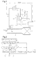
Fig. 1 is a schematic diagram showing the structure of an injection valve in relation with an exhaust purification device of an internal combustion engine according to one embodiment of the present invention. -
Fig. 2 is a flowchart showing the procedures for executing heating control on a urea solution in the embodiment. -
Fig. 3 is a flowchart showing the procedures for executing pressure control on the urea solution in the embodiment. -
Fig. 4 is a map showing the relationship between the temperature of the urea solution and the target pressure value of the urea solution in the embodiment. - One embodiment of the present invention will now be described with reference to
Figs. 1 to 4 . - As shown in
Fig. 1 , an exhaust purification device includes a selective reduction catalyst (hereinafter, referred to as the catalyst 4), which is arranged in anexhaust passage 2 of an internal combustion engine, and aninjection valve 14, which is arranged at the upstream side of thecatalyst 4 in theexhaust passage 2 and which injects a urea solution. - A
supply device 10, which supplies theinjection valve 14 with the urea solution, will now be described. - The
supply device 10 includes atank 11, which stores the liquid urea solution, asupply passage 12, which connects theinjection valve 14 to the inside of thetank 11, and anelectric pump 13, which is connected to thesupply passage 12. - The
pump 13, which is arranged inside thetank 11, draws in the urea solution inside thetank 11 and discharges the urea solution to theinjection valve 14. Further, thepump 13 is capable of changing the discharge amount of thepump 13 by changing a driving mode of thepump 13, more specifically, by changing the rotation speed of an output shaft of the pump 13 (hereinafter, referred to as pump rotation speed). By changing the discharge amount of thepump 13, the pressure of the urea solution injected from theinjection valve 14 may be changed. - A
return passage 15 branches and extends from an intermediate location of thesupply passage 12. A distal end of thereturn passage 15 opens in thetank 11. Apressure relief valve 16 is arranged at an intermediate location in thereturn passage 15. Thepressure relief valve 16 opens when the pressure of the urea solution in thesupply passage 12 increases to an upper limit pressure or higher. Thepressure relief valve 16 maintains the pressure of the urea solution in thesupply passage 12 at the upper limit pressure or lower. - Additionally, an
electrical heating device 20, which heats the urea solution in thesupply passage 12, is arranged at an intermediate location in thesupply passage 12. Theheating device 20 is arranged to cover the circumference of thesupply passage 12. - An
electronic control unit 30, which functions as a controller, performs various controls including a pump rotation speed control, a control for injecting the urea solution from theinjection valve 14, and a control for heating the urea solution with theheating device 20. Theelectronic control unit 30 is configured to include a central processing unit (CPU), which performs calculations related to various controls, a read-only memory (ROM), which stores programs and data for various controls, a random access memory (RAM), which temporarily stores calculation results or the like, and the like. Theelectronic control unit 30 reads detection signals from various sensors, performs various calculations, and controls the engine based on the calculation results. - In addition to known sensors used for recognizing the engine operation condition, the various sensors includes a
temperature sensor 31, which detects the temperature Turea of the urea solution in thesupply passage 12, and apressure sensor 32, which detects the pressure Purea of the urea solution in thesupply passage 12. Thetemperature sensor 31 is located at the downstream side of theheating device 20 in thesupply passage 12. Thepressure sensor 32 is arranged at the downstream side of thepump 13 in thesupply passage 12. - In the present embodiment, the
heating device 20 heats the urea solution in thesupply passage 12 until just before the urea solution is vaporized. This enhances the vaporization of the urea solution injected into theexhaust passage 2 and increases the NOx removal rate. - The procedures for executing heating control on the urea solution will now be described with reference to the flowchart in
Fig. 2 . The series of processes shown inFig. 2 is repeatedly executed by theelectronic control unit 30 in a predetermined cycle when the engine is running. - As shown in
Fig. 2 , in the series of processes, first, it is determined whether or not the urea solution temperature Turea detected by thetemperature sensor 31 is less than an upper limit temperature α (step S1). The upper limit temperature α is slightly lower than the boiling temperature of the urea solution and set in advance based on experiments or the like. If the urea solution temperature Turea is less than the upper limit temperature α (step S1: YES), in step S2, it is determined whether or not an energizing duration time Δt is shorter than an upper limit time Δta. The energizing duration time Δt is the time during which theheating device 20 is continuously energized until the present time. - Initially, in the determination process of step S2, the energizing duration time Δt is less than the upper limit time Δta. Thus, a positive determination is made (step S2: YES). Next, in step S3, the
heating device 20 is energized. Then, the series of processes is temporarily terminated. - If the energizing duration time Δt is longer than or equal to the upper limit time Δta, in the determination process of step S2, a negative determination is made (step S2: NO). Next, in step S4, the energizing of the
heating device 20 is stopped. Then, the series of processes is temporarily terminated. - Further, if the urea solution temperature Turea is higher than or equal to the upper limit temperature α (step S1: NO), in step S4, the energizing of the
heating device 20 is stopped to lower the urea solution temperature Turea. Then, the series of processes is temporarily terminated. - As described above, when the urea solution is heated and injected in this manner, the urea solution may be vaporized the moment the urea solution is injected into the
exhaust passage 2. This decreases the mass of each particle in the atomized urea solution and lowers the spray penetration. As a result, the urea solution remains around aninjection outlet 14a of theinjection valve 14. This leads to a problem in which there is a tendency of urea depositions formed around theinjection outlet 14a. - To cope with this problem, in the present embodiment, when the urea solution is injected from the
injection valve 14, the urea solution is heated by theheating device 20 and, when the urea solution temperature Turea is high, the urea solution injected from theinjection valve 14 is raised to a higher pressure by thepump 13 than when the temperature is low. This enhances the vaporization of the urea solution and limits the urea deposition formed around theinjection outlet 14a of theinjection valve 14. - The procedures for executing pressure control on the urea solution will now be described with reference to the flowchart of
Fig. 3 . The series of processes shown inFig. 3 is repeatedly executed by theelectronic control unit 30 in a predetermined cycle when the engine is running.Fig. 4 is a map showing the relationship of the temperature Turea of the urea solution supplied to theinjection valve 14 and the target pressure value Pureatrg of the urea solution supplied to theinjection valve 14 in correspondence with the urea solution temperature Turea. - As shown in
Fig. 3 , in the series of processes, first, the urea solution temperature Turea detected by thetemperature sensor 31 is read (step S11). Next, in step S12, with reference to the map shown inFig. 4 , the target pressure value Pureatrg of the urea solution is set based on the read urea solution temperature Turea. As shown inFig. 4 , the target pressure value Pureatrg of the urea solution is increased as the urea solution temperature Turea increases. - In this manner, when the target pressure value Pureatrg of the urea solution is set, in step S13, the pump rotation speed is set based on the difference of the actual urea solution pressure Purea detected by the
pressure sensor 32 and the above target value Pureatrg. Then, the series of processes is temporarily terminated. More specifically, the pump rotation speed is feedback-controlled so that the above difference becomes zero, that is, the pressure of the urea solution provided to theinjection valve 14 becomes equal to the target pressure value Pureatrg of the urea solution. - The operation of the present embodiment will now be described.
- When the urea solution is injected into the
exhaust passage 2 through theinjection valve 14, the hot exhaust hydrolyzes the urea solution and generates ammonia. The ammonia (NH3) reduces the nitrogen oxide (NOx) suspended in the exhaust and generates nitrogen (N2) and water (H2O). In this manner, the NOx is removed. - In this case, the urea solution supplied to the
injection valve 14 is heated by theheating device 20 until just before being vaporized. This enhances the vaporization of the urea solution and increases the NOx removal rate. - Further, the pressure of the urea solution that is injected is raised as the urea solution temperature Turea increases. Thus, a decrease in the spray penetration of the injected urea solution is limited. This reduces the urea solution remained around the
injection outlet 14a of theinjection valve 14 and limits urea depositions around theinjection outlet 14a of theinjection valve 14. - In the present embodiment described above, the
pump 13 corresponds to the variable pressure mechanism of the present invention, and theinjection valve 14 corresponds to the injection mechanism of the present invention. - The exhaust purification device of the internal combustion engine of the present embodiment described above obtains following advantages (1) to (4).
- (1) The exhaust purification device of the internal combustion engine injects the urea solution from the
injection valve 14 into theexhaust passage 2 at the upstream side of thecatalyst 4 to remove nitrogen oxide and purify the exhaust. Further, theheating device 20 heats the urea solution supplied to theinjection valve 14. Also, thepump 13, which changes the pressure of the urea solution supplied to theinjection valve 14, varies the pressure of the urea solution that is injected from theinjection valve 14. When injecting the urea solution from theinjection valve 14, theelectronic control unit 30 heats the urea solution with theheating device 20. Further, theelectronic control unit 30 increases the pressure of the urea solution when the temperature of the urea solution Turea is high as compared to when the temperature is low. This configuration enhances the vaporization of the urea solution and limits the formation of urea deposition around theinjection outlet 14a of theinjection valve 14. Further, theinjection valve 14 does not have to function to vary the pressure of the urea solution. This simplifies the configuration of theinjection valve 14. - (2) The
pressure sensor 32 detects the pressure Purea of the urea solution supplied to theinjection valve 14. Theelectronic control unit 30 changes the pressure of the urea solution supplied to theinjection valve 14 by controlling the driving mode of thepump 13 based on the detection result of thepressure sensor 32. This configuration allows for fine control of the driving mode of thepump 13 based on the actual pressure Purea of the urea solution supplied to theinjection valve 14 and accurate control of the pressure of the urea solution injected from theinjection valve 14. - (3) The
electronic control unit 30 includes the map defining the relationship of the temperature Turea of the urea solution supplied to theinjection valve 14 and the target pressure value Pureatrg of the urea solution supplied to theinjection valve 14 corresponding to the urea solution temperature Turea. Theelectronic control unit 30 controls the driving mode of thepump 13 so that the pressure of the urea solution supplied to theinjection valve 14 becomes equal to the target pressure value Pureatrg of the urea solution. In this configuration, by using the corresponding relationship of the predetermined urea solution temperature Turea and the target pressure value Pureatrg of the urea solution, the target pressure value Pureatrg of the urea solution may be easily and accurately set based on the urea solution temperature Turea. Then, by controlling the driving mode of thepump 13 based on the target pressure value Pureatrg of the urea solution, which is set in the above manner, the actual pressure of the urea solution may be controlled in a preferred manner. - (4) The
temperature sensor 31 detects the urea solution temperature Turea. Theelectronic control unit 30 changes the pressure of the urea solution injected from theinjection valve 14 by controlling the driving mode of thepump 13 based on the detection result of thetemperature sensor 31. This configuration allows for fine control of the driving mode of thepump 13 based on the actual pressure Purea of the urea solution and accurate control of the pressure of the urea solution injected from theinjection valve 14. - The exhaust purification device of the internal combustion engine of the present invention is not limited to the configuration illustrated in the above embodiment and may be modified, for example, as described below.
- In the above embodiment, the
temperature sensor 31 detects the urea solution temperature Turea in thesupply passage 12. However, the present invention is not limited to this configuration. For example, the temperature of the urea solution may be estimated from the amount of heat applied to the urea solution by theheating device 20, the amount of the urea solution existing in thesupply device 10, the ambient temperature of the urea solution, or the like. - In the above embodiment, the target pressure value Pureatrg of the urea solution is set by referring to the map. Instead, the target pressure value Pureatrg of the urea solution may be calculated using a function.
- In the above embodiment, the
pressure sensor 32 directly detects the urea solution pressure Purea in thesupply passage 12. However, the present invention is not limited to this configuration. For example, the relationship of the pump rotation speed and the urea solution pressure may be obtained from experiments or the like in advance, and a target value of the pump rotation speed may be set based on the urea solution temperature Turea. In this case, also, the pressure of the urea solution injected from theinjection valve 14 may be changed in accordance with the urea solution temperature Turea. - In the above embodiment, the pressure of the urea solution supplied to the
injection valve 14 is changed by controlling the pump rotation speed. In addition, the pressure of the urea solution supplied to theinjection valve 14 may be changed by the pressure of thepressure relief valve 16 when open. - The above embodiment and the modified examples illustrate a variable pressure mechanism that varies the pressure of the urea solution supplied to the
injection valve 14. However, the variable pressure mechanism of the present invention is not limited to this configuration. More specifically, an injection mechanism that includes a variable pressure function may also be employed. - The above embodiment and the modified examples illustrate the exhaust purification device that injects the urea solution from the injection mechanism at the upstream side of the
catalyst 4. However, the liquid additive agent of the present invention is not limited to a urea solution. It is only necessary that a liquid additive agent is injected from the injection mechanism at the upstream side of the catalyst to purify the exhaust. -
- 2
- Exhaust Passage
- 4
- Catalyst
- 10
- Supply Device
- 11
- Tank
- 12
- Supply Passage
- 13
- Pump (Variable Pressure Mechanism)
- 14
- Injection Valve (Injection Mechanism)
- 14a
- Injection Outlet
- 15
- Return Passage
- 16
- Pressure Relief Valve
- 20
- Heating Device
- 30
- Electronic Control Unit
- 31
- Temperature Sensor
- 32
- Pressure Sensor
Claims (7)
- An exhaust purification device for an internal combustion engine that includes an exhaust passage including a catalyst, the exhaust purification device comprising:an injection mechanism that injects a liquid additive agent into the exhaust passage at an upstream side of the catalyst to purify exhaust;a heating device that heats the additive agent supplied to the injection mechanism; anda variable pressure mechanism that varies pressure of the additive agent, which is injected from the injection mechanism, whereinthe heating device heats the additive agent when the additive agent is injected from the injection mechanism, and the variable pressure mechanism increases the pressure of the additive agent, which is injected from the injection mechanism, when temperature of the additive agent is high as compared to when the temperature is low.
- The exhaust purification device for an internal combustion engine according to claim 1, wherein the variable pressure mechanism varies the pressure of the additive agent supplied to the injection mechanism.
- The exhaust purification device for an internal combustion engine according to claim 2, wherein the variable pressure mechanism is a pump that draws in the additive agent from a tank, which stores the additive agent, discharges the additive agent toward the injection mechanism, and is capable of changing a discharge amount of the pump.
- The exhaust purification device for an internal combustion engine according to claim 2 or 3, comprising:a pressure sensor that detects the pressure of the additive agent, which is supplied to the injection mechanism; anda controller that controls the variable pressure mechanism based on a detection result of the pressure sensor to change the pressure of the additive agent, which is supplied to the injection mechanism.
- The exhaust purification device for an internal combustion engine according to claim 4, wherein
a relationship of the temperature of the additive agent, which is supplied to the injection mechanism, and a target pressure value of the additive agent, which is supplied to the injection mechanism, at the temperature is determined in advance, and
the controller controls the variable pressure mechanism so that the pressure of the additive agent, which is supplied to the injection mechanism, becomes equal to the target value. - The exhaust purification device for an internal combustion engine according to any one of claims 1 to 5, comprising:a temperature sensor that detects the temperature of the additive agent; anda controller that controls the variable pressure mechanism based on a detection result of the temperature sensor to change the pressure of the additive agent, which is injected from the injection mechanism.
- The exhaust purification device for an internal combustion engine according to any one of claims 1 to 6, wherein the additive agent is a urea solution.
Applications Claiming Priority (1)
| Application Number | Priority Date | Filing Date | Title |
|---|---|---|---|
| PCT/JP2012/059716 WO2013153606A1 (en) | 2012-04-09 | 2012-04-09 | Exhaust purification device for internal combustion engine |
Publications (3)
| Publication Number | Publication Date |
|---|---|
| EP2837784A1 true EP2837784A1 (en) | 2015-02-18 |
| EP2837784A4 EP2837784A4 (en) | 2015-05-06 |
| EP2837784B1 EP2837784B1 (en) | 2017-07-12 |
Family
ID=49327216
Family Applications (1)
| Application Number | Title | Priority Date | Filing Date |
|---|---|---|---|
| EP12874118.8A Not-in-force EP2837784B1 (en) | 2012-04-09 | 2012-04-09 | Exhaust purification device for internal combustion engine |
Country Status (3)
| Country | Link |
|---|---|
| EP (1) | EP2837784B1 (en) |
| JP (1) | JP5904274B2 (en) |
| WO (1) | WO2013153606A1 (en) |
Cited By (2)
| Publication number | Priority date | Publication date | Assignee | Title |
|---|---|---|---|---|
| EP3135878A1 (en) * | 2015-08-28 | 2017-03-01 | General Electric Company | Treatment of emissions in power plants |
| US11143077B2 (en) | 2015-10-08 | 2021-10-12 | Cummins Emission Solutions Inc. | System and method for varying reductant delivery pressure to aftertreatment systems |
Families Citing this family (4)
| Publication number | Priority date | Publication date | Assignee | Title |
|---|---|---|---|---|
| JP6631479B2 (en) * | 2016-02-19 | 2020-01-15 | トヨタ自動車株式会社 | Abnormal diagnosis device for exhaust gas purification device of internal combustion engine |
| JP6885708B2 (en) * | 2016-11-10 | 2021-06-16 | トヨタ自動車株式会社 | Exhaust purification device for internal combustion engine |
| CN107387214A (en) * | 2017-08-11 | 2017-11-24 | 天纳克(苏州)排放系统有限公司 | Built-in urea feedway |
| CN119616637B (en) * | 2025-02-17 | 2025-06-24 | 潍柴动力股份有限公司 | Urea pump pressure control method and control device for hybrid vehicle and electronic equipment |
Family Cites Families (10)
| Publication number | Priority date | Publication date | Assignee | Title |
|---|---|---|---|---|
| JPH0715254B2 (en) * | 1989-06-30 | 1995-02-22 | 神鋼電機株式会社 | Exhaust gas denitration device |
| AU5618598A (en) * | 1996-12-20 | 1998-07-17 | Clean Diesel Technologies, Inc. | Method and apparatus for reducing harmful emissions from a lean-burn engine by urea injection scr |
| JP2006233936A (en) * | 2005-02-28 | 2006-09-07 | Mitsubishi Fuso Truck & Bus Corp | Exhaust gas purification device for internal combustion engine |
| US20070119153A1 (en) * | 2005-11-29 | 2007-05-31 | Pierz Patrick M | Superheated urea injection for aftertreatment applications |
| JP4708320B2 (en) * | 2006-12-01 | 2011-06-22 | ボッシュ株式会社 | NOX purification device |
| JP4867675B2 (en) * | 2007-01-23 | 2012-02-01 | 株式会社デンソー | Reducing agent supply device |
| JP2008196375A (en) * | 2007-02-13 | 2008-08-28 | Toyota Motor Corp | Exhaust gas purification device for internal combustion engine |
| JP4558816B2 (en) * | 2008-06-05 | 2010-10-06 | 株式会社日本自動車部品総合研究所 | Exhaust gas purification device for internal combustion engine |
| JP2010065581A (en) | 2008-09-10 | 2010-03-25 | Denso Corp | Exhaust emission control system of internal combustion engine |
| JP2013142309A (en) * | 2012-01-10 | 2013-07-22 | Toyota Motor Corp | Exhaust emission control device for internal combustion engine |
-
2012
- 2012-04-09 EP EP12874118.8A patent/EP2837784B1/en not_active Not-in-force
- 2012-04-09 JP JP2014509924A patent/JP5904274B2/en active Active
- 2012-04-09 WO PCT/JP2012/059716 patent/WO2013153606A1/en not_active Ceased
Cited By (2)
| Publication number | Priority date | Publication date | Assignee | Title |
|---|---|---|---|---|
| EP3135878A1 (en) * | 2015-08-28 | 2017-03-01 | General Electric Company | Treatment of emissions in power plants |
| US11143077B2 (en) | 2015-10-08 | 2021-10-12 | Cummins Emission Solutions Inc. | System and method for varying reductant delivery pressure to aftertreatment systems |
Also Published As
| Publication number | Publication date |
|---|---|
| WO2013153606A1 (en) | 2013-10-17 |
| JP5904274B2 (en) | 2016-04-13 |
| JPWO2013153606A1 (en) | 2015-12-17 |
| EP2837784B1 (en) | 2017-07-12 |
| EP2837784A4 (en) | 2015-05-06 |
Similar Documents
| Publication | Publication Date | Title |
|---|---|---|
| EP2837784A1 (en) | Exhaust purification device for internal combustion engine | |
| CN101542081B (en) | Method for operating a reagent metering valve and device for carrying out the method | |
| JP5912232B2 (en) | SCR system | |
| JP6087580B2 (en) | Exhaust purification device for internal combustion engine and exhaust purification method thereof | |
| US10337435B2 (en) | Heater control device for exhaust gas sensor | |
| EP3009621A1 (en) | Device and method for controlling reducing agent supply device | |
| CN101384813A (en) | Outside air temperature detection device and exhaust purification device | |
| EP3106639B1 (en) | Reductant supply system | |
| EP2896799B1 (en) | Additive supply device | |
| EP2784279B1 (en) | Exhaust purification device for internal combustion engine | |
| JP2015151978A (en) | Controller for exhaust emission control device | |
| JP2012127308A (en) | Reducing agent supply device, and exhaust emission control device for internal combustion engine | |
| CN104114825A (en) | Method pertaining to an SCR system and an SCR system | |
| US9567917B2 (en) | Method for controlling an engine system | |
| JP6260378B2 (en) | Control device for exhaust purification system | |
| JP6062906B2 (en) | Exhaust gas purification device for internal combustion engine | |
| JP6972878B2 (en) | Abnormality diagnosis device for exhaust gas purification device of internal combustion engine | |
| US10883404B2 (en) | Method and apparatus for controlling reductant injection into an exhaust gas feedstream of an internal combustion engine | |
| JP6574707B2 (en) | Addition control device | |
| JP6740806B2 (en) | Heating system | |
| EP2825295B1 (en) | Scr treatement of engine exhaust gases using temperature control | |
| JP2011007151A (en) | Exhaust emission control device | |
| CN111102046B (en) | Method for reducing deposits in a metering device | |
| JP2019105188A (en) | Reducing agent feeding device, exhaust emission control system and control method for reducing agent feeding device | |
| CN118686688A (en) | Method for controlling an SCR system having an intake line and a return line for an internal combustion engine |
Legal Events
| Date | Code | Title | Description |
|---|---|---|---|
| PUAI | Public reference made under article 153(3) epc to a published international application that has entered the european phase |
Free format text: ORIGINAL CODE: 0009012 |
|
| 17P | Request for examination filed |
Effective date: 20141110 |
|
| AK | Designated contracting states |
Kind code of ref document: A1 Designated state(s): AL AT BE BG CH CY CZ DE DK EE ES FI FR GB GR HR HU IE IS IT LI LT LU LV MC MK MT NL NO PL PT RO RS SE SI SK SM TR |
|
| AX | Request for extension of the european patent |
Extension state: BA ME |
|
| RA4 | Supplementary search report drawn up and despatched (corrected) |
Effective date: 20150402 |
|
| RIC1 | Information provided on ipc code assigned before grant |
Ipc: F01N 3/36 20060101ALI20150327BHEP Ipc: F01N 3/08 20060101AFI20150327BHEP Ipc: F01N 3/20 20060101ALI20150327BHEP |
|
| DAX | Request for extension of the european patent (deleted) | ||
| 17Q | First examination report despatched |
Effective date: 20160428 |
|
| STAA | Information on the status of an ep patent application or granted ep patent |
Free format text: STATUS: EXAMINATION IS IN PROGRESS |
|
| GRAP | Despatch of communication of intention to grant a patent |
Free format text: ORIGINAL CODE: EPIDOSNIGR1 |
|
| STAA | Information on the status of an ep patent application or granted ep patent |
Free format text: STATUS: GRANT OF PATENT IS INTENDED |
|
| INTG | Intention to grant announced |
Effective date: 20170201 |
|
| GRAS | Grant fee paid |
Free format text: ORIGINAL CODE: EPIDOSNIGR3 |
|
| GRAA | (expected) grant |
Free format text: ORIGINAL CODE: 0009210 |
|
| STAA | Information on the status of an ep patent application or granted ep patent |
Free format text: STATUS: THE PATENT HAS BEEN GRANTED |
|
| AK | Designated contracting states |
Kind code of ref document: B1 Designated state(s): AL AT BE BG CH CY CZ DE DK EE ES FI FR GB GR HR HU IE IS IT LI LT LU LV MC MK MT NL NO PL PT RO RS SE SI SK SM TR |
|
| REG | Reference to a national code |
Ref country code: GB Ref legal event code: FG4D |
|
| REG | Reference to a national code |
Ref country code: CH Ref legal event code: EP |
|
| REG | Reference to a national code |
Ref country code: AT Ref legal event code: REF Ref document number: 908555 Country of ref document: AT Kind code of ref document: T Effective date: 20170715 |
|
| REG | Reference to a national code |
Ref country code: IE Ref legal event code: FG4D |
|
| REG | Reference to a national code |
Ref country code: DE Ref legal event code: R096 Ref document number: 602012034586 Country of ref document: DE |
|
| REG | Reference to a national code |
Ref country code: NL Ref legal event code: MP Effective date: 20170712 |
|
| REG | Reference to a national code |
Ref country code: LT Ref legal event code: MG4D |
|
| REG | Reference to a national code |
Ref country code: AT Ref legal event code: MK05 Ref document number: 908555 Country of ref document: AT Kind code of ref document: T Effective date: 20170712 |
|
| REG | Reference to a national code |
Ref country code: DE Ref legal event code: R084 Ref document number: 602012034586 Country of ref document: DE |
|
| PG25 | Lapsed in a contracting state [announced via postgrant information from national office to epo] |
Ref country code: NL Free format text: LAPSE BECAUSE OF FAILURE TO SUBMIT A TRANSLATION OF THE DESCRIPTION OR TO PAY THE FEE WITHIN THE PRESCRIBED TIME-LIMIT Effective date: 20170712 Ref country code: NO Free format text: LAPSE BECAUSE OF FAILURE TO SUBMIT A TRANSLATION OF THE DESCRIPTION OR TO PAY THE FEE WITHIN THE PRESCRIBED TIME-LIMIT Effective date: 20171012 Ref country code: LT Free format text: LAPSE BECAUSE OF FAILURE TO SUBMIT A TRANSLATION OF THE DESCRIPTION OR TO PAY THE FEE WITHIN THE PRESCRIBED TIME-LIMIT Effective date: 20170712 Ref country code: SE Free format text: LAPSE BECAUSE OF FAILURE TO SUBMIT A TRANSLATION OF THE DESCRIPTION OR TO PAY THE FEE WITHIN THE PRESCRIBED TIME-LIMIT Effective date: 20170712 Ref country code: HR Free format text: LAPSE BECAUSE OF FAILURE TO SUBMIT A TRANSLATION OF THE DESCRIPTION OR TO PAY THE FEE WITHIN THE PRESCRIBED TIME-LIMIT Effective date: 20170712 Ref country code: FI Free format text: LAPSE BECAUSE OF FAILURE TO SUBMIT A TRANSLATION OF THE DESCRIPTION OR TO PAY THE FEE WITHIN THE PRESCRIBED TIME-LIMIT Effective date: 20170712 Ref country code: AT Free format text: LAPSE BECAUSE OF FAILURE TO SUBMIT A TRANSLATION OF THE DESCRIPTION OR TO PAY THE FEE WITHIN THE PRESCRIBED TIME-LIMIT Effective date: 20170712 |
|
| PG25 | Lapsed in a contracting state [announced via postgrant information from national office to epo] |
Ref country code: ES Free format text: LAPSE BECAUSE OF FAILURE TO SUBMIT A TRANSLATION OF THE DESCRIPTION OR TO PAY THE FEE WITHIN THE PRESCRIBED TIME-LIMIT Effective date: 20170712 Ref country code: IS Free format text: LAPSE BECAUSE OF FAILURE TO SUBMIT A TRANSLATION OF THE DESCRIPTION OR TO PAY THE FEE WITHIN THE PRESCRIBED TIME-LIMIT Effective date: 20171112 Ref country code: RS Free format text: LAPSE BECAUSE OF FAILURE TO SUBMIT A TRANSLATION OF THE DESCRIPTION OR TO PAY THE FEE WITHIN THE PRESCRIBED TIME-LIMIT Effective date: 20170712 Ref country code: PL Free format text: LAPSE BECAUSE OF FAILURE TO SUBMIT A TRANSLATION OF THE DESCRIPTION OR TO PAY THE FEE WITHIN THE PRESCRIBED TIME-LIMIT Effective date: 20170712 Ref country code: LV Free format text: LAPSE BECAUSE OF FAILURE TO SUBMIT A TRANSLATION OF THE DESCRIPTION OR TO PAY THE FEE WITHIN THE PRESCRIBED TIME-LIMIT Effective date: 20170712 Ref country code: BG Free format text: LAPSE BECAUSE OF FAILURE TO SUBMIT A TRANSLATION OF THE DESCRIPTION OR TO PAY THE FEE WITHIN THE PRESCRIBED TIME-LIMIT Effective date: 20171012 Ref country code: GR Free format text: LAPSE BECAUSE OF FAILURE TO SUBMIT A TRANSLATION OF THE DESCRIPTION OR TO PAY THE FEE WITHIN THE PRESCRIBED TIME-LIMIT Effective date: 20171013 |
|
| REG | Reference to a national code |
Ref country code: DE Ref legal event code: R097 Ref document number: 602012034586 Country of ref document: DE |
|
| PG25 | Lapsed in a contracting state [announced via postgrant information from national office to epo] |
Ref country code: CZ Free format text: LAPSE BECAUSE OF FAILURE TO SUBMIT A TRANSLATION OF THE DESCRIPTION OR TO PAY THE FEE WITHIN THE PRESCRIBED TIME-LIMIT Effective date: 20170712 Ref country code: RO Free format text: LAPSE BECAUSE OF FAILURE TO SUBMIT A TRANSLATION OF THE DESCRIPTION OR TO PAY THE FEE WITHIN THE PRESCRIBED TIME-LIMIT Effective date: 20170712 Ref country code: DK Free format text: LAPSE BECAUSE OF FAILURE TO SUBMIT A TRANSLATION OF THE DESCRIPTION OR TO PAY THE FEE WITHIN THE PRESCRIBED TIME-LIMIT Effective date: 20170712 |
|
| PLBE | No opposition filed within time limit |
Free format text: ORIGINAL CODE: 0009261 |
|
| STAA | Information on the status of an ep patent application or granted ep patent |
Free format text: STATUS: NO OPPOSITION FILED WITHIN TIME LIMIT |
|
| PG25 | Lapsed in a contracting state [announced via postgrant information from national office to epo] |
Ref country code: IT Free format text: LAPSE BECAUSE OF FAILURE TO SUBMIT A TRANSLATION OF THE DESCRIPTION OR TO PAY THE FEE WITHIN THE PRESCRIBED TIME-LIMIT Effective date: 20170712 Ref country code: SM Free format text: LAPSE BECAUSE OF FAILURE TO SUBMIT A TRANSLATION OF THE DESCRIPTION OR TO PAY THE FEE WITHIN THE PRESCRIBED TIME-LIMIT Effective date: 20170712 Ref country code: SK Free format text: LAPSE BECAUSE OF FAILURE TO SUBMIT A TRANSLATION OF THE DESCRIPTION OR TO PAY THE FEE WITHIN THE PRESCRIBED TIME-LIMIT Effective date: 20170712 Ref country code: EE Free format text: LAPSE BECAUSE OF FAILURE TO SUBMIT A TRANSLATION OF THE DESCRIPTION OR TO PAY THE FEE WITHIN THE PRESCRIBED TIME-LIMIT Effective date: 20170712 |
|
| 26N | No opposition filed |
Effective date: 20180413 |
|
| PG25 | Lapsed in a contracting state [announced via postgrant information from national office to epo] |
Ref country code: SI Free format text: LAPSE BECAUSE OF FAILURE TO SUBMIT A TRANSLATION OF THE DESCRIPTION OR TO PAY THE FEE WITHIN THE PRESCRIBED TIME-LIMIT Effective date: 20170712 |
|
| PG25 | Lapsed in a contracting state [announced via postgrant information from national office to epo] |
Ref country code: MC Free format text: LAPSE BECAUSE OF FAILURE TO SUBMIT A TRANSLATION OF THE DESCRIPTION OR TO PAY THE FEE WITHIN THE PRESCRIBED TIME-LIMIT Effective date: 20170712 |
|
| REG | Reference to a national code |
Ref country code: CH Ref legal event code: PL |
|
| REG | Reference to a national code |
Ref country code: BE Ref legal event code: MM Effective date: 20180430 |
|
| GBPC | Gb: european patent ceased through non-payment of renewal fee |
Effective date: 20180409 |
|
| REG | Reference to a national code |
Ref country code: IE Ref legal event code: MM4A |
|
| PG25 | Lapsed in a contracting state [announced via postgrant information from national office to epo] |
Ref country code: LU Free format text: LAPSE BECAUSE OF NON-PAYMENT OF DUE FEES Effective date: 20180409 |
|
| PG25 | Lapsed in a contracting state [announced via postgrant information from national office to epo] |
Ref country code: GB Free format text: LAPSE BECAUSE OF NON-PAYMENT OF DUE FEES Effective date: 20180409 Ref country code: LI Free format text: LAPSE BECAUSE OF NON-PAYMENT OF DUE FEES Effective date: 20180430 Ref country code: CH Free format text: LAPSE BECAUSE OF NON-PAYMENT OF DUE FEES Effective date: 20180430 Ref country code: BE Free format text: LAPSE BECAUSE OF NON-PAYMENT OF DUE FEES Effective date: 20180430 |
|
| PG25 | Lapsed in a contracting state [announced via postgrant information from national office to epo] |
Ref country code: FR Free format text: LAPSE BECAUSE OF NON-PAYMENT OF DUE FEES Effective date: 20180430 Ref country code: IE Free format text: LAPSE BECAUSE OF NON-PAYMENT OF DUE FEES Effective date: 20180409 |
|
| PGFP | Annual fee paid to national office [announced via postgrant information from national office to epo] |
Ref country code: DE Payment date: 20190326 Year of fee payment: 8 |
|
| PG25 | Lapsed in a contracting state [announced via postgrant information from national office to epo] |
Ref country code: MT Free format text: LAPSE BECAUSE OF NON-PAYMENT OF DUE FEES Effective date: 20180409 |
|
| PG25 | Lapsed in a contracting state [announced via postgrant information from national office to epo] |
Ref country code: TR Free format text: LAPSE BECAUSE OF FAILURE TO SUBMIT A TRANSLATION OF THE DESCRIPTION OR TO PAY THE FEE WITHIN THE PRESCRIBED TIME-LIMIT Effective date: 20170712 |
|
| PG25 | Lapsed in a contracting state [announced via postgrant information from national office to epo] |
Ref country code: PT Free format text: LAPSE BECAUSE OF FAILURE TO SUBMIT A TRANSLATION OF THE DESCRIPTION OR TO PAY THE FEE WITHIN THE PRESCRIBED TIME-LIMIT Effective date: 20170712 Ref country code: HU Free format text: LAPSE BECAUSE OF FAILURE TO SUBMIT A TRANSLATION OF THE DESCRIPTION OR TO PAY THE FEE WITHIN THE PRESCRIBED TIME-LIMIT; INVALID AB INITIO Effective date: 20120409 |
|
| PG25 | Lapsed in a contracting state [announced via postgrant information from national office to epo] |
Ref country code: CY Free format text: LAPSE BECAUSE OF FAILURE TO SUBMIT A TRANSLATION OF THE DESCRIPTION OR TO PAY THE FEE WITHIN THE PRESCRIBED TIME-LIMIT Effective date: 20170712 Ref country code: MK Free format text: LAPSE BECAUSE OF NON-PAYMENT OF DUE FEES Effective date: 20170712 |
|
| PG25 | Lapsed in a contracting state [announced via postgrant information from national office to epo] |
Ref country code: AL Free format text: LAPSE BECAUSE OF FAILURE TO SUBMIT A TRANSLATION OF THE DESCRIPTION OR TO PAY THE FEE WITHIN THE PRESCRIBED TIME-LIMIT Effective date: 20170712 |
|
| REG | Reference to a national code |
Ref country code: DE Ref legal event code: R119 Ref document number: 602012034586 Country of ref document: DE |
|
| PG25 | Lapsed in a contracting state [announced via postgrant information from national office to epo] |
Ref country code: DE Free format text: LAPSE BECAUSE OF NON-PAYMENT OF DUE FEES Effective date: 20201103 |