EP2837745A1 - Termination box or a wall bend for connecting a conduit to a tap assembly - Google Patents
Termination box or a wall bend for connecting a conduit to a tap assembly Download PDFInfo
- Publication number
- EP2837745A1 EP2837745A1 EP14177193.1A EP14177193A EP2837745A1 EP 2837745 A1 EP2837745 A1 EP 2837745A1 EP 14177193 A EP14177193 A EP 14177193A EP 2837745 A1 EP2837745 A1 EP 2837745A1
- Authority
- EP
- European Patent Office
- Prior art keywords
- fastening sleeve
- termination box
- tap
- conduit
- wall bend
- Prior art date
- Legal status (The legal status is an assumption and is not a legal conclusion. Google has not performed a legal analysis and makes no representation as to the accuracy of the status listed.)
- Granted
Links
Images

Classifications
-
- E—FIXED CONSTRUCTIONS
- E03—WATER SUPPLY; SEWERAGE
- E03C—DOMESTIC PLUMBING INSTALLATIONS FOR FRESH WATER OR WASTE WATER; SINKS
- E03C1/00—Domestic plumbing installations for fresh water or waste water; Sinks
- E03C1/02—Plumbing installations for fresh water
- E03C1/021—Devices for positioning or connecting of water supply lines
-
- F—MECHANICAL ENGINEERING; LIGHTING; HEATING; WEAPONS; BLASTING
- F16—ENGINEERING ELEMENTS AND UNITS; GENERAL MEASURES FOR PRODUCING AND MAINTAINING EFFECTIVE FUNCTIONING OF MACHINES OR INSTALLATIONS; THERMAL INSULATION IN GENERAL
- F16L—PIPES; JOINTS OR FITTINGS FOR PIPES; SUPPORTS FOR PIPES, CABLES OR PROTECTIVE TUBING; MEANS FOR THERMAL INSULATION IN GENERAL
- F16L21/00—Joints with sleeve or socket
- F16L21/08—Joints with sleeve or socket with additional locking means
-
- F—MECHANICAL ENGINEERING; LIGHTING; HEATING; WEAPONS; BLASTING
- F16—ENGINEERING ELEMENTS AND UNITS; GENERAL MEASURES FOR PRODUCING AND MAINTAINING EFFECTIVE FUNCTIONING OF MACHINES OR INSTALLATIONS; THERMAL INSULATION IN GENERAL
- F16L—PIPES; JOINTS OR FITTINGS FOR PIPES; SUPPORTS FOR PIPES, CABLES OR PROTECTIVE TUBING; MEANS FOR THERMAL INSULATION IN GENERAL
- F16L25/00—Construction or details of pipe joints not provided for in, or of interest apart from, groups F16L13/00 - F16L23/00
- F16L25/0036—Joints for corrugated pipes
- F16L25/0045—Joints for corrugated pipes of the quick-acting type
Definitions
- the invention relates to a termination box or wall bend for connecting a conduit to a tap assembly, said termination box or wall bend comprising a body inside of which a tap elbow or tap fitting is mountable, which conduit comprises an inner utility pipe and an outer protective pipe, the protective pipe being provided with circumferential grooves on the outer face of it, the conduit being connectable to the tap elbow or tap fitting with a fastening sleeve, and the tap assembly being connectable to the tap elbow through a bushing or corresponding tunnel, said tap elbow being locked in place by a lid.
- Water conduits in buildings are quite commonly connected to tap assemblies mounted on a wall surface by tap elbows or tap fittings.
- tap elbows or tap fittings When conduits are mounted inside the wall structure it is extremely important that the conduit is connected to the tap elbow or corresponding tap fitting and further to the tap assembly so that the connections are watertight to prevent water leakage and damages caused by such leakages. Therefore the tap elbow / tap fitting is placed in a termination box and the water conduit is placed in a protective pipe to form a double wall structure (so-called pipe-in-pipe structure).
- This kind of mounting construction is quite well protected against leakages but however it may also cause some problems.
- termination boxes must be designed so that they are able to receive various size conduits. It is not practical to design a termination box just for one conduit size. Due to this current pipe-in-pipe termination box systems have several sealings for different size conduits. This causes confusion and extra work for installers because they must select a correct sealing for each case and ensure the correct positioning of the sealing. Several sealings create also extra costs in investments and they are very sensible for conduit designs and tolerances in mountings.
- the tap elbow is placed inside the termination box.
- the tap elbow is locked in place in a closed position by a lid.
- the lid comprises normally a base part and a sealing part.
- the sealing part seals the base part against the body part of the termination box as well as against the tap elbow.
- Both the body part of the termination box and the base part of the lid are provided with threads.
- the lid is mounted in its place by turning it in the threads.
- First one of the threads is provided with a nodule and respectively a groove is formed in the other thread, so that said nodule fits in said groove locking the lid in its place.
- a disadvantage for this arrangement is that the nodule may be cut off, even when installed once. This may cause a risk of opening the thread over the years.
- the objective of the present invention is to provide a novel and improved termination box or wall bend for connecting a conduit to a tap assembly.
- the inventive termination box / wall bend is mainly characterized in that the fastening sleeve is provided with a conduit locking mechanism formed of protrusions extending towards the inside of the fastening sleeve to grip to the grooves of the protective pipe, and a flexible sealing part arranged inside the fastening sleeve, which sealing part comprises a flexible conduit sealing resting, when the termination box or wall bend is in use and the protective pipe is received within the fastening sleeve, against the outer surface of the protective pipe for sealing the same and a sealing section for sealing the fastening sleeve to the body of the termination box or wall bend.
- the protrusions of the locking mechanism are flexible in the radial direction of the fastening sleeve to allow conduits of various sizes to be received in the fastening sleeve and stiff in the axial direction of the fastening sleeve to prevent the conduit to be pulled out of the fastening sleeve when the protrusions are gripped to the grooves of the protective pipe.
- the flexible conduit sealing is arranged to receive and seal conduits of various sizes.
- the flexible sealing part further comprises a spring element extending between the protrusions of the locking mechanism and the inner side of the fastening sleeve for supporting flexibly the locking mechanism.
- the locking mechanism can be formed as an integral part of the fastening sleeve or as a separate piece mounted in the fastening sleeve.
- the lid locking the tap elbow or tap fitting in place in the body of the termination box or wall bend is provided with a bayonet connection arrangement comprising thread-like bayonet elements arranged on the outer circumferential face of the lid, each of which elements are provided with a notch, and in an inner circumferential face of an opening in the body of the termination box or wall bend counter elements for the bayonet elements are arranged to guide the lid in its place when the lid is turned either clockwise or counter clockwise.
- a sealing element made of compressible material can be arranged to create a force pushing the lid outwards and keeping the counter elements of the body in the notches of the bayonet elements. Similar spring like effect can be arranged by other means as well, e.g. separate part or having it in the tunnel or body. Sealing element itself can be positioned also other locations as only in back side.
- the present invention provides considerable advantages over the prior art.
- the sealing arrangement for connecting a conduit to the termination box or wall bend there is no need for different sealings for different size conduits, but the sealing included in the inventive arrangement fits for various conduit sizes. So the installation work is easier and simpler than before.
- the sealing arrangement resists effectively the force of pulling out the conduit because a separate mechanical locking system is integrated in the arrangement.
- a bayonet arrangement in the lid is used instead of the nodule and groove system of the prior art. This makes the installation simple and secured, which can also easily be reopened when needed.
- the present invention is directed to handle and solve the problems relating to the sealing of the connection between a conduit and a termination box or a wall bend and to the fixing of a tap elbow or a tap fitting in said termination box.
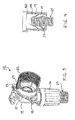
- the drawing shows a termination box, inside of which a tap elbow is mounted.
- the invention relates also to a wall bend, where the conduit and/or media pipe is bend 90 deg and fixed to wall by wall bend supports and media pipe by straight connector, i.e. by a tap fitting. This applies to all termination box and tap fitting definitions.
- the termination box is generally denoted with the reference numeral 10.
- the termination box 10 is mounted inside a wall structure of a building (not shown) to connect a conduit 25 to a tap assembly (not shown) and it comprises a body 11 inside of which a tap elbow 12 is mounted.
- the conduit 25 is connected to the tap elbow 12 with a fastening sleeve 16, and the tap assembly will be connected to the tap elbow through a bushing 22 or corresponding tunnel.
- the bushing 22 or tunnel may be integral with the body 11, or as shown in the drawing, it may be a separate component provided with threads 23, with which it can be mounted in place and taken away if needed.
- the bushing 22 or tunnel is a separate component it is preferable to use a sealing 24 between the bushing 22 or tunnel and the body 11 of the termination box 10.
- the conduit 25 is a pipe-in-pipe structure comprising an inner pipe 26a which is the utility pipe for liquid and an outer pipe 26b which is the protective pipe.
- the protective pipe 26b is provided with circumferential grooves 26c.
- the inner utility pipe 26a is connected in a normal way to the pipe joint part on the tap elbow 12 and the outer protective pipe 26b is tightened in its place with the fastening sleeve 16.
- the fastening sleeve 16 is provided with a conduit locking mechanism 17 formed of protrusions extending towards the inside of the fastening sleeve 16 so that said protrusions grip to the grooves 26c of the protective pipe 26b.
- the protrusions are so flexible that they allow the conduit 25 to be pushed through the fastening sleeve 16 in one direction towards the tap elbow 12. On the other hand they are so stiff that when gripped to the grooves 26c they prevent the conduit 25 to be pulled out of the fastening sleeve 16 in the opposite direction.
- the fastening sleeve 16 is turned in its place by threads 16a arranged both on the body 11 and the fastening sleeve 16.
- a flexible sealing part 18 is arranged inside the fastening sleeve 16 , which sealing part 18 comprises a flexible conduit sealing 19 through which the protective pipe 26b is pushed.
- the conduit sealing 19 rests against the outer surface of the protective pipe 26b.
- the sealing part 18 further comprises a sealing section 20 for the body 11 of the termination box.
- the fastening sleeve 16 is mounted in its place said sealing section 20 is squeezed against the body 11, whereby the fastening sleeve 16 also carries loads and the fastening sleeve 16 and the body 11 form a relatively rigid and integral piece.
- the conduit locking mechanism 17 i.e. the protrusions flexible enough for larger conduit dimensions, as seen in Fig.
- a spring element 21 is formed in the sealing part 18, which spring element 21 extends between the protrusions of the locking mechanism 17 and the inner side of the fastening sleeve 16. Said spring element 21 supports flexibly the locking mechanism 17. It is shown in the drawing that the locking mechanism 17 is an integral part of the fastening sleeve. However, as shown in Fig. 4 , the locking mechanism 27 can be made as a separate piece mounted inside the fastening sleeve 16. In such case the sealing part 18 pushes the locking mechanism 27 in its place.
- An advantage of a separate locking mechanism is that it gives more flexibility to move the conduit 25 towards the body 11 of the termination box and away from it.
- the tap elbow 12 is locked in place in the body 11 of the termination box 10 with a lid 13 provided with a bayonet connection arrangement.
- a lid 13 provided with a bayonet connection arrangement.
- bayonet elements On the outer circumferential face of the lid 13 thread-like bayonet elements are arranged, each of which elements are provided with a notch 15.
- counter elements for the bayonet elements are arranged guiding the lid 13 in its place when the lid 13 is turned clockwise. Said counter elements may simply be round dowels.
- sealing element 14 made of compressible material, e.g. rubber or corresponding, is arranged between the body 11 of the termination box 10 and the back side of the lid 13 .
- Said sealing element 14 creates a force pushing the lid 13 outwards and thereby keeping the counter elements of the body in the notches 15 of the bayonet elements.
- the installation of the lid 13 is simple and secured, and the lid 13 can also easily be reopened when needed.
Landscapes
- Engineering & Computer Science (AREA)
- General Engineering & Computer Science (AREA)
- Mechanical Engineering (AREA)
- Health & Medical Sciences (AREA)
- Life Sciences & Earth Sciences (AREA)
- Hydrology & Water Resources (AREA)
- Public Health (AREA)
- Water Supply & Treatment (AREA)
- Laying Of Electric Cables Or Lines Outside (AREA)
- Quick-Acting Or Multi-Walled Pipe Joints (AREA)
- Domestic Plumbing Installations (AREA)
Abstract
Description
- The invention relates to a termination box or wall bend for connecting a conduit to a tap assembly, said termination box or wall bend comprising a body inside of which a tap elbow or tap fitting is mountable, which conduit comprises an inner utility pipe and an outer protective pipe, the protective pipe being provided with circumferential grooves on the outer face of it, the conduit being connectable to the tap elbow or tap fitting with a fastening sleeve, and the tap assembly being connectable to the tap elbow through a bushing or corresponding tunnel, said tap elbow being locked in place by a lid.
- Water conduits in buildings are quite commonly connected to tap assemblies mounted on a wall surface by tap elbows or tap fittings. When conduits are mounted inside the wall structure it is extremely important that the conduit is connected to the tap elbow or corresponding tap fitting and further to the tap assembly so that the connections are watertight to prevent water leakage and damages caused by such leakages. Therefore the tap elbow / tap fitting is placed in a termination box and the water conduit is placed in a protective pipe to form a double wall structure (so-called pipe-in-pipe structure). This kind of mounting construction is quite well protected against leakages but however it may also cause some problems.
- Because different conduit sizes may be used in different installations termination boxes must be designed so that they are able to receive various size conduits. It is not practical to design a termination box just for one conduit size. Due to this current pipe-in-pipe termination box systems have several sealings for different size conduits. This causes confusion and extra work for installers because they must select a correct sealing for each case and ensure the correct positioning of the sealing. Several sealings create also extra costs in investments and they are very sensible for conduit designs and tolerances in mountings.
- As mentioned above the tap elbow is placed inside the termination box. In some current termination box designs the tap elbow is locked in place in a closed position by a lid. The lid comprises normally a base part and a sealing part. The sealing part seals the base part against the body part of the termination box as well as against the tap elbow. Both the body part of the termination box and the base part of the lid are provided with threads. The lid is mounted in its place by turning it in the threads. First one of the threads is provided with a nodule and respectively a groove is formed in the other thread, so that said nodule fits in said groove locking the lid in its place. A disadvantage for this arrangement is that the nodule may be cut off, even when installed once. This may cause a risk of opening the thread over the years.
- The objective of the present invention is to provide a novel and improved termination box or wall bend for connecting a conduit to a tap assembly. To this end the inventive termination box / wall bend is mainly characterized in that the fastening sleeve is provided with a conduit locking mechanism formed of protrusions extending towards the inside of the fastening sleeve to grip to the grooves of the protective pipe, and a flexible sealing part arranged inside the fastening sleeve, which sealing part comprises a flexible conduit sealing resting, when the termination box or wall bend is in use and the protective pipe is received within the fastening sleeve, against the outer surface of the protective pipe for sealing the same and a sealing section for sealing the fastening sleeve to the body of the termination box or wall bend.
- In one embodiment of the invention, the protrusions of the locking mechanism are flexible in the radial direction of the fastening sleeve to allow conduits of various sizes to be received in the fastening sleeve and stiff in the axial direction of the fastening sleeve to prevent the conduit to be pulled out of the fastening sleeve when the protrusions are gripped to the grooves of the protective pipe. Also the flexible conduit sealing is arranged to receive and seal conduits of various sizes.
- In a further embodiment of the invention, the flexible sealing part further comprises a spring element extending between the protrusions of the locking mechanism and the inner side of the fastening sleeve for supporting flexibly the locking mechanism.
- The locking mechanism can be formed as an integral part of the fastening sleeve or as a separate piece mounted in the fastening sleeve.
- According to one aspect of the invention the lid locking the tap elbow or tap fitting in place in the body of the termination box or wall bend is provided with a bayonet connection arrangement comprising thread-like bayonet elements arranged on the outer circumferential face of the lid, each of which elements are provided with a notch, and in an inner circumferential face of an opening in the body of the termination box or wall bend counter elements for the bayonet elements are arranged to guide the lid in its place when the lid is turned either clockwise or counter clockwise.
- Between the body of the termination box or wall bend and the back side of the lid a sealing element made of compressible material can be arranged to create a force pushing the lid outwards and keeping the counter elements of the body in the notches of the bayonet elements. Similar spring like effect can be arranged by other means as well, e.g. separate part or having it in the tunnel or body. Sealing element itself can be positioned also other locations as only in back side.
- The present invention provides considerable advantages over the prior art. In the inventive sealing arrangement for connecting a conduit to the termination box or wall bend there is no need for different sealings for different size conduits, but the sealing included in the inventive arrangement fits for various conduit sizes. So the installation work is easier and simpler than before. The sealing arrangement resists effectively the force of pulling out the conduit because a separate mechanical locking system is integrated in the arrangement. In the inventive arrangement to lock the tap elbow or tap fitting in place in the termination box or wall bend a bayonet arrangement in the lid is used instead of the nodule and groove system of the prior art. This makes the installation simple and secured, which can also easily be reopened when needed.
- Other advantages and characteristic features of the invention are set out below by detailed disclosure of the invention, wherein the invention is described with reference to the figures of the accompanying drawing, to the details of which the invention is not exclusively limited.
-
-
Fig. 1 shows a termination box partly in a cross-sectional view. -
Figs. 2A and 2B show how conduits of different sizes can be connected to the termination box by the inventive sealing arrangement. -
Fig. 3 shows a perspective view of the termination box. -
Fig. 4 shows in a cross-sectional view an embodiment of the sealing arrangement with a separate conduit locking mechanism. - As already explained earlier the present invention is directed to handle and solve the problems relating to the sealing of the connection between a conduit and a termination box or a wall bend and to the fixing of a tap elbow or a tap fitting in said termination box.
- The drawing shows a termination box, inside of which a tap elbow is mounted. However, it is to be understood that the invention relates also to a wall bend, where the conduit and/or media pipe is bend 90 deg and fixed to wall by wall bend supports and media pipe by straight connector, i.e. by a tap fitting. This applies to all termination box and tap fitting definitions.
- In the drawing the termination box is generally denoted with the
reference numeral 10. Thetermination box 10 is mounted inside a wall structure of a building (not shown) to connect aconduit 25 to a tap assembly (not shown) and it comprises abody 11 inside of which atap elbow 12 is mounted. Theconduit 25 is connected to thetap elbow 12 with afastening sleeve 16, and the tap assembly will be connected to the tap elbow through a bushing 22 or corresponding tunnel. Thebushing 22 or tunnel may be integral with thebody 11, or as shown in the drawing, it may be a separate component provided withthreads 23, with which it can be mounted in place and taken away if needed. When thebushing 22 or tunnel is a separate component it is preferable to use a sealing 24 between the bushing 22 or tunnel and thebody 11 of thetermination box 10. - As mentioned above, the
conduit 25 is a pipe-in-pipe structure comprising an inner pipe 26a which is the utility pipe for liquid and an outer pipe 26b which is the protective pipe. The protective pipe 26b is provided withcircumferential grooves 26c. The inner utility pipe 26a is connected in a normal way to the pipe joint part on thetap elbow 12 and the outer protective pipe 26b is tightened in its place with thefastening sleeve 16. Thefastening sleeve 16 is provided with aconduit locking mechanism 17 formed of protrusions extending towards the inside of thefastening sleeve 16 so that said protrusions grip to thegrooves 26c of the protective pipe 26b. The protrusions are so flexible that they allow theconduit 25 to be pushed through thefastening sleeve 16 in one direction towards thetap elbow 12. On the other hand they are so stiff that when gripped to thegrooves 26c they prevent theconduit 25 to be pulled out of the fasteningsleeve 16 in the opposite direction. Thefastening sleeve 16 is turned in its place bythreads 16a arranged both on thebody 11 and thefastening sleeve 16. - Inside the fastening
sleeve 16 aflexible sealing part 18 is arranged, which sealingpart 18 comprises a flexible conduit sealing 19 through which the protective pipe 26b is pushed. The conduit sealing 19 rests against the outer surface of the protective pipe 26b. The sealingpart 18 further comprises asealing section 20 for thebody 11 of the termination box. When thefastening sleeve 16 is mounted in its place said sealingsection 20 is squeezed against thebody 11, whereby thefastening sleeve 16 also carries loads and thefastening sleeve 16 and thebody 11 form a relatively rigid and integral piece. In order to make theconduit locking mechanism 17, i.e. the protrusions flexible enough for larger conduit dimensions, as seen inFig. 2B , as well as stiff enough for smaller conduit dimensions, as seen inFig. 2A , aspring element 21 is formed in the sealingpart 18, which springelement 21 extends between the protrusions of thelocking mechanism 17 and the inner side of thefastening sleeve 16. Saidspring element 21 supports flexibly thelocking mechanism 17. It is shown in the drawing that thelocking mechanism 17 is an integral part of the fastening sleeve. However, as shown inFig. 4 , thelocking mechanism 27 can be made as a separate piece mounted inside thefastening sleeve 16. In such case the sealingpart 18 pushes thelocking mechanism 27 in its place. An advantage of a separate locking mechanism is that it gives more flexibility to move theconduit 25 towards thebody 11 of the termination box and away from it. - As shown in
Figs. 1 and3 , in the invention thetap elbow 12 is locked in place in thebody 11 of thetermination box 10 with alid 13 provided with a bayonet connection arrangement. On the outer circumferential face of thelid 13 thread-like bayonet elements are arranged, each of which elements are provided with anotch 15. In the inner circumferential face of the opening in thebody 11 of thetermination box 10 counter elements (not shown) for the bayonet elements are arranged guiding thelid 13 in its place when thelid 13 is turned clockwise. Said counter elements may simply be round dowels. When the turning movement of thelid 13 reaches the end the counter elements in thebody 11 fall in thenotches 15 of the bayonet elements. Between thebody 11 of thetermination box 10 and the back side of the lid 13 a sealingelement 14 made of compressible material, e.g. rubber or corresponding, is arranged. Said sealingelement 14 creates a force pushing thelid 13 outwards and thereby keeping the counter elements of the body in thenotches 15 of the bayonet elements. The installation of thelid 13 is simple and secured, and thelid 13 can also easily be reopened when needed. - The invention has been described above by way of examples and with reference to the figures of the accompanying drawing. The invention is not limited merely to the examples illustrated in the figures; instead, different embodiments of the invention may vary within the scope of the inventive idea defined in the accompanying claims.
Claims (8)
- A termination box or a wall bend for connecting a conduit (25) to a tap assembly, said termination box (10) or wall bend comprising a body (11) inside of which a tap elbow (12) or a tap fitting is mountable, which conduit (25) comprises an inner utility pipe (26a) and an outer protective pipe (26b), the protective pipe (26b) being provided with circumferential grooves (26c) on the outer face of it, the conduit (25) being connected, when the termination bow or a wall bend is in use, to the tap elbow (12) or tap fitting with a fastening sleeve (16), and the tap assembly being connected, when the termination bow or a wall bend is in use,to the tap elbow (12) or tap fitting through a bushing (22) or corresponding tunnel, said tap elbow (12) or tap fitting being locked in place by a lid (13), characterized in that the fastening sleeve (16) is provided with a conduit locking mechanism (17, 27) formed of protrusions extending towards the inside of the fastening sleeve (16) to grip to the grooves (26c) of the protective pipe (26b), and a flexible sealing part (18) arranged inside the fastening sleeve (16), which sealing part (18) comprises a flexible conduit sealing (19) resting, when the termination bow or a wall bend is in use, against the outer surface of the protective pipe (26b) for sealing the same and a sealing section (20) for sealing the fastening sleeve (16) to the body (11) of the termination box (10) or wall bend.
- Termination box or wall bend as claimed in claim 1, characterized in that the protrusions of the locking mechanism (17, 27) are flexible in the radial direction of the fastening sleeve (16) to allow conduits (25) of various sizes to be received in the fastening sleeve (16) and stiff in the axial direction of the fastening sleeve (16) to prevent the conduit (25) to be pulled out of the fastening sleeve (16) when the protrusions are gripped to the grooves (26c) of the protective pipe.
- Termination box or wall bend as claimed in claim 1 or 2, characterized in that the flexible conduit sealing (19) is arranged to receive and seal conduits (25) of various sizes.
- Termination box or wall bend as claimed in any of the preceding claims, characterized in that the flexible sealing part (18) further comprises a spring element (21) extending between the protrusions of the locking mechanism (17, 27) and the inner side of the fastening sleeve (16) for supporting flexibly the locking mechanism (17, 27).
- Termination box or wall bend as claimed in any of the preceding claims, characterized in that the locking mechanism (17) is formed as an integral part of the fastening sleeve (16).
- Termination box or wall bend as claimed in any of the preceding claims, characterized in that the locking mechanism (27) is formed as a separate piece mounted in the fastening sleeve (16).
- Termination box or wall bend as claimed in any of the preceding claims, characterized in that the lid (13) locking the tap elbow (12) or tap fitting in place in the body (11) of the termination box (10) or the wall bend is provided with a bayonet connection arrangement comprising thread-like bayonet elements arranged on the outer circumferential face of the lid (13), each of which elements are provided with a notch (15), and in an inner circumferential face of an opening in the body (11) of the termination box (10) or wall bend counter elements for the bayonet elements are arranged to guide the lid (13) in its place when the lid (13) is turned either clockwise or counter clockwise.
- Termination box or wall bend as claimed in claim 7, characterized in that between the body (11) of the termination box (10) or wall bend and the back side of the lid (13) a sealing element (14) made of compressible material is arranged to create a force pushing the lid (13) outwards and keeping the counter elements of the body in the notches (15) of the bayonet elements.
Applications Claiming Priority (1)
| Application Number | Priority Date | Filing Date | Title |
|---|---|---|---|
| FI20135788A FI126096B (en) | 2013-07-19 | 2013-07-19 | Crane angle box or wall penetration for connecting a pipeline to a crane equipment |
Publications (2)
| Publication Number | Publication Date |
|---|---|
| EP2837745A1 true EP2837745A1 (en) | 2015-02-18 |
| EP2837745B1 EP2837745B1 (en) | 2018-02-07 |
Family
ID=51205264
Family Applications (1)
| Application Number | Title | Priority Date | Filing Date |
|---|---|---|---|
| EP14177193.1A Active EP2837745B1 (en) | 2013-07-19 | 2014-07-16 | Termination box or a wall bend for connecting a conduit to a tap assembly |
Country Status (4)
| Country | Link |
|---|---|
| EP (1) | EP2837745B1 (en) |
| DK (1) | DK2837745T3 (en) |
| FI (1) | FI126096B (en) |
| NO (1) | NO2837745T3 (en) |
Citations (3)
| Publication number | Priority date | Publication date | Assignee | Title |
|---|---|---|---|---|
| DE3504127A1 (en) * | 1984-02-20 | 1985-09-05 | Georg Fischer AG, Schaffhausen, CH, Niederlassung: Georg Fischer AG, 7700 Singen | Connection device for fittings |
| EP0538197A1 (en) * | 1991-10-18 | 1993-04-21 | R. Nussbaum AG | Device for connection of a flexible pipe under a wall plaster and a faucet over wall plaster (housing with flexible end position) |
| WO2001079738A1 (en) * | 2000-04-19 | 2001-10-25 | Adrian Roger Poulton | Connection device |
-
2013
- 2013-07-19 FI FI20135788A patent/FI126096B/en active IP Right Grant
-
2014
- 2014-07-16 NO NO14177193A patent/NO2837745T3/no unknown
- 2014-07-16 EP EP14177193.1A patent/EP2837745B1/en active Active
- 2014-07-16 DK DK14177193.1T patent/DK2837745T3/en active
Patent Citations (3)
| Publication number | Priority date | Publication date | Assignee | Title |
|---|---|---|---|---|
| DE3504127A1 (en) * | 1984-02-20 | 1985-09-05 | Georg Fischer AG, Schaffhausen, CH, Niederlassung: Georg Fischer AG, 7700 Singen | Connection device for fittings |
| EP0538197A1 (en) * | 1991-10-18 | 1993-04-21 | R. Nussbaum AG | Device for connection of a flexible pipe under a wall plaster and a faucet over wall plaster (housing with flexible end position) |
| WO2001079738A1 (en) * | 2000-04-19 | 2001-10-25 | Adrian Roger Poulton | Connection device |
Also Published As
| Publication number | Publication date |
|---|---|
| FI20135788L (en) | 2015-01-20 |
| DK2837745T3 (en) | 2018-05-22 |
| FI126096B (en) | 2016-06-30 |
| NO2837745T3 (en) | 2018-07-07 |
| EP2837745B1 (en) | 2018-02-07 |
Similar Documents
| Publication | Publication Date | Title |
|---|---|---|
| US7394021B2 (en) | Rotatable liquid-tight conduit connector assembly | |
| US8621683B2 (en) | Flexible drainage trap | |
| RU2436494C2 (en) | Leading-through | |
| EP2227649B1 (en) | Pipe fitting | |
| US20190013656A1 (en) | Angularly Adjustable Tubular Elbow | |
| EP2014838B1 (en) | Wall bend fixture for water pipes leading through a wall | |
| EP2837745B1 (en) | Termination box or a wall bend for connecting a conduit to a tap assembly | |
| JP5080151B2 (en) | Pipe fitting | |
| EP0325806A1 (en) | Sealed extensible coupler for connecting pipes having threaded ends, especially for containing electrical conductors | |
| EP3683369B1 (en) | A wall bend fixture and a wall bend fixture assembly | |
| EP3736478B1 (en) | Valve assembly | |
| EP2837746B1 (en) | Arrangement for installing a termination box in a wall structure | |
| KR200387795Y1 (en) | A Connection Tap | |
| JP6340828B2 (en) | header | |
| KR100743487B1 (en) | Fume pipe connector | |
| JP6235951B2 (en) | Pipe connection structure and drainage structure of sink provided with the pipe connection structure | |
| EP2656016A1 (en) | Automatic meter reading components | |
| DK178551B1 (en) | Push coupling | |
| KR200319627Y1 (en) | A coupler for the water supply pipe or drain pipe | |
| JP5645452B2 (en) | Bathroom plumbing fixtures | |
| KR100900936B1 (en) | Pipeline waterproofing device for transmission and distribution | |
| US20070246675A1 (en) | Sill cock assembly | |
| ITUB20159356A1 (en) | HYDRAULIC WALL SYSTEM WITH ANTI-ROTATION WALL OF THE HYDRAULIC COMPONENT | |
| JP2007162953A (en) | Check valve mounting structure | |
| JP2008095897A (en) | Reinforcing tool and pipe connection structure using the same |
Legal Events
| Date | Code | Title | Description |
|---|---|---|---|
| 17P | Request for examination filed |
Effective date: 20140716 |
|
| AK | Designated contracting states |
Kind code of ref document: A1 Designated state(s): AL AT BE BG CH CY CZ DE DK EE ES FI FR GB GR HR HU IE IS IT LI LT LU LV MC MK MT NL NO PL PT RO RS SE SI SK SM TR |
|
| AX | Request for extension of the european patent |
Extension state: BA ME |
|
| PUAI | Public reference made under article 153(3) epc to a published international application that has entered the european phase |
Free format text: ORIGINAL CODE: 0009012 |
|
| R17P | Request for examination filed (corrected) |
Effective date: 20150729 |
|
| RBV | Designated contracting states (corrected) |
Designated state(s): AL AT BE BG CH CY CZ DE DK EE ES FI FR GB GR HR HU IE IS IT LI LT LU LV MC MK MT NL NO PL PT RO RS SE SI SK SM TR |
|
| RAP1 | Party data changed (applicant data changed or rights of an application transferred) |
Owner name: UPONOR INNOVATION AB |
|
| GRAP | Despatch of communication of intention to grant a patent |
Free format text: ORIGINAL CODE: EPIDOSNIGR1 |
|
| INTG | Intention to grant announced |
Effective date: 20170927 |
|
| GRAS | Grant fee paid |
Free format text: ORIGINAL CODE: EPIDOSNIGR3 |
|
| GRAA | (expected) grant |
Free format text: ORIGINAL CODE: 0009210 |
|
| AK | Designated contracting states |
Kind code of ref document: B1 Designated state(s): AL AT BE BG CH CY CZ DE DK EE ES FI FR GB GR HR HU IE IS IT LI LT LU LV MC MK MT NL NO PL PT RO RS SE SI SK SM TR |
|
| REG | Reference to a national code |
Ref country code: GB Ref legal event code: FG4D |
|
| REG | Reference to a national code |
Ref country code: AT Ref legal event code: REF Ref document number: 968864 Country of ref document: AT Kind code of ref document: T Effective date: 20180215 Ref country code: CH Ref legal event code: EP |
|
| REG | Reference to a national code |
Ref country code: IE Ref legal event code: FG4D |
|
| REG | Reference to a national code |
Ref country code: DE Ref legal event code: R096 Ref document number: 602014020727 Country of ref document: DE |
|
| REG | Reference to a national code |
Ref country code: NO Ref legal event code: T2 Effective date: 20180207 |
|
| REG | Reference to a national code |
Ref country code: DK Ref legal event code: T3 Effective date: 20180515 Ref country code: SE Ref legal event code: TRGR |
|
| REG | Reference to a national code |
Ref country code: NL Ref legal event code: MP Effective date: 20180207 |
|
| REG | Reference to a national code |
Ref country code: AT Ref legal event code: MK05 Ref document number: 968864 Country of ref document: AT Kind code of ref document: T Effective date: 20180207 |
|
| PG25 | Lapsed in a contracting state [announced via postgrant information from national office to epo] |
Ref country code: FI Free format text: LAPSE BECAUSE OF FAILURE TO SUBMIT A TRANSLATION OF THE DESCRIPTION OR TO PAY THE FEE WITHIN THE PRESCRIBED TIME-LIMIT Effective date: 20180207 Ref country code: LT Free format text: LAPSE BECAUSE OF FAILURE TO SUBMIT A TRANSLATION OF THE DESCRIPTION OR TO PAY THE FEE WITHIN THE PRESCRIBED TIME-LIMIT Effective date: 20180207 Ref country code: NL Free format text: LAPSE BECAUSE OF FAILURE TO SUBMIT A TRANSLATION OF THE DESCRIPTION OR TO PAY THE FEE WITHIN THE PRESCRIBED TIME-LIMIT Effective date: 20180207 Ref country code: CY Free format text: LAPSE BECAUSE OF FAILURE TO SUBMIT A TRANSLATION OF THE DESCRIPTION OR TO PAY THE FEE WITHIN THE PRESCRIBED TIME-LIMIT Effective date: 20180207 Ref country code: ES Free format text: LAPSE BECAUSE OF FAILURE TO SUBMIT A TRANSLATION OF THE DESCRIPTION OR TO PAY THE FEE WITHIN THE PRESCRIBED TIME-LIMIT Effective date: 20180207 Ref country code: HR Free format text: LAPSE BECAUSE OF FAILURE TO SUBMIT A TRANSLATION OF THE DESCRIPTION OR TO PAY THE FEE WITHIN THE PRESCRIBED TIME-LIMIT Effective date: 20180207 |
|
| PG25 | Lapsed in a contracting state [announced via postgrant information from national office to epo] |
Ref country code: PL Free format text: LAPSE BECAUSE OF FAILURE TO SUBMIT A TRANSLATION OF THE DESCRIPTION OR TO PAY THE FEE WITHIN THE PRESCRIBED TIME-LIMIT Effective date: 20180207 Ref country code: RS Free format text: LAPSE BECAUSE OF FAILURE TO SUBMIT A TRANSLATION OF THE DESCRIPTION OR TO PAY THE FEE WITHIN THE PRESCRIBED TIME-LIMIT Effective date: 20180207 Ref country code: BG Free format text: LAPSE BECAUSE OF FAILURE TO SUBMIT A TRANSLATION OF THE DESCRIPTION OR TO PAY THE FEE WITHIN THE PRESCRIBED TIME-LIMIT Effective date: 20180507 Ref country code: AT Free format text: LAPSE BECAUSE OF FAILURE TO SUBMIT A TRANSLATION OF THE DESCRIPTION OR TO PAY THE FEE WITHIN THE PRESCRIBED TIME-LIMIT Effective date: 20180207 Ref country code: LV Free format text: LAPSE BECAUSE OF FAILURE TO SUBMIT A TRANSLATION OF THE DESCRIPTION OR TO PAY THE FEE WITHIN THE PRESCRIBED TIME-LIMIT Effective date: 20180207 Ref country code: IS Free format text: LAPSE BECAUSE OF FAILURE TO SUBMIT A TRANSLATION OF THE DESCRIPTION OR TO PAY THE FEE WITHIN THE PRESCRIBED TIME-LIMIT Effective date: 20180607 Ref country code: GR Free format text: LAPSE BECAUSE OF FAILURE TO SUBMIT A TRANSLATION OF THE DESCRIPTION OR TO PAY THE FEE WITHIN THE PRESCRIBED TIME-LIMIT Effective date: 20180508 |
|
| PG25 | Lapsed in a contracting state [announced via postgrant information from national office to epo] |
Ref country code: IT Free format text: LAPSE BECAUSE OF FAILURE TO SUBMIT A TRANSLATION OF THE DESCRIPTION OR TO PAY THE FEE WITHIN THE PRESCRIBED TIME-LIMIT Effective date: 20180207 Ref country code: RO Free format text: LAPSE BECAUSE OF FAILURE TO SUBMIT A TRANSLATION OF THE DESCRIPTION OR TO PAY THE FEE WITHIN THE PRESCRIBED TIME-LIMIT Effective date: 20180207 Ref country code: EE Free format text: LAPSE BECAUSE OF FAILURE TO SUBMIT A TRANSLATION OF THE DESCRIPTION OR TO PAY THE FEE WITHIN THE PRESCRIBED TIME-LIMIT Effective date: 20180207 Ref country code: AL Free format text: LAPSE BECAUSE OF FAILURE TO SUBMIT A TRANSLATION OF THE DESCRIPTION OR TO PAY THE FEE WITHIN THE PRESCRIBED TIME-LIMIT Effective date: 20180207 |
|
| REG | Reference to a national code |
Ref country code: DE Ref legal event code: R097 Ref document number: 602014020727 Country of ref document: DE |
|
| PG25 | Lapsed in a contracting state [announced via postgrant information from national office to epo] |
Ref country code: CZ Free format text: LAPSE BECAUSE OF FAILURE TO SUBMIT A TRANSLATION OF THE DESCRIPTION OR TO PAY THE FEE WITHIN THE PRESCRIBED TIME-LIMIT Effective date: 20180207 Ref country code: SK Free format text: LAPSE BECAUSE OF FAILURE TO SUBMIT A TRANSLATION OF THE DESCRIPTION OR TO PAY THE FEE WITHIN THE PRESCRIBED TIME-LIMIT Effective date: 20180207 Ref country code: SM Free format text: LAPSE BECAUSE OF FAILURE TO SUBMIT A TRANSLATION OF THE DESCRIPTION OR TO PAY THE FEE WITHIN THE PRESCRIBED TIME-LIMIT Effective date: 20180207 |
|
| PLBE | No opposition filed within time limit |
Free format text: ORIGINAL CODE: 0009261 |
|
| STAA | Information on the status of an ep patent application or granted ep patent |
Free format text: STATUS: NO OPPOSITION FILED WITHIN TIME LIMIT |
|
| 26N | No opposition filed |
Effective date: 20181108 |
|
| REG | Reference to a national code |
Ref country code: DE Ref legal event code: R119 Ref document number: 602014020727 Country of ref document: DE |
|
| PG25 | Lapsed in a contracting state [announced via postgrant information from national office to epo] |
Ref country code: SI Free format text: LAPSE BECAUSE OF FAILURE TO SUBMIT A TRANSLATION OF THE DESCRIPTION OR TO PAY THE FEE WITHIN THE PRESCRIBED TIME-LIMIT Effective date: 20180207 |
|
| REG | Reference to a national code |
Ref country code: CH Ref legal event code: PL |
|
| GBPC | Gb: european patent ceased through non-payment of renewal fee |
Effective date: 20180716 |
|
| PG25 | Lapsed in a contracting state [announced via postgrant information from national office to epo] |
Ref country code: LU Free format text: LAPSE BECAUSE OF NON-PAYMENT OF DUE FEES Effective date: 20180716 Ref country code: MC Free format text: LAPSE BECAUSE OF FAILURE TO SUBMIT A TRANSLATION OF THE DESCRIPTION OR TO PAY THE FEE WITHIN THE PRESCRIBED TIME-LIMIT Effective date: 20180207 |
|
| REG | Reference to a national code |
Ref country code: BE Ref legal event code: MM Effective date: 20180731 |
|
| REG | Reference to a national code |
Ref country code: IE Ref legal event code: MM4A |
|
| PG25 | Lapsed in a contracting state [announced via postgrant information from national office to epo] |
Ref country code: DE Free format text: LAPSE BECAUSE OF NON-PAYMENT OF DUE FEES Effective date: 20190201 Ref country code: CH Free format text: LAPSE BECAUSE OF NON-PAYMENT OF DUE FEES Effective date: 20180731 Ref country code: GB Free format text: LAPSE BECAUSE OF NON-PAYMENT OF DUE FEES Effective date: 20180716 Ref country code: FR Free format text: LAPSE BECAUSE OF NON-PAYMENT OF DUE FEES Effective date: 20180731 Ref country code: LI Free format text: LAPSE BECAUSE OF NON-PAYMENT OF DUE FEES Effective date: 20180731 Ref country code: IE Free format text: LAPSE BECAUSE OF NON-PAYMENT OF DUE FEES Effective date: 20180716 |
|
| PG25 | Lapsed in a contracting state [announced via postgrant information from national office to epo] |
Ref country code: BE Free format text: LAPSE BECAUSE OF NON-PAYMENT OF DUE FEES Effective date: 20180731 |
|
| PG25 | Lapsed in a contracting state [announced via postgrant information from national office to epo] |
Ref country code: MT Free format text: LAPSE BECAUSE OF NON-PAYMENT OF DUE FEES Effective date: 20180716 |
|
| PG25 | Lapsed in a contracting state [announced via postgrant information from national office to epo] |
Ref country code: TR Free format text: LAPSE BECAUSE OF FAILURE TO SUBMIT A TRANSLATION OF THE DESCRIPTION OR TO PAY THE FEE WITHIN THE PRESCRIBED TIME-LIMIT Effective date: 20180207 |
|
| PG25 | Lapsed in a contracting state [announced via postgrant information from national office to epo] |
Ref country code: PT Free format text: LAPSE BECAUSE OF FAILURE TO SUBMIT A TRANSLATION OF THE DESCRIPTION OR TO PAY THE FEE WITHIN THE PRESCRIBED TIME-LIMIT Effective date: 20180207 Ref country code: HU Free format text: LAPSE BECAUSE OF FAILURE TO SUBMIT A TRANSLATION OF THE DESCRIPTION OR TO PAY THE FEE WITHIN THE PRESCRIBED TIME-LIMIT; INVALID AB INITIO Effective date: 20140716 |
|
| PG25 | Lapsed in a contracting state [announced via postgrant information from national office to epo] |
Ref country code: MK Free format text: LAPSE BECAUSE OF NON-PAYMENT OF DUE FEES Effective date: 20180207 |
|
| P01 | Opt-out of the competence of the unified patent court (upc) registered |
Effective date: 20230602 |
|
| PGFP | Annual fee paid to national office [announced via postgrant information from national office to epo] |
Ref country code: DK Payment date: 20250725 Year of fee payment: 12 |
|
| PGFP | Annual fee paid to national office [announced via postgrant information from national office to epo] |
Ref country code: NO Payment date: 20250725 Year of fee payment: 12 |
|
| PGFP | Annual fee paid to national office [announced via postgrant information from national office to epo] |
Ref country code: SE Payment date: 20250722 Year of fee payment: 12 |