EP2837726A1 - Wäschebehandlungsvorrichtung mit einer Steuertafelanordnung - Google Patents
Wäschebehandlungsvorrichtung mit einer Steuertafelanordnung Download PDFInfo
- Publication number
- EP2837726A1 EP2837726A1 EP13180218.3A EP13180218A EP2837726A1 EP 2837726 A1 EP2837726 A1 EP 2837726A1 EP 13180218 A EP13180218 A EP 13180218A EP 2837726 A1 EP2837726 A1 EP 2837726A1
- Authority
- EP
- European Patent Office
- Prior art keywords
- laundry treatment
- treatment device
- front wall
- sealing element
- dashboard
- Prior art date
- Legal status (The legal status is an assumption and is not a legal conclusion. Google has not performed a legal analysis and makes no representation as to the accuracy of the status listed.)
- Granted
Links
Images


Classifications
-
- D—TEXTILES; PAPER
- D06—TREATMENT OF TEXTILES OR THE LIKE; LAUNDERING; FLEXIBLE MATERIALS NOT OTHERWISE PROVIDED FOR
- D06F—LAUNDERING, DRYING, IRONING, PRESSING OR FOLDING TEXTILE ARTICLES
- D06F34/00—Details of control systems for washing machines, washer-dryers or laundry dryers
- D06F34/28—Arrangements for program selection, e.g. control panels therefor; Arrangements for indicating program parameters, e.g. the selected program or its progress
- D06F34/34—Arrangements for program selection, e.g. control panels therefor; Arrangements for indicating program parameters, e.g. the selected program or its progress characterised by mounting or attachment features, e.g. detachable control panels or detachable display panels
-
- D—TEXTILES; PAPER
- D06—TREATMENT OF TEXTILES OR THE LIKE; LAUNDERING; FLEXIBLE MATERIALS NOT OTHERWISE PROVIDED FOR
- D06F—LAUNDERING, DRYING, IRONING, PRESSING OR FOLDING TEXTILE ARTICLES
- D06F2101/00—User input for the control of domestic laundry washing machines, washer-dryers or laundry dryers
-
- D—TEXTILES; PAPER
- D06—TREATMENT OF TEXTILES OR THE LIKE; LAUNDERING; FLEXIBLE MATERIALS NOT OTHERWISE PROVIDED FOR
- D06F—LAUNDERING, DRYING, IRONING, PRESSING OR FOLDING TEXTILE ARTICLES
- D06F2105/00—Systems or parameters controlled or affected by the control systems of washing machines, washer-dryers or laundry dryers
- D06F2105/58—Indications or alarms to the control system or to the user
-
- D—TEXTILES; PAPER
- D06—TREATMENT OF TEXTILES OR THE LIKE; LAUNDERING; FLEXIBLE MATERIALS NOT OTHERWISE PROVIDED FOR
- D06F—LAUNDERING, DRYING, IRONING, PRESSING OR FOLDING TEXTILE ARTICLES
- D06F39/00—Details of washing machines not specific to a single type of machines covered by groups D06F9/00 - D06F27/00
- D06F39/12—Casings; Tubs
Definitions
- the present invention generally relates to laundry treatment devices, such as front/top loading washing machines, washers/dryers, dryers, both for domestic and professional use. More particularly, the present invention relates to a laundry treatment device including a control-panel assembly.
- an aperture for the loading/unloading of the appliance is generally formed, which can be preferably opened/closed by a suitable door, as well as an additional aperture, to which a control panel is associated.
- control panel of an laundry treatment device typically is connected to an inner printed circuit board (or PCB) that is electrically connected to electronic components and control members, as well as a power supply, associated therewith for implementing corresponding control functionalities, e.g. powering, driving, activation, deactivation of operative loads including electric, electronic, electro-mechanical and/or electro-hydraulic parts of the appliance (such as motor, solenoid valve, further PCBs and the like).
- PCB printed circuit board
- the control panel is operated by the user by means of an outer dashboard, which also represents the external visible surface of the assembly, positioned at the front wall.
- an outer dashboard which also represents the external visible surface of the assembly, positioned at the front wall.
- displays, knobs, touch screens and/or any other input devices are formed in order to control the operative status of the appliance and/or for example select the appropriate programs or cycles and the parameters thereof.
- the outer dashboard is coupled to the front wall, at the aperture therein, and the PCB is located within the casing. Different couplings between the outer dashboard and the front wall are possible.
- a laundry treating apparatus which can be manufactured easily.
- the laundry treating apparatus includes a cabinet, a drum rotatably disposed in the cabinet configured to hold laundry therein, a front cover including a door aperture to load the laundry in the drum, and at least one panel aperture configured to receive a control panel therein.
- the control panel is mounted on the front cover by means of a mounting plate which is detachably coupled to flange parts.
- Applicant has realized that in a full front wall of a laundry treatment device, when the control panel assembly is attached to the same at a panel aperture, water infiltration can occur rather easily at the junction line between dashboard and front wall, because water or other liquids as detergent and the like can run on the front wall unstopped, particularly because the front wall forms a substantially continuous surface. The water can therefore leak in between the gap formed between the outer dashboard edge and the panel aperture edge.
- the invention relates to a laundry treatment device comprising:
- the sealing element is interposed between the abutment surface, which is located at an edge of the panel aperture, and the outer dashboard, blocking any possible water infiltration before it enters into the aperture itself, thereby for example protecting the electrical and electronic components from damage.
- said sealing element includes a gasket.
- Gaskets is preferably made of a flat material, a sheet such as paper, rubber, silicone, metal, cork, felt, neoprene, nitrile rubber, fiberglass, polytetrafluoroethylene (otherwise known as PTFE or Teflon) or a plastic polymer (such as polychlorotrifluoroethylene).
- a sheet such as paper, rubber, silicone, metal, cork, felt, neoprene, nitrile rubber, fiberglass, polytetrafluoroethylene (otherwise known as PTFE or Teflon) or a plastic polymer (such as polychlorotrifluoroethylene).
- More preferably gasket is made of EPDM (ethylene propylene diene monomer (M-class) rubber).
- EPDM ethylene propylene diene monomer (M-class) rubber
- the gasket can have any shape.
- Applicant has considered the appliance disclosed in EP 2140058 , where a control panel is coupled to an aperture.
- a control panel is coupled to an aperture.
- a plate has to be introduced inside the aperture and the presence of a sealing element would greatly hinder the assembly of the panel.
- said outer dashboard includes a rear surface facing said the internal of the casing, in an assembled configuration, and a ridge, said ridge extending from said rear surface and supporting said sealing element in an assembled configuration.
- a ridge is formed on the rear surface of the outer dashboard.
- the ridge supports the sealing element.
- the ridge has also a function of aligning element, to precisely insert the control panel assembly in the aperture and then fix the same in an easy manner.
- said ridge includes an annular ridge.
- said ridge is located substantially in proximity of an edge of said rear surface and it extends substantially perpendicular to said rear surface.
- An annular ridge is preferably formed, for example substantially in proximity of the edge of the rear surface of the dashboard, allowing a good alignment on all sides of the dashboard when the control panel is inserted in the panel aperture.
- said front wall includes a flange comprising said abutment surface, said abutment surface having a portion substantially parallel to an external surface of said ridge, said sealing element being, when said control panel assembly is in an assembled configuration, sandwiched between said external surface of said ridge and said portion of abutment surface.
- a sealing element in order to prevent infiltrations of water or other liquids like detergents, etc., in general is compressed between two surfaces.
- the two surfaces are the abutment surface and the external surface of the ridge, which are one substantially parallel to the other in an assembled configuration.
- the sealing element has also a vibration-damping effect, e.g. the relative vibrations of the control panel with respect to the front wall due to the appliance cycles (in case of a washing or drying machine, for example, the vibrations are due to the rotation of the drum) are cushioned by the sealing element presence. This in addition reduces possible noise produced by the clinking of the dashboard on the front wall, again due to the vibrations.
- said panel control assembly includes a mechanical coupling element configured to couple said dashboard to said abutment surface at said panel aperture.
- the sealing element has a sealing and an alignment function for the control panel assembly when inserted into the panel aperture.
- the control panel assembly is then to be fixed on the front wall and this is achieved preferably fastening the dashboard to said abutment surface.
- said sealing element includes a sealing strip.
- said sealing element includes an annular sealing element.
- said sealing strip includes at least one boss.
- said outer dashboard or said abutment surface includes at least one notch to house said boss.
- the design of the boss and the notch on one hand prevents seal deterioration or loss that results from contraction of the sealing element itself. On the other hand, it allows a good positioning of the sealing element with respect to the dashboard, facilitating installation in an easy manner.
- the boss/notch coupling also prevents the sealing element to be misplaced during the appliance functioning, which could be caused by vibrations of the appliance.
- the sealing element includes a plurality of bosses and even more preferably also the dashboard includes a corresponding plurality of notches. Bosses and notches are preferably evenly distributed.
- said sealing element is over-molded on said outer dashboard.
- said sealing element is over-molded on said abutment surface.
- the over-molding of the sealing element on the dashboard or on the abutment surface reduces the number of elements to be assembled, thus reducing the complexity of the production.
- said front wall is made of a metallic material and said outer dashboard is made of a plastic material.
- the laundry treatment device includes a dryer or a washing machine or a washer/dryer.
- said laundry treatment device is of the front loading type.
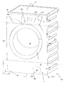
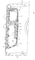
- Figure 1 schematically shows a perspective view of a laundry treatment device 100 according to the present invention.
- the teaching of the present invention may be applied to substantially any appliance for laundry treatment, e.g. to washer/dryers, washing machines (as exemplary illustrated in the figures and to which reference will be made in the following by way of a non-limiting example only), dryers, etc.
- the device 100 comprises a casing 2, preferably substantially parallelepiped-shaped, which encloses an inner compartment comprising a laundry treatment chamber, for example a rotating drum 12 for housing the laundry to be treated and, in the case of a washing machine or a washer/drier, a tub encasing the drum 12 (tub is not visible in the appended drawings).
- the device includes an access door 3 provided on a front wall 4 of the casing for accessing the laundry treatment chamber 12 thereby allowing loading/unloading of the laundry by a user.
- the casing 2 preferably also includes a bottom wall or basement 7, a top wall 6, a back wall (not visible), and two opposite lateral walls (only lateral wall 9 is visible in the drawings).
- lateral walls, front and rear walls, top wall and basement are separated pieces which are then assembled together via suitable fastening means.
- some of these walls can be a single piece, for example lateral walls and back wall can be a single U-shaped piece. Walls are preferably made of metal, however also plastic is possible. Also, in a non-depicted embodiment, some of the walls can be made of a material, and some other(s) can be made of a different material.
- a horizontal plane is defined (plane (XY) in Figure 1 ), which is generally the plane on which the bottom wall or basement 7 lies and generally it is also parallel to the top wall 6 of the casing 2 in a mounted configuration.
- the device 100 also extends along a vertical direction denoted with Z (see Figure 1 ).
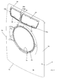
- the front wall 4 of the casing includes an external continuous surface 4a having a plurality of apertures, as better detailed below.
- the front external surface is the external front surface of the device 100.
- Front wall 4 is preferably made of a metallic material, for example in stainless steel.
- the front surface 4a is preferably continuous and even more preferably seamless, at least in the visible portion(s) of the same.
- Continuous surface means that the surface is formed as a single member.
- Sealess means that, in addition to be continuous, there are no seams which indicate that for example welding has been used to join together different parts.
- portions of the front wall 4 can be present. The absence of seams improves the overall appearance of the laundry treatment device 100.
- the front wall 4 preferably includes four rounded corners 4b, 4c, 4d, 4e along its outer edge.
- "Rounded corner” means a corner which does not include sharp and abrupt changes in directions of the surfaces forming the same; on the contrary in a rounded corner the surfaces merges smoothly and with continuity.
- the round corners give a more aesthetically pleasant look to the device 100, and they also make the use of the device safer for the user, which could be injured by sharp corners.
- the front wall 4 can be obtained by a single sheet of metal.
- it can be obtained by a sheet of stainless steel.
- the front wall can be coated by suitable coating to prevent corrosion.
- the front wall can be colored of any color and gloss.
- the front wall 4 defines a top portion 4a', a middle portion 4a"' and a bottom portion 4a", the terms “top”, “middle” and “bottom” used with reference to the standard standing configuration of the laundry treatment device 100 when in use.
- top portion 4a' and the middle portion 4a"' of the front wall 4 are a single (or one-piece) element, i.e., having a continuous and/or seamless front surface 4a, while the bottom portion 4a" can be permanently fixed to it, for example welded to it, or it can even be added as an additional element which can be disassembled from the rest of the front wall.
- the front wall 4 includes an outer edge which can be divided in a top edge 50a, which is the portion of the outer edge comprised between corners 4b and 4c, a bottom edge 50b, which is the portion of the edge located between corners 4d and 4e, and two lateral opposite edges, 50c and 50d which are the portions of outer edge present between corners 4b and 4e, and 4c and 4d, respectively.
- Front surface 4a includes a laundry opening 3a for the access into the laundry treatment device 100, in particular to the laundry treatment chamber 12 so that laundry can be loaded or unloaded to/from the laundry treatment device 100.
- the opening 3a is openable and closable by the door 3, which is advantageously hinged to front wall 4.
- the door 3 is coupled to a recessed portion 3b of the front wall 4a: in this embodiment, the front wall 4 includes the recessed portion (see figures 3 and 4 ) in the center of which the door opening 3a is formed.
- the dimensions of the opening 3a are such to be suitable to accommodate the door 3.
- the door is then rotatably coupled to the door opening and, when mounted and in a closed position, it preferably does not project substantially beyond the front surface 4a due to the recess presence.
- an outer surface of door 3 preferably matches the front surface 4a of front wall 4.
- the door 3 and the recessed portion 3b are located in the middle portion 4a"' of the front wall.
- the front wall 4 is not flat, i.e., it does not lie completely on a single plane. On the contrary, it includes a concavity pointing, in the assembled condition, towards the inside of the casing 2, being convex on the outside.
- the front wall 4 - in a section along a plane parallel to plane YZ- has substantially a smoothed trapezoidal shape, the top 4a', the bottom 4a" and the middle portion 4a"' lying on three different planes which form an angle one with respect to the other(s) and also with the vertical direction Z defined by the casing 2, forming in this way the inward concavity.
- the three planes are preferably connected smoothly and without sharp corners, as clearly visible in figure 3 .
- the front wall can include a substantially constant curvature, the concavity still oriented towards the inside of the cabinet.
- the front wall could be a portion of a cylindrical mantel.
- a first and a second side walls 8a, 9a of the front wall 4 extend from its side edges 50c and 50d and are delimited between corners 4b-4e and 4c-4d, respectively.
- the side walls 8a, 9a are substantially a geometrical continuation of the lateral walls of casing 2.
- side walls 8a, 9a and front wall 4 are formed continuously as one body, i.e., they are not an assembly of different pieces but they are integral one to the others, and more preferably there are no seams of welding separating the front from the side walls.
- Front walls and front walls are thus formed as a single piece and even more preferably the front surface 4a of the front wall is smoothly connected to the front surfaces 8a',9a' of the side walls 8a and 9a, e.g. no sharp curvature changes are present.
- an upper wall 6a and a bottom wall 7a extend from the top and bottom edge, 50a and 50b, respectively, of the front wall.
- upper wall and bottom wall are continuous with the front wall.
- corners 4b, 4c, 4d, 4e formed where side walls and upper/bottom walls merge into the front wall are seamless, because they are not formed by joining different elements, but they are formed during a single process of forming of the front wall, for example by pressing a single metallic sheet.
- the two side walls 8a, 9a extend from the side edges 50c and 50d of the front wall 4 substantially perpendicularly to the front wall 4 towards the lateral walls 9 , so as to be aligned to the latter.
- upper and bottom walls 6a, 7a extend from the top edge 50a and bottom edge 50b substantially perpendicularly to the front wall 4, respectively towards the top and bottom walls 6,7 of the casing, preferably so as to be aligned with the latter.
- At least one of bottom wall 7a and side walls 8a, 9a, more preferably all of them, includes a flange to secure the front wall 4 to the rest of the casing 2.
- At least a flange extends substantially perpendicularly to the side walls 8a, 9a, or bottom wall 7a, respectively, from which it departs.
- Flanges can be formed continuously with the wall from which they extend, or they can be welded to the same. In a different embodiment, only some of the flanges are formed continuously while others are fixed to the front wall 4. These flanges are not visible from the outside of the appliance when the front wall 4 is assembled to the rest of the casing, being hidden inside the casing 2 itself.
- flanges 19a, 19b, 19c include coupling holes, all indicated with 39 in the appended drawings, in order to couple the flanges 19a, 19b, 19c of walls 7,9 to the flanges of the rest of the casing, so that the front wall is coupled to the rest of the casing 2 via suitable fastening elements (not visible) inserted or otherwise coupled to the holes 39.
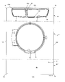
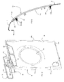
- front wall 4 includes a second aperture 15, called panel aperture.
- the front wall 4 includes also a third aperture, called drawer aperture 60.
- the panel aperture 15 and/or the drawer aperture 60 is (are) located at the top portion 4a' of the front wall.
- the panel aperture 15 and the drawer aperture 60 are each substantially a through hole within the front wall, in other words the panel aperture and/or the drawer aperture is(are) completely surrounded in all directions by the front wall.
- the panel aperture 15 and/or the drawer aperture 60 includes each an outer edge, 15a and 60a, respectively, which defines a closed curve, such as a loop.
- panel aperture 15 and drawer aperture 60 are located one adjacent to the other substantially at the same height along the Z direction on the front wall 4.
- a crosspiece 66 advantageously separates the panel aperture 15 from the drawer aperture 60 (and vice-versa).
- the crosspiece 66 has preferably an elongated shape with two distal opposite ends 66b, 66c. As visible in the figures, preferably the crosspiece 66 has an elongated shape and has a longitudinal extension substantially parallel to the vertical axis Z.
- Crosspiece 66 includes a portion of the edge 60a of the drawer aperture 60 and a portion of the edge 15a of the panel aperture 15a, corresponding to its longitudinal opposite edges.
- crosspiece 66 includes a front surface 66a which is oriented towards the outside of the casing 2.
- the front surface 66a of the crosspiece 66 and the front surface 4a of the front wall 4 are a continuous uniform surface, and even more preferably this continuous uniform surface is also seamless.
- the crosspiece 66 is substantially an integral part of the front wall 4: in the front wall 4 there are two apertures , the drawer and panel aperture, and the crosspiece is the "remaining" portion of front wall (for example during a punching procedure of a metal sheet for obtaining the apertures) between the two.
- the crosspiece 66 is attached, for example by means of its opposite longitudinal ends 66b, 66c, to the front wall separating the two apertures 60, 15.
- the crosspiece is not an integral piece to the front wall, but a separated element which is then fixed to the front wall 4.
- drawer aperture and panel aperture might be the same aperture, e.g. a single "bigger" aperture can be obtained on the front wall, having the function of the panel and drawer apertures.
- the front wall may comprise a service aperture 99, (shown only in figure 1 ) preferably covered by a service aperture cover 99a, so that a filter (not visible) of the laundry treatment device 100 might be easily accessible.
- the service aperture 99 is provided at the bottom portion 4a" of the front wall 4.a
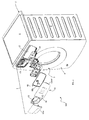
- Laundry treatment device 100 further includes a panel control assembly 1.
- the control panel assembly 1 includes an outer dashboard 11, which in the depicted embodiment spans for most of the width of the front surface 4a of the appliance.
- the dashboard is substantially a basin-shaped rigid shell.
- dashboard 11 is structured for being coupled to the outer front wall 4 of the appliance.
- the dashboard 11 is made of plastic material.
- the dashboard 11 is preferably configured for allowing the user to manually control operation of the appliance and ascertain an operational state thereof.
- the dashboard includes a portion 11ext, external to the casing 2 when laundry treatment device 100 is in the assembled condition (as shown in figure 1 ), which is the portion of the dashboard 11 visible and operable by the user.
- the dashboard external portion 11ext is an exposed part of the control panel assembly also when the device 100 is fully assembled.
- the dashboard external portion 11ext advantageously includes a plurality of apertures and/or input areas 38 through which manually-operable control members 38a are visible or operable.
- the dashboard external portion 11ext For example, received within, or in registry with, the various apertures 38 formed in the dashboard external portion 11ext, there are a main push button used as a main power control, a plurality of operation push-buttons, control knobs and illumination elements.
- the dashboard external portion 11ext might include also a display screen and one or more control knobs.
- the control knob might be rotatable in order to permit the user to select operation cycle settings and other control parameters, with reference to selections indicated by words, icons or other indicia that may be arranged, in printed form or otherwise, on the dashboard.
- Apertures 38 in the dashboard can also render visible illumination of elements (also called light indicators) to provide a visual indication of a particular operation selection corresponding to a knob or push button position.
- illumination of elements may indicate the current operation state in the case of a progressive wash/dry operation comprising multiple sequential cycles or stages.
- the dashboard advantageously includes several arrays of apertures for different light indicators.
- the light visible within the aperture could be either present or absent, in an on/off manner, or follow a determined pattern, e.g. blinking, can have different intensity, or can change color.
- the light coming from different apertures can also have different intensity or color one from the other(s).
- Push buttons, display and apertures to visualize light indicators are known in the art and will not be further detailed below.
- Outer dashboard 11 also includes a rear surface 11r facing the internal of the casing 2, when device 100 is in an assembled configuration. In the latter configuration, the rear surface 11r is located in front of the panel aperture 15 substantially covering (or overlapping) the same. Rear surface 11r is preferably substantially flat.
- control panel assembly 1 also includes a printed circuit board (PCB) 14 for electrically connecting, on a corresponding active surface thereof, the rotatable knobs, the buttons, the display, etc., mentioned with reference to the dashboard.
- PCB printed circuit board
- the PCB electrically connects functional components, e.g. electronic circuitry components (not visible in the figures), for implementing corresponding control functionalities of the control panel assembly.
- functionalities can be one or more of powering, driving, activation, deactivation of one or more operative load including electric, electronic, electro-mechanical and/or electro-hydraulic parts of the appliance, such as motor(s), solenoid valve(s), further PCB, all not shown.
- PCB 14 is connected to the rear surface 11r once the control panel assembly is in an assembled configuration, and when the control panel assembly is mounted on casing 2, it is located internally to the casing 2.
- Control panel assembly 1 is coupled to the front wall 4 at the panel aperture 15.
- the PCB 14 and other possible elements are inserted into the aperture 15.
- the outer dashboard 11 is then fastened onto the front wall 4.
- the external portion 11ext preferably remains outside the casing 2, for example abutting against the front surface 4a and/or onto a surface 18 in proximity of the edge 15a of the aperture 15.
- the appliance 100 further includes a sealing element 40 interposed between the outer dashboard 11 and the abutment surface 18 (see figure 11 ) at the edge 15a of the panel aperture 15.
- the sealing element 40 preferably includes a gasket.
- the sealing element 40 is preferably formed as a strip element and even more preferably it has an annular shape.
- it is made of an elastic material, so that, under stress, it can undergo a certain amount of elastic deformation.
- the sealing element 40 includes at least a boss 41, more preferably a plurality of bosses, located around its perimeter.
- a boss 41 Correspondingly to the boss (or bosses 41), on the abutment surface 18, e.g. on the portion 18a, a notch (or notches) (not illustrated) is(are) formed, in order to house the boss(es) 41.
- the design, form and shape of the boss and the notch allow a good positioning of the sealing element on the ridge, facilitating installation in the correct position.
- the boss/notch coupling also prevents the sealing element to be misplaced during the appliance functioning, which could be caused by vibrations of the appliance.
- the outer dashboard 11 and the front surface 4a are pressed together, so that a portion of the rear surface of the external portion 11ext of the outer dashboard and the abutment surface 18 are in turn deforming the sealing element 40 interposed therebetween. Due to the pressure and deformation, the sealing element 40 fills any possible gap present between the rear surface of the external portion 11ext of dashboard and the abutment surface 18 achieving a sealing function.
- a ridge 19 extends: when the control panel assembly 1 is in an assembled configuration on the casing 2, the sealing element 40 is mounted on the ridge 19.
- the ridge 19 is located substantially in proximity of an edge 11ed of the rear surface 11r of the outer dashboard and it follows the same creating an annular ridge, e.g. it forms a closed-loop on the rear surface 11r of the dashboard 11.
- ridge 19 defines two opposite surfaces 19e, 19f, both substantially perpendicular to the rear surface 11r, on one of which, surface 19e, the sealing element 40 abuts.
- Surface 19f is an inner surface of the ridge 19, e.g. it is the surface that faces itself being in the inside of the loop, while surface 19e is the external surface of the loop.
- the dimensions of the loop formed by the sealing element 40 are slight smaller than the dimensions of the loop formed by ridge 19, so that the sealing element 40 is mounted with interference on the ridge 19 and the risk of accidental unwanted removals is minimized.
- sealing element 40 is a separated element from ridge 19 and it has to be assembled on the latter when the panel control assembly 1 is to be mounted on the casing 2.
- the sealing element 40 can be over-molded on the surface 19e of the ridge 19, so that fewer elements have to be assembled.
- a flange 16 extends.
- the flange 16 includes the abutments surface 18.
- Flange 16 has substantially an L-shape, with a first portion 18a substantially parallel to the external surface 19e of the ridge 19, and a second portion 18b substantially parallel to the rear surface 11r, when the laundry treatment device is in an assembled configuration.
- the flange 16 and the ridge 19 are so dimensioned that, in an assembled configuration, the sealing element 40 is sandwiched and compressed between the external surface 19e of the ridge 19 and the first portion 18a of abutment surface 18.
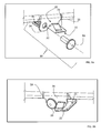
- mechanical coupling device of the first and the second type 20, 30 are preferably used.
- sealing element 40 is not shown (anyway it can be provided or not), for clarity purposes to better visualize the mechanical coupling devices now described.
- the mechanical coupling device of the first and second type 20, 30 couples the outer dashboard 11 to flange 16 extending from the edge 15a of panel aperture 15.
- the mechanical device of the first type 20 is an automatic coupling device that simply requires pressure on the dashboard when the latter is positioned in front of the aperture 15. It includes one or more snap-on connecting member 21, such as snap-on tongues 22 provided on the dashboard 11, which are - in an assembled configuration of the laundry treatment machine - clipping on flange 16 formed around the edge 15a of said panel aperture 15.
- tongues 22 protrude from the inner surface 19f of the ridge 19 and hook the flange 16 in a plurality of different positions around the end 15a of aperture 15, in an assembled configuration.
- ridge 19 is inserted inside aperture 15, it is located internally to flange 16 and a simple application of pressure on dashboard 11 couples the outer dashboard 11 to the front wall 4 due to the fact that tongues 22, which are inwardly elastically bended during the insertion, as soon as they reach the free space behind flange 16, snap on the latter, thereby locking the dashboard onto the front wall 4 in its correct position.
- the device 100 includes the mechanical coupling device of the second type 30, which preferably is activated, e.g. it is used to fasten the dashboard onto the front wall, after the coupling is already obtained by the mechanical coupling device of the first type 20.
- the device of the second type 30 includes preferably a screw element, such as, in the depicted embodiment, screw threads 31 provided in the rear surface 11r of the dashboard 11, a hole 32 provided in the flange 16 formed around the panel aperture 15, and a screw 33 which is inserted in the hole and screwed in the threads to tighten the already obtained coupling.
- a device 30 is provided, and even more preferably a plurality of devices of the second type are arranged in proximity of the outer edge 11ed of the rear surface 11a of dashboard 11, so that a strong and firm "double" coupling is present along the whole edge 11ed of the dashboard 11.
- the screw threads 31 are obtained in a bushing protruding substantially in a perpendicular manner from rear surface 11r.
- Bushing 31 (bushing and screw threads have the same reference number in the drawings) is preferably located within the loop formed by ridge 19.
- bushing is integral with the dashboard.
- the number of bushings is equal to the number of mechanical coupling devices of the second type 30.
- Flange 16 further preferably includes one or more flaps 34 protruding from the same, and advantageously they extends from its second L portion 18b parallel to the rear surface 11r.
- the number of flaps 34 is preferably equal to the number of devices of the second type, so that each flap 34 is perforated by the hole 32 in which screw 33 is inserted and then screwed into bushing 31.
- the outer dashboard 11 is preferably fastened to the crosspiece 66 via a first mechanical coupling system 67.
- the crosspiece 66 advantageously comprises at least an element, part or portion of such first mechanical coupling system.
- the crosspiece includes a hole 64 of the first mechanical coupling system 67, on which a screw 69 is inserted and fastened into a screw thread 68 provided on the rear surface 11a of the outer dashboard 11. More preferably, two holes 64, preferably one on top of the other in the vertical direction Z, are provided also on the crosspiece 66, on which two screws are inserted, which are then screwed into two screw threads formed on the rear surface 11r of the outer dashboard.
- the external portion 11ext of the dashboard 11 is flush-mounted on the front wall 4, being flush with the front surface 4a.
- the aesthetical appearance of the assembled dashboard 11 on the front wall 4 is that of a substantially continuous surface where the external portion 11ext matches the external surface 4a of front wall 4.
- laundry treatment device 100 also includes a detergent drawer 63.
- Detergent drawer 63 is retractably mounted to said front wall 4 so that it can be opened and closed.
- the detergent drawer is generally used to introduce detergents or other products in order to perform a proper washing cycle.
- Detergent drawer includes a detergent drawer front wall 63a, which also remains external to the casing 2 when the laundry treatment device is in an assembled configuration, and it is so shaped to be easily gripped by the user in order to open and/or close the drawer 63.
- Drawer 63 is coupled to drawer aperture 60 of front wall 4.
- a drawer seat 61 is provided, whose dimensions are optimal to house the drawer 63 in a slidable manner.
- the drawer seat 61 is thus fixed to the front wall 4 at the drawer aperture 60.
- Drawer seat 61 is preferably made of plastic material.
- Drawer seat 61 after being mounted on the drawer aperture 60, is then covered by the drawer front wall 63a so that drawer seat becomes substantially invisible when the laundry treatment device 100 is in an assembled configuration.
- Drawer front wall 63a thus is positioned in front of the drawer aperture 60 closing the same.
- the front wall 63a of the drawer is mounted on the drawer seat so that it is substantially flush-mounted on the front wall, i.e., the front surface 4a of the front wall is substantially flush with a front surface of the drawer front wall 63a.
- a single "larger" aperture is provided, as mentioned previously, to house both the control panel assembly 1 and, adjacent to the latter, the detergent drawer 63 (so the crosspiece is not present).
- Drawer seat 61 is inserted into drawer aperture 60 and then fixed to the same.
- a mechanical coupling 65 is used.
- Mechanical coupling 65 includes for example a screw 65a inserted into a hole provided in proximity of the edge 60a of the drawer aperture 60. The screw 65a is thus screwed into a screw thread (not shown) of the drawer seat 61. Any other mechanical coupling can be used as well, in order to firmly fasten the drawer seat to the drawer aperture 60, preferably in proximity of the drawer aperture edge 60a.
- drawer seat 61 and the external portion 11ext of the outer dashboard 11 form an integral piece. Therefore, mechanical system 67 also fastens the drawer seat to the crosspiece automatically means.
- the external portion 11ext of the dashboard 11 and drawer seat 61 are molded together and are made of plastic material.
Landscapes
- Engineering & Computer Science (AREA)
- Textile Engineering (AREA)
- Detail Structures Of Washing Machines And Dryers (AREA)
- Main Body Construction Of Washing Machines And Laundry Dryers (AREA)
Priority Applications (3)
| Application Number | Priority Date | Filing Date | Title |
|---|---|---|---|
| EP13180218.3A EP2837726B1 (de) | 2013-08-13 | 2013-08-13 | Wäschebehandlungsvorrichtung mit einer Steuertafelanordnung |
| PL13180218T PL2837726T3 (pl) | 2013-08-13 | 2013-08-13 | Urządzenie do obróbki pralniczej mające zespół panelu sterującego |
| PCT/EP2014/066239 WO2015022180A1 (en) | 2013-08-13 | 2014-07-29 | A laundry treatment device having a control panel assembly |
Applications Claiming Priority (1)
| Application Number | Priority Date | Filing Date | Title |
|---|---|---|---|
| EP13180218.3A EP2837726B1 (de) | 2013-08-13 | 2013-08-13 | Wäschebehandlungsvorrichtung mit einer Steuertafelanordnung |
Publications (2)
| Publication Number | Publication Date |
|---|---|
| EP2837726A1 true EP2837726A1 (de) | 2015-02-18 |
| EP2837726B1 EP2837726B1 (de) | 2016-10-12 |
Family
ID=48979625
Family Applications (1)
| Application Number | Title | Priority Date | Filing Date |
|---|---|---|---|
| EP13180218.3A Active EP2837726B1 (de) | 2013-08-13 | 2013-08-13 | Wäschebehandlungsvorrichtung mit einer Steuertafelanordnung |
Country Status (3)
| Country | Link |
|---|---|
| EP (1) | EP2837726B1 (de) |
| PL (1) | PL2837726T3 (de) |
| WO (1) | WO2015022180A1 (de) |
Cited By (12)
| Publication number | Priority date | Publication date | Assignee | Title |
|---|---|---|---|---|
| EP3064635A1 (de) * | 2015-03-02 | 2016-09-07 | Electrolux Appliances Aktiebolag | Frontplatte einer Schublade einer Wäschebehandlungsvorrichtung |
| WO2017020961A1 (en) * | 2015-08-06 | 2017-02-09 | Arcelik Anonim Sirketi | Display assembly for household appliance |
| EP3187648A1 (de) * | 2015-12-29 | 2017-07-05 | Electrolux Appliances Aktiebolag | Haushaltsgerät |
| WO2018077057A1 (zh) * | 2016-10-27 | 2018-05-03 | 青岛海尔洗衣机有限公司 | 控制面板结构和家电设备 |
| CN108221297A (zh) * | 2018-03-02 | 2018-06-29 | 青岛海尔滚筒洗衣机有限公司 | 一种箱体结构及洗衣机 |
| US10060066B2 (en) | 2016-06-30 | 2018-08-28 | Whirlpool Corporation | Laundry appliance door assembly |
| WO2019219069A1 (zh) * | 2018-05-18 | 2019-11-21 | 青岛海尔滚筒洗衣机有限公司 | 一种滚筒洗衣机 |
| CN110499607A (zh) * | 2018-05-18 | 2019-11-26 | 青岛海尔滚筒洗衣机有限公司 | 一种滚筒洗衣机 |
| CN110499629A (zh) * | 2018-05-18 | 2019-11-26 | 青岛海尔滚筒洗衣机有限公司 | 一种滚筒洗衣机 |
| CN110499627A (zh) * | 2018-05-18 | 2019-11-26 | 青岛海尔滚筒洗衣机有限公司 | 一种滚筒洗衣机 |
| US10815603B2 (en) | 2016-06-30 | 2020-10-27 | Whirlpool Corporation | Appliance having a touch film on a compound curved surface |
| EP3187647B1 (de) * | 2015-12-29 | 2022-02-23 | Electrolux Appliances Aktiebolag | Haushaltsgerät mit elektronischer platine und verfahren zur herstellung eines haushaltsgeräts |
Families Citing this family (7)
| Publication number | Priority date | Publication date | Assignee | Title |
|---|---|---|---|---|
| US11118295B2 (en) | 2017-11-16 | 2021-09-14 | Whirlpool Corporation | Laundry treating appliance having a user interface within a door assembly |
| CN111764106B (zh) * | 2019-03-12 | 2025-08-26 | 青岛海尔洗涤电器有限公司 | 一种洗衣机 |
| CN111676677A (zh) * | 2020-05-25 | 2020-09-18 | 青岛海尔洗涤电器有限公司 | 一种干衣机 |
| CN113930943B (zh) * | 2020-07-14 | 2023-10-31 | 重庆海尔滚筒洗衣机有限公司 | 一种洗衣机的主控板模块 |
| EP4202102A4 (de) | 2021-03-04 | 2024-03-13 | Samsung Electronics Co., Ltd. | Waschmaschine und wäschepflegevorrichtung |
| JP7616933B2 (ja) * | 2021-04-06 | 2025-01-17 | シャープ株式会社 | 洗濯機 |
| KR102716904B1 (ko) | 2021-06-28 | 2024-10-16 | 엘지전자 주식회사 | 의류처리장치 |
Citations (6)
| Publication number | Priority date | Publication date | Assignee | Title |
|---|---|---|---|---|
| GB1554725A (en) * | 1976-10-11 | 1979-10-31 | Hotpoint Ltd | Airflow arrangements for tumble drying machines |
| US5464955A (en) * | 1993-04-15 | 1995-11-07 | Emerson Electric Co. | Backlit appliance control console |
| DE19651821A1 (de) * | 1996-12-13 | 1998-06-18 | Miele & Cie | Wäschebehandlungs- oder Geschirrspülmaschine |
| EP2140058A2 (de) | 2007-03-06 | 2010-01-06 | LG Electronics Inc. | Wäschebehandlungsvorrichtung |
| EP2339063A2 (de) * | 2009-12-28 | 2011-06-29 | Panasonic Corporation | Trockner |
| WO2012062894A2 (en) * | 2010-11-12 | 2012-05-18 | Arcelik Anonim Sirketi | A dryer comprising a removable piece |
-
2013
- 2013-08-13 EP EP13180218.3A patent/EP2837726B1/de active Active
- 2013-08-13 PL PL13180218T patent/PL2837726T3/pl unknown
-
2014
- 2014-07-29 WO PCT/EP2014/066239 patent/WO2015022180A1/en not_active Ceased
Patent Citations (7)
| Publication number | Priority date | Publication date | Assignee | Title |
|---|---|---|---|---|
| GB1554725A (en) * | 1976-10-11 | 1979-10-31 | Hotpoint Ltd | Airflow arrangements for tumble drying machines |
| US5464955A (en) * | 1993-04-15 | 1995-11-07 | Emerson Electric Co. | Backlit appliance control console |
| DE19651821A1 (de) * | 1996-12-13 | 1998-06-18 | Miele & Cie | Wäschebehandlungs- oder Geschirrspülmaschine |
| EP2140058A2 (de) | 2007-03-06 | 2010-01-06 | LG Electronics Inc. | Wäschebehandlungsvorrichtung |
| EP2140058B1 (de) * | 2007-03-06 | 2013-02-27 | LG Electronics Inc. | Wäschebehandlungsvorrichtung |
| EP2339063A2 (de) * | 2009-12-28 | 2011-06-29 | Panasonic Corporation | Trockner |
| WO2012062894A2 (en) * | 2010-11-12 | 2012-05-18 | Arcelik Anonim Sirketi | A dryer comprising a removable piece |
Cited By (17)
| Publication number | Priority date | Publication date | Assignee | Title |
|---|---|---|---|---|
| WO2016139035A1 (en) * | 2015-03-02 | 2016-09-09 | Electrolux Appliances Aktiebolag | Laundry treatment appliance |
| EP3064635A1 (de) * | 2015-03-02 | 2016-09-07 | Electrolux Appliances Aktiebolag | Frontplatte einer Schublade einer Wäschebehandlungsvorrichtung |
| WO2017020961A1 (en) * | 2015-08-06 | 2017-02-09 | Arcelik Anonim Sirketi | Display assembly for household appliance |
| EP3187648A1 (de) * | 2015-12-29 | 2017-07-05 | Electrolux Appliances Aktiebolag | Haushaltsgerät |
| US9988755B2 (en) | 2015-12-29 | 2018-06-05 | Electrolux Appliances Aktiebolag | Household appliance |
| EP3187647B1 (de) * | 2015-12-29 | 2022-02-23 | Electrolux Appliances Aktiebolag | Haushaltsgerät mit elektronischer platine und verfahren zur herstellung eines haushaltsgeräts |
| US10815603B2 (en) | 2016-06-30 | 2020-10-27 | Whirlpool Corporation | Appliance having a touch film on a compound curved surface |
| US11920285B2 (en) | 2016-06-30 | 2024-03-05 | Whirlpool Corporation | Laundry treating appliance door assembly |
| US10060066B2 (en) | 2016-06-30 | 2018-08-28 | Whirlpool Corporation | Laundry appliance door assembly |
| US10253441B2 (en) | 2016-06-30 | 2019-04-09 | Whirlpool Corporation | Laundry appliance door assembly |
| US11466396B2 (en) | 2016-06-30 | 2022-10-11 | Whirlpool Corporation | Laundry treating appliance door assembly |
| WO2018077057A1 (zh) * | 2016-10-27 | 2018-05-03 | 青岛海尔洗衣机有限公司 | 控制面板结构和家电设备 |
| CN108221297A (zh) * | 2018-03-02 | 2018-06-29 | 青岛海尔滚筒洗衣机有限公司 | 一种箱体结构及洗衣机 |
| CN110499627A (zh) * | 2018-05-18 | 2019-11-26 | 青岛海尔滚筒洗衣机有限公司 | 一种滚筒洗衣机 |
| CN110499629A (zh) * | 2018-05-18 | 2019-11-26 | 青岛海尔滚筒洗衣机有限公司 | 一种滚筒洗衣机 |
| CN110499607A (zh) * | 2018-05-18 | 2019-11-26 | 青岛海尔滚筒洗衣机有限公司 | 一种滚筒洗衣机 |
| WO2019219069A1 (zh) * | 2018-05-18 | 2019-11-21 | 青岛海尔滚筒洗衣机有限公司 | 一种滚筒洗衣机 |
Also Published As
| Publication number | Publication date |
|---|---|
| WO2015022180A1 (en) | 2015-02-19 |
| PL2837726T3 (pl) | 2017-06-30 |
| EP2837726B1 (de) | 2016-10-12 |
Similar Documents
| Publication | Publication Date | Title |
|---|---|---|
| EP2837726B1 (de) | Wäschebehandlungsvorrichtung mit einer Steuertafelanordnung | |
| US9677213B2 (en) | Laundry treatment device having a control panel assembly | |
| US9803309B2 (en) | Laundry treatment device having a control panel assembly | |
| EP2837728A1 (de) | Wäschebehandlungsvorrichtung mit einer Steuertafelanordnung | |
| US8690268B2 (en) | Laundry treating apparatus | |
| CN108532234B (zh) | 衣物处理装置用门体组件和衣物处理装置 | |
| EP2837733B1 (de) | Wäschebehandlungsvorrichtung mit einer Steuertafelanordnung | |
| EP2837725A1 (de) | Wäschebehandlungsvorrichtung mit einer Steuertafelanordnung | |
| CA2527758C (en) | Appliance with membrane overlay | |
| WO2015028245A1 (en) | Door assembly for a laundry treatment device | |
| KR200395273Y1 (ko) | 세탁기의 전면부 구조 | |
| KR101706969B1 (ko) | 의류처리장치 및 도어 | |
| JP2021029724A (ja) | 洗濯機 | |
| EP4692442A1 (de) | Vorrichtung zur behandlung von kleidung | |
| KR20130026355A (ko) | 세탁기 | |
| KR101227478B1 (ko) | 세탁 장치 | |
| US20070193309A1 (en) | Washing machine | |
| KR101306692B1 (ko) | 세탁 장치 | |
| AU2024351523A1 (en) | Clothing treatment apparatus | |
| KR20160084326A (ko) | 의류처리장치 및 도어 | |
| KR20070040938A (ko) | 세탁 장치 |
Legal Events
| Date | Code | Title | Description |
|---|---|---|---|
| 17P | Request for examination filed |
Effective date: 20130813 |
|
| AK | Designated contracting states |
Kind code of ref document: A1 Designated state(s): AL AT BE BG CH CY CZ DE DK EE ES FI FR GB GR HR HU IE IS IT LI LT LU LV MC MK MT NL NO PL PT RO RS SE SI SK SM TR |
|
| AX | Request for extension of the european patent |
Extension state: BA ME |
|
| PUAI | Public reference made under article 153(3) epc to a published international application that has entered the european phase |
Free format text: ORIGINAL CODE: 0009012 |
|
| R17P | Request for examination filed (corrected) |
Effective date: 20150818 |
|
| RBV | Designated contracting states (corrected) |
Designated state(s): AL AT BE BG CH CY CZ DE DK EE ES FI FR GB GR HR HU IE IS IT LI LT LU LV MC MK MT NL NO PL PT RO RS SE SI SK SM TR |
|
| 17Q | First examination report despatched |
Effective date: 20151204 |
|
| GRAP | Despatch of communication of intention to grant a patent |
Free format text: ORIGINAL CODE: EPIDOSNIGR1 |
|
| INTG | Intention to grant announced |
Effective date: 20160621 |
|
| GRAS | Grant fee paid |
Free format text: ORIGINAL CODE: EPIDOSNIGR3 |
|
| GRAA | (expected) grant |
Free format text: ORIGINAL CODE: 0009210 |
|
| AK | Designated contracting states |
Kind code of ref document: B1 Designated state(s): AL AT BE BG CH CY CZ DE DK EE ES FI FR GB GR HR HU IE IS IT LI LT LU LV MC MK MT NL NO PL PT RO RS SE SI SK SM TR |
|
| REG | Reference to a national code |
Ref country code: GB Ref legal event code: FG4D |
|
| REG | Reference to a national code |
Ref country code: CH Ref legal event code: EP |
|
| REG | Reference to a national code |
Ref country code: AT Ref legal event code: REF Ref document number: 836607 Country of ref document: AT Kind code of ref document: T Effective date: 20161015 |
|
| REG | Reference to a national code |
Ref country code: IE Ref legal event code: FG4D |
|
| REG | Reference to a national code |
Ref country code: DE Ref legal event code: R096 Ref document number: 602013012654 Country of ref document: DE |
|
| REG | Reference to a national code |
Ref country code: LT Ref legal event code: MG4D |
|
| REG | Reference to a national code |
Ref country code: NL Ref legal event code: MP Effective date: 20161012 |
|
| PG25 | Lapsed in a contracting state [announced via postgrant information from national office to epo] |
Ref country code: LV Free format text: LAPSE BECAUSE OF FAILURE TO SUBMIT A TRANSLATION OF THE DESCRIPTION OR TO PAY THE FEE WITHIN THE PRESCRIBED TIME-LIMIT Effective date: 20161012 |
|
| REG | Reference to a national code |
Ref country code: AT Ref legal event code: MK05 Ref document number: 836607 Country of ref document: AT Kind code of ref document: T Effective date: 20161012 |
|
| PG25 | Lapsed in a contracting state [announced via postgrant information from national office to epo] |
Ref country code: NO Free format text: LAPSE BECAUSE OF FAILURE TO SUBMIT A TRANSLATION OF THE DESCRIPTION OR TO PAY THE FEE WITHIN THE PRESCRIBED TIME-LIMIT Effective date: 20170112 Ref country code: SE Free format text: LAPSE BECAUSE OF FAILURE TO SUBMIT A TRANSLATION OF THE DESCRIPTION OR TO PAY THE FEE WITHIN THE PRESCRIBED TIME-LIMIT Effective date: 20161012 Ref country code: GR Free format text: LAPSE BECAUSE OF FAILURE TO SUBMIT A TRANSLATION OF THE DESCRIPTION OR TO PAY THE FEE WITHIN THE PRESCRIBED TIME-LIMIT Effective date: 20170113 Ref country code: LT Free format text: LAPSE BECAUSE OF FAILURE TO SUBMIT A TRANSLATION OF THE DESCRIPTION OR TO PAY THE FEE WITHIN THE PRESCRIBED TIME-LIMIT Effective date: 20161012 |
|
| PG25 | Lapsed in a contracting state [announced via postgrant information from national office to epo] |
Ref country code: NL Free format text: LAPSE BECAUSE OF FAILURE TO SUBMIT A TRANSLATION OF THE DESCRIPTION OR TO PAY THE FEE WITHIN THE PRESCRIBED TIME-LIMIT Effective date: 20161012 Ref country code: AT Free format text: LAPSE BECAUSE OF FAILURE TO SUBMIT A TRANSLATION OF THE DESCRIPTION OR TO PAY THE FEE WITHIN THE PRESCRIBED TIME-LIMIT Effective date: 20161012 Ref country code: BE Free format text: LAPSE BECAUSE OF FAILURE TO SUBMIT A TRANSLATION OF THE DESCRIPTION OR TO PAY THE FEE WITHIN THE PRESCRIBED TIME-LIMIT Effective date: 20161012 Ref country code: RS Free format text: LAPSE BECAUSE OF FAILURE TO SUBMIT A TRANSLATION OF THE DESCRIPTION OR TO PAY THE FEE WITHIN THE PRESCRIBED TIME-LIMIT Effective date: 20161012 Ref country code: FI Free format text: LAPSE BECAUSE OF FAILURE TO SUBMIT A TRANSLATION OF THE DESCRIPTION OR TO PAY THE FEE WITHIN THE PRESCRIBED TIME-LIMIT Effective date: 20161012 Ref country code: IS Free format text: LAPSE BECAUSE OF FAILURE TO SUBMIT A TRANSLATION OF THE DESCRIPTION OR TO PAY THE FEE WITHIN THE PRESCRIBED TIME-LIMIT Effective date: 20170212 Ref country code: PT Free format text: LAPSE BECAUSE OF FAILURE TO SUBMIT A TRANSLATION OF THE DESCRIPTION OR TO PAY THE FEE WITHIN THE PRESCRIBED TIME-LIMIT Effective date: 20170213 Ref country code: ES Free format text: LAPSE BECAUSE OF FAILURE TO SUBMIT A TRANSLATION OF THE DESCRIPTION OR TO PAY THE FEE WITHIN THE PRESCRIBED TIME-LIMIT Effective date: 20161012 Ref country code: HR Free format text: LAPSE BECAUSE OF FAILURE TO SUBMIT A TRANSLATION OF THE DESCRIPTION OR TO PAY THE FEE WITHIN THE PRESCRIBED TIME-LIMIT Effective date: 20161012 |
|
| REG | Reference to a national code |
Ref country code: DE Ref legal event code: R097 Ref document number: 602013012654 Country of ref document: DE |
|
| PG25 | Lapsed in a contracting state [announced via postgrant information from national office to epo] |
Ref country code: SK Free format text: LAPSE BECAUSE OF FAILURE TO SUBMIT A TRANSLATION OF THE DESCRIPTION OR TO PAY THE FEE WITHIN THE PRESCRIBED TIME-LIMIT Effective date: 20161012 Ref country code: EE Free format text: LAPSE BECAUSE OF FAILURE TO SUBMIT A TRANSLATION OF THE DESCRIPTION OR TO PAY THE FEE WITHIN THE PRESCRIBED TIME-LIMIT Effective date: 20161012 Ref country code: RO Free format text: LAPSE BECAUSE OF FAILURE TO SUBMIT A TRANSLATION OF THE DESCRIPTION OR TO PAY THE FEE WITHIN THE PRESCRIBED TIME-LIMIT Effective date: 20161012 Ref country code: CZ Free format text: LAPSE BECAUSE OF FAILURE TO SUBMIT A TRANSLATION OF THE DESCRIPTION OR TO PAY THE FEE WITHIN THE PRESCRIBED TIME-LIMIT Effective date: 20161012 Ref country code: DK Free format text: LAPSE BECAUSE OF FAILURE TO SUBMIT A TRANSLATION OF THE DESCRIPTION OR TO PAY THE FEE WITHIN THE PRESCRIBED TIME-LIMIT Effective date: 20161012 |
|
| PLBE | No opposition filed within time limit |
Free format text: ORIGINAL CODE: 0009261 |
|
| STAA | Information on the status of an ep patent application or granted ep patent |
Free format text: STATUS: NO OPPOSITION FILED WITHIN TIME LIMIT |
|
| PG25 | Lapsed in a contracting state [announced via postgrant information from national office to epo] |
Ref country code: SM Free format text: LAPSE BECAUSE OF FAILURE TO SUBMIT A TRANSLATION OF THE DESCRIPTION OR TO PAY THE FEE WITHIN THE PRESCRIBED TIME-LIMIT Effective date: 20161012 Ref country code: BG Free format text: LAPSE BECAUSE OF FAILURE TO SUBMIT A TRANSLATION OF THE DESCRIPTION OR TO PAY THE FEE WITHIN THE PRESCRIBED TIME-LIMIT Effective date: 20170112 |
|
| 26N | No opposition filed |
Effective date: 20170713 |
|
| PG25 | Lapsed in a contracting state [announced via postgrant information from national office to epo] |
Ref country code: SI Free format text: LAPSE BECAUSE OF FAILURE TO SUBMIT A TRANSLATION OF THE DESCRIPTION OR TO PAY THE FEE WITHIN THE PRESCRIBED TIME-LIMIT Effective date: 20161012 |
|
| REG | Reference to a national code |
Ref country code: CH Ref legal event code: PL |
|
| PG25 | Lapsed in a contracting state [announced via postgrant information from national office to epo] |
Ref country code: MC Free format text: LAPSE BECAUSE OF FAILURE TO SUBMIT A TRANSLATION OF THE DESCRIPTION OR TO PAY THE FEE WITHIN THE PRESCRIBED TIME-LIMIT Effective date: 20161012 |
|
| GBPC | Gb: european patent ceased through non-payment of renewal fee |
Effective date: 20170813 |
|
| PG25 | Lapsed in a contracting state [announced via postgrant information from national office to epo] |
Ref country code: CH Free format text: LAPSE BECAUSE OF NON-PAYMENT OF DUE FEES Effective date: 20170831 Ref country code: LI Free format text: LAPSE BECAUSE OF NON-PAYMENT OF DUE FEES Effective date: 20170831 |
|
| REG | Reference to a national code |
Ref country code: FR Ref legal event code: ST Effective date: 20180430 |
|
| REG | Reference to a national code |
Ref country code: IE Ref legal event code: MM4A |
|
| PG25 | Lapsed in a contracting state [announced via postgrant information from national office to epo] |
Ref country code: LU Free format text: LAPSE BECAUSE OF NON-PAYMENT OF DUE FEES Effective date: 20170813 |
|
| PG25 | Lapsed in a contracting state [announced via postgrant information from national office to epo] |
Ref country code: GB Free format text: LAPSE BECAUSE OF NON-PAYMENT OF DUE FEES Effective date: 20170813 Ref country code: IE Free format text: LAPSE BECAUSE OF NON-PAYMENT OF DUE FEES Effective date: 20170813 |
|
| PG25 | Lapsed in a contracting state [announced via postgrant information from national office to epo] |
Ref country code: FR Free format text: LAPSE BECAUSE OF NON-PAYMENT OF DUE FEES Effective date: 20170831 |
|
| PG25 | Lapsed in a contracting state [announced via postgrant information from national office to epo] |
Ref country code: MT Free format text: LAPSE BECAUSE OF NON-PAYMENT OF DUE FEES Effective date: 20170813 |
|
| PG25 | Lapsed in a contracting state [announced via postgrant information from national office to epo] |
Ref country code: HU Free format text: LAPSE BECAUSE OF FAILURE TO SUBMIT A TRANSLATION OF THE DESCRIPTION OR TO PAY THE FEE WITHIN THE PRESCRIBED TIME-LIMIT; INVALID AB INITIO Effective date: 20130813 |
|
| PG25 | Lapsed in a contracting state [announced via postgrant information from national office to epo] |
Ref country code: CY Free format text: LAPSE BECAUSE OF FAILURE TO SUBMIT A TRANSLATION OF THE DESCRIPTION OR TO PAY THE FEE WITHIN THE PRESCRIBED TIME-LIMIT Effective date: 20161012 |
|
| PG25 | Lapsed in a contracting state [announced via postgrant information from national office to epo] |
Ref country code: MK Free format text: LAPSE BECAUSE OF FAILURE TO SUBMIT A TRANSLATION OF THE DESCRIPTION OR TO PAY THE FEE WITHIN THE PRESCRIBED TIME-LIMIT Effective date: 20161012 |
|
| PG25 | Lapsed in a contracting state [announced via postgrant information from national office to epo] |
Ref country code: TR Free format text: LAPSE BECAUSE OF FAILURE TO SUBMIT A TRANSLATION OF THE DESCRIPTION OR TO PAY THE FEE WITHIN THE PRESCRIBED TIME-LIMIT Effective date: 20161012 |
|
| PG25 | Lapsed in a contracting state [announced via postgrant information from national office to epo] |
Ref country code: AL Free format text: LAPSE BECAUSE OF FAILURE TO SUBMIT A TRANSLATION OF THE DESCRIPTION OR TO PAY THE FEE WITHIN THE PRESCRIBED TIME-LIMIT Effective date: 20161012 |
|
| PGFP | Annual fee paid to national office [announced via postgrant information from national office to epo] |
Ref country code: IT Payment date: 20220825 Year of fee payment: 10 |
|
| P01 | Opt-out of the competence of the unified patent court (upc) registered |
Effective date: 20230625 |
|
| PG25 | Lapsed in a contracting state [announced via postgrant information from national office to epo] |
Ref country code: IT Free format text: LAPSE BECAUSE OF NON-PAYMENT OF DUE FEES Effective date: 20230813 |
|
| PGFP | Annual fee paid to national office [announced via postgrant information from national office to epo] |
Ref country code: DE Payment date: 20250827 Year of fee payment: 13 |
|
| PGFP | Annual fee paid to national office [announced via postgrant information from national office to epo] |
Ref country code: PL Payment date: 20250804 Year of fee payment: 13 |