EP2837563A2 - Enhanced motor cooling system and method - Google Patents
Enhanced motor cooling system and method Download PDFInfo
- Publication number
- EP2837563A2 EP2837563A2 EP14174067.0A EP14174067A EP2837563A2 EP 2837563 A2 EP2837563 A2 EP 2837563A2 EP 14174067 A EP14174067 A EP 14174067A EP 2837563 A2 EP2837563 A2 EP 2837563A2
- Authority
- EP
- European Patent Office
- Prior art keywords
- outlet
- diverter
- ram
- inlet
- passage
- Prior art date
- Legal status (The legal status is an assumption and is not a legal conclusion. Google has not performed a legal analysis and makes no representation as to the accuracy of the status listed.)
- Granted
Links
Images

Classifications
-
- F—MECHANICAL ENGINEERING; LIGHTING; HEATING; WEAPONS; BLASTING
- F04—POSITIVE - DISPLACEMENT MACHINES FOR LIQUIDS; PUMPS FOR LIQUIDS OR ELASTIC FLUIDS
- F04F—PUMPING OF FLUID BY DIRECT CONTACT OF ANOTHER FLUID OR BY USING INERTIA OF FLUID TO BE PUMPED; SIPHONS
- F04F5/00—Jet pumps, i.e. devices in which flow is induced by pressure drop caused by velocity of another fluid flow
- F04F5/14—Jet pumps, i.e. devices in which flow is induced by pressure drop caused by velocity of another fluid flow the inducing fluid being elastic fluid
-
- B—PERFORMING OPERATIONS; TRANSPORTING
- B64—AIRCRAFT; AVIATION; COSMONAUTICS
- B64D—EQUIPMENT FOR FITTING IN OR TO AIRCRAFT; FLIGHT SUITS; PARACHUTES; ARRANGEMENTS OR MOUNTING OF POWER PLANTS OR PROPULSION TRANSMISSIONS IN AIRCRAFT
- B64D13/00—Arrangements or adaptations of air-treatment apparatus for aircraft crew or passengers, or freight space, or structural parts of the aircraft
- B64D13/06—Arrangements or adaptations of air-treatment apparatus for aircraft crew or passengers, or freight space, or structural parts of the aircraft the air being conditioned
-
- B—PERFORMING OPERATIONS; TRANSPORTING
- B60—VEHICLES IN GENERAL
- B60K—ARRANGEMENT OR MOUNTING OF PROPULSION UNITS OR OF TRANSMISSIONS IN VEHICLES; ARRANGEMENT OR MOUNTING OF PLURAL DIVERSE PRIME-MOVERS IN VEHICLES; AUXILIARY DRIVES FOR VEHICLES; INSTRUMENTATION OR DASHBOARDS FOR VEHICLES; ARRANGEMENTS IN CONNECTION WITH COOLING, AIR INTAKE, GAS EXHAUST OR FUEL SUPPLY OF PROPULSION UNITS IN VEHICLES
- B60K11/00—Arrangement in connection with cooling of propulsion units
- B60K11/06—Arrangement in connection with cooling of propulsion units with air cooling
-
- F—MECHANICAL ENGINEERING; LIGHTING; HEATING; WEAPONS; BLASTING
- F04—POSITIVE - DISPLACEMENT MACHINES FOR LIQUIDS; PUMPS FOR LIQUIDS OR ELASTIC FLUIDS
- F04F—PUMPING OF FLUID BY DIRECT CONTACT OF ANOTHER FLUID OR BY USING INERTIA OF FLUID TO BE PUMPED; SIPHONS
- F04F5/00—Jet pumps, i.e. devices in which flow is induced by pressure drop caused by velocity of another fluid flow
- F04F5/14—Jet pumps, i.e. devices in which flow is induced by pressure drop caused by velocity of another fluid flow the inducing fluid being elastic fluid
- F04F5/16—Jet pumps, i.e. devices in which flow is induced by pressure drop caused by velocity of another fluid flow the inducing fluid being elastic fluid displacing elastic fluids
- F04F5/18—Jet pumps, i.e. devices in which flow is induced by pressure drop caused by velocity of another fluid flow the inducing fluid being elastic fluid displacing elastic fluids for compressing
-
- F—MECHANICAL ENGINEERING; LIGHTING; HEATING; WEAPONS; BLASTING
- F04—POSITIVE - DISPLACEMENT MACHINES FOR LIQUIDS; PUMPS FOR LIQUIDS OR ELASTIC FLUIDS
- F04F—PUMPING OF FLUID BY DIRECT CONTACT OF ANOTHER FLUID OR BY USING INERTIA OF FLUID TO BE PUMPED; SIPHONS
- F04F7/00—Pumps displacing fluids by using inertia thereof, e.g. by generating vibrations therein
-
- F—MECHANICAL ENGINEERING; LIGHTING; HEATING; WEAPONS; BLASTING
- F16—ENGINEERING ELEMENTS AND UNITS; GENERAL MEASURES FOR PRODUCING AND MAINTAINING EFFECTIVE FUNCTIONING OF MACHINES OR INSTALLATIONS; THERMAL INSULATION IN GENERAL
- F16K—VALVES; TAPS; COCKS; ACTUATING-FLOATS; DEVICES FOR VENTING OR AERATING
- F16K11/00—Multiple-way valves, e.g. mixing valves; Pipe fittings incorporating such valves
- F16K11/02—Multiple-way valves, e.g. mixing valves; Pipe fittings incorporating such valves with all movable sealing faces moving as one unit
- F16K11/04—Multiple-way valves, e.g. mixing valves; Pipe fittings incorporating such valves with all movable sealing faces moving as one unit comprising only lift valves
- F16K11/044—Multiple-way valves, e.g. mixing valves; Pipe fittings incorporating such valves with all movable sealing faces moving as one unit comprising only lift valves with movable valve members positioned between valve seats
-
- F—MECHANICAL ENGINEERING; LIGHTING; HEATING; WEAPONS; BLASTING
- F16—ENGINEERING ELEMENTS AND UNITS; GENERAL MEASURES FOR PRODUCING AND MAINTAINING EFFECTIVE FUNCTIONING OF MACHINES OR INSTALLATIONS; THERMAL INSULATION IN GENERAL
- F16K—VALVES; TAPS; COCKS; ACTUATING-FLOATS; DEVICES FOR VENTING OR AERATING
- F16K11/00—Multiple-way valves, e.g. mixing valves; Pipe fittings incorporating such valves
- F16K11/02—Multiple-way valves, e.g. mixing valves; Pipe fittings incorporating such valves with all movable sealing faces moving as one unit
- F16K11/04—Multiple-way valves, e.g. mixing valves; Pipe fittings incorporating such valves with all movable sealing faces moving as one unit comprising only lift valves
- F16K11/052—Multiple-way valves, e.g. mixing valves; Pipe fittings incorporating such valves with all movable sealing faces moving as one unit comprising only lift valves with pivoted closure members, e.g. butterfly valves
-
- B—PERFORMING OPERATIONS; TRANSPORTING
- B64—AIRCRAFT; AVIATION; COSMONAUTICS
- B64D—EQUIPMENT FOR FITTING IN OR TO AIRCRAFT; FLIGHT SUITS; PARACHUTES; ARRANGEMENTS OR MOUNTING OF POWER PLANTS OR PROPULSION TRANSMISSIONS IN AIRCRAFT
- B64D13/00—Arrangements or adaptations of air-treatment apparatus for aircraft crew or passengers, or freight space, or structural parts of the aircraft
- B64D13/06—Arrangements or adaptations of air-treatment apparatus for aircraft crew or passengers, or freight space, or structural parts of the aircraft the air being conditioned
- B64D2013/0603—Environmental Control Systems
- B64D2013/0644—Environmental Control Systems including electric motors or generators
-
- B—PERFORMING OPERATIONS; TRANSPORTING
- B64—AIRCRAFT; AVIATION; COSMONAUTICS
- B64D—EQUIPMENT FOR FITTING IN OR TO AIRCRAFT; FLIGHT SUITS; PARACHUTES; ARRANGEMENTS OR MOUNTING OF POWER PLANTS OR PROPULSION TRANSMISSIONS IN AIRCRAFT
- B64D13/00—Arrangements or adaptations of air-treatment apparatus for aircraft crew or passengers, or freight space, or structural parts of the aircraft
- B64D13/06—Arrangements or adaptations of air-treatment apparatus for aircraft crew or passengers, or freight space, or structural parts of the aircraft the air being conditioned
- B64D2013/0603—Environmental Control Systems
- B64D2013/0685—Environmental Control Systems with ozone control
-
- F—MECHANICAL ENGINEERING; LIGHTING; HEATING; WEAPONS; BLASTING
- F04—POSITIVE - DISPLACEMENT MACHINES FOR LIQUIDS; PUMPS FOR LIQUIDS OR ELASTIC FLUIDS
- F04F—PUMPING OF FLUID BY DIRECT CONTACT OF ANOTHER FLUID OR BY USING INERTIA OF FLUID TO BE PUMPED; SIPHONS
- F04F5/00—Jet pumps, i.e. devices in which flow is induced by pressure drop caused by velocity of another fluid flow
- F04F5/44—Component parts, details, or accessories not provided for in, or of interest apart from, groups F04F5/02 - F04F5/42
- F04F5/46—Arrangements of nozzles
- F04F5/462—Arrangements of nozzles with provisions for cooling the fluid
-
- Y—GENERAL TAGGING OF NEW TECHNOLOGICAL DEVELOPMENTS; GENERAL TAGGING OF CROSS-SECTIONAL TECHNOLOGIES SPANNING OVER SEVERAL SECTIONS OF THE IPC; TECHNICAL SUBJECTS COVERED BY FORMER USPC CROSS-REFERENCE ART COLLECTIONS [XRACs] AND DIGESTS
- Y02—TECHNOLOGIES OR APPLICATIONS FOR MITIGATION OR ADAPTATION AGAINST CLIMATE CHANGE
- Y02T—CLIMATE CHANGE MITIGATION TECHNOLOGIES RELATED TO TRANSPORTATION
- Y02T50/00—Aeronautics or air transport
- Y02T50/50—On board measures aiming to increase energy efficiency
-
- Y—GENERAL TAGGING OF NEW TECHNOLOGICAL DEVELOPMENTS; GENERAL TAGGING OF CROSS-SECTIONAL TECHNOLOGIES SPANNING OVER SEVERAL SECTIONS OF THE IPC; TECHNICAL SUBJECTS COVERED BY FORMER USPC CROSS-REFERENCE ART COLLECTIONS [XRACs] AND DIGESTS
- Y10—TECHNICAL SUBJECTS COVERED BY FORMER USPC
- Y10T—TECHNICAL SUBJECTS COVERED BY FORMER US CLASSIFICATION
- Y10T137/00—Fluid handling
- Y10T137/8593—Systems
- Y10T137/877—With flow control means for branched passages
- Y10T137/87788—With valve or movable deflector at junction
- Y10T137/87812—Pivoted valve or deflector
Definitions
- the subject matter disclosed herein relates generally to aircraft environmental control and, more particularly, to systems and methods for enhanced motor cooling of a motor in a cabin air compressor.
- a cabin air conditioner in an ECS may be utilized to condition aircraft cabin air.
- the cabin air conditioner typically has one or more Cabin Air Compressors (CAC's) which compresses ram air entering the CAC from a ram air system before being delivered to the cabin air conditioner.
- CAC's Cabin Air Compressors
- the cabin air conditioner processes this compressed air from the CAC and brings it to a desired temperature for delivery to an aircraft cabin.
- the CAC's are typically driven by air-cooled electric motors that are cooled by a flow of cooling air typically drawn by the ram air system.
- the flow of cooling air is limited by the pressure drop at the ram air system outlet. If there is not enough cooling flow, the operation of the electric motor may be affected. Such a limitation may result in reduced performance of the cabin air conditioner.
- a method for operation of an Environmental Control System includes providing a ram air system including a ram inlet and a ram outlet; connecting a cabin air compressor motor to the ram inlet; connecting the cabin air compressor motor to a diverter valve; connecting the diverter valve to each of a dedicated outlet and the ram outlet; operating the diverter valve to provide fluid communication between the cabin air compressor motor and the ram outlet in a ground mode of operation; and operating the diverter valve to provide fluid communication between the cabin air compressor motor and the dedicated outlet in a flight mode of operation.
- ECS Environmental Control System
- further embodiments could include connecting the cabin air compressor motor to the ram inlet through a motor inlet passage.
- further embodiments could include connecting the cabin air compressor motor to the diverter valve through a diverter valve inlet.
- further embodiments could include providing a diverter valve having a first diverter inlet, a first diverter outlet, and a second diverter outlet.
- further embodiments could include connecting the cabin air compressor motor to the first diverter inlet through a motor outlet passage.
- further embodiments could include connecting the dedicated outlet to the first diverter outlet in the flight mode of operation.
- further embodiments could include connecting a second diverter outlet to the ram outlet in the ground mode of operation.
- further embodiments could include providing a diverter valve having a valve body including a first passage aligned along a first axis and a second passage aligned along a second axis that is orthogonal to the first axis; a rotary actuator mechanically connected to the valve body; and a flapper pivotally mounted within the valve body such that the flapper is movable by the rotary actuator in response to the flight mode of operation or the ground mode of operation.
- further embodiments could include generating a pressure differential between the ram inlet and the ram outlet with a ram air fan; and circulating ram air through the ram air system in response to the generating of the pressure differential.
- the ECS includes a cabin air compressor motor, a diverter valve, and a dedicated outlet.
- the cabin air compressor motor has a motor inlet passage and a motor outlet passage with the motor inlet passage being coupled to the ram inlet.
- the diverter valve includes a first diverter inlet, a first diverter outlet, and a second diverter outlet.
- the first diverter inlet is coupled to the motor outlet passage.
- the dedicated outlet is connected to the first diverter outlet in a flight mode of operation of the aircraft and the ram outlet is connected to the second diverter outlet in a ground mode of operation of the aircraft.
- further embodiments could include a motor outlet passage that connects the cabin air compressor motor to the first diverter inlet.
- further embodiments could include a dedicated outlet passage that connects the first diverter outlet to the dedicated outlet.
- further embodiments could include a second diverter outlet passage that connects the ram outlet to the second diverter outlet.
- further embodiments could include a flight computer electronically connected to the diverter valve, the flight computer being configured to direct airflow from the cabin air compressor motor to the first diverter outlet in the flight mode of operation.
- further embodiments could include a flight computer electronically connected to the diverter valve, the flight computer being configured to direct airflow from the cabin air compressor motor to the second diverter outlet in the ground mode of operation.
- valve body including a first passage aligned along a first axis and a second passage aligned along a second axis that is orthogonal to the first axis; a rotary actuator mechanically connected to the valve body; and a flapper pivotally mounted within the valve body such that the flapper is movable by the rotary actuator in response to the flight mode of operation or the ground mode of operation.
- a diverter valve includes a valve body including a first passage aligned along a first axis and a second passage aligned along a second axis that is orthogonal to the first axis; a rotary actuator mechanically connected to the valve body; and a flapper pivotally mounted within the valve body such that the flapper is movable by the rotary actuator in response to a flight mode of operation or a ground mode of operation.
- further embodiments could include a flapper that includes a sealing edge on an outer periphery of the flapper.
- further embodiments could include a first passage with a first passage inlet and a first passage outlet.
- further embodiments could include a second passage with a second passage inlet and a second passage outlet.
- Embodiments disclosed herein include a diverter valve that determines operation of a ram circuit in ground mode or in flight mode of an aircraft.
- the diverter valve is coupled to one or more passages to divert exhaust airflow through a dedicated outlet and away from a ram outlet in flight mode. Diverting the exhaust airflow may minimize or eliminate the backpressure that can affect the motor cooling airflow through the ram air system.
- FIG. 1 illustrates a partial schematic view of portions of an Environmental Control System (ECS) 10 for a dual mode of operation of an aircraft.
- the ECS 10 may be a refrigeration or air cycle subsystem and includes CAC's 14a, 14b, CAC motors 16a, 16b, diverter valve 20, ozone converter 22, ram air duct 24, an aircraft computer 18, and an air conditioner (A/C) pack 26.
- CAC's 14a, 14b are driven by their respective CAC motors 16a, 16b and to compress air.
- the air is received from a ram air system.
- the air is shown entering into the CAC's 14a, 14b through valve 12.
- the air source may be bleed air from a turbine engine.
- the compressed air from the CAC's 14a, 14b is delivered to an ozone converter 22.
- the ozone converter 22 converts ozone into oxygen.
- the reduced-ozone compressed air is then cooled by one or more heat exchangers 46 and is communicated through a passage 48 to an A/C pack 26.
- the ECS 10 may include, in other embodiments, substantially the same single CAC or substantially the same multiple CAC's for each A/C pack 26.
- ram air is drawn through passages 50, 52 to cool the respective CAC motors 16a, 16b.
- the ram air cools the CAC motors 16a, 16b and thereby preventing the CAC motors 16a, 16b from overheating which can limit their range of operation.
- the cooling ram air is driven generally by a pressure drop from the ram inlet 12 to the ram outlet 28 in the ram air system 30 (shown on the right in FIG. 1 ) and the amount of cooling ram air is typically modulated by ram doors on the aircraft.
- the Ram Air Fan (RAF) 54 creates a pressure differential between the ram inlet 12 and ram outlet 28 which draws ram air through the ram inlet 12 and to be exited at the ram outlet 28 through the ram air duct 24.
- the RAF 54 is bypassed using the Ram Bypass Check valve 62. Backpressure caused by the ram doors at the ram outlet 28 limits the amount of cooling airflow that may be drawn through the ram air duct 24. This limits the cooling airflow that can be provided to cool the CAC motors 16a, 16b.
- the diverter valve 20 is provided along passage 44 to minimize or eliminate the backpressure from the ram doors during cruise. Additionally, during other flight modes such as, for example, during takeoff or landing, the diverter valve 20 does not add pressure loss in the ram air system 30 that may affect efficiency of the CAC motors 16a, 16b. Additionally, the diverter valve 20 may prevent the ram outlet 28 from throttling the cooling ram air flow through the ram air system 30.
- the aircraft computer 18 communicates with the ECS 10 to control operation of the diverter valve 20 during the various flight modes.
- the aircraft computer 18 receives data through the various on-board accelerometers, sensors, and avionics systems to determine if, for example, the flaps or slats are being deployed, the aircraft is in cruise, ascent, descent, or on the ground.
- the flight computer 18 includes control algorithms to control operation of the diverter valve 20 in response to receiving the input data for the various flight modes including ground mode or flight mode.
- the flight computer 18 may include memory to store instructions that are executed by a processor. The executable instructions may be stored or organized in any manner and at any level of abstraction, such as in connection with managing the ram airflow through the ECS 10.
- the microprocessor can be any type of processor (CPU), including a general purpose processor, a digital signal processor, a microcontroller, an application specific integrated circuit (ASIC), a field programmable gate array, or the like.
- the memory may include random access memory (RAM), read only memory (ROM), or other electronic, optical, magnetic, or any other computer readable medium onto which is stored the data and control algorithms for controlling the diverter valve 20 and other operational data for the aircraft.
- a cooling airflow such as ram air (also referred to as ambient air) flows from a valve in ram inlet 12 (shown on the left in FIG. 1 ) into the CAC 14a through CAC inlet 34.
- the ram air enters the CAC 14a through passage 32.
- ambient air from ram inlet 12 flows into CAC 14b through CAC inlet 38.
- the ram air enters the CAC 14b through passage 36.
- the ram air that flows into passages 32, 36 and that does not enter either of the CAC's 14a, a4b cools the respective CAC motors 16a, 16b.
- Such air, after passing around the CAC motors 16a, 16b passes through respective passages 40, 42.
- the air in passages 40 and 42 combines at passage 44 and enters the diverter valve 20 to form a combined heated airflow.
- the combined heated airflow passes through diverter valve 20 into passage 56. This air is drawn toward the ram outlet 28 by RAF 54.
- the RAF 54 generates a sufficient pressure differential between the ram inlet 12 and the ram outlet 28 to pull ram air through the ram air system 30.
- a cooling airflow such as ram air (also referred to as ambient air) flows from a valve in ram inlet 12 into the CAC 14a through CAC inlet 34.
- the ram air enters the CAC 14a through passage 32.
- ambient air from ram inlet 12 flows into CAC 14b through CAC inlet 38.
- the ram air enters the CAC 14b through passage 36.
- the ram air flows that into passages 32, 36 and that does not enter either of the CAC's cools the respective CAC motors 16a, 16b.
- Such air, after passing around the CAC motors 16a, 16b passes through respective passages 40, 42.
- the air in passages 40 and 42 combines at passage 44 and enters the diverter valve 20 to form a combined heated airflow.
- the combined heated airflow is diverted into passage 58 by the diverter valve 20 and exits at a dedicated exhaust 60.
- the dedicated exhaust 60 provides efficient cooling by minimizing the influence from any modulation valves or any other ram doors in the aircraft.
- discharging the air heated by the CAC motors 16a, 16b into the dedicated outlet 60 may improve the cooling ram air circulating in the ram air system 30.
- discharging the airflow away from the ram outlet 28 limits the backpressure at the ram outlet 28 that is caused by the discharge from the CAC motors 16a, 16b.
- dedicated exhaust 60 may be sized for cruise operation in order to minimize any leakage from the passage 56 through the dedicated exhaust 60 during the cruise mode. Additional benefits include minimal leakage from the passage 56 into the dedicated exhaust 60 during the ground mode.
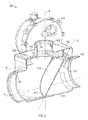
- FIG. 2 is a cross-sectional view of the diverter valve 20 of FIG. 1 in a closed position according to an embodiment of the invention.
- the diverter valve 20 has a valve body 102 that includes two separate passages through which air can pass through the diverter valve 20.
- the diverter valve 20 includes a first passage 104 that is aligned along axis A and a second passage 106 that is aligned along axis B.
- the first passage 104 includes an inlet 108 and an outlet 110 while the second passage 106 includes inlet 112 and an outlet 114.
- the inlet 108 is mechanically coupled to passage 44 while the outlet 110 is mechanically coupled to an inlet of passage 56 ( FIG. 1 ).
- the outlet 114 is coupled to an inlet of passage 58 ( FIG. 1 ).
- the inlet 108 and outlets 110, 114 are sized to minimize the pressure drop in the system from the ram inlet 12 ( FIG. 1 ) to the ram outlet ( FIG. 1 ).
- a flapper 120 that is generally semi-circular in shape is hingedly connected at pivot connection 116 and resides within valve body 102.
- the flapper 120 includes a raised edge 122 along its outer perimeter and which forms a sealing surface with both of the inner surface of the passage 104 and a generally planar portion 124 at inlet 112.
- a rotary actuator 118 is coupled to the valve body 102 and selectively pivots the flapper 120 approximately 45 degrees about pivot connection 116.
- the flapper 120 is pivoted in order to selectively open and close passages 104, 106 in response to a signal from the aircraft computer 18. For example, as shown in FIG. 2 , the flapper 120 is selectively deployed where raised edge 122 is contacting the inner surface of the passage 104.
- the flapper may be selectively deployed 45 degrees from axis C to axis D (which is parallel to planar portion 124) where the raised edge 122 is contacting the inner surface of generally planar portion 124 at inlet 112 thereby diverting the airflow that enters inlet 124 into outlet 110 and to the ram outlet 28 ( FIG. 1 ).
Abstract
Description
- The subject matter disclosed herein relates generally to aircraft environmental control and, more particularly, to systems and methods for enhanced motor cooling of a motor in a cabin air compressor.
- Environmental Control Systems (ECS's) are used on various types of aircraft for several purposes. For example, a cabin air conditioner in an ECS may be utilized to condition aircraft cabin air. The cabin air conditioner typically has one or more Cabin Air Compressors (CAC's) which compresses ram air entering the CAC from a ram air system before being delivered to the cabin air conditioner. The cabin air conditioner processes this compressed air from the CAC and brings it to a desired temperature for delivery to an aircraft cabin. The CAC's are typically driven by air-cooled electric motors that are cooled by a flow of cooling air typically drawn by the ram air system. The flow of cooling air is limited by the pressure drop at the ram air system outlet. If there is not enough cooling flow, the operation of the electric motor may be affected. Such a limitation may result in reduced performance of the cabin air conditioner.
- According to one aspect of the invention, a method for operation of an Environmental Control System (ECS), includes providing a ram air system including a ram inlet and a ram outlet; connecting a cabin air compressor motor to the ram inlet; connecting the cabin air compressor motor to a diverter valve; connecting the diverter valve to each of a dedicated outlet and the ram outlet; operating the diverter valve to provide fluid communication between the cabin air compressor motor and the ram outlet in a ground mode of operation; and operating the diverter valve to provide fluid communication between the cabin air compressor motor and the dedicated outlet in a flight mode of operation.
- In addition to one or more of the features described above, or as an alternative, further embodiments could include connecting the cabin air compressor motor to the ram inlet through a motor inlet passage.
- In addition to one or more of the features described above, or as an alternative, further embodiments could include connecting the cabin air compressor motor to the diverter valve through a diverter valve inlet.
- In addition to one or more of the features described above, or as an alternative, further embodiments could include providing a diverter valve having a first diverter inlet, a first diverter outlet, and a second diverter outlet.
- In addition to one or more of the features described above, or as an alternative, further embodiments could include connecting the cabin air compressor motor to the first diverter inlet through a motor outlet passage.
- In addition to one or more of the features described above, or as an alternative, further embodiments could include connecting the dedicated outlet to the first diverter outlet in the flight mode of operation.
- In addition to one or more of the features described above, or as an alternative, further embodiments could include connecting a second diverter outlet to the ram outlet in the ground mode of operation.
- In addition to one or more of the features described above, or as an alternative, further embodiments could include providing a diverter valve having a valve body including a first passage aligned along a first axis and a second passage aligned along a second axis that is orthogonal to the first axis; a rotary actuator mechanically connected to the valve body; and a flapper pivotally mounted within the valve body such that the flapper is movable by the rotary actuator in response to the flight mode of operation or the ground mode of operation.
- In addition to one or more of the features described above, or as an alternative, further embodiments could include generating a pressure differential between the ram inlet and the ram outlet with a ram air fan; and circulating ram air through the ram air system in response to the generating of the pressure differential.
- According to another aspect of the invention, an Environmental Control System (ECS) for an aircraft includes a ram air system having a ram inlet and a ram outlet. The ECS includes a cabin air compressor motor, a diverter valve, and a dedicated outlet. The cabin air compressor motor has a motor inlet passage and a motor outlet passage with the motor inlet passage being coupled to the ram inlet. The diverter valve includes a first diverter inlet, a first diverter outlet, and a second diverter outlet. The first diverter inlet is coupled to the motor outlet passage. The dedicated outlet is connected to the first diverter outlet in a flight mode of operation of the aircraft and the ram outlet is connected to the second diverter outlet in a ground mode of operation of the aircraft.
- In addition to one or more of the features described above, or as an alternative, further embodiments could include a motor outlet passage that connects the cabin air compressor motor to the first diverter inlet.
- 3 In addition to one or more of the features described above, or as an alternative, further embodiments could include a dedicated outlet passage that connects the first diverter outlet to the dedicated outlet.
- In addition to one or more of the features described above, or as an alternative, further embodiments could include a second diverter outlet passage that connects the ram outlet to the second diverter outlet.
- In addition to one or more of the features described above, or as an alternative, further embodiments could include a flight computer electronically connected to the diverter valve, the flight computer being configured to direct airflow from the cabin air compressor motor to the first diverter outlet in the flight mode of operation.
- In addition to one or more of the features described above, or as an alternative, further embodiments could include a flight computer electronically connected to the diverter valve, the flight computer being configured to direct airflow from the cabin air compressor motor to the second diverter outlet in the ground mode of operation.
- In addition to one or more of the features described above, or as an alternative, further embodiments could include a valve body including a first passage aligned along a first axis and a second passage aligned along a second axis that is orthogonal to the first axis; a rotary actuator mechanically connected to the valve body; and a flapper pivotally mounted within the valve body such that the flapper is movable by the rotary actuator in response to the flight mode of operation or the ground mode of operation.
- According to another aspect of the invention, a diverter valve includes a valve body including a first passage aligned along a first axis and a second passage aligned along a second axis that is orthogonal to the first axis; a rotary actuator mechanically connected to the valve body; and a flapper pivotally mounted within the valve body such that the flapper is movable by the rotary actuator in response to a flight mode of operation or a ground mode of operation.
- In addition to one or more of the features described above, or as an alternative, further embodiments could include a flapper that includes a sealing edge on an outer periphery of the flapper.
- In addition to one or more of the features described above, or as an alternative, further embodiments could include a first passage with a first passage inlet and a first passage outlet.
- In addition to one or more of the features described above, or as an alternative, further embodiments could include a second passage with a second passage inlet and a second passage outlet.
- Other aspects, features, and techniques of the invention will become more apparent from the following description taken in conjunction with the drawings.
- The subject matter, which is regarded as the invention, is particularly pointed out and distinctly claimed in the claims at the conclusion of the specification. The foregoing and other features, and advantages of the invention are apparent from the following detailed description taken in conjunction with the accompanying drawings in which like elements are numbered alike in the several FIGURES:
-
FIG. 1 is a partial schematic view of an ECS depicting motor cooling flow according to an embodiment of the invention; and -
FIG. 2 is a cross-sectional view of a diverter valve in the ECS ofFIG. 1 according to an embodiment of the invention. - Other aspects, features, and techniques of the invention will become more apparent from the following description taken in conjunction with the drawings.
- Embodiments disclosed herein include a diverter valve that determines operation of a ram circuit in ground mode or in flight mode of an aircraft. The diverter valve is coupled to one or more passages to divert exhaust airflow through a dedicated outlet and away from a ram outlet in flight mode. Diverting the exhaust airflow may minimize or eliminate the backpressure that can affect the motor cooling airflow through the ram air system.
- Referring now to the drawings,
FIG. 1 illustrates a partial schematic view of portions of an Environmental Control System (ECS) 10 for a dual mode of operation of an aircraft. As illustrated, the ECS 10 may be a refrigeration or air cycle subsystem and includes CAC's 14a, 14b,CAC motors diverter valve 20,ozone converter 22,ram air duct 24, anaircraft computer 18, and an air conditioner (A/C)pack 26. Generally, the CAC's 14a, 14b are driven by theirrespective CAC motors valve 12. In another embodiment, the air source may be bleed air from a turbine engine. The compressed air from the CAC's 14a, 14b is delivered to anozone converter 22. Theozone converter 22 converts ozone into oxygen. The reduced-ozone compressed air is then cooled by one ormore heat exchangers 46 and is communicated through apassage 48 to an A/C pack 26. It should be appreciated that although two CAC's 14a, 14b are shown being used in a single A/C pack 26, theECS 10 may include, in other embodiments, substantially the same single CAC or substantially the same multiple CAC's for each A/C pack 26. - Also, ram air is drawn through
passages respective CAC motors CAC motors CAC motors ram inlet 12 to theram outlet 28 in the ram air system 30 (shown on the right inFIG. 1 ) and the amount of cooling ram air is typically modulated by ram doors on the aircraft. In a ground mode of operation (i.e., when the aircraft is on the ground), the Ram Air Fan (RAF) 54 creates a pressure differential between theram inlet 12 andram outlet 28 which draws ram air through theram inlet 12 and to be exited at theram outlet 28 through theram air duct 24. However, during cruise and other flight segments, the RAF 54 is bypassed using the Ram Bypass Check valve 62. Backpressure caused by the ram doors at theram outlet 28 limits the amount of cooling airflow that may be drawn through theram air duct 24. This limits the cooling airflow that can be provided to cool theCAC motors diverter valve 20 is provided alongpassage 44 to minimize or eliminate the backpressure from the ram doors during cruise. Additionally, during other flight modes such as, for example, during takeoff or landing, thediverter valve 20 does not add pressure loss in the ram air system 30 that may affect efficiency of theCAC motors diverter valve 20 may prevent theram outlet 28 from throttling the cooling ram air flow through the ram air system 30. - In one embodiment, the
aircraft computer 18 communicates with theECS 10 to control operation of thediverter valve 20 during the various flight modes. In an embodiment, theaircraft computer 18 receives data through the various on-board accelerometers, sensors, and avionics systems to determine if, for example, the flaps or slats are being deployed, the aircraft is in cruise, ascent, descent, or on the ground. Theflight computer 18 includes control algorithms to control operation of thediverter valve 20 in response to receiving the input data for the various flight modes including ground mode or flight mode. In an embodiment, theflight computer 18 may include memory to store instructions that are executed by a processor. The executable instructions may be stored or organized in any manner and at any level of abstraction, such as in connection with managing the ram airflow through theECS 10. The microprocessor can be any type of processor (CPU), including a general purpose processor, a digital signal processor, a microcontroller, an application specific integrated circuit (ASIC), a field programmable gate array, or the like. Also, in embodiments, the memory may include random access memory (RAM), read only memory (ROM), or other electronic, optical, magnetic, or any other computer readable medium onto which is stored the data and control algorithms for controlling thediverter valve 20 and other operational data for the aircraft. - In a ground mode cooling path, a cooling airflow such as ram air (also referred to as ambient air) flows from a valve in ram inlet 12 (shown on the left in
FIG. 1 ) into theCAC 14a throughCAC inlet 34. The ram air enters theCAC 14a throughpassage 32. Similarly, ambient air fromram inlet 12 flows intoCAC 14b throughCAC inlet 38. The ram air enters theCAC 14b throughpassage 36. The ram air that flows intopassages respective CAC motors CAC motors respective passages passages passage 44 and enters thediverter valve 20 to form a combined heated airflow. The combined heated airflow passes throughdiverter valve 20 intopassage 56. This air is drawn toward theram outlet 28 byRAF 54. TheRAF 54 generates a sufficient pressure differential between theram inlet 12 and theram outlet 28 to pull ram air through the ram air system 30. - In a flight mode cooling path, a cooling airflow such as ram air (also referred to as ambient air) flows from a valve in
ram inlet 12 into theCAC 14a throughCAC inlet 34. The ram air enters theCAC 14a throughpassage 32. Similarly, ambient air fromram inlet 12 flows intoCAC 14b throughCAC inlet 38. The ram air enters theCAC 14b throughpassage 36. The ram air flows that intopassages respective CAC motors CAC motors respective passages passages passage 44 and enters thediverter valve 20 to form a combined heated airflow. The combined heated airflow is diverted intopassage 58 by thediverter valve 20 and exits at adedicated exhaust 60. Thededicated exhaust 60 provides efficient cooling by minimizing the influence from any modulation valves or any other ram doors in the aircraft. As a result, discharging the air heated by theCAC motors dedicated outlet 60 may improve the cooling ram air circulating in the ram air system 30. For example, discharging the airflow away from theram outlet 28 limits the backpressure at theram outlet 28 that is caused by the discharge from theCAC motors dedicated exhaust 60 may be sized for cruise operation in order to minimize any leakage from thepassage 56 through thededicated exhaust 60 during the cruise mode. Additional benefits include minimal leakage from thepassage 56 into thededicated exhaust 60 during the ground mode. -
FIG. 2 is a cross-sectional view of thediverter valve 20 ofFIG. 1 in a closed position according to an embodiment of the invention. Thediverter valve 20 has avalve body 102 that includes two separate passages through which air can pass through thediverter valve 20. Particularly, thediverter valve 20 includes afirst passage 104 that is aligned along axis A and asecond passage 106 that is aligned along axis B. Thefirst passage 104 includes aninlet 108 and anoutlet 110 while thesecond passage 106 includesinlet 112 and anoutlet 114. Theinlet 108 is mechanically coupled topassage 44 while theoutlet 110 is mechanically coupled to an inlet of passage 56 (FIG. 1 ). Also, theoutlet 114 is coupled to an inlet of passage 58 (FIG. 1 ). Theinlet 108 andoutlets FIG. 1 ) to the ram outlet (FIG. 1 ). - Also, a
flapper 120 that is generally semi-circular in shape is hingedly connected atpivot connection 116 and resides withinvalve body 102. Theflapper 120 includes a raisededge 122 along its outer perimeter and which forms a sealing surface with both of the inner surface of thepassage 104 and a generallyplanar portion 124 atinlet 112. Arotary actuator 118 is coupled to thevalve body 102 and selectively pivots theflapper 120 approximately 45 degrees aboutpivot connection 116. Theflapper 120 is pivoted in order to selectively open andclose passages aircraft computer 18. For example, as shown inFIG. 2 , theflapper 120 is selectively deployed where raisededge 122 is contacting the inner surface of thepassage 104. This contact diverts the airflow that entersinlet 124 intooutlet 114 and to the dedicated exhaust 60 (FIG. 1 ). Also, the flapper may be selectively deployed 45 degrees from axis C to axis D (which is parallel to planar portion 124) where the raisededge 122 is contacting the inner surface of generallyplanar portion 124 atinlet 112 thereby diverting the airflow that entersinlet 124 intooutlet 110 and to the ram outlet 28 (FIG. 1 ). - The terminology used herein is for the purpose of describing particular embodiments only and is not intended to be limiting of the invention. While the description of the present invention has been presented for purposes of illustration and description, it is not intended to be exhaustive or limited to the invention in the form disclosed. Many modifications, variations, alterations, substitutions, or equivalent arrangement not hereto described will be apparent to those of ordinary skill in the art without departing from the scope and spirit of the invention. Additionally, while the various embodiment of the invention have been described, it is to be understood that aspects of the invention may include only some of the described embodiments. Accordingly, the invention is not to be seen as limited by the foregoing description, but is only limited by the scope of the appended claims.
Claims (15)
- An Environmental Control System (ECS) (10) for an aircraft, comprising:a ram air system including a ram inlet (12) and a ram outlet (28);a cabin air compressor motor including a motor inlet passage and a motor outlet passage, the motor inlet passage being coupled to the ram inlet (12);a diverter valve (20) including a first diverter inlet, a first diverter outlet, and a second diverter outlet, the first diverter inlet being coupled to the motor outlet passage; anda dedicated outlet (60) selectively connected to the first diverter outlet in a flight mode of operation of the aircraft;wherein the ram outlet (28) is connected to the second diverter outlet in a ground mode of operation of the aircraft.
- The Environmental Control System of claim 1, further comprising:a motor outlet passage that connects the cabin air compressor motor to the first diverter inlet.
- The Environmental Control System of claim 1, further comprising:a dedicated outlet passage that connects the first diverter outlet to the dedicated outlet.
- The Environmental Control System of claim 1, further comprising:a second diverter outlet passage that connects the ram outlet (28) to the second diverter outlet.
- The Environmental Control System of claim 1, further comprising:a flight computer (18) electronically connected to the diverter valve (20), the flight computer directs airflow from the cabin air compressor motor to the first diverter outlet in the flight mode of operation.
- The Environmental Control System of claim 1, further comprising:a flight computer (18) electronically connected to the diverter valve (20), the flight computer directs airflow from the cabin air compressor motor to the second diverter outlet in the ground mode of operation.
- The Environmental Control System of claim 1, wherein the diverter valve (20) further comprises:a valve body (102) including a first passage (104) aligned along a first axis and a second passage (106) aligned along a second axis that is orthogonal to the first axis;a rotary actuator (118) mechanically connected to the valve body (102); anda flapper (120) pivotally mounted within the valve body (102) such that the flapper is movable by the rotary actuator in response to the flight mode of operation or the ground mode of operation.
- A dual mode method of operation of an Environmental Control System (ECS), comprising:providing a ram air system including a ram inlet (12) and a ram outlet (28);connecting a cabin air compressor motor to the ram inlet (12);connecting the cabin air compressor motor to a diverter valve (20);connecting the diverter valve (20) to each of a dedicated outlet (60) and the ram outlet (28);operating the diverter valve (20) to provide fluid communication between the cabin air compressor motor and the ram outlet (28) in a ground mode of operation; andoperating the diverter valve (20) to provide fluid communication between the cabin air compressor motor and the dedicated outlet in a flight mode of operation.
- The dual mode method of operation of claim 8, further comprising:connecting the cabin air compressor motor to the ram inlet (12) through a motor inlet passage.
- The dual mode method of operation of claim 8, further comprising:connecting the cabin air compressor motor to the diverter valve through a diverter valve inlet.
- The dual mode method of operation of claim 8, further comprising:providing a diverter valve having a first diverter inlet, a first diverter outlet, and a second diverter outlet, and connecting the cabin air compressor motor to the first diverter inlet through a motor outlet passage.
- The dual mode method of operation of claim 11, further comprising:connecting the dedicated outlet (60) to the first diverter outlet in the flight mode of operation.
- The dual mode method of operation of claim 11, further comprising:connecting the second diverter outlet to the ram outlet (28) in the ground mode of operation.
- The dual mode of operation of claim 8, further comprising:providing the diverter valve (20) including:a valve body (102) including a first passage (104) aligned along a first axis and a second passage (106) aligned along a second axis that is orthogonal to the first axis;a rotary actuator (118) mechanically connected to the valve body (102); anda flapper (120) pivotally mounted within the valve body (102) such that the flapper is movable by the rotary actuator (118) in response to the flight mode of operation or the ground mode of operation.
- The dual mode method of operation of claim 11, further comprising:generating a pressure differential between the ram inlet (12) and the ram outlet (28) with a ram air fan; andcirculating ram air through the ram air system in response to the generating of the pressure differential.
Applications Claiming Priority (1)
| Application Number | Priority Date | Filing Date | Title |
|---|---|---|---|
| US13/930,549 US10184494B2 (en) | 2013-06-28 | 2013-06-28 | Enhance motor cooling system and method |
Publications (3)
| Publication Number | Publication Date |
|---|---|
| EP2837563A2 true EP2837563A2 (en) | 2015-02-18 |
| EP2837563A3 EP2837563A3 (en) | 2015-10-28 |
| EP2837563B1 EP2837563B1 (en) | 2017-08-02 |
Family
ID=50982813
Family Applications (1)
| Application Number | Title | Priority Date | Filing Date |
|---|---|---|---|
| EP14174067.0A Active EP2837563B1 (en) | 2013-06-28 | 2014-06-26 | Enhanced motor cooling system and method |
Country Status (2)
| Country | Link |
|---|---|
| US (4) | US10184494B2 (en) |
| EP (1) | EP2837563B1 (en) |
Families Citing this family (12)
| Publication number | Priority date | Publication date | Assignee | Title |
|---|---|---|---|---|
| US10184494B2 (en) | 2013-06-28 | 2019-01-22 | Hamilton Sundstrand Corporation | Enhance motor cooling system and method |
| US9709178B2 (en) | 2015-06-16 | 2017-07-18 | Hamilton Sundstrand Corporation | Flow diverting flapper |
| KR101935847B1 (en) * | 2015-07-17 | 2019-01-07 | 인핸스 인코퍼레이티드 | Method and system for modifying machine instructions in compiled software |
| US9683678B2 (en) | 2015-08-13 | 2017-06-20 | Hamilton Sundstrand Corporation | Heat exchanging valve arrangement |
| CN106892121B (en) * | 2015-12-21 | 2019-10-18 | 中国航空工业集团公司西安飞机设计研究所 | A kind of aircraft environmental control system control method |
| US11459110B2 (en) * | 2016-04-22 | 2022-10-04 | Hamilton Sunstrand Corporation | Environmental control system utilizing two pass secondary heat exchanger and cabin pressure assist |
| US20180162537A1 (en) | 2016-12-09 | 2018-06-14 | United Technologies Corporation | Environmental control system air circuit |
| US10486816B2 (en) | 2017-04-07 | 2019-11-26 | Hamilton Sundstrand Corporation | Fan bypass and shutoff check valve |
| US10931170B2 (en) | 2017-05-10 | 2021-02-23 | Hamilton Sundstrand Corporation | Motor cooling utilizing cabin air |
| US10618662B2 (en) * | 2018-03-19 | 2020-04-14 | Hamilton Sundstrand Corporation | Ram flow control with predicted ram air flow |
| US11174757B2 (en) | 2020-01-20 | 2021-11-16 | Raytheon Technologies Corporation | Externally replaceable valve assembly for a turbine engine |
| US11486315B2 (en) | 2020-11-06 | 2022-11-01 | Ge Aviation Systems Llc | Combustion engine including turbomachine |
Family Cites Families (57)
| Publication number | Priority date | Publication date | Assignee | Title |
|---|---|---|---|---|
| US1081744A (en) | 1913-12-16 | Richard L Hubbard | Muffler cut-out. | |
| US1065467A (en) | 1910-04-13 | 1913-06-24 | Arthur Piel | Muffler cut-out. |
| US1514090A (en) * | 1922-03-25 | 1924-11-04 | Leroy M Lewis | Alarm check valve |
| US1585951A (en) | 1924-12-30 | 1926-05-25 | Otis L Waller | Pipe coupling |
| US3270775A (en) * | 1963-04-09 | 1966-09-06 | Gen Electric | Diverter valve assembly |
| GB994856A (en) * | 1963-04-10 | 1965-06-10 | Normalair Ltd | Improvements in or relating to air conditioning systems |
| US3521659A (en) * | 1967-05-18 | 1970-07-28 | Blaw Knox Co | High temperature valve for throttling or three-way application |
| US3428242A (en) * | 1967-06-02 | 1969-02-18 | United Aircraft Corp | Unitary simple/bootstrap air cycle system |
| US4074889A (en) * | 1975-02-28 | 1978-02-21 | Honeywell G.M.B.H. | Rotary valve |
| US4021215A (en) * | 1976-05-03 | 1977-05-03 | United Technologies Corporation | Dual combined cycle air-conditioning system |
| US4263786A (en) * | 1979-07-10 | 1981-04-28 | The Boeing Company | Fuel conserving air-conditioning apparatus and method for aircraft |
| US4419926A (en) * | 1980-09-02 | 1983-12-13 | Lockheed Corporation | ESC energy recovery system for fuel-efficient aircraft |
| US4430867A (en) * | 1981-08-24 | 1984-02-14 | United Technologies Corporation | Air cycle refrigeration system |
| US4462561A (en) * | 1982-05-27 | 1984-07-31 | Lockheed Corporation | Energy efficient ECS powered by a variable voltage/variable frequency power system |
| US4546939A (en) * | 1982-05-27 | 1985-10-15 | Lockheed Corporation | Energy efficient ECS powered by a variable voltage/variable frequency power system |
| US4494372A (en) * | 1983-06-10 | 1985-01-22 | Lockheed Corporation | Multi role primary/auxiliary power system with engine start capability for aircraft |
| US4718457A (en) | 1986-06-20 | 1988-01-12 | Luger G William | Diverter valve |
| US4963174A (en) * | 1989-12-12 | 1990-10-16 | Payne George K | Hybrid vapor cycle/air cycle environmental control system |
| GB9020297D0 (en) * | 1990-09-17 | 1990-10-31 | Grovag Grossventiltech | Diverter valves |
| US5461882A (en) * | 1994-07-22 | 1995-10-31 | United Technologies Corporation | Regenerative condensing cycle |
| US5704218A (en) * | 1996-04-08 | 1998-01-06 | United Technologies Corporation | Integrated environmental control system |
| JPH10121996A (en) * | 1996-10-18 | 1998-05-12 | Sumitomo Electric Ind Ltd | Three way valve and exhaust gas processing device using it |
| US6182699B1 (en) | 1997-02-13 | 2001-02-06 | David R. Hawkes | Diverter valve for improved flow control |
| US5967461A (en) * | 1997-07-02 | 1999-10-19 | Mcdonnell Douglas Corp. | High efficiency environmental control systems and methods |
| DE69805795T2 (en) * | 1997-07-11 | 2003-01-02 | Honeywell Int Inc | AIR CIRCUIT AIR CONDITIONING CONTROL SYSTEM WITH CONDENSATION SUPPORTED BY DUMP CYCLE |
| US5899805A (en) * | 1997-10-20 | 1999-05-04 | United Technologies Corporation | Distribution damper valve |
| US5887445A (en) * | 1997-11-11 | 1999-03-30 | Alliedsignal Inc. | Two spool environmental control system |
| US6199387B1 (en) * | 1999-07-30 | 2001-03-13 | Liebherr-Aerospace Lindenberg Gmbh | Air-conditioning system for airplane cabin |
| US6189324B1 (en) * | 1999-10-05 | 2001-02-20 | Samuel B. Williams | Environment control unit for turbine engine |
| US6257003B1 (en) * | 2000-08-04 | 2001-07-10 | Hamilton Sundstrand Corporation | Environmental control system utilizing two air cycle machines |
| US6681592B1 (en) * | 2001-02-16 | 2004-01-27 | Hamilton Sundstrand Corporation | Electrically driven aircraft cabin ventilation and environmental control system |
| US6948331B1 (en) * | 2003-09-12 | 2005-09-27 | Norhrop Grumman Corporation | Environmental control system for an aircraft |
| US7306646B2 (en) * | 2004-04-08 | 2007-12-11 | Parker-Hannifin Corporation | Utilization of compressor surge control air in an aircraft on-board inert gas generating system |
| US7086416B2 (en) * | 2004-05-27 | 2006-08-08 | Zimmerman & Jansen, Inc. | Valve assembly having a compensating gate |
| US20070113579A1 (en) * | 2004-08-25 | 2007-05-24 | Claeys Henry M | Low energy electric air cycle with portal shroud cabin air compressor |
| US7300494B2 (en) * | 2005-02-24 | 2007-11-27 | Hamilton Sundstrand Corporation | On-board inert gas generation system with compressor surge protection |
| US7644792B2 (en) * | 2006-01-06 | 2010-01-12 | Hamilton Sundstrand | Motor cooling system |
| US7607318B2 (en) * | 2006-05-25 | 2009-10-27 | Honeywell International Inc. | Integrated environmental control and auxiliary power system for an aircraft |
| GB0615143D0 (en) * | 2006-07-29 | 2006-09-06 | Cummins Turbo Tech Ltd | Multi-stage turbocharger system |
| DE102006052234A1 (en) | 2006-11-06 | 2008-05-08 | Liebherr-Aerospace Lindenberg Gmbh | Compressor arrangement for use in air conditioning system, has suction chamber, which is directly connected upstream of two compressors commonly on suction side |
| JP5032109B2 (en) * | 2006-12-27 | 2012-09-26 | 株式会社ツカサ | Flow path switching device for transferring powder |
| DE102007032306A1 (en) * | 2007-07-11 | 2009-01-22 | Airbus Deutschland Gmbh | Air conditioning system for aircraft cabins |
| DE102007052818A1 (en) | 2007-11-06 | 2009-05-07 | Liebherr-Aerospace Lindenberg Gmbh | Airplane, has cooling air line extending from ventilation system to air conditioning system such that motor cooling air led through air line is supplied to motor or area, in which motor is provided |
| US20110233433A1 (en) | 2010-03-29 | 2011-09-29 | Dehais John M | Sealed flapper diverter valve |
| US20130118624A1 (en) | 2010-03-29 | 2013-05-16 | Hamilton Sundstrand Corporation | Sealed flapper diverter valve |
| GB2499577A (en) * | 2011-11-29 | 2013-08-28 | Eaton Aerospace Ltd | Aircraft on board inert gas generation system |
| GB2499578A (en) * | 2011-11-29 | 2013-08-28 | Eaton Aerospace Ltd | Aircraft on board inert gas generation system |
| GB2499576A (en) * | 2011-11-29 | 2013-08-28 | Eaton Aerospace Ltd | Aircraft on board inert gas generation system |
| US9016075B1 (en) * | 2012-01-04 | 2015-04-28 | The Boeing Company | Aircraft environmental control system and method |
| US9254920B2 (en) * | 2012-05-30 | 2016-02-09 | General Electric Company | Aircraft energy management system including engine fan discharge air boosted environmental control system |
| US9457908B2 (en) * | 2012-09-20 | 2016-10-04 | Hamilton Sundstrand Corporation | Self-cooled motor driven compressor |
| US9669936B1 (en) | 2012-10-24 | 2017-06-06 | The Boeing Company | Aircraft air conditioning systems and methods |
| US10184494B2 (en) | 2013-06-28 | 2019-01-22 | Hamilton Sundstrand Corporation | Enhance motor cooling system and method |
| US9611947B2 (en) * | 2015-06-09 | 2017-04-04 | Ge Aviation Systems Llc | Valve assembly and method of controlling flow of fluid |
| US9709178B2 (en) | 2015-06-16 | 2017-07-18 | Hamilton Sundstrand Corporation | Flow diverting flapper |
| US10144521B2 (en) * | 2015-08-04 | 2018-12-04 | Hamilton Sundstrand Corporation | Electric compressor for use with a wing anti-ice system |
| US10758950B2 (en) * | 2018-08-30 | 2020-09-01 | Loos Machine & Automation | Valve for a clean in place system |
-
2013
- 2013-06-28 US US13/930,549 patent/US10184494B2/en active Active
-
2014
- 2014-06-26 EP EP14174067.0A patent/EP2837563B1/en active Active
-
2018
- 2018-10-11 US US16/157,147 patent/US11156233B2/en active Active
- 2018-10-11 US US16/157,157 patent/US11391299B2/en active Active
-
2021
- 2021-10-05 US US17/494,207 patent/US11959499B2/en active Active
Non-Patent Citations (1)
| Title |
|---|
| None |
Also Published As
| Publication number | Publication date |
|---|---|
| US20190040877A1 (en) | 2019-02-07 |
| US20150004011A1 (en) | 2015-01-01 |
| US10184494B2 (en) | 2019-01-22 |
| US11959499B2 (en) | 2024-04-16 |
| EP2837563A3 (en) | 2015-10-28 |
| EP2837563B1 (en) | 2017-08-02 |
| US11156233B2 (en) | 2021-10-26 |
| US20190040876A1 (en) | 2019-02-07 |
| US20220025907A1 (en) | 2022-01-27 |
| US11391299B2 (en) | 2022-07-19 |
Similar Documents
| Publication | Publication Date | Title |
|---|---|---|
| US11959499B2 (en) | Enhanced motor cooling system and method | |
| US9328650B2 (en) | Engine cooling system | |
| EP3543131B1 (en) | Cooling system, air conditioning pack, and method for conditioning air | |
| EP2845803A1 (en) | An environmental control system (ECS) comprising a bypass for an air cycle machine (ACM) | |
| EP2602191B1 (en) | Motor driven cabin air compressor with variable diffuser | |
| US20070113579A1 (en) | Low energy electric air cycle with portal shroud cabin air compressor | |
| EP1806288B1 (en) | Aircraft motor cooling system and Method | |
| CN103946555B (en) | Surge during the startup of chiller compressor stops | |
| EP3511248B1 (en) | Vehicle air conditioning pack with air cycle assembly | |
| EP3760542A1 (en) | Environmental control system of an aircraft | |
| US8657568B2 (en) | Variable turbine nozzle and valve | |
| US9895953B2 (en) | Vehicle heat exchanger air flow control system | |
| US9969241B2 (en) | Vehicle heat exchanger air flow control system | |
| EP3838763B1 (en) | Air cycle machines, air cycle machine systems, and methods of controlling air flow in air cycle machines | |
| EP3757389B1 (en) | Motor cooling systems | |
| WO2022091276A1 (en) | Compressed air supply system |
Legal Events
| Date | Code | Title | Description |
|---|---|---|---|
| 17P | Request for examination filed |
Effective date: 20140626 |
|
| AK | Designated contracting states |
Kind code of ref document: A2 Designated state(s): AL AT BE BG CH CY CZ DE DK EE ES FI FR GB GR HR HU IE IS IT LI LT LU LV MC MK MT NL NO PL PT RO RS SE SI SK SM TR |
|
| AX | Request for extension of the european patent |
Extension state: BA ME |
|
| PUAI | Public reference made under article 153(3) epc to a published international application that has entered the european phase |
Free format text: ORIGINAL CODE: 0009012 |
|
| PUAL | Search report despatched |
Free format text: ORIGINAL CODE: 0009013 |
|
| AK | Designated contracting states |
Kind code of ref document: A3 Designated state(s): AL AT BE BG CH CY CZ DE DK EE ES FI FR GB GR HR HU IE IS IT LI LT LU LV MC MK MT NL NO PL PT RO RS SE SI SK SM TR |
|
| AX | Request for extension of the european patent |
Extension state: BA ME |
|
| RIC1 | Information provided on ipc code assigned before grant |
Ipc: B64D 13/06 20060101AFI20150924BHEP |
|
| R17P | Request for examination filed (corrected) |
Effective date: 20160428 |
|
| RBV | Designated contracting states (corrected) |
Designated state(s): AL AT BE BG CH CY CZ DE DK EE ES FI FR GB GR HR HU IE IS IT LI LT LU LV MC MK MT NL NO PL PT RO RS SE SI SK SM TR |
|
| GRAP | Despatch of communication of intention to grant a patent |
Free format text: ORIGINAL CODE: EPIDOSNIGR1 |
|
| INTG | Intention to grant announced |
Effective date: 20170203 |
|
| GRAS | Grant fee paid |
Free format text: ORIGINAL CODE: EPIDOSNIGR3 |
|
| GRAA | (expected) grant |
Free format text: ORIGINAL CODE: 0009210 |
|
| AK | Designated contracting states |
Kind code of ref document: B1 Designated state(s): AL AT BE BG CH CY CZ DE DK EE ES FI FR GB GR HR HU IE IS IT LI LT LU LV MC MK MT NL NO PL PT RO RS SE SI SK SM TR |
|
| REG | Reference to a national code |
Ref country code: CH Ref legal event code: EP Ref country code: AT Ref legal event code: REF Ref document number: 914141 Country of ref document: AT Kind code of ref document: T Effective date: 20170815 |
|
| REG | Reference to a national code |
Ref country code: IE Ref legal event code: FG4D |
|
| REG | Reference to a national code |
Ref country code: DE Ref legal event code: R096 Ref document number: 602014012444 Country of ref document: DE |
|
| REG | Reference to a national code |
Ref country code: NL Ref legal event code: MP Effective date: 20170802 |
|
| REG | Reference to a national code |
Ref country code: AT Ref legal event code: MK05 Ref document number: 914141 Country of ref document: AT Kind code of ref document: T Effective date: 20170802 |
|
| REG | Reference to a national code |
Ref country code: LT Ref legal event code: MG4D |
|
| PG25 | Lapsed in a contracting state [announced via postgrant information from national office to epo] |
Ref country code: LT Free format text: LAPSE BECAUSE OF FAILURE TO SUBMIT A TRANSLATION OF THE DESCRIPTION OR TO PAY THE FEE WITHIN THE PRESCRIBED TIME-LIMIT Effective date: 20170802 Ref country code: SE Free format text: LAPSE BECAUSE OF FAILURE TO SUBMIT A TRANSLATION OF THE DESCRIPTION OR TO PAY THE FEE WITHIN THE PRESCRIBED TIME-LIMIT Effective date: 20170802 Ref country code: AT Free format text: LAPSE BECAUSE OF FAILURE TO SUBMIT A TRANSLATION OF THE DESCRIPTION OR TO PAY THE FEE WITHIN THE PRESCRIBED TIME-LIMIT Effective date: 20170802 Ref country code: HR Free format text: LAPSE BECAUSE OF FAILURE TO SUBMIT A TRANSLATION OF THE DESCRIPTION OR TO PAY THE FEE WITHIN THE PRESCRIBED TIME-LIMIT Effective date: 20170802 Ref country code: NO Free format text: LAPSE BECAUSE OF FAILURE TO SUBMIT A TRANSLATION OF THE DESCRIPTION OR TO PAY THE FEE WITHIN THE PRESCRIBED TIME-LIMIT Effective date: 20171102 Ref country code: NL Free format text: LAPSE BECAUSE OF FAILURE TO SUBMIT A TRANSLATION OF THE DESCRIPTION OR TO PAY THE FEE WITHIN THE PRESCRIBED TIME-LIMIT Effective date: 20170802 Ref country code: FI Free format text: LAPSE BECAUSE OF FAILURE TO SUBMIT A TRANSLATION OF THE DESCRIPTION OR TO PAY THE FEE WITHIN THE PRESCRIBED TIME-LIMIT Effective date: 20170802 |
|
| PG25 | Lapsed in a contracting state [announced via postgrant information from national office to epo] |
Ref country code: BG Free format text: LAPSE BECAUSE OF FAILURE TO SUBMIT A TRANSLATION OF THE DESCRIPTION OR TO PAY THE FEE WITHIN THE PRESCRIBED TIME-LIMIT Effective date: 20171102 Ref country code: RS Free format text: LAPSE BECAUSE OF FAILURE TO SUBMIT A TRANSLATION OF THE DESCRIPTION OR TO PAY THE FEE WITHIN THE PRESCRIBED TIME-LIMIT Effective date: 20170802 Ref country code: ES Free format text: LAPSE BECAUSE OF FAILURE TO SUBMIT A TRANSLATION OF THE DESCRIPTION OR TO PAY THE FEE WITHIN THE PRESCRIBED TIME-LIMIT Effective date: 20170802 Ref country code: IS Free format text: LAPSE BECAUSE OF FAILURE TO SUBMIT A TRANSLATION OF THE DESCRIPTION OR TO PAY THE FEE WITHIN THE PRESCRIBED TIME-LIMIT Effective date: 20171202 Ref country code: PL Free format text: LAPSE BECAUSE OF FAILURE TO SUBMIT A TRANSLATION OF THE DESCRIPTION OR TO PAY THE FEE WITHIN THE PRESCRIBED TIME-LIMIT Effective date: 20170802 Ref country code: LV Free format text: LAPSE BECAUSE OF FAILURE TO SUBMIT A TRANSLATION OF THE DESCRIPTION OR TO PAY THE FEE WITHIN THE PRESCRIBED TIME-LIMIT Effective date: 20170802 Ref country code: GR Free format text: LAPSE BECAUSE OF FAILURE TO SUBMIT A TRANSLATION OF THE DESCRIPTION OR TO PAY THE FEE WITHIN THE PRESCRIBED TIME-LIMIT Effective date: 20171103 |
|
| PG25 | Lapsed in a contracting state [announced via postgrant information from national office to epo] |
Ref country code: RO Free format text: LAPSE BECAUSE OF FAILURE TO SUBMIT A TRANSLATION OF THE DESCRIPTION OR TO PAY THE FEE WITHIN THE PRESCRIBED TIME-LIMIT Effective date: 20170802 Ref country code: CZ Free format text: LAPSE BECAUSE OF FAILURE TO SUBMIT A TRANSLATION OF THE DESCRIPTION OR TO PAY THE FEE WITHIN THE PRESCRIBED TIME-LIMIT Effective date: 20170802 Ref country code: DK Free format text: LAPSE BECAUSE OF FAILURE TO SUBMIT A TRANSLATION OF THE DESCRIPTION OR TO PAY THE FEE WITHIN THE PRESCRIBED TIME-LIMIT Effective date: 20170802 |
|
| REG | Reference to a national code |
Ref country code: DE Ref legal event code: R097 Ref document number: 602014012444 Country of ref document: DE |
|
| PG25 | Lapsed in a contracting state [announced via postgrant information from national office to epo] |
Ref country code: SM Free format text: LAPSE BECAUSE OF FAILURE TO SUBMIT A TRANSLATION OF THE DESCRIPTION OR TO PAY THE FEE WITHIN THE PRESCRIBED TIME-LIMIT Effective date: 20170802 Ref country code: EE Free format text: LAPSE BECAUSE OF FAILURE TO SUBMIT A TRANSLATION OF THE DESCRIPTION OR TO PAY THE FEE WITHIN THE PRESCRIBED TIME-LIMIT Effective date: 20170802 Ref country code: SK Free format text: LAPSE BECAUSE OF FAILURE TO SUBMIT A TRANSLATION OF THE DESCRIPTION OR TO PAY THE FEE WITHIN THE PRESCRIBED TIME-LIMIT Effective date: 20170802 Ref country code: IT Free format text: LAPSE BECAUSE OF FAILURE TO SUBMIT A TRANSLATION OF THE DESCRIPTION OR TO PAY THE FEE WITHIN THE PRESCRIBED TIME-LIMIT Effective date: 20170802 |
|
| REG | Reference to a national code |
Ref country code: FR Ref legal event code: PLFP Year of fee payment: 5 |
|
| PLBE | No opposition filed within time limit |
Free format text: ORIGINAL CODE: 0009261 |
|
| STAA | Information on the status of an ep patent application or granted ep patent |
Free format text: STATUS: NO OPPOSITION FILED WITHIN TIME LIMIT |
|
| 26N | No opposition filed |
Effective date: 20180503 |
|
| PG25 | Lapsed in a contracting state [announced via postgrant information from national office to epo] |
Ref country code: SI Free format text: LAPSE BECAUSE OF FAILURE TO SUBMIT A TRANSLATION OF THE DESCRIPTION OR TO PAY THE FEE WITHIN THE PRESCRIBED TIME-LIMIT Effective date: 20170802 |
|
| REG | Reference to a national code |
Ref country code: DE Ref legal event code: R119 Ref document number: 602014012444 Country of ref document: DE |
|
| REG | Reference to a national code |
Ref country code: CH Ref legal event code: PL |
|
| REG | Reference to a national code |
Ref country code: BE Ref legal event code: MM Effective date: 20180630 |
|
| REG | Reference to a national code |
Ref country code: IE Ref legal event code: MM4A |
|
| PG25 | Lapsed in a contracting state [announced via postgrant information from national office to epo] |
Ref country code: MC Free format text: LAPSE BECAUSE OF FAILURE TO SUBMIT A TRANSLATION OF THE DESCRIPTION OR TO PAY THE FEE WITHIN THE PRESCRIBED TIME-LIMIT Effective date: 20170802 Ref country code: LU Free format text: LAPSE BECAUSE OF NON-PAYMENT OF DUE FEES Effective date: 20180626 |
|
| PG25 | Lapsed in a contracting state [announced via postgrant information from national office to epo] |
Ref country code: LI Free format text: LAPSE BECAUSE OF NON-PAYMENT OF DUE FEES Effective date: 20180630 Ref country code: IE Free format text: LAPSE BECAUSE OF NON-PAYMENT OF DUE FEES Effective date: 20180626 Ref country code: CH Free format text: LAPSE BECAUSE OF NON-PAYMENT OF DUE FEES Effective date: 20180630 Ref country code: DE Free format text: LAPSE BECAUSE OF NON-PAYMENT OF DUE FEES Effective date: 20190101 |
|
| PG25 | Lapsed in a contracting state [announced via postgrant information from national office to epo] |
Ref country code: BE Free format text: LAPSE BECAUSE OF NON-PAYMENT OF DUE FEES Effective date: 20180630 |
|
| PG25 | Lapsed in a contracting state [announced via postgrant information from national office to epo] |
Ref country code: MT Free format text: LAPSE BECAUSE OF NON-PAYMENT OF DUE FEES Effective date: 20180626 |
|
| PG25 | Lapsed in a contracting state [announced via postgrant information from national office to epo] |
Ref country code: TR Free format text: LAPSE BECAUSE OF FAILURE TO SUBMIT A TRANSLATION OF THE DESCRIPTION OR TO PAY THE FEE WITHIN THE PRESCRIBED TIME-LIMIT Effective date: 20170802 |
|
| PG25 | Lapsed in a contracting state [announced via postgrant information from national office to epo] |
Ref country code: HU Free format text: LAPSE BECAUSE OF FAILURE TO SUBMIT A TRANSLATION OF THE DESCRIPTION OR TO PAY THE FEE WITHIN THE PRESCRIBED TIME-LIMIT; INVALID AB INITIO Effective date: 20140626 Ref country code: PT Free format text: LAPSE BECAUSE OF FAILURE TO SUBMIT A TRANSLATION OF THE DESCRIPTION OR TO PAY THE FEE WITHIN THE PRESCRIBED TIME-LIMIT Effective date: 20170802 |
|
| PG25 | Lapsed in a contracting state [announced via postgrant information from national office to epo] |
Ref country code: CY Free format text: LAPSE BECAUSE OF FAILURE TO SUBMIT A TRANSLATION OF THE DESCRIPTION OR TO PAY THE FEE WITHIN THE PRESCRIBED TIME-LIMIT Effective date: 20170802 Ref country code: MK Free format text: LAPSE BECAUSE OF NON-PAYMENT OF DUE FEES Effective date: 20170802 |
|
| PG25 | Lapsed in a contracting state [announced via postgrant information from national office to epo] |
Ref country code: AL Free format text: LAPSE BECAUSE OF FAILURE TO SUBMIT A TRANSLATION OF THE DESCRIPTION OR TO PAY THE FEE WITHIN THE PRESCRIBED TIME-LIMIT Effective date: 20170802 |
|
| P01 | Opt-out of the competence of the unified patent court (upc) registered |
Effective date: 20230522 |
|
| PGFP | Annual fee paid to national office [announced via postgrant information from national office to epo] |
Ref country code: FR Payment date: 20230523 Year of fee payment: 10 |
|
| PGFP | Annual fee paid to national office [announced via postgrant information from national office to epo] |
Ref country code: GB Payment date: 20230523 Year of fee payment: 10 |