EP2837486A1 - Device for controlling blowing media in the stretch blowing machine - Google Patents
Device for controlling blowing media in the stretch blowing machine Download PDFInfo
- Publication number
- EP2837486A1 EP2837486A1 EP20130405100 EP13405100A EP2837486A1 EP 2837486 A1 EP2837486 A1 EP 2837486A1 EP 20130405100 EP20130405100 EP 20130405100 EP 13405100 A EP13405100 A EP 13405100A EP 2837486 A1 EP2837486 A1 EP 2837486A1
- Authority
- EP
- European Patent Office
- Prior art keywords
- valve
- valves
- housing block
- bore
- fluid communication
- Prior art date
- Legal status (The legal status is an assumption and is not a legal conclusion. Google has not performed a legal analysis and makes no representation as to the accuracy of the status listed.)
- Granted
Links
- 238000007664 blowing Methods 0.000 title claims abstract description 27
- 239000012530 fluid Substances 0.000 claims abstract description 34
- 238000004891 communication Methods 0.000 claims abstract description 19
- 238000000071 blow moulding Methods 0.000 claims abstract description 14
- 238000010276 construction Methods 0.000 abstract description 3
- 238000013461 design Methods 0.000 description 3
- 229920000139 polyethylene terephthalate Polymers 0.000 description 3
- 239000005020 polyethylene terephthalate Substances 0.000 description 3
- 238000011161 development Methods 0.000 description 2
- 230000018109 developmental process Effects 0.000 description 2
- 238000009472 formulation Methods 0.000 description 2
- 239000000203 mixture Substances 0.000 description 2
- 238000004064 recycling Methods 0.000 description 2
- 238000013022 venting Methods 0.000 description 2
- 238000012423 maintenance Methods 0.000 description 1
- 239000000463 material Substances 0.000 description 1
- 238000000034 method Methods 0.000 description 1
- 238000004806 packaging method and process Methods 0.000 description 1
- -1 polyethylene terephthalate Polymers 0.000 description 1
- 238000000926 separation method Methods 0.000 description 1
- 229920001169 thermoplastic Polymers 0.000 description 1
- 239000004416 thermosoftening plastic Substances 0.000 description 1
- 239000002699 waste material Substances 0.000 description 1
Images


Classifications
-
- B—PERFORMING OPERATIONS; TRANSPORTING
- B29—WORKING OF PLASTICS; WORKING OF SUBSTANCES IN A PLASTIC STATE IN GENERAL
- B29C—SHAPING OR JOINING OF PLASTICS; SHAPING OF MATERIAL IN A PLASTIC STATE, NOT OTHERWISE PROVIDED FOR; AFTER-TREATMENT OF THE SHAPED PRODUCTS, e.g. REPAIRING
- B29C49/00—Blow-moulding, i.e. blowing a preform or parison to a desired shape within a mould; Apparatus therefor
- B29C49/42—Component parts, details or accessories; Auxiliary operations
- B29C49/4289—Valve constructions or configurations, e.g. arranged to reduce blowing fluid consumption
-
- F—MECHANICAL ENGINEERING; LIGHTING; HEATING; WEAPONS; BLASTING
- F16—ENGINEERING ELEMENTS AND UNITS; GENERAL MEASURES FOR PRODUCING AND MAINTAINING EFFECTIVE FUNCTIONING OF MACHINES OR INSTALLATIONS; THERMAL INSULATION IN GENERAL
- F16K—VALVES; TAPS; COCKS; ACTUATING-FLOATS; DEVICES FOR VENTING OR AERATING
- F16K27/00—Construction of housing; Use of materials therefor
- F16K27/003—Housing formed from a plurality of the same valve elements
-
- B—PERFORMING OPERATIONS; TRANSPORTING
- B29—WORKING OF PLASTICS; WORKING OF SUBSTANCES IN A PLASTIC STATE IN GENERAL
- B29C—SHAPING OR JOINING OF PLASTICS; SHAPING OF MATERIAL IN A PLASTIC STATE, NOT OTHERWISE PROVIDED FOR; AFTER-TREATMENT OF THE SHAPED PRODUCTS, e.g. REPAIRING
- B29C49/00—Blow-moulding, i.e. blowing a preform or parison to a desired shape within a mould; Apparatus therefor
- B29C49/42—Component parts, details or accessories; Auxiliary operations
- B29C49/78—Measuring, controlling or regulating
- B29C49/783—Measuring, controlling or regulating blowing pressure
- B29C2049/7831—Measuring, controlling or regulating blowing pressure characterised by pressure values or ranges
-
- B—PERFORMING OPERATIONS; TRANSPORTING
- B29—WORKING OF PLASTICS; WORKING OF SUBSTANCES IN A PLASTIC STATE IN GENERAL
- B29C—SHAPING OR JOINING OF PLASTICS; SHAPING OF MATERIAL IN A PLASTIC STATE, NOT OTHERWISE PROVIDED FOR; AFTER-TREATMENT OF THE SHAPED PRODUCTS, e.g. REPAIRING
- B29C49/00—Blow-moulding, i.e. blowing a preform or parison to a desired shape within a mould; Apparatus therefor
- B29C49/42—Component parts, details or accessories; Auxiliary operations
- B29C49/78—Measuring, controlling or regulating
- B29C49/783—Measuring, controlling or regulating blowing pressure
- B29C2049/7832—Blowing with two or more pressure levels
- B29C2049/7833—Blowing with three or more pressure levels
-
- B—PERFORMING OPERATIONS; TRANSPORTING
- B29—WORKING OF PLASTICS; WORKING OF SUBSTANCES IN A PLASTIC STATE IN GENERAL
- B29C—SHAPING OR JOINING OF PLASTICS; SHAPING OF MATERIAL IN A PLASTIC STATE, NOT OTHERWISE PROVIDED FOR; AFTER-TREATMENT OF THE SHAPED PRODUCTS, e.g. REPAIRING
- B29C49/00—Blow-moulding, i.e. blowing a preform or parison to a desired shape within a mould; Apparatus therefor
- B29C49/42—Component parts, details or accessories; Auxiliary operations
- B29C49/46—Component parts, details or accessories; Auxiliary operations characterised by using particular environment or blow fluids other than air
-
- B—PERFORMING OPERATIONS; TRANSPORTING
- B29—WORKING OF PLASTICS; WORKING OF SUBSTANCES IN A PLASTIC STATE IN GENERAL
- B29K—INDEXING SCHEME ASSOCIATED WITH SUBCLASSES B29B, B29C OR B29D, RELATING TO MOULDING MATERIALS OR TO MATERIALS FOR MOULDS, REINFORCEMENTS, FILLERS OR PREFORMED PARTS, e.g. INSERTS
- B29K2067/00—Use of polyesters or derivatives thereof, as moulding material
- B29K2067/003—PET, i.e. poylethylene terephthalate
Definitions
- the present invention relates to a device for controlling blowing media in a stretch blow molding machine for producing hollow bodies from heated preform lying according to the preamble of independent claim 1.
- Blow molding machines are well known in the art. On these blow molding machines, hollow bodies of thermoplastics with a volume of between 0.05 and 20 liters are typically produced. Typical blown parts are bottles as well as transport, packaging and storage containers. For bottles and containers up to 20 liters of content, polyethylene terephthalate (PET) is currently preferably used.
- PET polyethylene terephthalate
- a blow molding machine which is designed, for example, for PET bottles is known in various variants (with and without a mechanical stretching rod).
- the tubular or bell-shaped tuyere for example, attached directly to the mouth of a preform or to this carrying transporter gas-tight, to connect the preform with Niederchristblas Kunststoff, high-pressure blowing air or a vent.
- the pressurization of the preform with Niederbuchblas Kunststoff or Hochbuchblas Kunststoff is usually realized by a plurality of control valves, which are in communication with the tuyere.
- the known from the prior art device for controlling blowing media in a slip-blow molding machine has the disadvantage that it can be produced only with great design effort.
- the interface between the valve housing and the housing block must be laboriously sealed in the known device in order to avoid leaks.
- the object of the present invention to provide a device for controlling blowing media in a stretch blow molding machine, which minimizes the dead air space between the control valves and the tuyere and at the same time has a particularly simple construction.
- the device according to the invention has a housing block with a first through-bore for receiving at least one blowing nozzle.
- a first and a second valve are provided which are each in fluid communication with the first through-hole and are adapted to selectively connect a blowing nozzle received in the through-hole with a first or second fluid connection.
- the fluid connection can be, for example, a high-pressure or low-pressure or a venting connection, which preferably contains a gaseous medium such as, for example, air.
- the inventive device is characterized in particular by the fact that the housing block has first and second valve channels for receiving the first and second valves within the housing block.
- the first and second valve passages are in fluid communication with the first through-bore, in which the blowing nozzle is accommodated.
- the inventive device for controlling blowing media in a stretch blow molding machine has a number of advantages.
- the device according to the invention is more compact, which significantly reduces the space requirement on the stretch blow molder.
- gaskets and screws are no longer necessary, making assembly more efficient and reducing the risks of leakage or assembly errors.
- the first and second valve channel are aligned substantially perpendicular to the first through hole.
- the substantially vertical alignment of the first and second valve channels with respect to the through-bore that the dead air space is reduced to a minimum, since the valve channels can be arranged particularly close to the through-bore of the tuyere.
- the first valve channel is aligned substantially perpendicular to the second valve channel, that the first and second valve are arranged crosswise.
- the control valves known from the prior art usually have a control side which has a larger diameter than the high-pressure side. Accordingly, the valves, according to this embodiment, can be strung closer together without touching the control sides of the valves with the larger diameter.
- the inventive device can be made more compact, whereby the resulting dead air space can be significantly reduced. Furthermore Due to the crossover arrangement, good service access to the valves continues to be provided.
- the housing block further has a second through-bore formed as a collecting channel, which extends parallel to the first through-bore and is in fluid communication with the first and second valve channels and with the first through-hole.
- the term "collecting channel” here is to be understood as a through hole parallel to the first through-hole, which connects the first and second valve channel to the first through-hole.
- the high-pressure side of the valves is in each case connected to the collecting channel, which connects them to the first through-bore. Since preferably all the valves are in fluid communication with the first through-hole via a single collection channel, the size of the housing block can be further reduced, thereby minimizing "dead air space".
- the device further comprise any number of other valves, which are each in fluid communication with the first through hole and are adapted to connect the recorded in the through hole blower optionally with any number of other fluid connections.
- the housing block further comprises any number of further valve channels for receiving the corresponding valves within the housing block.
- the corresponding valve channels are also in fluid communication with the first through-bore.
- the device further comprises third, fourth and fifth valves and others which are respectively in fluid communication with the first through-hole, the housing block consequently having third, fourth and fifth and further valve channels for receiving these valves having.
- valves for recycling the already used high-pressure blowing air can be provided. It is also conceivable to provide a variety of different blowing pressures.
- At least one low-pressure valve, a high-pressure valve and at least one venting valve are provided.
- a recycling valve may be provided.
- Other valves may be configured to provide blowing pressures that are between the low pressure and the high pressure.
- first and second valve channels it is advantageous to arrange them crosswise. Accordingly, it is provided according to a further implementation, that the further valve channels, for example.
- the third, fourth and fifth valve channel are aligned substantially perpendicular to the first through hole, wherein the first, third fifth and possibly further odd-numbered valve channels are each aligned so perpendicular to the second fourth and possibly further even-numbered valve channels, so that the valves are arranged crosswise. Accordingly, the "dead air space" is efficiently reduced.
- the housing block substantially rectangular, wherein the first, third, fifth and possibly further odd-numbered valve channels are each arranged on a first side surface of the housing block, and wherein the second and fourth and optionally Further even-numbered valve channels are each arranged on a second, perpendicular to the first side surface side surface of the housing block.
- every second valve channel and thus every second valve is arranged in parallel along the collecting channel, which results in a crosswise arrangement of the valves alternately. This arrangement is particularly advantageous in terms of reducing the dead air space.
- valves each have a control side remote from the first through-bore, which has a diameter which is greater than the diameter of a high-pressure side of the respective valve facing the first through-bores.
- the valves can be described in this way as wedges, which are pushed into each other, thus ensuring a dense arrangement possible.
- the entire valves can be zoomed particularly close to the first through hole, which reduces the dead air space and consequently the switching times of the blow molding machine can be reduced.
- the device may further comprise a connection block, which is detachably connected to the housing block and adapted to connect each of the fluid connections to a connecting line.
- the terminal block may be attached to the housing block by fasteners (eg, screws), for example, to connect it to an air pressure shaft or to a vent opening.
- fasteners eg, screws
- all the fluid connections can be connected simultaneously with their respective connection line through the terminal block, whereby the assembly time is significantly reduced.
- the device may comprise for each control valve at least one pilot valve, which is detachably connected to the housing block and adapted to control the valves located in the housing block.
- the pilot valves are preferably designed as solenoid valves, whereby the switching times of the inventive device can be optimized.
- the pilot valves can be fastened for example via screw connections on the outside of the housing block.
- the housing block accordingly has further connection channels, which connects the pilot valves with the valves located on the housing block.
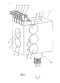
- FIGS Figures 1 to 2b A perspective view of a first embodiment of the device according to the invention for controlling blowing media in a stretch blow molding machine is shown in FIGS Figures 1 to 2b shown.
- the device has a housing block 10 with a first through-bore 11, which is designed to receive a blowing nozzle 100.
- the through hole 11 is cylindrical and extends from the in Fig. 1 shown upper side of the housing block 10 to the underside, not shown.
- control valves 20, 30, 40, 50 and 60 which are in communication with the first through hole 11 and are adapted to selectively connect the received in the through hole 11 blowing nozzle 100 with a respective fluid port.
- the fluid connection the valves 20, 30, 40, 50 with the first through hole 11 will be subsequently with reference to the illustrations in the FIGS. 3 to 5 explained.
- the housing block 10 has a number of valves corresponding number of valve channels 12, 13, 14, 15 and 16, which serve to receive the valves 20, 30, 40, 50 and 60 within the housing block 10.
- the valve channels 12, 13, 14, 15 and 16 are each in fluid communication with the first through hole 11, as for example Fig. 3 is apparent.
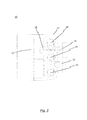
- Fig. 3 It is shown that the first, second, third, fourth, and fifth valve channels 12, 13, 14, 15, 16 are connected to each other via a second through-hole 17, wherein the second through-hole 17 via a connecting channel 18 with the first through hole 11 in connection stands.
- the second through-bore 17 is designed as a collecting tube since it is in fluid communication with the high-pressure side of each valve or valve channel 12, 13, 14, 15, 16 or 20, 30, 40, 50, 60.
- valve channels 12, 13, 14, 15, 16 to the housing block 10 may, for example, the schematic view according to Fig. 5 be removed. It should be noted at this point that in Fig. 5 , in contrast to Fig. 1 , Only 4 valve channels 12, 13, 14 and 15 are shown for reasons of clarity.
- the valve channels 12, 13, 14, 15 are each aligned substantially perpendicular to the first through hole 11.
- the first valve channel 12 is aligned substantially perpendicular to the second valve channel 13 so that the first and second valve (not in Fig. 5 represented) are arranged crosswise.
- third and fourth valve channels 14 and 15, which are also crosswise, ie substantially perpendicular to each other and are arranged to the first through hole 11.
- each second valve channel 12 and 14 or 13 and 15 is aligned in parallel and intersects with the respective other intermediate valve channels 13, 15 and 12, 14th
- valve channels 12, 13, 14, 15 each have a region of large diameter 12a, 13a, 14a, 15a and a region of smaller diameter 12b, 13b, 14b, 15b.
- the valves 20, 30, 40, 50, 60 preferably each have a control side (61st) facing away from the first through-bore 11 Fig. 4 ), which has a diameter which is greater than the diameter of a first through-bore 11 facing high-pressure side (62 Fig. 4 ) of the respective valve (20, 30, 40, 50, 60).
- the "dead air space" can be particularly well reduced by the crossed valves.
- Fig. 4 it is also the Fig. 4 to take the example of the fifth valve 60, that the valves 20, 30, 40, 50, 60, for example, by a biasing spring (not shown) are biased in the idle state with its high pressure side 62 against the valve seat 161 of the respective valve channel 16. Accordingly, the Valves 20, 30, 40, 50 and 60 are closed in their idle state, ie initially there is no pressurization of the compressed air in the first through hole 11 blowing nozzle 100 instead.
- valves 20, 30, 40, 50, 60 by the in the FIGS. 1 and 2 shown pilot valves 81, 82, 83, 84, 85 are activated, a connection between the respective fluid port 122, 132, 142, 152, 162 and located in the first through hole 11 blowing nozzle 100 is produced, since the valve 20, 30, 40 , 50, 60 from his in Fig. 4 shown rest position is shifted to the right, whereby the high-pressure side portion 62 of the valve 60 is lifted from the valve seat 161 and thus produces a fluid connection to the collecting channel 17.
- the respective pilot valve 81 to 85 may be connected to the control side 61 of the valve 60 via a corresponding control air passage.
- the device according to the invention preferably has a connection block 70, which is detachably connected to the housing block 10.
- the terminal block 70 is configured to connect each of the fluid ports 122, 132, 142, 152, 162 (FIG. Fig. 2b ) to be connected to a connecting line 71, 72, 73, 74 and 75, respectively.
- the connecting lines 71, 72, 73, 74, 75 form a fluid connection with a compressed air reservoir or a vent opening.
- the terminal block 70 is preferably attached to the housing block 10 of the device 1 via fasteners (eg, with mounting screws, not shown).
- the connecting lines 71, 72, 73, 74, 75 can be connected in one working step to the fluid connections 122, 132, 142, 152, 162.
- the present invention is not limited to the specific embodiments shown in the drawings. Much more, this results from a combination of the features disclosed herein.
- the present invention is not limited to the number of five valves or valve channels shown in the figures. Rather, any number of valves can be provided. All that matters is that the valves are arranged "crosswise", that is to say alternately, essentially perpendicular to one another.
Abstract
Die vorliegende Erfindung betrifft eine Vorrichtung (1) zum Kontrollieren von Blasmedien in einer Streckblasmaschine zum Erzeugen von Hohlkörpern aus erwärmten Vorformlingen, wobei die Vorrichtung (1) einen Gehäuseblock (10) mit einer ersten Durchgangsbohrung (11) zur Aufnahme mindestens einer Blasdüse (100) aufweist. Darüber hinaus ist ein erstes sowie ein zweites Ventil (20, 30) vorgesehen, welche in Fluidverbindung mit der ersten Durchgangsbohrung (11) stehen und dazu ausgelegt sind, eine in der Durchgangsbohrung (11) aufgenommene Blasdüse (100) wahlweise mit einem Fluidanschluss (122) zu verbinden. Um die Konstruktion der Vorrichtung zu vereinfachen und Leckagen zu verhindern, weisst der Gehäuseblock (10) ferner erste und zweite Ventilkanäle (12, 13) zur Aufnahme des ersten und zweiten Ventils (20, 30) innerhalb des Gehäuseblocks (10) auf, wobei die ersten und zweiten Ventilkanäle (12, 13) in Fluidverbindung mit der ersten Durchgangsbohrung (11) stehen.The present invention relates to a device (1) for controlling blowing media in a stretch blow molding machine for producing hollow bodies from heated preforms, the device (1) comprising a housing block (10) having a first through-bore (11) for receiving at least one blowing nozzle (100). having. In addition, a first and a second valve (20, 30) are provided, which are in fluid communication with the first through hole (11) and are adapted to a in the through hole (11) received blast nozzle (100) optionally with a fluid connection (122 ) connect to. In order to simplify the construction of the device and prevent leaks, the housing block (10) further comprises first and second valve channels (12, 13) for receiving the first and second valves (20, 30) within the housing block (10) first and second valve passages (12, 13) are in fluid communication with the first through-bore (11).
Description
Die vorliegende Erfindung betrifft eine Vorrichtung zum Kontrollieren von Blasmedien in einer Streckblasmaschine zum Erzeugen von Hohlkörpern aus erwärmtem Vorformliegen gemäss dem Oberbegriff des unabhängigen Patentanspruches 1.The present invention relates to a device for controlling blowing media in a stretch blow molding machine for producing hollow bodies from heated preform lying according to the preamble of
Blasmaschinen sind hinreichend aus dem Stand der Technik bekannt. Auf diesen Blasmaschinen werden typischerweise Hohlkörper aus thermoplastischen Kunststoffen mit Volumen zwischen 0,05 und 20 Litern hergestellt. Typische Blasteile sind Flaschen sowie Transport-, Verpackungs- und Lagerbehälter. Für Flaschen und Behälter bis 20 Liter Inhalt wird derzeit vorzugsweise Polyethylenterephthalat (PET) eingesetzt.Blow molding machines are well known in the art. On these blow molding machines, hollow bodies of thermoplastics with a volume of between 0.05 and 20 liters are typically produced. Typical blown parts are bottles as well as transport, packaging and storage containers. For bottles and containers up to 20 liters of content, polyethylene terephthalate (PET) is currently preferably used.
Eine Blasmaschine, welche beispielsweise für PET-Flaschen ausgelegt ist, ist in verschiedenen Varianten (mit und ohne mechanische Reckstange) bekannt. Dabei wird die rohr- oder glockenartige Blasdüse beispielsweise unmittelbar an die Mündung eines Vorformlings oder an einen diesen tragenden Transporter gasdicht angesetzt, um den Vorformling mit Niederdruckblasluft, Hochdruckblasluft oder einer Entlüftung zu verbinden. Die Beaufschlagung des Vorformlings mit Niederdruckblasluft bzw. Hochdruckblasluft wird üblicherweise durch eine Vielzahl von Steuerventilen realisiert, welche mit der Blasdüse in Verbindung stehen.A blow molding machine which is designed, for example, for PET bottles is known in various variants (with and without a mechanical stretching rod). In this case, the tubular or bell-shaped tuyere, for example, attached directly to the mouth of a preform or to this carrying transporter gas-tight, to connect the preform with Niederdruckblasluft, high-pressure blowing air or a vent. The pressurization of the preform with Niederdruckblasluft or Hochdruckblasluft is usually realized by a plurality of control valves, which are in communication with the tuyere.
Die derzeit auf den Markt befindlichen industriellen Streckblasmaschinen erreichen heute Stückzahlen von bis zu 80.000 Flaschen pro Stunde, weshalb es selbstverständlich nötig ist, besonders schnelle Steuerventile für die Beaufschlagung mit Niederdruck bzw. Hochdruckblasluft zu konstruieren. Dabei gilt es den Aufbau und auch den Auslass des Luftdrucks bis 40 bar (Hochdruckblasluft) möglichst schnell zu bewerkstelligen. Ein bekanntes Verfahren hierfür ist den sogenannten "toten Luftraum" möglichst klein zu halten. Unter dem "toten Luftraum" ist die Luftsäule zu verstehen, welche sich zwischen dem Steuerventil und dem zu blasenden Vorformling befindet. Da dieser "tote Luftraum" mit dem in die Flasche geblasenen Luftvolumen entlüftet wird, verursacht er zudem eine Verschwendung der Hochdruckblasluft und damit von Energie.The industrial stretch blow molding machines currently available on the market today reach quantities of up to 80,000 bottles per hour, which is why it is of course necessary to design particularly fast control valves for the application of low pressure or high pressure blowing air. there It is the construction and the outlet of the air pressure up to 40 bar (high-pressure blowing air) to accomplish as quickly as possible. A known method for this is to keep the so-called "dead air space" as small as possible. The term "dead air space" is understood to mean the air column which is located between the control valve and the preform to be blown. As this "dead air space" is vented with the volume of air blown into the bottle, it also causes a waste of high pressure blowing air and thus energy.
In diesem Zusammenhang sei beispielsweise auf die
Die aus dem Stand der Technik bekannte Vorrichtung zum Kontrollieren von Blasmedien in einer Steckblasmaschine hat den Nachteil, dass sich diese nur unter grossem konstruktivem Aufwand produzieren lässt. Insbesondere ist es hierzu nötig, zwei nahezu perfekt aufeinander abgestimmte Gehäuse (Ventilgehäuse, Gehäuseblock der Blasdüse) zu fertigen und diese unter Einhaltung geringster Toleranzen miteinander zu verbinden. Darüber hinaus muss die Schnittstelle zwischen dem Ventilgehäuse und Gehäuseblock bei der bekannten Vorrichtung aufwendig abgedichtet werden, um Leckagen zu vermeiden.The known from the prior art device for controlling blowing media in a slip-blow molding machine has the disadvantage that it can be produced only with great design effort. In particular, it is necessary for this purpose to produce two almost perfectly matched housing (valve housing, housing block of the tuyere) and to connect them with minimum tolerances. In addition, the interface between the valve housing and the housing block must be laboriously sealed in the known device in order to avoid leaks.
Auf Grundlage der oben genannten Problemstellung ist es die Aufgabe der vorliegenden Erfindung, eine Vorrichtung zum Kontrollieren von Blasmedien in einer Streckblasmaschine anzugeben, welche den toten Luftraum zwischen den Steuerventilen und der Blasdüse minimiert und gleichzeitig einen besonders einfachen Aufbau aufweist.Based on the above problem, it is the object of the present invention to provide a device for controlling blowing media in a stretch blow molding machine, which minimizes the dead air space between the control valves and the tuyere and at the same time has a particularly simple construction.
Die oben genannte Aufgabe wird erfindungsgemäss durch eine Vorrichtung gemäss dem unabhängigen Patentanspruch 1 gelöst.The above object is achieved according to the invention by a device according to
Demgemäss weist die erfindungsgemässe Vorrichtung einen Gehäuseblock mit einer ersten Durchgangsbohrung zur Aufnahme mindestens einer Blasdüse auf. Darüber hinaus sind ein erstes sowie ein zweites Ventil vorgesehen, welche jeweils in Fluidverbindung mit der ersten Durchgangsbohrung stehen und dazu ausgelegt sind, eine in der Durchgangsbohrung aufgenommene Blasdüse wahlweise mit einem ersten bzw. zweiten Fluidanschluss zu verbinden. Bei dem Fluidanschluss kann es sich beispielsweise um einen Hochdruck bzw. Niederdruck oder einen Entlüftungsanschluss handeln, welcher vorzugsweise ein gasförmiges Medium wie beispielsweise Luft enthält.Accordingly, the device according to the invention has a housing block with a first through-bore for receiving at least one blowing nozzle. In addition, a first and a second valve are provided which are each in fluid communication with the first through-hole and are adapted to selectively connect a blowing nozzle received in the through-hole with a first or second fluid connection. The fluid connection can be, for example, a high-pressure or low-pressure or a venting connection, which preferably contains a gaseous medium such as, for example, air.
Die erfindungsgemässe Vorrichtung zeichnet sich insbesondere dadurch aus, dass der Gehäuseblock erste und zweite Ventilkanäle zur Aufnahme des ersten und zweiten Ventils innerhalb des Gehäuseblocks aufweist. Dabei stehen die ersten und zweiten Ventilkanäle in Fluidverbindung mit der ersten Durchgangsbohrung, in welcher die Blasdüse aufgenommen ist.The inventive device is characterized in particular by the fact that the housing block has first and second valve channels for receiving the first and second valves within the housing block. In this case, the first and second valve passages are in fluid communication with the first through-bore, in which the blowing nozzle is accommodated.
Die erfindungsgemässe Vorrichtung zum Kontrollieren von Blasmedien in einer Streckblasmaschine weist eine Vielzahl von Vorteilen auf. So sind die Steuerventile, durch die oben erwähnten Ventilkanäle, direkt in den Gehäuseblock der Blasdüse integriert, wodurch sich die erfindungsgemässe Vorrichtung in nur zwei Maschinenaufspannungen herstellen lässt. Insbesondere ist es dadurch nicht notwendig, ein separates Ventilgehäuse sowie einen Gehäuseblock für die Blasdüse herzustellen, wodurch Kosten und Material eingespart werden können. Als Folge dessen ist die erfindungsgemässe Vorrichtung kompakter, wodurch der Platzbedarf an der Streckblasmaschine erheblich verringert wird. Schliesslich sind Dichtungen und Schrauben durch die fehlende Trennstelle zwischen dem Ventilgehäuse und dem Gehäuseblock der Blasdüse nicht mehr notwendig, wodurch die Montage effizienter wird und die Risiken für Leckagen oder Fehler bei der Montage reduziert werden.The inventive device for controlling blowing media in a stretch blow molding machine has a number of advantages. Thus, the control valves, by the above-mentioned valve channels, integrated directly into the housing block of the tuyere, whereby the inventive device can be produced in only two Maschinenspannspannungen. In particular, it is thereby not necessary to produce a separate valve housing and a housing block for the tuyere, whereby costs and material can be saved. As a consequence, the device according to the invention is more compact, which significantly reduces the space requirement on the stretch blow molder. Finally, because of the lack of separation between the valve body and the housing block of the tuyere, gaskets and screws are no longer necessary, making assembly more efficient and reducing the risks of leakage or assembly errors.
Vorteilhafte Weiterbildungen der erfindungsgemässen Vorrichtung sind den Unteransprüchen zu entnehmen.Advantageous developments of the device according to the invention can be found in the subclaims.
So ist es in einer ersten Weiterbildung der erfindungsgemässen Vorrichtung zum Kontrollieren von Blasmedien vorgesehen, dass der erste und zweite Ventilkanal im Wesentlichen senkrecht gegenüber der ersten Durchgangsbohrung ausgerichtet sind. Wie anschliessend näher ausgeführt, wird durch die im Wesentlichen senkrechte Ausrichtung des ersten und zweiten Ventilkanals gegenüber der Durchgangsbohrung erreicht, dass der tote Luftraum auf ein Minimum reduziert wird, da die Ventilkanäle besonders nahe an der Durchgangsbohrung der Blasdüse angeordnet werden können.Thus, it is provided in a first development of the inventive device for controlling blowing media, that the first and second valve channel are aligned substantially perpendicular to the first through hole. As explained in more detail below, it is achieved by the substantially vertical alignment of the first and second valve channels with respect to the through-bore that the dead air space is reduced to a minimum, since the valve channels can be arranged particularly close to the through-bore of the tuyere.
Um den toten Luftraum noch weiter reduzieren zu können, ist es gemäss einem weiteren Aspekt vorgesehen, dass der erste Ventilkanal derart im Wesentlichen senkrecht gegenüber dem zweiten Ventilkanal ausgerichtet ist, dass das erste und zweite Ventil kreuzweise angeordnet sind. In diesem Zusammenhang sei erwähnt, dass die aus dem Stand der Technik bekannten Steuerventile üblicherweise eine Steuerseite aufweisen, welche einen grösseren Durchmesser als die Hochdruckseite aufweist. Dementsprechend können die Ventile, gemäss dieser Ausführungsform, enger aneinander gereiht werden, ohne dass sich die Steuerseiten der Ventile mit dem grösseren Durchmesser berühren. Somit kann die erfindungsgemässe Vorrichtung kompakter gebaut werden, wodurch der entstehende tote Luftraum erheblich reduziert werden kann. Darüber hinaus ist durch die Überkreuzanordnung auch weiterhin eine gute Servicezugänglichkeit zu den Ventilen gegeben.In order to further reduce the dead air space, it is provided according to a further aspect, that the first valve channel is aligned substantially perpendicular to the second valve channel, that the first and second valve are arranged crosswise. In this connection, it should be mentioned that the control valves known from the prior art usually have a control side which has a larger diameter than the high-pressure side. Accordingly, the valves, according to this embodiment, can be strung closer together without touching the control sides of the valves with the larger diameter. Thus, the inventive device can be made more compact, whereby the resulting dead air space can be significantly reduced. Furthermore Due to the crossover arrangement, good service access to the valves continues to be provided.
Unter dem Begriff "im Wesentlichen senkrecht" ist zu verstehen, dass die einzelnen Ventilkanäle nicht zwangsläufig genau unter einem Winkel von 90° zueinander ausgerichtet sein müssen. Vielmehr schliesst diese Formulierung jeden Winkel ein, welcher eine Überkreuzanordnung der Ventile ermöglicht. "Im Wesentlichen senkrecht" bedeutet folglich lediglich, dass die Ventilkanäle alternierend auf unterschiedlichen Seitenflächen des Gehäuseblocks angebracht sind, wobei die niederdruckseitigen (d.h. steuerseitigen) Enden der Ventile jeweils die Längsachse eines gemeinsamen Sammelrohres (= zweite Durchgangsbohrung, siehe unten) schneiden. Konkret betrachtet können die Ventilkanäle bzw. die Ventile demnach bspw. auch unter einem Winkel zwischen 70 und 110° ausgerichtet sein.The term "substantially perpendicular" is to be understood that the individual valve channels do not necessarily have to be aligned exactly at an angle of 90 ° to each other. Rather, this formulation includes any angle that allows a cross arrangement of the valves. "Substantially perpendicular" thus means merely that the valve channels are alternately mounted on different side surfaces of the housing block, with the low pressure (i.e., control) ends of the valves respectively intersecting the longitudinal axis of a common manifold (= second through bore, see below). Seen concretely, the valve channels or the valves can accordingly be aligned, for example, at an angle between 70 and 110 °.
Gemäss einem weiteren Aspekt der erfindungsgemässen Vorrichtung weist der Gehäuseblock ferner eine als Sammelkanal ausgebildete zweite Durchgangsbohrung auf, welche parallel zu der ersten Durchgangsbohrung verläuft und mit dem ersten und zweiten Ventilkanal sowie mit der ersten Durchgangsbohrung in Fluidverbindung steht. Unter dem Begriff "Sammelkanal" ist hierbei eine zu der ersten Durchgangsbohrung parallele Durchgangsbohrung zu verstehen, welche den ersten und zweiten Ventilkanal mit der ersten Durchgangsbohrung verbindet. Mit anderen Worten, die Hochdruckseite der Ventile steht jeweils mit dem Sammelkanal in Verbindung, welcher diese mit der ersten Durchgangsbohrung verbindet. Da vorzugsweise alle Ventile über einen einzigen Sammelkanal mit der ersten Durchgangsbohrung in Fluidverbindung stehen, kann das Ausmass des Gehäuseblocks weiter reduziert werden, wodurch der "tote Luftraum" minimiert wird.According to a further aspect of the device according to the invention, the housing block further has a second through-bore formed as a collecting channel, which extends parallel to the first through-bore and is in fluid communication with the first and second valve channels and with the first through-hole. The term "collecting channel" here is to be understood as a through hole parallel to the first through-hole, which connects the first and second valve channel to the first through-hole. In other words, the high-pressure side of the valves is in each case connected to the collecting channel, which connects them to the first through-bore. Since preferably all the valves are in fluid communication with the first through-hole via a single collection channel, the size of the housing block can be further reduced, thereby minimizing "dead air space".
Neben den ersten und zweiten Ventilen kann die Vorrichtung ferner beliebig viele weitere Ventile aufweisen, welche jeweils in Fluidverbindung mit der ersten Durchgangsbohrung stehen und dazu ausgelegt sind, die in der Durchgangsbohrung aufgenommene Blasdüse wahlweise mit beliebig vielen weiteren Fluidanschlüssen zu verbinden. Äquivalent zu den ersten und zweiten Ventilen ist es auch hierbei vorgesehen, dass der Gehäuseblock ferner beliebig viele weitere Ventilkanäle zur Aufnahme der entsprechenden Ventile innerhalb des Gehäuseblocks aufweist. Hierbei stehen selbstverständlich auch die entsprechenden Ventilkanäle in Fluidverbindung mit der ersten Durchgangsbohrung. Im Einzelnen ist es gemäss einer bevorzugten Ausführungsform vorgesehen, dass die Vorrichtung ferner dritte, vierte und fünfte Ventile und weitere aufweist, welche jeweils in Fluidverbindung mit der ersten Durchgangsbohrung stehen, wobei der Gehäuseblock folglich dritte, vierte und fünfte und weitere Ventilkanäle zur Aufnahme dieser Ventile aufweist. Demgemäss steht ausser Frage, dass durch das Vorsehen weiterer Ventile die Steuermöglichkeiten der Blasmaschine erheblich verbessert werden. So kann beispielsweise neben einer Entlüftung auch ein Ventil zum Recycling der bereits verwendeten Hochdruckblasluft vorgesehen sein. Auch ist es hierdurch denkbar, eine Vielzahl verschiedener Blasdrücke bereitzustellen.In addition to the first and second valves, the device further comprise any number of other valves, which are each in fluid communication with the first through hole and are adapted to connect the recorded in the through hole blower optionally with any number of other fluid connections. Equivalent to the first and second valves, it is also provided here that the housing block further comprises any number of further valve channels for receiving the corresponding valves within the housing block. Of course, the corresponding valve channels are also in fluid communication with the first through-bore. In particular, according to a preferred embodiment, it is provided that the device further comprises third, fourth and fifth valves and others which are respectively in fluid communication with the first through-hole, the housing block consequently having third, fourth and fifth and further valve channels for receiving these valves having. Accordingly, there is no question that the control options of the blow molding machine are significantly improved by the provision of additional valves. Thus, for example, in addition to a vent, a valve for recycling the already used high-pressure blowing air can be provided. It is also conceivable to provide a variety of different blowing pressures.
Gemäss einer bevorzugten Ausführungsform ist dabei vorgesehen, dass mindestens ein Niederdruckventil, ein Hochdruck-Ventil sowie mindestens ein Entlüftungs-Ventil vorgesehen sind. Darüber hinaus kann, ein Recycling-Ventil vorgesehen sein. Weitere Ventile können dazu ausgebildet sein, Blasdrücke bereitzustellen, welche zwischen dem Niederdruck und dem Hochdruck liegen.According to a preferred embodiment, it is provided that at least one low-pressure valve, a high-pressure valve and at least one venting valve are provided. In addition, a recycling valve may be provided. Other valves may be configured to provide blowing pressures that are between the low pressure and the high pressure.
Wie bereits in Bezug auf den ersten und zweiten Ventilkanal erwähnt, ist es von Vorteil, diese kreuzweise anzuordnen. Dementsprechend ist es gemäss einer weiteren Umsetzung vorgesehen, dass die weiteren Ventilkanäle, bspw. der dritte, vierte und fünfte Ventilkanal, im Wesentlichen senkrecht gegenüber der ersten Durchgangsbohrung ausgerichtet sind, wobei die ersten, dritten fünften und ggf. weiteren ungeradzahligen Ventilkanäle jeweils derart senkrecht gegenüber den zweiten vierten und ggf. weiteren geradzahligen Ventilkanälen ausgerichtet sind, sodass die Ventile kreuzweise angeordnet sind. Dementsprechend wird der "tote Luftraum" effizient reduziert.As already mentioned with regard to the first and second valve channels, it is advantageous to arrange them crosswise. Accordingly, it is provided according to a further implementation, that the further valve channels, for example. The third, fourth and fifth valve channel, are aligned substantially perpendicular to the first through hole, wherein the first, third fifth and possibly further odd-numbered valve channels are each aligned so perpendicular to the second fourth and possibly further even-numbered valve channels, so that the valves are arranged crosswise. Accordingly, the "dead air space" is efficiently reduced.
Bei der oben erwähnten kreuzweisen Anordnung der Ventile ist es bevorzugt, den Gehäuseblock im Wesentlichen rechteckig auszubilden, wobei der erste, dritte, fünfte und ggf. weitere ungeradzahlige Ventilkanäle jeweils auf einer ersten Seitenfläche des Gehäuseblocks angeordnet sind, und wobei der zweite und vierte und ggf. weitere geradzahlige Ventilkanäle jeweils auf einer zweiten, zur ersten Seitenfläche senkrechten Seitenfläche des Gehäuseblocks angeordnet sind. Mit anderen Worten, jeder zweite Ventilkanal und somit jedes zweite Ventil ist parallel entlang des Sammelkanals angeordnet, wodurch sich alternierend eine kreuzweise Anordnung der Ventile ergibt. Diese Anordnung ist besonders vorteilhalft in Bezug auf die Reduzierung des toten Luftraums. Dies ist insbesondere dann der Fall, wenn die Ventile gemäss eines weiteren Aspekts, jeweils eine von der ersten Durchgangsbohrung abgewandte Steuerseite aufweisen, welche einen Durchmesser aufweist, der grösser ist als der Durchmesser einer der ersten Durchgangsbohrungen zugewandten Hochdruckseite des jeweiligen Ventils. Anders ausgedrückt, lassen sich die Ventile auf diese Weise als Keile beschreiben, welche ineinander geschoben werden, um somit eine möglichst dichte Anordnung zu gewährleisten. Hierdurch können die gesamten Ventile besonders nahe an die erste Durchgangsbohrung heran geführt werden, wodurch sich der Tote Luftraum verringert und folglich die Schaltzeiten der Blasmaschine reduziert werden können.In the above-mentioned crosswise arrangement of the valves, it is preferable to form the housing block substantially rectangular, wherein the first, third, fifth and possibly further odd-numbered valve channels are each arranged on a first side surface of the housing block, and wherein the second and fourth and optionally Further even-numbered valve channels are each arranged on a second, perpendicular to the first side surface side surface of the housing block. In other words, every second valve channel and thus every second valve is arranged in parallel along the collecting channel, which results in a crosswise arrangement of the valves alternately. This arrangement is particularly advantageous in terms of reducing the dead air space. This is the case in particular when, according to a further aspect, the valves each have a control side remote from the first through-bore, which has a diameter which is greater than the diameter of a high-pressure side of the respective valve facing the first through-bores. In other words, the valves can be described in this way as wedges, which are pushed into each other, thus ensuring a dense arrangement possible. As a result, the entire valves can be zoomed particularly close to the first through hole, which reduces the dead air space and consequently the switching times of the blow molding machine can be reduced.
Gemäss einer weiteren Ausführungsform kann die Vorrichtung ferner einen Anschlussblock aufweisen, welcher lösbar mit dem Gehäuseblock verbunden und dazu ausgebildet ist, jeden der Fluidanschlüsse mit einer Anschlussleitung zu verbinden. Der Anschlussblock kann beispielsweise durch Befestigungselemente (z. B. Schrauben) an dem Gehäuseblock angebracht werden, um diesen mit einer Luftdruckwelle bzw. mit einer Entlüftungsöffnung zu verbinden. Insbesondere können durch den Anschlussblock alle Fluidanschlüsse gleichzeitig mit ihrer jeweiligen Anschlussleitung verbunden werden, wodurch die Montagezeit erheblich reduziert wird.According to a further embodiment, the device may further comprise a connection block, which is detachably connected to the housing block and adapted to connect each of the fluid connections to a connecting line. The terminal block may be attached to the housing block by fasteners (eg, screws), for example, to connect it to an air pressure shaft or to a vent opening. In particular, all the fluid connections can be connected simultaneously with their respective connection line through the terminal block, whereby the assembly time is significantly reduced.
Gemäss einem weiteren Aspekt kann die Vorrichtung für jedes Steuerventil mindestens ein Pilotventil aufweisen, welches lösbar mit dem Gehäuseblock verbunden und dazu ausgelegt ist, die im Gehäuseblock befindlichen Ventile anzusteuern. Die Pilotventile sind vorzugsweise als Magnetventile ausgebildet, wodurch die Schaltzeiten der erfindungsgemässen Vorrichtung optimiert werden können. Die Pilotventile können beispielsweise über Schraubverbindungen an der Aussenseite des Gehäuseblocks befestigt werden. In diesem Zusammenhang sei darauf hingewiesen, dass der Gehäuseblock dementsprechend weitere Verbindungskanäle aufweist, welche die Pilotventile mit den am Gehäuseblock befindlichen Ventilen verbindet.According to a further aspect, the device may comprise for each control valve at least one pilot valve, which is detachably connected to the housing block and adapted to control the valves located in the housing block. The pilot valves are preferably designed as solenoid valves, whereby the switching times of the inventive device can be optimized. The pilot valves can be fastened for example via screw connections on the outside of the housing block. In this context, it should be noted that the housing block accordingly has further connection channels, which connects the pilot valves with the valves located on the housing block.
Im Folgenden wird die erfindungsgemässe Vorrichtung mit Bezug auf die in den Figuren dargestellten Ausführungsformen näher erläutert.In the following, the device according to the invention will be explained in more detail with reference to the embodiments shown in the figures.
Dabei zeigen:
- Fig. 1
- eine perspektivische Frontansicht einer ersten Ausführungsform der erfindungsgemässen Vorrichtung zum Kontrollieren von Blasmedien in einer Streckblasmaschine;
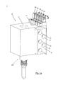
- Fig. 2a
- eine perspektivische Rückansicht der in
Fig. 1 dargestellten Ausführungsform mit Anschlussblock; - Fig. 2b
- eine perspektivische Rückansicht der in
Fig. 1 dargestellten Ausführungsform ohne Anschlussblock; - Fig. 3
- eine Querschnittansicht durch den Gehäuseblock der in
Fig. 1 dargestellten ersten Ausführungsform; - Fig. 4
- einen Halbschnitt durch die in
Fig. 1 dargestellte erste Ausführungsform; und - Fig. 5
- eine schematische Perspektivansicht eines Gehäuse-blocks mit überkreuzt angeordneten Ventilkanälen.
- Fig. 1
- a front perspective view of a first embodiment of the inventive device for controlling blowing media in a stretch blow molding machine;
- Fig. 2a
- a perspective rear view of in
Fig. 1 illustrated embodiment with terminal block; - Fig. 2b
- a perspective rear view of in
Fig. 1 illustrated embodiment without terminal block; - Fig. 3
- a cross-sectional view through the housing block of in
Fig. 1 illustrated first embodiment; - Fig. 4
- a half cut through the in
Fig. 1 illustrated first embodiment; and - Fig. 5
- a schematic perspective view of a housing block with crossed valve channels arranged.
In der folgenden detaillierten Figurenbeschreibung sind gleiche oder gleichwirkende Bauteile mit gleichen Bezugszeichen versehen.In the following detailed description of the figures, identical or equivalent components are provided with the same reference numerals.
Eine perspektivische Ansicht einer ersten Ausführungsform der erfindungsgemässen Vorrichtung zum Kontrollieren von Blasmedien in einer Streckblasmaschine ist in den
Ebenfalls im Gehäuseblock 10 befinden sich Steuerventile 20, 30, 40, 50 und 60, welche in Verbindung mit der ersten Durchgangsbohrung 11 stehen und dazu ausgelegt sind, die in der Durchgangsbohrung 11 aufgenommene Blasdüse 100 wahlweise mit einem jeweiligen Fluidanschluss zu verbinden. Die Fluid-verbindung der Ventile 20, 30, 40, 50 mit der ersten Durchgangsbohrung 11 wird anschliessend mit Bezug auf die Darstellungen in den
Der Gehäuseblock 10 weist eine der Anzahl an Ventilen entsprechende Anzahl an Ventilkanälen 12, 13, 14, 15 und 16 auf, welche zur Aufnahme der Ventile 20, 30, 40, 50 bzw. 60 innerhalb des Gehäuseblocks 10 dienen. Dabei stehen die Ventilkanäle 12, 13, 14, 15 und 16 jeweils in Fluidverbindung mit der ersten Durchgangsbohrung 11, wie dies beispielsweise aus
In
Die Anordnung der Ventilkanäle 12, 13, 14, 15, 16 zum Gehäuseblock 10 kann beispielsweise der schematischen Ansicht gemäss
Wie es der
Es ist ferner aus
Es ist ferner der
Erst wenn die Ventile 20, 30, 40, 50, 60 durch die in den
Zwar ist dies nicht explizit in
Zurückkommend auf
Die vorliegende Erfindung ist nicht auf die in den Darstellungen gezeigten speziellen Ausführungsformen beschränkt. Viel mehr ergibt sich diese aus einer Kombination der hierin offenbarten Merkmale. Beispielsweise sei erwähnt, dass die vorliegende nicht auf die in den Figuren dargestellte Anzahl von fünf Ventilen bzw. Ventilkanälen beschränkt ist. Vielmehr kann eine beliebige Anzahl an Ventilen vorgesehen sein. Entscheidend ist lediglich, dass die Ventile "überkreuz" das heisst alternierend, im Wesentlichen senkrecht zueinander angeordnet sind.The present invention is not limited to the specific embodiments shown in the drawings. Much more, this results from a combination of the features disclosed herein. For example, it should be noted that the present invention is not limited to the number of five valves or valve channels shown in the figures. Rather, any number of valves can be provided. All that matters is that the valves are arranged "crosswise", that is to say alternately, essentially perpendicular to one another.
Claims (15)
wobei der erste und der zweite Ventilkanal (12, 13) im Wesentlichen senkrecht gegenüber der ersten Durchgangsbohrung (11) ausgerichtet sind.Device (1) according to claim 1,
wherein the first and second valve channels (12, 13) are aligned substantially perpendicular to the first through hole (11).
wobei der erste Ventilkanal (12) im Wesentlichen senkrecht gegenüber dem zweiten Ventilkanal (13) ausgerichtet ist, sodass das erste und zweite Ventil (20, 30) kreuzweise angeordnet sind.Device (1) according to claim 2,
wherein the first valve channel (12) is aligned substantially perpendicular to the second valve channel (13) is such that the first and second valves (20, 30) are arranged crosswise.
wobei der Gehäuseblock (10) ferner eine als Sammelkanal ausgebildete zweite Durchgangsbohrung (17) aufweist, welche im Wesentlichen parallel zu der ersten Durchgangsbohrung (11) verläuft und mit dem ersten und zweiten Ventilkanal (12, 13) sowie mit der ersten Durchgangsbohrung (11) in Fluidverbindung steht.Device (1) according to one of the preceding claims,
wherein the housing block (10) further comprises a second through-bore (17) designed as a collecting channel, which runs essentially parallel to the first through-bore (11) and with the first and second valve channels (12, 13) and with the first through-hole (11). is in fluid communication.
wobei die Vorrichtung (1) ferner ein drittes, viertes und fünftes Ventil (40, 50, 60) aufweist, welche jeweils in Fluidverbindung mit der ersten Durchgangsbohrung (11) stehen und dazu ausgelegt sind, die in der Durchgangsbohrung (11) aufgenommene Blasdüse (100) wahlweise mit einem dritten, vierten oder fünften Fluidanschluss zu verbinden,
und wobei der Gehäuseblock (10) ferner dritte, vierte und fünfte Ventilkanäle (14, 15, 16) zur Aufnahme des dritten, vierten und fünften Ventils (40, 50, 60) innerhalb des Gehäuseblocks (10) aufweist, wobei die dritten, vierten und fünften Ventilkanäle (14, 15, 16) in Fluidverbindung mit der ersten Durchgangsbohrung (11) stehen.Device (1) according to one of the preceding claims,
the apparatus (1) further comprising third, fourth and fifth valves (40, 50, 60) each in fluid communication with the first through-bore (11) and adapted to receive the blast nozzle (11) received in the through-bore (11). 100) optionally connect to a third, fourth or fifth fluid port,
and wherein the housing block (10) further includes third, fourth and fifth valve channels (14, 15, 16) for receiving the third, fourth and fifth valves (40, 50, 60) within the housing block (10), the third, fourth and fifth valve passages (14, 15, 16) are in fluid communication with the first through-bore (11).
wobei mindestens eines der Ventile (20, 30, 40, 50, 60) als Niederdruck-Ventil, mindestens eines der Ventile (20, 30, 40, 50, 60) als Hochdruck-Ventil und mindestens eines der Ventile (20, 30, 40, 50, 60) als Entlüftungs-Ventil ausgebildet ist.Device (1) according to claim 5,
wherein at least one of the valves (20, 30, 40, 50, 60) as a low-pressure valve, at least one of the valves (20, 30, 40, 50, 60) as a high-pressure valve and at least one of the valves (20, 30, 40, 50, 60) is designed as a vent valve.
wobei mindestens eines der Ventile (20, 30, 40, 50, 60) als Recycle-Ventil ausgebildet ist.Device (1) according to claim 6,
wherein at least one of the valves (20, 30, 40, 50, 60) is designed as a recycle valve.
wobei der dritte, vierte und fünfte Ventilkanal (14, 15, 16) im Wesentlichen senkrecht gegenüber der ersten Durchgangsbohrung (11) ausgerichtet sind,
und wobei der erste, dritte und fünfte Ventilkanal (12, 14, 16) jeweils derart im Wesentlichen senkrecht gegenüber dem zweiten und vierten Ventilkanal (13, 15) ausgerichtet sind, sodass die Ventile (20, 30, 40, 50, 60) kreuzweise angeordnet sind.Device (1) according to one of claims 5 to 7,
wherein the third, fourth and fifth valve channels (14, 15, 16) are aligned substantially perpendicular to the first through-hole (11),
and wherein the first, third and fifth valve passages (12, 14, 16) are each aligned substantially perpendicularly with respect to the second and fourth valve passages (13, 15) so that the valves (20, 30, 40, 50, 60) are crosswise are arranged.
wobei der Gehäuseblock (10) im Wesentlichen rechteckig ausgebildet ist und der erste, dritte und fünfte Ventilkanal (12, 14, 16) jeweils auf einer ersten Seitenfläche des Gehäuseblocks (10) angeordnet sind.Device (1) according to claim 8,
wherein the housing block (10) is formed substantially rectangular and the first, third and fifth valve channel (12, 14, 16) respectively on a first side surface of the housing block (10) are arranged.
wobei der zweite und vierte Ventilkanal (13, 15) jeweils auf einer zweiten, zur ersten Seitenfläche senkrechten Seitenfläche des Gehäuseblocks (10) angeordnet sind.Device (1) according to claim 9,
wherein the second and fourth valve channels (13, 15) are each arranged on a second, perpendicular to the first side surface side surface of the housing block (10).
wobei die Ventile (20, 30, 40, 50, 60) jeweils eine von der ersten Durchgangsbohrung (11) abgewandte, Steuerseite (61) aufweisen, welche einen Durchmesser aufweist, der grösser ist als der Durchmesser einer der ersten Durchgangsbohrung (11) zugewandten Hochdruckseite (62) des jeweiligen Ventils (20, 30, 40, 50, 60).Device (1) according to one of the preceding claims,
wherein the valves (20, 30, 40, 50, 60) each have a control side (61) facing away from the first through-bore (11), which has a diameter which is greater than the diameter of one of the first through-bore (11) facing High pressure side (62) of the respective valve (20, 30, 40, 50, 60).
wobei die Vorrichtung (1) ferner einen Anschlussblock (70) aufweist, welcher lösbar mit dem Gehäuseblock (10) verbunden und dazu ausgebildet ist, jeden der Fluidanschlüsse (122) mit einer Anschlussleitung (71, 72, 73, 74, 75) zu verbinden.Device (1) according to one of the preceding claims,
the device (1) further comprising a terminal block (70) releasably connected to the housing block (10) and adapted to connect each of the fluid ports (122) to a lead (71, 72, 73, 74, 75) ,
wobei die Vorrichtung (1) für jedes Ventil (20, 30, 40, 50, 60) mindestens ein Pilotventil (81, 82, 83, 84, 85) aufweist, welches lösbar mit dem Gehäuseblock (10) verbunden und dazu ausgelegt ist, die im Gehäuseblock (10) befindlichen Ventile (20, 30, 40, 50, 60) anzusteuern.Device (1) according to one of the preceding claims,
the device (1) having for each valve (20, 30, 40, 50, 60) at least one pilot valve (81, 82, 83, 84, 85) detachably connected to the housing block (10) and adapted to to control the valves (20, 30, 40, 50, 60) located in the housing block (10).
wobei die Pilotventile (81, 82, 83, 84, 85) als Pneumatikventile ausgebildet sind.Device (1) according to claim 13,
wherein the pilot valves (81, 82, 83, 84, 85) are designed as pneumatic valves.
Priority Applications (3)
| Application Number | Priority Date | Filing Date | Title |
|---|---|---|---|
| EP13405100.2A EP2837486B1 (en) | 2013-08-14 | 2013-08-14 | Device for controlling blowing media in the stretch blowing machine |
| CN201410395234.0A CN104369358B (en) | 2013-08-14 | 2014-08-12 | Device for the air blowing medium in restrained stretching air feeder |
| US14/458,715 US9221208B2 (en) | 2013-08-14 | 2014-08-13 | Device for controlling blowing mediums in a stretch blow moulding machine |
Applications Claiming Priority (1)
| Application Number | Priority Date | Filing Date | Title |
|---|---|---|---|
| EP13405100.2A EP2837486B1 (en) | 2013-08-14 | 2013-08-14 | Device for controlling blowing media in the stretch blowing machine |
Publications (2)
| Publication Number | Publication Date |
|---|---|
| EP2837486A1 true EP2837486A1 (en) | 2015-02-18 |
| EP2837486B1 EP2837486B1 (en) | 2018-09-19 |
Family
ID=49034022
Family Applications (1)
| Application Number | Title | Priority Date | Filing Date |
|---|---|---|---|
| EP13405100.2A Active EP2837486B1 (en) | 2013-08-14 | 2013-08-14 | Device for controlling blowing media in the stretch blowing machine |
Country Status (3)
| Country | Link |
|---|---|
| US (1) | US9221208B2 (en) |
| EP (1) | EP2837486B1 (en) |
| CN (1) | CN104369358B (en) |
Cited By (2)
| Publication number | Priority date | Publication date | Assignee | Title |
|---|---|---|---|---|
| CN109296781A (en) * | 2018-10-30 | 2019-02-01 | 安沃驰气动设备(常州)有限公司 | One kind is novel to blow bottle combined valve |
| EP3711926A1 (en) | 2019-03-22 | 2020-09-23 | Eugen Seitz AG | Blow valve device of a blowing device |
Families Citing this family (5)
| Publication number | Priority date | Publication date | Assignee | Title |
|---|---|---|---|---|
| DE102017109112A1 (en) * | 2017-04-27 | 2018-10-31 | Norgren Ag | Device for compressed air control |
| CN109296784A (en) * | 2018-10-30 | 2019-02-01 | 安沃驰气动设备(常州)有限公司 | One kind blowing bottle combined valve |
| CN116985383A (en) | 2019-03-22 | 2023-11-03 | 欧根赛驰股份公司 | Blow valve device of blow molding device |
| DE102019110074B4 (en) * | 2019-04-16 | 2022-01-13 | Bürkert Werke GmbH & Co. KG | Dosing unit for dosing fluids, dosing station, dosing tip for a dosing unit and method for dosing a fluid |
| IT202100027404A1 (en) * | 2021-10-26 | 2023-04-26 | Smi Spa | VALVE ASSEMBLY FOR BLOWING OR STRETCH-BLOWING BOTTLES MADE OF POLYMER MATERIAL |
Citations (5)
| Publication number | Priority date | Publication date | Assignee | Title |
|---|---|---|---|---|
| DE20305232U1 (en) * | 2003-04-01 | 2003-05-28 | Festo Ag & Co | Valve block has HP and LP valves both connected on outlet side to common working channel and each with switchable valve component by which connection between respective valve inlets and outlets is selectively closed or opened |
| US7927093B2 (en) | 2005-08-12 | 2011-04-19 | Sidel Participations | Fluid flow control assembly for a container blowing machine and machine comprising one such assembly |
| US20120199779A1 (en) * | 2009-10-09 | 2012-08-09 | Norgren Gmbh | Valve block assembly for a blow molding system |
| US20120201918A1 (en) * | 2009-10-09 | 2012-08-09 | Christian Elbs | Blow molding valve for a blow molding valve block |
| US20120241012A1 (en) * | 2009-12-18 | 2012-09-27 | Norgren Gmbh | Multiple-stage valve system |
Family Cites Families (4)
| Publication number | Priority date | Publication date | Assignee | Title |
|---|---|---|---|---|
| DE20018500U1 (en) * | 2000-10-28 | 2001-12-13 | Krones Ag | Blowing machine |
| FR2872082B1 (en) * | 2004-06-23 | 2006-10-06 | Sidel Sas | INSTALLATION FOR BLOWING CONTAINERS IN THERMOPLASTIC MATERIAL |
| DE102004041973B3 (en) * | 2004-08-31 | 2006-01-19 | Krones Ag | Air recycling in the blow molding process |
| DE102009020738A1 (en) * | 2009-05-11 | 2010-11-25 | Krones Ag | Apparatus for blow molding plastic preforms with reduced dead volume |
-
2013
- 2013-08-14 EP EP13405100.2A patent/EP2837486B1/en active Active
-
2014
- 2014-08-12 CN CN201410395234.0A patent/CN104369358B/en active Active
- 2014-08-13 US US14/458,715 patent/US9221208B2/en active Active
Patent Citations (5)
| Publication number | Priority date | Publication date | Assignee | Title |
|---|---|---|---|---|
| DE20305232U1 (en) * | 2003-04-01 | 2003-05-28 | Festo Ag & Co | Valve block has HP and LP valves both connected on outlet side to common working channel and each with switchable valve component by which connection between respective valve inlets and outlets is selectively closed or opened |
| US7927093B2 (en) | 2005-08-12 | 2011-04-19 | Sidel Participations | Fluid flow control assembly for a container blowing machine and machine comprising one such assembly |
| US20120199779A1 (en) * | 2009-10-09 | 2012-08-09 | Norgren Gmbh | Valve block assembly for a blow molding system |
| US20120201918A1 (en) * | 2009-10-09 | 2012-08-09 | Christian Elbs | Blow molding valve for a blow molding valve block |
| US20120241012A1 (en) * | 2009-12-18 | 2012-09-27 | Norgren Gmbh | Multiple-stage valve system |
Cited By (3)
| Publication number | Priority date | Publication date | Assignee | Title |
|---|---|---|---|---|
| CN109296781A (en) * | 2018-10-30 | 2019-02-01 | 安沃驰气动设备(常州)有限公司 | One kind is novel to blow bottle combined valve |
| CN109296781B (en) * | 2018-10-30 | 2023-09-22 | 世格流体控制(上海)有限公司 | Novel bottle blowing combined valve |
| EP3711926A1 (en) | 2019-03-22 | 2020-09-23 | Eugen Seitz AG | Blow valve device of a blowing device |
Also Published As
| Publication number | Publication date |
|---|---|
| EP2837486B1 (en) | 2018-09-19 |
| US20150050381A1 (en) | 2015-02-19 |
| CN104369358A (en) | 2015-02-25 |
| US9221208B2 (en) | 2015-12-29 |
| CN104369358B (en) | 2018-03-09 |
Similar Documents
| Publication | Publication Date | Title |
|---|---|---|
| EP2837486B1 (en) | Device for controlling blowing media in the stretch blowing machine | |
| EP2338671B1 (en) | Device for inserting air and/or sealant into a tyre | |
| DE102007059651B4 (en) | Sampler for high performance liquid chromatography | |
| DE10206502C1 (en) | Pressurized gas tank with several tanks | |
| DE102015110073B4 (en) | Bellows seal and working head of a device or machine for producing and / or treating containers with such a bellows seal | |
| DE102015101992B4 (en) | solenoid valve | |
| DE102011017739A1 (en) | Method and device for enriching a liquid with gas | |
| EP4061624A1 (en) | Apparatus for transporting compressed air and/or sealant in a vehicle tire and portable/transportable system for sealing and inflating vehicle tires | |
| EP2956242B1 (en) | Coating agent pump and cleaning method for a coating agent pump | |
| DE10348278A1 (en) | Method and device for treating a running thread with a gaseous and vaporous treatment medium | |
| DD283074A5 (en) | PRESSURE CHANGE ADSORPTION SYSTEM FOR DISCONNECTING GAS MIXTURES | |
| DE102016106909A1 (en) | Electropneumatic valve group | |
| EP0515449B1 (en) | Device for cutting and cleaning objects using a water/abrasive mixture at high pressure | |
| DE102013014264A1 (en) | Closing unit for an injection molding machine | |
| EP2728226B1 (en) | Vacuum valve | |
| DE19827883A1 (en) | Unit for a compressed air system | |
| EP0743485B1 (en) | Filling device for the gas bottles of a gas-operated omnibus | |
| WO2020094300A1 (en) | Distributor device, system, and sealing and application methods | |
| DE202017102605U1 (en) | valve combination | |
| DE102008005764A1 (en) | Clamping device for flexible drives in the control drive of a motor vehicle | |
| DE102009038811B3 (en) | Machine, in particular container handling machine | |
| DE102011050973B4 (en) | Vacuum valve, tool with such a vacuum valve and method for such a tool | |
| DE19540918C2 (en) | Gas compression and distribution facility | |
| EP2392409B1 (en) | Device for applying glue to areas of paper or plastic sheets or paper or plastic sheet sections and method for producing same | |
| DE102006010086B4 (en) | Mounting plate for medium-flow coaxial valves, plate system and associated coaxial valve |
Legal Events
| Date | Code | Title | Description |
|---|---|---|---|
| 17P | Request for examination filed |
Effective date: 20130814 |
|
| AK | Designated contracting states |
Kind code of ref document: A1 Designated state(s): AL AT BE BG CH CY CZ DE DK EE ES FI FR GB GR HR HU IE IS IT LI LT LU LV MC MK MT NL NO PL PT RO RS SE SI SK SM TR |
|
| AX | Request for extension of the european patent |
Extension state: BA ME |
|
| PUAI | Public reference made under article 153(3) epc to a published international application that has entered the european phase |
Free format text: ORIGINAL CODE: 0009012 |
|
| R17P | Request for examination filed (corrected) |
Effective date: 20150818 |
|
| RBV | Designated contracting states (corrected) |
Designated state(s): AL AT BE BG CH CY CZ DE DK EE ES FI FR GB GR HR HU IE IS IT LI LT LU LV MC MK MT NL NO PL PT RO RS SE SI SK SM TR |
|
| GRAP | Despatch of communication of intention to grant a patent |
Free format text: ORIGINAL CODE: EPIDOSNIGR1 |
|
| STAA | Information on the status of an ep patent application or granted ep patent |
Free format text: STATUS: GRANT OF PATENT IS INTENDED |
|
| RIC1 | Information provided on ipc code assigned before grant |
Ipc: F16K 27/00 20060101ALN20180306BHEP Ipc: B29C 49/46 20060101ALI20180306BHEP Ipc: B29C 49/42 20060101AFI20180306BHEP Ipc: B29K 67/00 20060101ALN20180306BHEP |
|
| INTG | Intention to grant announced |
Effective date: 20180322 |
|
| RIC1 | Information provided on ipc code assigned before grant |
Ipc: B29C 49/42 20060101AFI20180313BHEP Ipc: B29K 67/00 20060101ALN20180313BHEP Ipc: F16K 27/00 20060101ALN20180313BHEP Ipc: B29C 49/46 20060101ALI20180313BHEP |
|
| GRAS | Grant fee paid |
Free format text: ORIGINAL CODE: EPIDOSNIGR3 |
|
| GRAA | (expected) grant |
Free format text: ORIGINAL CODE: 0009210 |
|
| STAA | Information on the status of an ep patent application or granted ep patent |
Free format text: STATUS: THE PATENT HAS BEEN GRANTED |
|
| AK | Designated contracting states |
Kind code of ref document: B1 Designated state(s): AL AT BE BG CH CY CZ DE DK EE ES FI FR GB GR HR HU IE IS IT LI LT LU LV MC MK MT NL NO PL PT RO RS SE SI SK SM TR |
|
| REG | Reference to a national code |
Ref country code: GB Ref legal event code: FG4D Free format text: NOT ENGLISH |
|
| REG | Reference to a national code |
Ref country code: CH Ref legal event code: EP Ref country code: CH Ref legal event code: NV Representative=s name: ISLER AND PEDRAZZINI AG, CH |
|
| REG | Reference to a national code |
Ref country code: AT Ref legal event code: REF Ref document number: 1042741 Country of ref document: AT Kind code of ref document: T Effective date: 20181015 |
|
| REG | Reference to a national code |
Ref country code: IE Ref legal event code: FG4D Free format text: LANGUAGE OF EP DOCUMENT: GERMAN |
|
| REG | Reference to a national code |
Ref country code: DE Ref legal event code: R096 Ref document number: 502013011109 Country of ref document: DE |
|
| REG | Reference to a national code |
Ref country code: NL Ref legal event code: MP Effective date: 20180919 |
|
| PG25 | Lapsed in a contracting state [announced via postgrant information from national office to epo] |
Ref country code: LT Free format text: LAPSE BECAUSE OF FAILURE TO SUBMIT A TRANSLATION OF THE DESCRIPTION OR TO PAY THE FEE WITHIN THE PRESCRIBED TIME-LIMIT Effective date: 20180919 Ref country code: FI Free format text: LAPSE BECAUSE OF FAILURE TO SUBMIT A TRANSLATION OF THE DESCRIPTION OR TO PAY THE FEE WITHIN THE PRESCRIBED TIME-LIMIT Effective date: 20180919 Ref country code: GR Free format text: LAPSE BECAUSE OF FAILURE TO SUBMIT A TRANSLATION OF THE DESCRIPTION OR TO PAY THE FEE WITHIN THE PRESCRIBED TIME-LIMIT Effective date: 20181220 Ref country code: RS Free format text: LAPSE BECAUSE OF FAILURE TO SUBMIT A TRANSLATION OF THE DESCRIPTION OR TO PAY THE FEE WITHIN THE PRESCRIBED TIME-LIMIT Effective date: 20180919 Ref country code: BG Free format text: LAPSE BECAUSE OF FAILURE TO SUBMIT A TRANSLATION OF THE DESCRIPTION OR TO PAY THE FEE WITHIN THE PRESCRIBED TIME-LIMIT Effective date: 20181219 Ref country code: NO Free format text: LAPSE BECAUSE OF FAILURE TO SUBMIT A TRANSLATION OF THE DESCRIPTION OR TO PAY THE FEE WITHIN THE PRESCRIBED TIME-LIMIT Effective date: 20181219 Ref country code: SE Free format text: LAPSE BECAUSE OF FAILURE TO SUBMIT A TRANSLATION OF THE DESCRIPTION OR TO PAY THE FEE WITHIN THE PRESCRIBED TIME-LIMIT Effective date: 20180919 |
|
| REG | Reference to a national code |
Ref country code: LT Ref legal event code: MG4D |
|
| PG25 | Lapsed in a contracting state [announced via postgrant information from national office to epo] |
Ref country code: HR Free format text: LAPSE BECAUSE OF FAILURE TO SUBMIT A TRANSLATION OF THE DESCRIPTION OR TO PAY THE FEE WITHIN THE PRESCRIBED TIME-LIMIT Effective date: 20180919 Ref country code: LV Free format text: LAPSE BECAUSE OF FAILURE TO SUBMIT A TRANSLATION OF THE DESCRIPTION OR TO PAY THE FEE WITHIN THE PRESCRIBED TIME-LIMIT Effective date: 20180919 Ref country code: AL Free format text: LAPSE BECAUSE OF FAILURE TO SUBMIT A TRANSLATION OF THE DESCRIPTION OR TO PAY THE FEE WITHIN THE PRESCRIBED TIME-LIMIT Effective date: 20180919 |
|
| PG25 | Lapsed in a contracting state [announced via postgrant information from national office to epo] |
Ref country code: EE Free format text: LAPSE BECAUSE OF FAILURE TO SUBMIT A TRANSLATION OF THE DESCRIPTION OR TO PAY THE FEE WITHIN THE PRESCRIBED TIME-LIMIT Effective date: 20180919 Ref country code: IS Free format text: LAPSE BECAUSE OF FAILURE TO SUBMIT A TRANSLATION OF THE DESCRIPTION OR TO PAY THE FEE WITHIN THE PRESCRIBED TIME-LIMIT Effective date: 20190119 Ref country code: PL Free format text: LAPSE BECAUSE OF FAILURE TO SUBMIT A TRANSLATION OF THE DESCRIPTION OR TO PAY THE FEE WITHIN THE PRESCRIBED TIME-LIMIT Effective date: 20180919 Ref country code: ES Free format text: LAPSE BECAUSE OF FAILURE TO SUBMIT A TRANSLATION OF THE DESCRIPTION OR TO PAY THE FEE WITHIN THE PRESCRIBED TIME-LIMIT Effective date: 20180919 Ref country code: NL Free format text: LAPSE BECAUSE OF FAILURE TO SUBMIT A TRANSLATION OF THE DESCRIPTION OR TO PAY THE FEE WITHIN THE PRESCRIBED TIME-LIMIT Effective date: 20180919 Ref country code: RO Free format text: LAPSE BECAUSE OF FAILURE TO SUBMIT A TRANSLATION OF THE DESCRIPTION OR TO PAY THE FEE WITHIN THE PRESCRIBED TIME-LIMIT Effective date: 20180919 |
|
| PG25 | Lapsed in a contracting state [announced via postgrant information from national office to epo] |
Ref country code: PT Free format text: LAPSE BECAUSE OF FAILURE TO SUBMIT A TRANSLATION OF THE DESCRIPTION OR TO PAY THE FEE WITHIN THE PRESCRIBED TIME-LIMIT Effective date: 20190119 Ref country code: SM Free format text: LAPSE BECAUSE OF FAILURE TO SUBMIT A TRANSLATION OF THE DESCRIPTION OR TO PAY THE FEE WITHIN THE PRESCRIBED TIME-LIMIT Effective date: 20180919 Ref country code: SK Free format text: LAPSE BECAUSE OF FAILURE TO SUBMIT A TRANSLATION OF THE DESCRIPTION OR TO PAY THE FEE WITHIN THE PRESCRIBED TIME-LIMIT Effective date: 20180919 |
|
| REG | Reference to a national code |
Ref country code: DE Ref legal event code: R097 Ref document number: 502013011109 Country of ref document: DE |
|
| PLBE | No opposition filed within time limit |
Free format text: ORIGINAL CODE: 0009261 |
|
| STAA | Information on the status of an ep patent application or granted ep patent |
Free format text: STATUS: NO OPPOSITION FILED WITHIN TIME LIMIT |
|
| PG25 | Lapsed in a contracting state [announced via postgrant information from national office to epo] |
Ref country code: DK Free format text: LAPSE BECAUSE OF FAILURE TO SUBMIT A TRANSLATION OF THE DESCRIPTION OR TO PAY THE FEE WITHIN THE PRESCRIBED TIME-LIMIT Effective date: 20180919 |
|
| 26N | No opposition filed |
Effective date: 20190620 |
|
| PG25 | Lapsed in a contracting state [announced via postgrant information from national office to epo] |
Ref country code: SI Free format text: LAPSE BECAUSE OF FAILURE TO SUBMIT A TRANSLATION OF THE DESCRIPTION OR TO PAY THE FEE WITHIN THE PRESCRIBED TIME-LIMIT Effective date: 20180919 |
|
| PG25 | Lapsed in a contracting state [announced via postgrant information from national office to epo] |
Ref country code: TR Free format text: LAPSE BECAUSE OF FAILURE TO SUBMIT A TRANSLATION OF THE DESCRIPTION OR TO PAY THE FEE WITHIN THE PRESCRIBED TIME-LIMIT Effective date: 20180919 |
|
| GBPC | Gb: european patent ceased through non-payment of renewal fee |
Effective date: 20190814 |
|
| PG25 | Lapsed in a contracting state [announced via postgrant information from national office to epo] |
Ref country code: MC Free format text: LAPSE BECAUSE OF FAILURE TO SUBMIT A TRANSLATION OF THE DESCRIPTION OR TO PAY THE FEE WITHIN THE PRESCRIBED TIME-LIMIT Effective date: 20180919 Ref country code: LU Free format text: LAPSE BECAUSE OF NON-PAYMENT OF DUE FEES Effective date: 20190814 |
|
| REG | Reference to a national code |
Ref country code: BE Ref legal event code: MM Effective date: 20190831 |
|
| PG25 | Lapsed in a contracting state [announced via postgrant information from national office to epo] |
Ref country code: IE Free format text: LAPSE BECAUSE OF NON-PAYMENT OF DUE FEES Effective date: 20190814 |
|
| PG25 | Lapsed in a contracting state [announced via postgrant information from national office to epo] |
Ref country code: GB Free format text: LAPSE BECAUSE OF NON-PAYMENT OF DUE FEES Effective date: 20190814 Ref country code: BE Free format text: LAPSE BECAUSE OF NON-PAYMENT OF DUE FEES Effective date: 20190831 |
|
| REG | Reference to a national code |
Ref country code: AT Ref legal event code: MM01 Ref document number: 1042741 Country of ref document: AT Kind code of ref document: T Effective date: 20190814 |
|
| PGFP | Annual fee paid to national office [announced via postgrant information from national office to epo] |
Ref country code: CZ Payment date: 20200807 Year of fee payment: 8 |
|
| PG25 | Lapsed in a contracting state [announced via postgrant information from national office to epo] |
Ref country code: AT Free format text: LAPSE BECAUSE OF NON-PAYMENT OF DUE FEES Effective date: 20190814 |
|
| PG25 | Lapsed in a contracting state [announced via postgrant information from national office to epo] |
Ref country code: CY Free format text: LAPSE BECAUSE OF FAILURE TO SUBMIT A TRANSLATION OF THE DESCRIPTION OR TO PAY THE FEE WITHIN THE PRESCRIBED TIME-LIMIT Effective date: 20180919 |
|
| PG25 | Lapsed in a contracting state [announced via postgrant information from national office to epo] |
Ref country code: MT Free format text: LAPSE BECAUSE OF FAILURE TO SUBMIT A TRANSLATION OF THE DESCRIPTION OR TO PAY THE FEE WITHIN THE PRESCRIBED TIME-LIMIT Effective date: 20180919 Ref country code: HU Free format text: LAPSE BECAUSE OF FAILURE TO SUBMIT A TRANSLATION OF THE DESCRIPTION OR TO PAY THE FEE WITHIN THE PRESCRIBED TIME-LIMIT; INVALID AB INITIO Effective date: 20130814 |
|
| PG25 | Lapsed in a contracting state [announced via postgrant information from national office to epo] |
Ref country code: CZ Free format text: LAPSE BECAUSE OF NON-PAYMENT OF DUE FEES Effective date: 20210814 |
|
| PG25 | Lapsed in a contracting state [announced via postgrant information from national office to epo] |
Ref country code: MK Free format text: LAPSE BECAUSE OF FAILURE TO SUBMIT A TRANSLATION OF THE DESCRIPTION OR TO PAY THE FEE WITHIN THE PRESCRIBED TIME-LIMIT Effective date: 20180919 |
|
| P01 | Opt-out of the competence of the unified patent court (upc) registered |
Effective date: 20230519 |
|
| PGFP | Annual fee paid to national office [announced via postgrant information from national office to epo] |
Ref country code: IT Payment date: 20230822 Year of fee payment: 11 Ref country code: CH Payment date: 20230902 Year of fee payment: 11 |
|
| PGFP | Annual fee paid to national office [announced via postgrant information from national office to epo] |
Ref country code: FR Payment date: 20230824 Year of fee payment: 11 Ref country code: DE Payment date: 20230821 Year of fee payment: 11 |