EP2837354A1 - Medical manipulator - Google Patents
Medical manipulator Download PDFInfo
- Publication number
- EP2837354A1 EP2837354A1 EP13775568.2A EP13775568A EP2837354A1 EP 2837354 A1 EP2837354 A1 EP 2837354A1 EP 13775568 A EP13775568 A EP 13775568A EP 2837354 A1 EP2837354 A1 EP 2837354A1
- Authority
- EP
- European Patent Office
- Prior art keywords
- gripper
- distal end
- proximal end
- tube
- shaft
- Prior art date
- Legal status (The legal status is an assumption and is not a legal conclusion. Google has not performed a legal analysis and makes no representation as to the accuracy of the status listed.)
- Granted
Links
Images


Classifications
-
- A—HUMAN NECESSITIES
- A61—MEDICAL OR VETERINARY SCIENCE; HYGIENE
- A61B—DIAGNOSIS; SURGERY; IDENTIFICATION
- A61B17/00—Surgical instruments, devices or methods, e.g. tourniquets
- A61B17/28—Surgical forceps
- A61B17/29—Forceps for use in minimally invasive surgery
-
- A—HUMAN NECESSITIES
- A61—MEDICAL OR VETERINARY SCIENCE; HYGIENE
- A61B—DIAGNOSIS; SURGERY; IDENTIFICATION
- A61B17/00—Surgical instruments, devices or methods, e.g. tourniquets
- A61B17/28—Surgical forceps
- A61B17/29—Forceps for use in minimally invasive surgery
- A61B17/2909—Handles
-
- A—HUMAN NECESSITIES
- A61—MEDICAL OR VETERINARY SCIENCE; HYGIENE
- A61B—DIAGNOSIS; SURGERY; IDENTIFICATION
- A61B18/00—Surgical instruments, devices or methods for transferring non-mechanical forms of energy to or from the body
- A61B18/04—Surgical instruments, devices or methods for transferring non-mechanical forms of energy to or from the body by heating
- A61B18/12—Surgical instruments, devices or methods for transferring non-mechanical forms of energy to or from the body by heating by passing a current through the tissue to be heated, e.g. high-frequency current
- A61B18/14—Probes or electrodes therefor
- A61B18/1442—Probes having pivoting end effectors, e.g. forceps
- A61B18/1445—Probes having pivoting end effectors, e.g. forceps at the distal end of a shaft, e.g. forceps or scissors at the end of a rigid rod
-
- A—HUMAN NECESSITIES
- A61—MEDICAL OR VETERINARY SCIENCE; HYGIENE
- A61B—DIAGNOSIS; SURGERY; IDENTIFICATION
- A61B18/00—Surgical instruments, devices or methods for transferring non-mechanical forms of energy to or from the body
- A61B18/04—Surgical instruments, devices or methods for transferring non-mechanical forms of energy to or from the body by heating
- A61B18/12—Surgical instruments, devices or methods for transferring non-mechanical forms of energy to or from the body by heating by passing a current through the tissue to be heated, e.g. high-frequency current
- A61B18/14—Probes or electrodes therefor
- A61B18/1482—Probes or electrodes therefor having a long rigid shaft for accessing the inner body transcutaneously in minimal invasive surgery, e.g. laparoscopy
-
- A—HUMAN NECESSITIES
- A61—MEDICAL OR VETERINARY SCIENCE; HYGIENE
- A61B—DIAGNOSIS; SURGERY; IDENTIFICATION
- A61B17/00—Surgical instruments, devices or methods, e.g. tourniquets
- A61B17/00234—Surgical instruments, devices or methods, e.g. tourniquets for minimally invasive surgery
- A61B2017/00292—Surgical instruments, devices or methods, e.g. tourniquets for minimally invasive surgery mounted on or guided by flexible, e.g. catheter-like, means
- A61B2017/003—Steerable
- A61B2017/00305—Constructional details of the flexible means
- A61B2017/00314—Separate linked members
-
- A—HUMAN NECESSITIES
- A61—MEDICAL OR VETERINARY SCIENCE; HYGIENE
- A61B—DIAGNOSIS; SURGERY; IDENTIFICATION
- A61B17/00—Surgical instruments, devices or methods, e.g. tourniquets
- A61B17/00234—Surgical instruments, devices or methods, e.g. tourniquets for minimally invasive surgery
- A61B2017/00292—Surgical instruments, devices or methods, e.g. tourniquets for minimally invasive surgery mounted on or guided by flexible, e.g. catheter-like, means
- A61B2017/003—Steerable
- A61B2017/00318—Steering mechanisms
- A61B2017/00323—Cables or rods
- A61B2017/00327—Cables or rods with actuating members moving in opposite directions
-
- A—HUMAN NECESSITIES
- A61—MEDICAL OR VETERINARY SCIENCE; HYGIENE
- A61B—DIAGNOSIS; SURGERY; IDENTIFICATION
- A61B17/00—Surgical instruments, devices or methods, e.g. tourniquets
- A61B2017/00367—Details of actuation of instruments, e.g. relations between pushing buttons, or the like, and activation of the tool, working tip, or the like
- A61B2017/00398—Details of actuation of instruments, e.g. relations between pushing buttons, or the like, and activation of the tool, working tip, or the like using powered actuators, e.g. stepper motors, solenoids
-
- A—HUMAN NECESSITIES
- A61—MEDICAL OR VETERINARY SCIENCE; HYGIENE
- A61B—DIAGNOSIS; SURGERY; IDENTIFICATION
- A61B17/00—Surgical instruments, devices or methods, e.g. tourniquets
- A61B2017/00477—Coupling
-
- A—HUMAN NECESSITIES
- A61—MEDICAL OR VETERINARY SCIENCE; HYGIENE
- A61B—DIAGNOSIS; SURGERY; IDENTIFICATION
- A61B17/00—Surgical instruments, devices or methods, e.g. tourniquets
- A61B17/28—Surgical forceps
- A61B17/29—Forceps for use in minimally invasive surgery
- A61B2017/2901—Details of shaft
- A61B2017/2908—Multiple segments connected by articulations
-
- A—HUMAN NECESSITIES
- A61—MEDICAL OR VETERINARY SCIENCE; HYGIENE
- A61B—DIAGNOSIS; SURGERY; IDENTIFICATION
- A61B17/00—Surgical instruments, devices or methods, e.g. tourniquets
- A61B17/28—Surgical forceps
- A61B17/29—Forceps for use in minimally invasive surgery
- A61B17/2909—Handles
- A61B2017/2912—Handles transmission of forces to actuating rod or piston
- A61B2017/2919—Handles transmission of forces to actuating rod or piston details of linkages or pivot points
-
- A—HUMAN NECESSITIES
- A61—MEDICAL OR VETERINARY SCIENCE; HYGIENE
- A61B—DIAGNOSIS; SURGERY; IDENTIFICATION
- A61B17/00—Surgical instruments, devices or methods, e.g. tourniquets
- A61B17/28—Surgical forceps
- A61B17/29—Forceps for use in minimally invasive surgery
- A61B2017/2926—Details of heads or jaws
- A61B2017/2927—Details of heads or jaws the angular position of the head being adjustable with respect to the shaft
- A61B2017/2929—Details of heads or jaws the angular position of the head being adjustable with respect to the shaft with a head rotatable about the longitudinal axis of the shaft
-
- A—HUMAN NECESSITIES
- A61—MEDICAL OR VETERINARY SCIENCE; HYGIENE
- A61B—DIAGNOSIS; SURGERY; IDENTIFICATION
- A61B17/00—Surgical instruments, devices or methods, e.g. tourniquets
- A61B17/28—Surgical forceps
- A61B17/29—Forceps for use in minimally invasive surgery
- A61B2017/2926—Details of heads or jaws
- A61B2017/2932—Transmission of forces to jaw members
- A61B2017/2933—Transmission of forces to jaw members camming or guiding means
- A61B2017/2936—Pins in guiding slots
-
- A—HUMAN NECESSITIES
- A61—MEDICAL OR VETERINARY SCIENCE; HYGIENE
- A61B—DIAGNOSIS; SURGERY; IDENTIFICATION
- A61B17/00—Surgical instruments, devices or methods, e.g. tourniquets
- A61B17/28—Surgical forceps
- A61B17/29—Forceps for use in minimally invasive surgery
- A61B2017/2926—Details of heads or jaws
- A61B2017/2932—Transmission of forces to jaw members
- A61B2017/2939—Details of linkages or pivot points
-
- A—HUMAN NECESSITIES
- A61—MEDICAL OR VETERINARY SCIENCE; HYGIENE
- A61B—DIAGNOSIS; SURGERY; IDENTIFICATION
- A61B17/00—Surgical instruments, devices or methods, e.g. tourniquets
- A61B17/28—Surgical forceps
- A61B17/29—Forceps for use in minimally invasive surgery
- A61B2017/2946—Locking means
-
- A—HUMAN NECESSITIES
- A61—MEDICAL OR VETERINARY SCIENCE; HYGIENE
- A61B—DIAGNOSIS; SURGERY; IDENTIFICATION
- A61B17/00—Surgical instruments, devices or methods, e.g. tourniquets
- A61B17/28—Surgical forceps
- A61B17/29—Forceps for use in minimally invasive surgery
- A61B2017/2947—Pivots
-
- A—HUMAN NECESSITIES
- A61—MEDICAL OR VETERINARY SCIENCE; HYGIENE
- A61B—DIAGNOSIS; SURGERY; IDENTIFICATION
- A61B18/00—Surgical instruments, devices or methods for transferring non-mechanical forms of energy to or from the body
- A61B2018/00571—Surgical instruments, devices or methods for transferring non-mechanical forms of energy to or from the body for achieving a particular surgical effect
- A61B2018/00601—Cutting
-
- A—HUMAN NECESSITIES
- A61—MEDICAL OR VETERINARY SCIENCE; HYGIENE
- A61B—DIAGNOSIS; SURGERY; IDENTIFICATION
- A61B18/00—Surgical instruments, devices or methods for transferring non-mechanical forms of energy to or from the body
- A61B2018/0091—Handpieces of the surgical instrument or device
- A61B2018/00916—Handpieces of the surgical instrument or device with means for switching or controlling the main function of the instrument or device
- A61B2018/0094—Types of switches or controllers
- A61B2018/00952—Types of switches or controllers rotatable
-
- A—HUMAN NECESSITIES
- A61—MEDICAL OR VETERINARY SCIENCE; HYGIENE
- A61B—DIAGNOSIS; SURGERY; IDENTIFICATION
- A61B90/00—Instruments, implements or accessories specially adapted for surgery or diagnosis and not covered by any of the groups A61B1/00 - A61B50/00, e.g. for luxation treatment or for protecting wound edges
- A61B90/03—Automatic limiting or abutting means, e.g. for safety
- A61B2090/031—Automatic limiting or abutting means, e.g. for safety torque limiting
Definitions
- the present invention relates to a medical manipulator by which an end effector can be inserted into the interior of a living body for enabling a treatment to be carried out on a treatment target.
- a surgical treatment without performing a thoracotomy or a laparotomy with respect to a patient, small holes are opened in the body, forceps, scissors, or the like are introduced into the body through the holes, and a desired surgical treatment (a so-called endoscopic surgical procedure) is carried out on diseased biological tissue or the like in the body.
- a medical manipulator is used, which is capable of performing operations with a higher degree of freedom in the living body.
- an end effector which is disposed on a distal end side of a shaft, is inserted into the living body.
- the end effector is constituted as a gripper that is capable of gripping a target object to be treated and then applying electrical energy to the target object to be treated.
- a surgical treatment is carried out using the medical manipulator
- a plurality of holes are opened in the abdomen or the like of a patient, and an endoscope (camera) and a forceps or the like are inserted into the body cavity, together with inserting a distal end (gripper) of the medical manipulator. Consequently, under observation of the camera, the gripper is delivered to the site of a living tissue (treatment object) in the body, and by a closing operation of the gripper, the living tissue is gripped while electrical current is applied to the living tissue.
- the state of the gripper (the posture or the opening/closing condition thereof) can freely be changed at locations in the living body.
- the present invention has been devised in relation to the above-described medical manipulator, and has the object of providing a medical manipulator, which enhances the operability of an end effector that carries out a treatment on a treatment target, whereby the treatment can be implemented efficiently and with improved accuracy.
- the present invention is characterized by a medical manipulator including a shaft, a distal end working unit provided on a distal end of the shaft and having an end effector configured to carry out a treatment on a treatment target, and a main body portion disposed on a proximal end of the shaft and configured to operate the end effector based on an input from a person.
- the distal end working unit includes a bending portion disposed between the end effector and the shaft and which causes the distal end working unit to bend in a direction that differs from an axial direction of the shaft, in accordance with an operating force in the bending direction that is transmitted from the main body portion, and a tube, which is disposed at a position overlapping with the bending portion and is capable of bending in following relation to the movement of the bending portion.
- the tube transmits a rotational operating force, which is transmitted from the main body portion, to the end effector, so as to enable the end effector to be rotated through an unlimited range of rotation.
- the tube that is disposed in a position overlapping with the bending portion bends in following relation with the movement of the bending portion. Therefore, for example, even in the case that the treatment target is located deeply inside the living body, the posture of the end effector can easily be changed, and the end effector can be delivered smoothly to the treatment target. Further, the tube delivers the operating force in the rotational direction to the end effector, and the end effector is capable of rotating through an unlimited range of rotation, whereby the posture of the end effector at the distal end side of the bending portion can freely be changed, and a precise treatment can be carried out by changing the orientation of the end effector any number of times to conform with the treatment target. More specifically, high operability for the end effector is obtained, and the procedure performed on the treatment target can be conducted efficiently and accurately.
- the bending portion may include a structure in which three or more rigid joint members are arrayed in the axial direction, and the adjacent joint members are connected to each other so as to bend mutually. Further, the tube may extend over a length that is longer than the axial length of the bending portion.
- the bending portion can be bent gently and gradually.
- the tube which extends a greater length than the bending portion, easily bends in following relation to the bending portion, so that even in a bent state, the operating force in the direction of rotation can be transferred smoothly to the end effector.
- the distal end working unit may transmit operating forces in a distal end direction and a proximal end direction, which are transferred from the main body portion, to the end effector through the tube.
- the end effector can be caused to carry out various operations by the operating forces in the distal end and proximal end directions.
- the end effector is a gripper in which first and second gripper members are opened and closed to grip the treatment target.
- the gripper can close the first and second gripper members by the operating force in the proximal end direction that is transmitted through the tube, and can open the first and second gripper members by the operating force in the distal end direction that is transmitted through the tube.
- the treatment target can easily be sandwiched and gripped between the gripper members, and a predetermined treatment can be performed efficiently.
- the distal end working unit may include an outer shell member connected to a distal end of the bending portion, and a retaining member, which retains the end effector under a condition in which at least a portion of the retaining member is accommodated in the interior of the outer shell member, and is rotated relatively with respect to the outer shell member by the rotational operating force from the tube.
- the outer shell member may include a groove that is engraved in a circumferential direction on an inner wall confronting an outer surface of the retaining member, and the retaining member may include a projection that is inserted rotatably in the groove.
- plural coils may be disposed in the interior of the tube in an overlapping manner so as to surround a hollow portion that extends in the axial direction, and at least two coils among the plural coils may be wound in mutually different winding directions.
- the operability of an end effector that carries out a treatment on a treatment target can be improved, whereby the treatment can be implemented efficiently and with improved accuracy.
- FIG. 1 is a perspective view showing the overall structure of the medical manipulator according to the present embodiment.
- the medical manipulator (hereinafter referred to simply as a "manipulator 10") according to the present embodiment is used in an endoscopic surgical procedure, and is configured to carry out a predetermined process (e.g., cauterization by application of heat) by applying electrical energy to a living tissue that serves as a treatment target X.
- a predetermined process e.g., cauterization by application of heat
- a biological tissue that serves as the treatment target X on which the manipulator 10 performs a treatment for example, tumors (lesions), muscles, blood vessels, or nerves, etc., may be cited.
- the end effector of the manipulator 10 is constituted as a gripper 12 (electrosurgical knife) that applies electrical energy to the treatment target X by gripping the treatment target X.
- a gripper 12 electronic knife
- various mechanisms are provided for implementing delivery and gripping (an energizing operation) of the gripper 12. Below, a detailed description will be given concerning the manipulator 10.
- the manipulator 10 comprises a distal end working unit 14 having a gripper 12 for carrying out a surgical procedure on the treatment target X, a shaft 16 connected to a proximal end side of the distal end working unit 14 and which extends in the direction of the proximal end, and a handle 18 (main body portion) disposed on the proximal end side of the shaft 16, and which operates the distal end working unit 14 based on an operation (input) from a person or user of the manipulator 10.
- a controller 20 is connected to the handle 18 of the manipulator 10 for supplying desired electrical power when the distal end working unit 14 is operated.
- a high frequency power source 22 for energizing (supplying high frequency voltage) to the gripper 12 is connected to the handle 18.
- the handle 18 is gripped and operated by the user (an operator such as a doctor or the like), and a distal end side of the manipulator 10 (the distal end working unit 14 and the distal end side of the shaft 16) is inserted into the body of a patient.
- the user opens a small diameter hole at a predetermined position on the body surface of the patient, installs a trocar 24 together with injecting a carbon dioxide gas, and inserts the shaft 16 into the patient via the trocar 24.
- variations in posture and opening and closing operations of the gripper 12 are carried out appropriately. Consequently, the gripper 12 is delivered to the site of the treatment target X, and a procedure is performed to supply electrical current to the treatment target X.
- the structure of the end effector is not limited to a gripper 12 that supplies current to the treatment target X, and various alternative structures may be adopted for the end effector.
- the end effector there may be applied a scissors or a surgical knife (blade) for cutting living tissue.
- the end effector may be constituted as a gripping device for gripping a medical device (forceps, needle, etc.), and a surgical procedure can be performed on the treatment target X by the medical device that is gripped.
- variations in posture and opening and closing operations of the gripper 12 are implemented on a distal end working unit 14 on the distal end of the manipulator 10.
- a yawing operation by which the gripper 12 is tilted so as to curve in a lateral direction (yawing direction) with respect to an axis Os of the shaft 16, and a rolling operation in which the gripper 12 is rotated about an axis Or of the gripper 12.
- the variations in posture of the gripper 12 are not limited to a yawing operation and a rolling operation.
- a pitch operation may be performed in which the gripper 12 is tilted in a vertical direction (pitch direction) with respect to the axis Os of the shaft 16.
- the gripper 12 is constituted from two gripper members (first gripper member 26, second gripper member 28), which are held while being capable of opening and closing by a gripper retaining member 30. Distal end parts of the first and second gripper members 26, 28 are subjected to an opening and closing operation about a vertically oriented axis Og of the gripper retaining member 30. The proximal end side of the gripper retaining member 30 is inserted rotatably through a cylindrically shaped outer shell member 32. A bending portion 34 (joint part) that carries out the yawing operation of the distal end working unit 14 is connected to the proximal end side of the outer shell member 32.
- the bending portion 34 is constituted by juxtaposing in the axial direction a plurality of joint members 36 (five are shown in FIG. 2 ), which are made of a hard material, for example, stainless steel (hereinbelow, a description will be given in which the letters A through E are appended to each of the respective joint members 36 in order from the distal end side).
- the adjacent joint members 36 are connected so as to be mutually rotatable about hinge members 38. Further, concerning the joint members 36, the joint member 36A on the furthest most distal end side is connected in a bendable fashion to the outer shell member 32, whereas the joint member 36E on the furthest most proximal end side is connected and fixed to the distal end of the shaft 16.
- the invention is not limited to this feature, insofar as the joint members 36 are excellent in durability and are capable of realizing the functions of the present invention.
- a polyether ether ketone resin PEEK may be used.
- the yawing operation of the distal end working unit 14 is implemented by continuing to bend in a linked manner the five hinge members 38 about the operational fulcrum of the joint member 36E. Stated otherwise, by the outer shell member 32 and the joint members 36A through 36D being inclined in a yawing direction at substantially the same angle, the gripper 12 and the gripper retaining member 30 on the distal end side of the bending portion 34 are tilted integrally.
- the movable range of the yawing operation of the bending portion 34 can be set appropriately.
- the movable range is set up to a range at which the roll axis Or of the gripper 12 becomes perpendicular to the axis Os of the shaft 16, i.e., a range in which the gripper 12 can be tilted to the left and right, that is, tilted 180°
- the facing orientation of the gripper 12 can be varied over a wide range within the body.
- the rolling operation of the distal end working unit 14 is carried out by rotating the gripper retaining member 30 relatively to the outer shell member 32. Stated otherwise, the outer shell member 32 that is connected to the bending portion 34 is maintained in a fixed condition with respect to the direction of rotation, and the gripper retaining member 30 rotates with respect to the outer shell member 32. Therefore, the gripper 12 and the gripper retaining member 30 rotate together in unison. Further, in the present embodiment, the movable range (range of rotation of the gripper 12) of the rolling operation is unlimited.
- the opening and closing operation of the gripper 12 is carried out by opening and closing the first and second gripper members 26, 28, i.e., by having the distal end parts of the first and second gripper members 26, 28 approach toward (abut) and separate away from each other, in a state of being held by the gripper retaining member 30.
- the opening and closing operation of the gripper 12 can be realized at a desired timing based on operations of the user, regardless of any change in the posture of the gripper 12.
- the variation in posture (the yawing operation and the rolling operation) of the gripper 12 and the opening and closing operation of the gripper 12 are carried out based on operating forces that are transmitted from the shaft 16 to the distal end working unit 14.
- the shaft 16 that is connected to the distal end working unit 14 extends in a straight line over a predetermined length (e.g., 350 mm), and the handle 18 is connected to a proximal end portion of the shaft 16.
- the shaft 16 includes a function to transfer operating forces from the handle 18 to the distal end working unit 14. Further, during a surgical procedure, the proximal end side of the shaft 16 is exposed outside the body of the patient, and by manipulating the position and angle of the manipulator 10 (shaft 16) from the outside, the insertion angle and insertion amount of the distal end working unit 14 that is inserted in the body are changed.
- the handle 18 includes a handle main body 40 that is formed in the shape of a pistol for enabling easy gripping thereof by one hand of the user, and a drive unit 41 that is capable of being attached to and detached from an upper proximal end side portion of the handle main body 40.
- the handle main body 40 includes a body portion 42, which extends in the same direction as the axial direction of the shaft 16, and a gripping unit 44 that extends downwardly from a lower side of the body portion 42.
- the body portion 42 includes an internal space (not shown) having a comparatively large volume, and is provided with various mechanisms in the internal space for effecting operations (the yawing operation, the rolling operation, the opening and closing operation of the gripper 12) of the above-described distal end working unit 14.
- a drive motor 46 (see FIG. 11 ) that serves as a drive source for the yawing operation of the distal end working unit 14 is accommodated in the interior of the drive unit 41.
- the aforementioned controller 20 and the high frequency power source 22 are connected to the drive unit 41.
- the controller 20 is connected to a non-illustrated power source, and includes a function to control rotary driving of the drive motor 46.
- the high frequency power source 22 includes a function to supply power (high frequency voltage) to the gripper 12 based on manipulations performed by the user.
- Switches 48 that carry out the yawing operation of the distal end working unit 14 are connected to side surfaces of the body portion 42.
- a rotating handle 50 that carries out the rolling operation of the distal end working unit 14 is disposed in surrounding relation to an outer side of the shaft 16 at a portion where the shaft 16 is connected to the distal end side of the body portion 42.
- a trigger 52 opening and closing operation unit that carries out the opening and closing operation of the gripper 12 is disposed in front of the gripping unit 44 on a lower side of the body portion 42.
- the gripping unit 44 is formed somewhat more toward the distal end side than a middle region in the axial direction of the body portion 42, and has a structure such that, in a condition in which a user grips the gripping unit 44 with one hand, the switches 48, the rotating handle 50, and the trigger 52 can be operated by a finger of the one hand that has gripped the gripping unit 44.
- the manipulator 10 performs a treatment on the treatment target X by mutually linking changes in posture (the yawing operation, the rolling operation) and the opening and closing operation of the gripper 12, and an energizing operation based on the opening and closing operation of the gripper 12.
- posture the yawing operation, the rolling operation
- energizing operation based on the opening and closing operation of the gripper 12.
- FIG. 3A is a first schematic view for describing in outline the energizing operation of the manipulator 10 of FIG. 1
- FIG. 3B is a second schematic view for describing in outline the energizing operation of the manipulator 10 of FIG. 1 .
- a structure for enabling the energizing operation of the manipulator 10 will be described in outline.
- the manipulator 10 includes a function to supply electrical current to the treatment target X while the treatment target X is gripped by the gripper 12. Therefore, the first and second gripper members 26, 28 are made from a metal material, and constitute electrodes (a minus electrode and a plus electrode) that supply current to the treatment target X. More specifically, the gripper 12 according to the present embodiment is a bipolar type of electrosurgical knife. Naturally, the invention is not limited to such a structure, and the end effector may be constituted as a monopolar type of electrosurgical knife.
- the first gripper member 26 and the second gripper member 28 are pivotally supported in an insulated state by a single fulcrum pin 54 (see FIG. 2 ).
- the distal end parts of the first and second gripper members 26, 28 are made to approach and separate away from one another about the fulcrum pin 54. Therefore, although supply of current is interrupted in an open state in which the distal end parts of the first and second gripper members 26, 28 are separated, in a closed state in which the distal end parts of the first and second gripper members 26, 28 are brought into abutment (including a condition of an indirectly closed state upon sandwiching the treatment target X), the first and second gripper members 26, 28 become energized to thereby supply electrical current to the treatment target X.
- Respective metal members 56 are connected electrically to the proximal end sides of the first and second gripper members 26, 28.
- the metal members 56 e.g., copper wires
- the conductive line 60 extends toward the proximal end together with the shaft 16, and is inserted into the handle 18.
- the conductive line 60 is arranged to pass through the axial center (axis Os) of the bending portion 34 and the shaft 16.
- the conductive line 60 extends to the proximal end side of the shaft 16 that is inserted into the interior of the handle 18, and the two metal members 56 in the conductive line 60 are connected respectively to a pair of cylindrical terminals 62 (rotating terminals) that are disposed on the shaft 16.
- Contact terminals 64 are in contact respectively with the pair of cylindrical terminals 62, and the contact terminals 64 are connected to the high frequency power source 22 externally of the handle 18.
- FIG. 4A is a first schematic view for describing in outline the yawing operation of the manipulator 10 of FIG. 1
- FIG. 4B is a second schematic view for describing in outline the yawing operation of the manipulator 10 of FIG. 1 .
- a structure for implementing the yawing operation will be described in outline.
- the yawing operation of the manipulator 10 is realized by the bending portion 34 that is connected to the distal end working unit 14.
- a pair of belts (a first belt 66 and a second belt 68) are inserted.
- the respective joint members 36 hold the first and second belts 66, 68 slidably.
- the distal end sides of the first and second belts 66, 68 are connected to the outer shell member 32, and the proximal end sides thereof are connected to a pair of semicircular pipes (first semicircular pipe 70, second semicircular pipe 72: bending operation force transmitting members) that extend inside the shaft 16.
- the first and second semicircular pipes 70, 72 are inserted through the interior of the shaft 16 extending to the handle 18, and are connected to a pair of slide members (first slide member 74, second slide member 76), which are disposed in the interior of the handle 18.
- the first and second slide members 74, 76 are arranged at mutually confronting positions, with racks 78 being formed respectively on confronting surfaces thereof.
- a single pinion 80 (rotating member) is arranged in meshing relation with both of the racks 78.
- the pinion 80 is connected mechanically to the drive motor 46 through a plurality of gears, which will be described later.
- the manipulator 10 which is constructed in this manner, for example, as shown in FIG. 4B
- the first slide member 74 undergoes sliding movement in the proximal end direction
- the second slide member 76 undergoes sliding movement in the distal end direction. Therefore, the first semicircular pipe 70, which is connected to the first slide member 74, also undergoes sliding movement in the proximal end direction, and the second semicircular pipe 72, which is connected to the second slide member 76, also undergoes sliding movement in the distal end direction.
- the operating forces of the first and second semicircular pipes 70, 72 are transmitted to the distal end working unit 14 (bending portion 34).
- the first belt 66 being moved relatively to the bending portion 34 in the proximal end direction
- the first belt 66 in the bending portion 34 becomes shorter
- the second belt 68 being moved relatively to the bending portion 34 in the distal end direction
- the second belt 68 in the bending portion 34 becomes longer.
- the five joint members 36 tilt in conjunction to the side of the shortened first belt 66, the outer shell member 32 that is connected to the distal end side of the joint members 36 is tilted, and the gripper 12 and the gripper retaining member 30 are made to move laterally (in the yawing direction) with respect to the axis Os of the shaft 16.
- FIG. 5 is a schematic view for describing in outline the rolling operation of the manipulator 10 of FIG. 1 . Next, a structure for implementing the rolling operation will be described in outline.
- the rolling operation of the manipulator 10 is carried out by rotating the gripper 12 and the gripper retaining member 30 relatively with respect to the outer shell member 32.
- a rotatable hollow tube 82 is connected to the proximal end side of the gripper retaining member 30, and the hollow tube 82 is inserted through the interior of the bending portion 34 (the five joint members 36).
- the hollow tube 82 is flexible and is capable of following the bending movement of the bending portion 34, and is constructed as a torque tube, which is capable of rotating even if the hollow tube 82 is bent in following relation to the bending portion 34.
- the conductive line 60 (see FIG. 3A ) is inserted through the interior of the hollow tube 82.
- the outer diameter of the hollow tube 82 preferably is 2.5 mm to 3.0 mm, and in the present embodiment, a description is given in which the outer diameter thereof is 2.7 mm.
- the shaft 16 that is connected to the bending portion 34 is constituted by a double tube structure, including an outer tube 84 that makes up the exterior and extends in the axial direction, and an inner tube 86 that is inserted through the interior of the outer tube 84.
- the hollow tube 82 is connected to the inner tube 86 of the shaft 16, and rotates by receiving an operating force (rotational torque) in the direction of rotation that is transmitted from the inner tube 86.
- the proximal end side of the outer tube 84 is inserted into the handle 18, and is connected fixedly at a distal end position of the handle 18.
- the inner tube 86 extends toward the proximal end more so than the outer tube 84, and is supported rotatably by a rotation mechanism 88 in the interior of the handle 18.
- the rotation mechanism 88 includes a plurality of gears, and the inner tube 86 is connected mechanically through the plural gears to the rotating handle 50 that is disposed on the distal end side of the handle 18.
- the rotating handle 50 is rotatable along the circumferential direction of the outer tube 84.
- the rotational torque of the rotating handle 50 is transmitted to the interior of the handle 18 on the proximal end side, and the inner tube 86 is made to rotate through the rotation mechanism 88.
- the operating force in the direction of rotation of the inner tube 86 is transmitted to the hollow tube 82, and the hollow tube 82 rotates together with the inner tube 86.
- the gripper retaining member 30 (gripper 12), which is connected to the distal end side of the hollow tube 82, is rotated about the axis Or of the gripper 12.
- the gripper 12, the gripper retaining member 30, the hollow tube 82, and the inner tube 86 are arranged in a separated state with respect to the outer shell member 32, the bending portion 34, and the outer tube 84, and are capable of being rotated through an unlimited range of rotation. Accordingly, a change in posture of the gripper 12 by the rolling operation can be carried out any number of times.
- FIG. 6A is a first schematic view for describing in outline the opening and closing operation of the manipulator 10 of FIG. 1
- FIG. 6B is a second schematic view for describing in outline an opening and closing operation of the manipulator 10 of FIG. 1 .
- a structure for implementing the opening and closing operation will be described in outline.
- the opening and closing operation of the gripper 12 is realized by transmission of the operating force in the distal end and proximal end directions from the handle 18 with respect to the gripper 12.
- the first and second gripper members 26, 28 comprise extension pieces 90 that extend backward obliquely toward the proximal end side beyond the fulcrum pin 54 about which the first and second gripper members 26, 28 pivot mutually. Long holes 92 are formed in the extension pieces 90.
- a moving body 94 which is capable of advancing and retracting (i.e., moving in the distal end and proximal end directions) relatively with respect to the gripper retaining member 30, is arranged in the interior of the gripper retaining member 30.
- a movable pin 96 which is attached to the moving body 94, is inserted into the long holes 92.
- the relationship in which the gripper retaining member 30 and the moving body 94 are arranged is a relationship where, during the rolling operation, the gripper retaining member 30 and the moving body 94 move together, however, during the opening and closing operation, the gripper retaining member 30 does not move, and the moving body 94 makes advancing and retracting movements. Therefore, the movable pin 96 (moving body 94) approaches toward and separates away from the fulcrum pin 54 of the gripper retaining member 30.
- the above-described hollow tube 82 is connected to the proximal end side of the moving body 94.
- the moving body 94 undergoes advancing and retracting movements by transmission of the operating force in the distal end and proximal end directions from the hollow tube 82.
- the above-described inner tube 86 is connected to the proximal end side of the hollow tube 82, and an advancing and retracting movement mechanism 98 in the handle 18 is connected to the proximal end side of the inner tube 86.
- the advancing and retracting movement mechanism 98 includes a plurality of links, which mechanically connect the inner tube 86 with the trigger 52 that is disposed on the lower side of the handle 18.
- the operating force of the trigger 52 is transmitted to the proximal end side within the handle 18, and the inner tube 86 is moved in the direction of the proximal end through the advancing and retracting movement mechanism 98.
- the operating force in the proximal end direction of the inner tube 86 is transmitted to the moving body 94 through the hollow tube 82, whereby the moving body 94 undergoes a retracting movement.
- the moving body 94 undergoes an advancing movement.
- the extension pieces 90 of the first and second gripper members 26, 28 intersect at the location of the movable pin 96. Therefore, the distal end portions of the first and second gripper members 26, 28 separate away from one another and are placed in an open condition. As shown in FIG. 6A , in the position at which the moving body 94 is moved forward (i.e., in a state in which the movable pin 96 is located on the distal end side of the long holes 92), the extension pieces 90 of the first and second gripper members 26, 28 intersect at the location of the movable pin 96. Therefore, the distal end portions of the first and second gripper members 26, 28 separate away from one another and are placed in an open condition. As shown in FIG.
- the long holes 92 of the first and second gripper members 26, 28 are guided, and the respective extension pieces 90 come into mutual proximity (overlap) with each other. Accordingly, the distal end portions of the first and second gripper members 26, 28 approach one another mutually and are placed in a closed condition. In this manner, at the gripper 12, an opening and closing operation is realized by transmission of the operating force in the distal end and proximal end directions from the hollow tube 82.
- FIG. 7 is a partial exploded perspective view showing an enlarged representation of a distal end side of the manipulator 10 of FIG. 1
- FIG. 8 is a partial exploded perspective view showing an enlarged representation of the bending portion 34 of the manipulator 10 of FIG. 1
- FIG. 9 is a partial exploded perspective view showing an enlarged representation of the handle 18 of the manipulator 10 of FIG. 1 .
- the first and second gripper members 26, 28 that constitute the gripper 12 are of a shape that extends in the distal end direction while the distal end portions are curved downward, and serrated meshing teeth 100 are formed on mutually confronting surfaces thereof.
- the meshing teeth 100 of the first and second gripper members 26, 28 enmesh with one another in a closed state.
- the extension pieces 90 of the first and second gripper members 26, 28 are formed in flat plate shapes having a predetermined plate thickness (e.g., 0.5 mm), which extend from proximal end portions of the meshing teeth 100. Round holes 102 in which the fulcrum pin 54 is fitted are bored through the extension pieces 90 at portions near the distal ends thereof.
- the fulcrum pin 54 is supported by insulating rings 104, which are fitted into the round holes 102.
- Long holes 92 are bored through proximal end sides of the extension pieces 90.
- a movable pin 96 is inserted through an insulating tube 106 in the long holes 92. Further, the extension pieces 90 of the first and second gripper members 26, 28 are inserted respectively into gaps 108 on the distal end side of the gripper retaining member 30.
- the gripper retaining member 30 is made up from a three-pronged retaining member side section 112 that extends toward the distal end such that plate-shaped retaining plates 110 branch in three prongs so as to form the gaps 108, and an engagement tubular portion 114, which extends toward the proximal end and joins with the proximal end side of the three-pronged retaining member side section 112.
- Fulcrum pin holes 116 through which the fulcrum pin 54 is inserted are formed on distal end parts of the three retaining plates 110, and movable pin long holes 118 through which the movable pin 96 is inserted are formed on a proximal end side of the fulcrum pin holes 116.
- a projection 120 which projects radially outward and extends in the circumferential direction, is disposed on an outer surface of the engagement tubular portion 114. Further, within the three-pronged retaining member side section 112 and the engagement tubular portion 114, a sliding space 122 through which the moving body 94 is inserted (see FIG. 18A ) is formed in a continuous manner.
- the fulcrum pin 54 is inserted through the fulcrum pin holes 116, and the end of the fulcrum pin 54 is fixed by a washer 124, whereby the first and second gripper members 26, 28 are pivotally supported.
- the movable pin 96 is inserted through the long holes 92 and the movable pin long holes 118, and by fixing the end of the movable pin 96 through a washer 126, the movable pin 96 is arranged so as to be capable of advancing and retracting with respect to the long holes 92 and the movable pin long holes 118.
- the moving body 94 has a three-pronged moving body side section 132 that extends toward the distal end such that plate-shaped retaining plates 128 branch in three prongs so as to form gaps 130 having the same width as the gaps 108, and an insertion part 134, which extends toward the proximal end and joins with the proximal end side of the three-pronged moving body side section 132.
- Movable pin round holes 136 are formed on distal end parts of the three retaining plates 128.
- the movable pin 96 is inserted through the movable pin round holes 136, whereby attachment with the moving body 94 is completed.
- a cylindrical body 138 is inserted in the insertion part 134 of the moving body 94.
- a retaining plate 128a which extends in the center among the three retaining plates 128 of the moving body 94, is made of an insulating material.
- the cylindrical body 138 extends a predetermined length (e.g., 6 mm) in the axial direction, and a hollow space 140 is formed in the interior of the cylindrical body 138.
- the insertion part 134 is inserted in a distal end portion of the cylindrical body 138, and a first connector 142 is inserted in a proximal end portion of the cylindrical body 138.
- the first connector 142 includes a flange 144 disposed at an intermediate location, a distal end connecting projection 146 that extends toward the distal end from the flange 144, and a proximal end connecting projection 148 that extends toward the proximal end from the flange 144.
- the distal end connecting projection 146 of the first connector 142 is inserted into the cylindrical body 138, and the proximal end connecting projection 148 of the first connector 142 is inserted into the hollow tube 82, thereby connecting the cylindrical body 138 and the hollow tube 82 to each other.
- the cylindrical body 138 is inserted into the interior of the outer shell member 32.
- the outer shell member 32 is made up from a distal end side tubular portion 150 in which the engagement tubular portion 114 of the gripper retaining member 30 is inserted, and a proximal end side tubular portion 152 in which the cylindrical body 138 is inserted.
- the distal end side tubular portion 150 includes an arcuate piece 150a that is separable in half from one side.
- a groove 154 having a predetermined width (e.g., 2 mm) is provided on an inner surface of the distal end side tubular portion 150 (including the arcuate piece 150a). In the inserted condition of the gripper retaining member 30, the projection 120 thereof is inserted in engagement with the groove 154.
- the cylindrical body 138, the first connector 142, and the distal end side of the hollow tube 82 are inserted into the proximal end side tubular portion 152.
- outer shell member side hinge pieces 156 are formed, which project in the proximal end direction.
- the outer shell member side hinge pieces 156 are connected bendably to the bending portion 34 positioned on the proximal end side with respect to the hinge pieces 156.
- cutout portions 158 which match substantially with the distal end shapes of the belts (first and second belts 66, 68), are formed as a pair on the outside surface of the proximal end side tubular portion 152.
- the distal ends of the belts are connected and fixed in the cutout portions 158 by fixing pins 160.
- the distal end working unit 14 includes a bending portion 34 that carries out the yawing operation of the gripper 12 (see FIG. 7 ) on a proximal end side with respect to the outer shell member 32.
- Four of the joint members 36A through 36D from among the five joint members 36A through 36E that make up the bending portion 34 are each equipped with a center tubular portion 162 (tubular portion), which is formed in a tubular shape in a central region thereof, distal end hinge pieces 164, which extend toward the distal end side from the center tubular portion 162, and proximal end hinge pieces 166, which extend toward the proximal end side from the center tubular portion 162.
- the center tubular portion 162 includes a hollow part 162a (see FIG. 14A ) in a central portion thereof that penetrates in the axial direction.
- the distal end hinge pieces 164 are formed to extend inwardly more than the proximal end hinge pieces 166.
- Each of the adjacent joint members 36 are connected such that the distal end hinge pieces 164 and the proximal end hinge pieces 166 overlap one another.
- hinge holes 168 are formed in both the distal end hinge pieces 164 and the proximal end hinge pieces 166, and joint pins 170 are inserted in the hinge holes 168 in a state in which the distal end hinge pieces 164 and the proximal end hinge pieces 166 overlap. Consequently, the hinge members 38 are constructed such that the adjacent joint members 36 are mutually connected bendably about the joint pins 170.
- the distal end hinge pieces 164 of the joint member 36A on the furthest most distal end side are connected in a bendable fashion to the outer shell member side hinge pieces 156 of the outer shell member 32.
- the joint member 36E on the furthest most proximal end side includes the center tubular portion 162 and the distal end hinge pieces 164 in the same manner as the joint members 36A through 36D
- the joint member 36E is not provided with the proximal end hinge pieces 166 on the proximal end side of the center tubular portion 162, and includes a fitting extension 172, which is formed with an outer diameter matching substantially with the inner diameter of the outer tube 84.
- the fitting extension 172 of the joint member 36E is fitted into and fixed to the outer tube 84.
- the flexible hollow tube 82 is inserted through the hollow parts 162a of the five joint members 36.
- the hollow tube 82 is formed with a predetermined inner diameter (e.g., 1.5 mm), and includes a hollow portion 82a that penetrates through the hollow tube 82 in the axial direction.
- the first connector 142 is connected to the distal end of the hollow tube 82, and a second connector 174 is connected to a proximal end of the hollow tube 82.
- the second connector 174 similar to the first connector 142, includes a flange 176 disposed at an intermediate location, a distal end connecting projection 178 that extends toward the distal end from the flange 176, and a proximal end connecting projection 180 that extends toward the proximal end from the flange 176.
- the distal end connecting projection 178 of the second connector 174 is inserted into the hollow tube 82, and the proximal end connecting projection 180 of the second connector 174 is inserted into the inner tube 86, thereby connecting the hollow tube 82 and the inner tube 86 to each other.
- the belts (the first and second belts 66, 68) are inserted through the bending portion 34 along inner side surfaces of the five joint members 36.
- Reinforcing plates 182 are bonded to inner sides of the first and second belts 66, 68, and the first and second belts 66, 68 extend in the axial direction.
- the distal ends of the first and second belts 66, 68 are connected to (the cutout portions 158 of) the outer shell member 32, whereas the proximal ends thereof are connected to the first and second semicircular pipes 70, 72 that are arranged between the outer tube 84 and the inner tube 86.
- the first and second belts 66, 68 are slidable with respect to the joint members 36, so that the outer shell member 32 on the distal end side can be tilted in lateral directions responsive to the sliding amount of the first and second belts 66, 68.
- the handle main body 40 of the handle 18 is constructed so as to be capable of being separated (into a right side casing 40a and a left side casing 40b, see FIG. 1 ) in the vertical direction (the left side casing 40b is omitted from illustration in FIG. 9 ).
- an insertion hole 42a for insertion therein of the shaft 16 is formed on the distal end surface of the handle main body 40.
- a first bracket 200 to which the proximal end of the shaft 16 (outer tube 84) is connected, and a second bracket 202 that confronts the first bracket 200 are arranged in the interior space of the handle main body 40.
- the first bracket 200 is formed in a bent plate-like shape having a distal end surface and a right side surface
- the second bracket 202 is formed in a bent plate-like shape having an upper surface and a left side surface.
- a shaft insertion pipe 204 which extends in the distal end direction, is disposed on the distal end surface of the first bracket 200, and the shaft 16 is inserted into the shaft insertion pipe 204 in a condition in which the outer tube 84, the semicircular pipes, and the inner tube 86 overlap. Further, by insertion of the shaft insertion pipe 204 into a through hole 50a of the rotating handle 50, the rotating handle 50 is mounted rotatably with respect to the first bracket 200 (i.e., the handle 18).
- the first and second slide members 74, 76 are arranged at positions near an upper portion between the first and second brackets 200, 202.
- the first and second slide members 74, 76 are substantially T-shaped as viewed from the side, and have bar portions 206 that extend in the distal end and proximal end directions, and attachment parts 208 that extend downwardly from the bar portions 206.
- the above-described racks 78 are disposed on confronting surfaces of the pair of bar portions 206.
- the bar portions 206 are disposed slidably in supporting cutouts 210 that are formed in the first bracket 200.
- a stopper 212 which regulates a movement limit of the proximal end side of the first and second slide members 74, 76, is disposed on the proximal end side of the first and second brackets 200, 202.
- confronting surfaces on the lower end side of the pair of attachment parts 208 are formed in arcuate shapes, and are capable of coming into intimate contact with outer surfaces of the first and second semicircular pipes 70, 72.
- the first semicircular pipe 70 is connected to the attachment part 208 of the first slide member 74
- the second semicircular pipe 72 is connected to the attachment part 208 of the second slide member 76. Consequently, the proximal end sides of the first and second semicircular pipes 70, 72 are supported by the first and second slide members 74, 76, and the first and second semicircular pipes 70, 72 extend in the distal end direction between the outer tube 84 and the inner tube 86.
- the pinion 80 which is disposed on the racks 78 between the first and second slide members 74, 76, is formed on the lower end of a pinion shaft 214.
- the pinion shaft 214 extends upwardly and is inserted through a pinion hole 202a provided in an upper surface of the second bracket 202.
- a driven bevel gear 216 is fitted at a position located above the pinion 80.
- the driven bevel gear 216 is formed with a toothed surface on an upper side surface (inclined surface) thereof, and a toothed surface of a main drive bevel gear 218 is arranged in meshed engagement with respect to the toothed surface of the driven bevel gear 216.
- the main drive bevel gear 218 is connected to the distal end of a motor gear pin 220, and a motor-driven driven gear 222 is disposed on the proximal end of the motor gear pin 220.
- the motor-driven driven gear 222 is made to mesh with a motor-driven main drive gear 224 that projects from the distal end surface of the drive unit 41.
- the drive motor 46 (see FIG. 11 ) is arranged in the interior of the drive unit 41, and the motor-driven main drive gear 224 is driven rotatably by the drive motor 46.
- the first and second slide members 74, 76 are made to move slidably in the distal end and proximal end directions, whereby the first and second semicircular pipes 70, 72 connected thereto are operated.
- switches 48 are disposed respectively on the left side surface of the first bracket 200 and on the right side surface of the second bracket 202.
- the switches 48 are exposed to the outside from windows 42b that are formed on side surfaces of the handle main body 40 (see FIG. 1 ).
- Non-illustrated electrical circuits, which are capable of sensing the operating state of the switches 48, are printed on outer side surfaces of the first and second brackets 200, 202 that are in contact with both ends of the switches 48.
- a second signal connector (not shown) is disposed in the interior of the handle 18. The second signal connector is electrically connected to the aforementioned electrical circuits, and when the drive unit 41 is mounted, the second signal connector is connected to a first signal connector (not shown) of the drive unit 41.
- the manipulator 10 is constructed such that, by the connections of the first and second signal connectors, power is supplied to the electrical circuits, and operating signals (voltage values), which are generated by operating the switches 48, are transmitted to the external controller 20. Based on the operating signals, the controller 20 supplies power (signals) for rotating the drive motor 46.
- the inner tube 86 which is covered by the first and second semicircular pipes 70, 72, extends in the proximal end direction more than the attachment parts 208 of the first and second slide members 74, 76.
- the rotary driven gear 226 extends a predetermined axial length (e.g., 6 mm), and a toothed surface, which is formed on the outer side surface thereof, meshes with a toothed surface of a rotary main drive gear 230, which is arranged on the lower side of the rotary driven gear 226.
- the rotary main drive gear 230 is connected and fixed to the proximal end of a rotating pin 232.
- the rotating pin 232 is axially supported rotatably by a retaining projection 234 that projects from the plate surface of the first bracket 200.
- a handle-driven gear 236 is formed on the distal end of the rotating pin 232.
- the handle-driven gear 236 is arranged in front of the distal end surface of the first bracket 200.
- a toothed surface of the handle-driven gear 236 is enmeshed with a toothed surface of a handle main drive gear 238, which is disposed on the proximal end side of the rotating handle 50 and is arranged inside the body portion 42.
- the rotation mechanism 88 By constructing the rotation mechanism 88 in this manner, the inner tube 86 is made to rotate about its axis based on a rotating operation of the rotating handle 50.
- the sliding drive shaft 228 that is mounted on the inner tube 86 includes a head part 240 that is expanded radially outward on the distal end side, and a shank part 242 that extends a predetermined length toward the proximal end side from the head part 240.
- a recessed portion 244 (groove) is formed along the circumferential direction on an outer side surface of the head part 240, and projecting portions 248 (protrusion) of a responsive member 246 (moving body), which is arranged on the lower side of the sliding drive shaft 228, is inserted into the recessed portion 244.
- the responsive member 246 is made up from a block body which is formed in an oval shape as viewed from the side, and a pair of arms 250 that extend from an upper portion of the block body.
- the projecting portions 248 are formed on inner side surfaces, respectively, of upper end sides of the pair of arms 250.
- two holes are formed on a side surface of the responsive member 246, two holes (an upper side hole 246a and a lower side hole 246b) are formed.
- the upper side hole 246a is pivotally supported by a first support pin 252 that extends from the first bracket 200. Accordingly, the responsive member 246 is capable of rotating about the upper side hole 246a (first support pin 252).
- a spring link 256 is connected to the lower side hole 246b through a first link shaft 254.
- the spring link 256 includes a zigzag-shaped spring member 258 in a central portion, together with two holes (front side hole 256a, rear side hole 256b) formed on both ends thereof.
- the aforementioned first link shaft 254 is inserted in the rear side hole 256b, and a second link shaft 260 is inserted in the front side hole 256a.
- the second link shaft 260 is connected to an upper end of the trigger 52.
- the trigger 52 is constituted from an extending handle 262, which extends downwardly in a bifurcated form, and a linkage 264, which projects from an upper portion of the extending handle 262, and in which two holes (link hole 264a, support hole 264b) are formed to penetrate.
- the aforementioned second link shaft 260 is inserted into the link hole 264a.
- the support hole 264b is pivotally supported on a second support pin 266 that extends from the first bracket 200. Accordingly, the trigger 52 is capable of rotating about the support hole 264b (second support pin 266).
- the sliding drive shaft 228 is made to move in the distal end and proximal end directions, based on a pulling operation and a pushing operation of the trigger 52.
- advancing and retracting movements of the inner tube 86 can be implemented.
- a rotating part of a slip ring system 270 is disposed on the shank part 242 of the sliding drive shaft 228.
- the slip ring system 270 is a mechanism to continuously establish an electrical connection between the high frequency power source 22 and the conductive line 60 (the two metal members 56) arranged inside the inner tube 86, even while the inner tube 86 is being rotated by the rotation mechanism 88.
- a first resin tube 272, a first cylindrical terminal 62a, a second resin tube 274, a second cylindrical terminal 62b, an insulating washer 276, and a nut 278 are mounted externally with respect to the shank part 242 of the sliding drive shaft 228.
- the first cylindrical terminal 62a is mounted on an outer side surface of the first resin tube 272, with one of the metal members 56 (e.g., a positive terminal) being connected to the interior thereof.
- the second cylindrical terminal 62b is mounted on an outer side surface of the second resin tube 274, with the other of the metal members 56 (e.g., a negative terminal) being connected to the interior thereof.
- the first and second contact terminals 64a, 64b abut respectively against side surfaces of the first and second cylindrical terminals 62a, 62b, and the first and second contact terminals 64a, 64b are connected to the high frequency power source 22.
- the first and second contact terminals 64a, 64b continue to remain in abutment, even if the first and second cylindrical terminals 62a, 62b are rotating.
- the output from the high frequency power source 22 is supplied to the metal members 56.
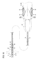
- FIG. 10 is a schematic plan view for describing the yawing operation of the manipulator 10 of FIG. 1
- FIG. 11 is a partial perspective view for describing the yawing operation of the manipulator 10 of FIG. 1
- FIG. 12 is a partial perspective view for describing an assembled condition in the interior of the handle 18 of FIG. 1 .
- two switches 48 (right side switch 48a, left side switch 48b) are mounted on opposite side surfaces of the handle main body 40. Center portions of the right side and left side switches 48a, 48b are supported on the handle 18 (by the first and second brackets 200, 202), and a structure is provided such that both end portions (a distal end portion and a proximal end portion) thereof are displaced about the center portions in response to pushing operation of the switches by the user.
- the right side and left side switches 48a, 48b are structured to be capable of being handled by both left-handed and right-handed users. For example, in the case that the gripping unit 44 is gripped by the right hand, the right side switch 48a can be operated by the index finger of the right hand.
- the right side switch 48a is constituted such that, in the case that the proximal end side (A1 in FIG. 10 ) thereof is pressed, the distal end working unit 14 undergoes a yawing operation in a rightward direction (Y1 direction), and in the case that the distal end side (A2 in FIG. 10 ) thereof is pressed, the distal end working unit 14 undergoes a yawing operation in a leftward direction (Y2 direction).
- the left side switch 48b is constituted such that, in the case that the proximal end side (A2 in FIG.
- the distal end working unit 14 undergoes a yawing operation in a leftward direction (Y2 direction), and in the case that the distal end side (A1 in FIG. 10 ) thereof is pressed, the distal end working unit 14 undergoes a yawing operation in a rightward direction (Y1 direction).
- a switch i.e., the right side switch 48a or the left side switch 48b, the user operates, the feeling of operation of the switches 48 matches with the sense (viewpoint) of the user.
- the operating signals that are generated by operating the switches 48 are of two patterns, i.e., a yawing operation signal in the left direction and a yawing operation signal in the right direction, and the signals are transmitted to the controller 20 (see FIG. 11 ).
- the controller 20 outputs, to the drive motor 46, a drive signal based on the operating signal for controlling the rotational speed, the rotational direction, etc. of the drive motor 46.
- rotation of the drive motor 46 is carried out in the form of a clockwise rotation or a counterclockwise rotation.
- the driving control of the drive motor 46 may adopt various configurations. For example, configurations may be adopted in which, corresponding to the pressing force applied to the switches 48, the rotational speed of the drive motor 46 is varied, or the bending speed of the yawing operation is varied.
- the manipulator 10 is constructed such that, by attaching the drive unit 41 to the handle main body 40, the motor-driven main drive gear 224 that is mounted on the distal end of the drive motor 46 meshes with the motor-driven driven gear 222 in the interior of the handle 18.
- the motor gear pin 220 which is equipped with the motor-driven driven gear 222, is retained rotatably by a first support bar 280 and a second support bar 282, which are erected upwardly from the proximal end side of the second bracket 202.
- the first support bar 280 includes an upper end portion which extends in the direction of the distal end and holds an upper end of the pinion shaft 214.
- the pinion shaft 214 is rotated by the driven bevel gear 216, which abuts against the main drive bevel gear 218 that is disposed on the distal end of the motor gear pin 220, so as to rotate the pinion 80 that is formed on the lower end of the driven bevel gear 216.
- the pinion 80 is arranged in a space that is formed by assembly of the first and second brackets 200, 202.
- the first and second slide members 74, 76 are disposed in confronting relation sandwiching the pinion 80.
- the bar portions 206 of the first and second slide members 74, 76 are supported in the supporting cutouts 210 (see FIG. 9 ) of the first bracket 200.
- the first and second semicircular pipes 70, 72 are connected respectively to the attachment parts 208 that extend downwardly from the bar portions 206. Therefore, when the pinion 80 is rotated in one direction, the first slide member 74 and the second slide member 76 slide mutually in opposite directions, accompanied by the first semicircular pipe 70 and the second semicircular pipe 72 also sliding mutually in opposite directions. Sliding of the first and second semicircular pipes 70, 72 in opposite directions is transferred through the shaft 16 to the distal end working unit 14 on the distal end side.
- FIG. 13A is a side view showing main components of the bending portion 34 of the manipulator 10 of FIG. 1
- FIG. 13B is a plan view showing main components of the bending portion 34 of the manipulator 10
- FIG. 13C is a cross sectional view taken along line XIIIC-XIIIC of FIG. 13B
- FIG. 14A is a partial perspective view showing at an enlarged scale one of the joint members 36 of FIG. 13A
- FIG. 14B is a partial perspective view showing at an enlarged scale an assembled condition of the joint members 36.
- the first and second belts 66, 68 which are connected to the distal ends of the first and second semicircular pipes 70, 72, are inserted through the five joint members 36, and are connected by fixing pins 160 to the outer shell member 32 on the distal end side.
- the bending portion 34 is subjected to a bending operation.
- a structure is provided in which the first and second belts 66, 68 slide along inner side surfaces of the joint members 36.
- guide members 283 that serve to guide the first and second belts 66, 68 are disposed in the center tubular portions 162 of the joint members 36 on an outer side of the hollow parts 162a of the center tubular portions 162.
- the guide members 283 comprise belt spaces 286 (penetrating cavities) that penetrate in the axial direction through the center tubular portion 162, and projecting walls 284 that act as separations between the hollow parts 162a and the belt spaces 286.
- the projecting walls 284 are erected in the hollow parts 162a perpendicularly to the distal end and proximal end hinge pieces 164, 166, which extend in pairs on upper and lower parts of the center tubular portion 162.
- the first and second belts 66, 68 are mounted so as to be inserted through the belt spaces 286 that are separated by the projecting walls 284 (see FIG. 14B ).
- the distal end hinge pieces 164 and the proximal end hinge pieces 166 are formed at positions shifted by 90° with respect to the belt spaces 286 through which the first and second belts 66, 68 are inserted. Accordingly, the distal end hinge pieces 164 and the proximal end hinge pieces 166 are bendably connected by the joint pins 170, and the adjacent joint members 36 are easily bent about the joint pins 170 responsive to sliding of the first and second belts 66, 68.
- the first and second belts 66, 68 are slid (i.e., in the event that the bending portion 34 is subjected to bending), the first and second belts 66, 68 can avoid becoming separated from the inner side surfaces of the center tubular portions 162 by the projecting walls 284, and corresponding to the sliding amount, the joint members 36 can be bent together in conjunction.
- arcuate surfaces 288 through which the hollow tube 82 can be inserted are formed on upper and lower inside surfaces of the joint members 36. In the event that the joint members 36 are bent, the hollow tube 82 bends in following relation thereto as a result of being guided by the arcuate surfaces 288.
- the hollow tube 82 is flexible and is capable of being bent in following relation to the bending movement of the bending portion 34, and as shown in FIG. 13C , a hollow portion 82a is formed therein having an inner diameter that enables insertion of the conductive line 60.
- the second connector 174 is connected to the proximal end side of the hollow portion 82a, and the first connector 142 is connected to the distal end side of the hollow portion 82a.
- a double coil (a first coil 290, a second coil 292) is arranged in the interior of the hollow tube 82 to surround the hollow portion 82a.
- the first and second coils 290, 292 extend axially in an overlapping manner in a state of being wound mutually in different (clockwise, counterclockwise) winding directions. Consequently, when the hollow tube 82 is rotated clockwise, the coil (e.g., the first coil 290) that is wound in the clockwise direction expands in diameter, and the coil (e.g., the second coil 292) that is wound in the counterclockwise direction is reduced in diameter. Therefore, the shape of the double coil overall is maintained. As a result, even if the hollow tube 82 is rotated in a state in which the hollow tube 82 is bent by the bending portion 34, the rotational torque thereof can easily be transmitted to the distal end side (the gripper 12).
- the gripper 12 can be tilted in lateral directions by the yawing operation.
- the user presses the proximal end A1 of the right side switch 48a (or the distal end A1 of the left side switch 48b) (see FIG. 10 ), whereby an operating signal from the switch 48 is sent to the controller 20.
- the controller 20 receives the operating signal and outputs, to the drive motor 46, a predetermined drive signal (electric power), and then the controller 20 rotates the motor-driven main drive gear 224 of the drive motor 46 in a clockwise direction.
- the motor gear pin 220 (and the motor-driven driven gear 222) is rotated in a counterclockwise direction, and the driven bevel gear 216 (and the pinion shaft 214), which is enmeshed with the main drive bevel gear 218, is rotated in a clockwise direction as viewed in plan.
- the pinion 80 is rotated clockwise, whereupon the first slide member 74 is made to slide in the proximal end direction, and the second slide member 76 is made to slide in the distal end direction.
- the first semicircular pipe 70 and the first belt 66 also undergo sliding movement in the proximal end direction.
- the second semicircular pipe 72 and the second belt 68 also undergo sliding movement in the distal end direction. Accordingly, in the bending portion 34, since the axial length of the first belt 66 becomes shorter, whereas the axial length of the second belt 68 becomes longer, the bending portion 34 undergoes a yawing operation and is bent on the side of the first belt 66. As a result, the gripper 12, which is disposed on the distal end side of the bending portion 34, is changed to a rightward tilted posture.
- the bending portion 34 may be constructed such that, during bending of the bending portion 34, the sliding amounts of the first and second belts 66, 68 are changed responsive to the bending direction. More specifically, in the case that the bending portion 34 is bent, the length of the belt (first belt 66) on the inside of the bending direction becomes shorter than the belt on the outside (second belt 68) by an amount that is more than necessary.
- a structure may be provided in which, by interposing non-illustrated gears between the pinion 80 and the racks 78 of the first and second slide members 74, 76 without the pinion 80 meshing directly with the racks 78, the sliding amount of the belt on the inside of the bending direction (i.e., the first belt 66 in the case of the right side, the second belt 68 in the case of the left side) can be reduced.
- FIG. 15 is a schematic side view for describing the rolling operation of the manipulator 10 of FIG. 1
- FIG. 16 is a partial perspective view for describing an assembled condition in the interior of the handle 18 of FIG. 1 .
- the gripper 12 on the distal end of the manipulator 10 is rotated about the axis Or of the gripper 12.
- the axis Or of the gripper 12 (end effector) is defined by the center axis of a portion that extends substantially in a straight line on the distal end side of the bending portion 34 (joint part).
- the axis Or is tilted in the yawing direction with respect to the axis Os of the shaft 16 (see FIG. 4B ).
- the rolling operation is implemented by the user manually operating the rotating handle 50 that is mounted on the distal end of the handle 18.
- the rotating handle 50 is a block shaped member having a width that is smaller than the width of the handle 18 as viewed in plan (see FIG. 10 ).
- the shaft insertion pipe 204 of the first bracket 200 is inserted into the through hole 50a that is provided in the center thereof (see FIG. 9 ). Further, plural blades 50b that make the rotating operation easier for the user are provided on side surfaces of the rotating handle 50.
- a latch gear 294 and a handle main drive gear 238, which rotates together with the rotating handle 50, are disposed on the proximal end side of the rotating handle 50.
- the latch gear 294 and the handle main drive gear 238 are disposed in a distal end part of an interior space of the handle 18.
- the outer side surface of the latch gear 294 is formed in a wavelike shape (irregular surface) by arc-shaped valley portions 296, and mountain portions 298 that bulge upwardly between the valley portions 296.
- a latch piece 300 is configured to abut against the outer side surface of the latch gear 294.
- the latch piece 300 includes a mounting portion 304, which is attached to a mounting plate 302 that extends in the distal end direction from the second bracket 202, and an elastic piece 306 that extends obliquely downward from the mounting portion 304 and is capable of swinging elastically with respect to the mounting portion 304 (see FIG. 9 ).
- the lower end of the elastic piece 306 is formed in an arcuate shape that matches with the valley portions 296 of the latch gear 294, and in a mounted state of the latch piece 300, is in surface contact with the valley portions 296.
- the latch gear 294 also rotates, and by such rotation, the latch piece 300 (the elastic piece 306) swings elastically along the valley portions 296 and the mountain portions 298.
- the handle main drive gear 238 rotates the rotating pin 232 (handle-driven gear 236) that is supported on the first bracket 200.
- the handle-driven gear 236 is formed with a smaller outer diameter than the handle main drive gear 238, and is rotated at a lesser amount of rotation than the amount of rotation of the rotating handle 50.
- the rotary main drive gear 230 which is disposed on the proximal end side of the rotating pin 232, rotates the rotary driven gear 226 that is fixed to the inner tube 86 of the shaft 16, and the rotary driven gear 226 is rotated integrally with the inner tube 86.
- the sliding drive shaft 228 and the slip ring system 270 (excluding the first and second contact terminals 64a, 64b), which are mounted more on the proximal end side than the rotary driven gear 226, rotate together with the inner tube 86.
- the first and second contact terminals 64a, 64b abut elastically against the first and second cylindrical terminals 62a, 62b, so as to remain in contact therewith even though the first and second cylindrical terminals 62a, 62b are rotating.
- steady electrical conduction is realized between the high frequency power source 22 and the conductive line 60 that is arranged in the interior of the inner tube 86.
- FIG. 17 is a perspective view, partially cut away, of main components of a distal end part of the manipulator 10 of FIG. 1
- FIG. 18A is a cross sectional plan view showing a distal end part of the manipulator 10 of FIG. 1
- FIG. 18B is a cross sectional side view showing a distal end part of the manipulator 10 of FIG. 1 .
- the distal end working unit 14 is constituted such that the gripper 12 rotates in the circumferential direction on the distal end side of the bending portion 34. More specifically, by connecting the outer shell member 32 to the distal end of the joint members 36 that constitute the bending portion 34, a structure is provided in which the outer shell member 32 does not rotate. On the other hand, by transferring the rotational torque from the hollow tube 82 that is disposed in the interior of the bending portion 34, a structure is provided in which the gripper 12 and the gripper retaining member 30 are rotated in the circumferential direction about the axis of the gripper 12.
- the hollow tube 82 is connected through the second connector 174 to the inner tube 86 of the shaft 16, whereby the inner tube 86 rotates together with the hollow tube 82 (see FIG. 13C ).
- the distal end of the hollow tube 82 is inserted into the engagement tubular portion 114 of the gripper retaining member 30, and is fitted and connected to the proximal end connecting projection 148 of the first connector 142. Further, the distal end connecting projection 146 of the first connector 142 is fitted into the cylindrical body 138.
- the cylindrical body 138 is formed with an outer diameter that matches substantially with the inner diameter of the engagement tubular portion 114. To the engagement tubular portion 114, the rotational torque is transferred from the cylindrical body 138 that is connected to the hollow tube 82. More specifically, when the hollow tube 82 is rotated and the rotational torque therefrom is transmitted, the first connector 142 and the cylindrical body 138 rotate together integrally, and the gripper retaining member 30 (the engagement tubular portion 114) is rotated accompanying rotation of the cylindrical body 138.
- the insertion part 134 of the aforementioned moving body 94 is inserted in a distal end portion of the cylindrical body 138.
- the retaining plate 128a at the center of the moving body 94 is made of an insulating material, and the retaining plate 128a extends to the proximal end side of the insertion part 134, with welded portions 308 being provided on both upper and lower surfaces of the proximal end part thereof.
- the metal members 56 (metal wires), which are exposed from the distal end of the conductive line 60, are welded by a welding material to the welded portions 308.
- the conductive line 60 extends in the axial direction in the hollow portion 82a of the hollow tube 82 while a distal end part thereof is fixedly retained by the first connector 142.
- the moving body 94 rotates along with the rotation of the cylindrical body 138. Also, by transmitting rotation of the moving body 94 to the gripper retaining member 30, the gripper retaining member 30 is rotated more smoothly.
- first and second gripper members 26, 28 that make up the gripper 12 are supported by the gripper retaining member 30, the first and second gripper members 26, 28 rotate together with rotation of the gripper retaining member 30. More specifically, in the manipulator 10, as shown in FIG. 17 , the gripper 12, the gripper retaining member 30, and the hollow tube 82 are rotated about the axis Or of the gripper 12.
- the rolling operation of the gripper 12 enables the gripper 12 to be rotated through a 360° unlimited range of rotation with respect to the axis Or of the gripper 12.
- the inner tube 86 is rotatable in an unlimited manner with respect to the outer tube 84
- the hollow tube 82 which is arranged at a position overlapping with the bending portion 34, also is rotatable in an unlimited manner.
- the gripper retaining member 30 (gripper 12), which is inserted in the outer shell member 32, is rotatable in an unlimited manner.
- the conductive line 60 extends inside the hollow tube 82 and the inner tube 86, the conductive line 60 rotates together with the hollow tube 82 and the inner tube 86. At this time, conduction of electricity with the high frequency power source 22 at the proximal end side of the conductive line 60 is continued by the slip ring system 270.
- FIG. 19 is a schematic perspective view for describing the opening and closing operation of the gripper 12 of FIG. 1
- FIG. 20A is a first side view for describing operations on the side of the handle 18 of FIG. 19
- FIG. 20B is a second side view for describing operations on the side of the handle 18 of FIG. 19 .
- the trigger 52 is arranged on the lower side of the rotating pin 232 that makes up the rotation mechanism 88, and is supported swingably with respect to the first bracket 200 (handle 18). More specifically, the linkage 264 of the trigger 52 is supported by the second support pin 266 that extends from the first bracket 200, and the extending handle 262 is operated in the distal end and proximal end directions about the second support pin 266.
- the linkage 264 of the trigger 52 is connected to the advancing and retracting movement mechanism 98 that operates the inner tube 86. More specifically, a distal end of the spring link 256 is connected through the second link shaft 260 to an upper portion (link hole 264a) above the insertion position of the second support pin 266 of the linkage 264.
- the spring link 256 is arranged to extend in the proximal end direction, and the proximal end thereof is connected through the first link shaft 254 to a lower end portion (lower side hole 246b) of the responsive member 246.
- the second support pin 266 that extends from the first bracket 200 is inserted into the upper side hole 246a of the responsive member 246, and the projecting portion 248 (see FIG. 9 ) of the pair of arms 250 that extend upwardly above the upper side hole 246a is inserted into the recessed portion 244 of the sliding drive shaft 228.
- the trigger 52 rotates about the second support pin 266, and the upper end (the connection location of the spring link 256) of the linkage 264 is moved in the direction of the distal end.
- the spring link 256 also moves in the distal end direction, whereby the lower end of the responsive member 246 is made to move in the distal end direction.
- the responsive member 246 rotates about the first support pin 252, and the arms 250 on the upper end side are made to move in the direction of the proximal end.
- the sliding drive shaft 228 (recessed portion 244) is pressed by the projecting portion 248 and moves in the direction of the proximal end.
- the inner tube 86 moves in the proximal end direction together with the sliding drive shaft 228, and the operating force in the proximal end direction is transferred through the shaft 16 to the distal end working unit 14 on the distal end side.
- the spring member 258 of the spring link 256 expands elastically, and serves to suppress movement of the inner tube 86 in the proximal end direction.
- the movement amount when the inner tube 86 is moved in the proximal end direction is limited to the degree at which the gripper 12 shifts to the closed state from the open state, and in the case that the trigger 52 is pulled beyond the above degree, the operating force is absorbed by elastic deformation of the spring member 258.
- movement of the inner tube 86 in the proximal end direction is of a degree that enables transitioning from the condition shown in FIG. 20A to the condition shown in FIG. 20B .
- the axial length of the rotary driven gear 226 and the two cylindrical terminals 62, which are mounted on the inner tube 86, is set to be longer than the movement amount in advancing and retracting directions of the inner tube 86. Therefore, even in the case that the trigger 52 is operated and the inner tube 86 is moved in the proximal end direction, the rotary main drive gear 230 can mesh continuously with the rotary driven gear 226, and the first and second contact terminals 64a, 64b can remain in contact continuously with the first and second cylindrical terminals 62a, 62b. Consequently, while the inner tube 86 undergoes rotation (i.e., while the rolling operation of the gripper 12 is carried out), opening and closing of the gripper 12 can be performed, and current can be supplied to energize the treatment target X.
- FIG. 21A is a principal plan view showing the gripper 12 of FIG. 1
- FIG. 21B is a partial plan view showing an open state of the gripper 12
- FIG. 21C is a partial plan view showing a closed state of the gripper 12.
- the operating force that moves the inner tube 86 in the distal end and proximal end directions is transmitted to the hollow tube 82, which is connected to the distal end of the inner tube 86, whereby the hollow tube 82 is made to move in the distal end and proximal and directions.
- the cylindrical body 138 is connected through the first connector 142 to the distal end of the hollow tube 82, and the cylindrical body 138 also is made to move together with the hollow tube 82.
- the length in the axial direction of the hollow tube 82 is longer than the axial length of the bending portion 34 of the distal end working unit 14, such that even if the hollow tube 82 is advanced and retracted, the hollow tube 82 is arranged to overlap with the bending portion 34 at all times. Accordingly, even if the bending portion 34 is subjected to bending as shown in FIG. 11 , and the hollow tube 82 bends in following relation thereto, the hollow tube 82 can be advanced and retracted along the bend, and the operating force of the advancing and retracting movement can be transmitted to the cylindrical body 138 that is connected to the distal end side of the hollow tube 82.
- connecting pins 310a, 310b which project inwardly (into the hollow space 140) by a predetermined amount, are disposed on the distal end side and the proximal end side of the cylindrical body 138.
- the first connector 142 is equipped with a first connector side engagement groove 312, which is engraved in a circumferential direction in a root portion of the distal end connecting projection 146.
- the proximal end side connecting pin 310a is inserted into the first connector side engagement groove 312.
- the moving body 94 is equipped with a moving body side engagement groove 314, which is engraved in a circumferential direction in the insertion part 134 that projects in the proximal end direction.
- the distal end side connecting pin 310b is inserted into the moving body side engagement groove 314.
- the axial connections between the first connector 142, the cylindrical body 138, and the moving body 94 are reinforced by the connecting pins 310a, 310b, and the operating force of the advancing and retracting movement, which is transmitted from the hollow tube 82, is further transmitted reliably to the moving body through the cylindrical body 138.
- the gripper retaining member 30 is placed in a condition in which the moving body 94 is arranged in the sliding space 122 thereof, and the gripper retaining member 30 remains fixed with respect to movements of the moving body 94 in the distal end and proximal end directions. More specifically, by engagement between the projection 120, which is formed on the outer side surface of the engagement tubular portion 114, and the groove 154, which is formed on the inner side surface of the outer shell member 32, the gripper retaining member 30 is placed in a fixed state in which back and forth movement thereof is restricted, in contrast to the advancing and retracting movements of the moving body 94.
- the first and second gripper members 26, 28 are sandwiched between the gaps 130 of (the three-pronged moving body side section 132 of) the distal end, and the movable pin 96, which is inserted in the long holes 92 of the extension pieces 90, is retained therein.
- the movable pin 96 is moved to the distal end side of the long holes 92, and the distal end portions of the first and second gripper members 26, 28 are separated and placed in an open condition.
- the movable pin 96 moves in the proximal end direction while guiding the long holes 92, and based on the guiding of the long holes 92, the distal end parts of the first and second gripper members 26, 28 are made to approach one another mutually, and a closed condition can be obtained.
- a current supplying condition is formed by the connection of the first and second gripper members 26, 28, which are of different polarities. More specifically, in a state in which the treatment target X is sandwiched between the first and second gripper members 26, 28, an output, which is supplied to the first and second gripper members 26, 28 through the conductive line 60 from the high frequency power source 22, is supplied to the treatment target X, and a predetermined process (cauterization by application of heat, or the like) is performed thereon.
- the hollow tube 82 that is disposed in a position overlapping with the bending portion 34 bends in following relation with the yawing operation of the bending portion 34. Therefore, for example, even in the case that the treatment target X is located deeply inside the living body, the posture (inclination) of the gripper 12 can easily be changed, and the gripper 12 can be delivered smoothly to the treatment target X.
- an operating force in the direction of rotation is transmitted to the gripper 12 by the hollow tube 82, whereby the gripper 12 is rotated (subjected to a rolling operation) through an unlimited range of rotation. Therefore, the posture of the gripper 12 (i.e., a posture in the direction of rotation around the roll axis Or of the gripper 12) on the distal end side of the bending portion 34 can be changed freely, and the orientation of the gripper 12 can be changed any number of times to match with the treatment target X, and to enable an accurate treatment to be carried out on the treatment target X.
- the bending portion 34 can be bent gently and gradually. Therefore, the hollow tube 82, which is disposed at a position overlapping with the bending portion 34, can easily follow the bending movement of the bending portion 34. In addition, since the hollow tube 82 extends a greater length than the bending portion 34, the operating force in the direction of rotation and the operating force in the distal end and proximal end directions, which are transmitted from the inner tube 86, can be transferred smoothly beyond the bending portion 34 to the distal end side (gripper 12).
- the opening and closing operation of the gripper 12 can easily be carried out. Consequently, the treatment target X can easily be gripped by the gripper 12, and a predetermined procedure (energizing treatment) can be performed efficiently on the treatment target X.
- the operating forces in the distal end and proximal end directions may be used not only for carrying out an opening and closing operation of the gripper 12, but also for carrying out, for example, an operation for moving, in the distal end and proximal end directions, the end effector as it is.
- the gripper 12 that is held by the gripper retaining member 30 can be rotated suitably.
- the projection 120 of the gripper retaining member 30 is inserted rotatably in the groove 154 of the outer shell member 32, whereby rotation of the gripper retaining member 30 is guided by the groove 154.
- the gripper 12 can be rotated more smoothly, and the gripper 12 can be oriented in a desired posture.
- the strength of the hollow tube 82 can be increased. More specifically, the rotational operating forces that are transmitted from the inner tube 86 can be transferred smoothly to the gripper 12 through the hollow tube 82, the strength of which is increased and the shape of which is maintained.
- the manipulator 10 even if the hollow tube 82, which is disposed in a position overlapping with the bending portion 34, is subjected to bending by the bending portion 34, the operating force from the inner tube 86 is transferred to the distal end side (the gripper retaining member 30 and the moving body 94) relative to the bending portion 34, while the hollow tube 82 remains in a bent condition.
- the distal end side the gripper retaining member 30 and the moving body 94
- a conductive path leading to the gripper 12 which is constituted as a bipolar type of electrosurgical knife, can easily be constructed, and electrical power can be supplied stably to the gripper 12.
- the hollow tube 82 is rotated by the operating force, and the gripper 12, which is connected to the distal end side of the hollow tube 82, is made to undergo a rolling operation, whereby the gripper 12 can be made to face toward the treatment target X at a desired posture.
- the gripper 12 can be made to face toward the treatment target X at a desired posture.
- the slip ring system 270 is provided in the manipulator 10. Specifically, a structure is enabled in which the contact terminals 64 are electrically connected to the cylindrical terminals 62 during times that the cylindrical terminals 62 are rotating and at rest. Consequently, even if the inner tube 86 is rotated in order for the gripper 12 to undergo the rolling operation, conduction of electricity with the high frequency power source 22 can continuously be maintained. Accordingly, even if the posture of the gripper 12 in the direction of rotation is changed, an electrical treatment can suitably be carried out.
- the hollow tube 82 is advanced and retracted together with movement of the inner tube 86, whereby the gripper 12 can be opened and closed.
- the gripper 12 can be opened and closed.
- the gripper 12 can easily be bent in a direction that differs from the axis Os of the shaft 16. Further, through application of the first and second belts 66, 68, the alignment of the plural joint members 36 can stably be maintained. For example, an operation to restore the bending portion 34 to its origin (where the bending portion 34 is aligned with the axial direction of the shaft 16) or the like can be performed quickly and accurately.
- the plural joint members 36 can smoothly be bent together in conjunction.
- the belts are not limited to the structure described above in which a pair (two) of such belts are disposed on the bending portion 34, and one or three or more of such belts may be provided.
- the bending portion 34 can be bent smoothly.
- the gripper 12 can easily be tilted to the side of the first belt 66.
- the rotational driving force of the pinion 80 can easily be converted into operating forces in the distal end and proximal end directions of the first and second slide members 74, 76.
- the operating forces can be transmitted easily to the first and second belts 66, 68 through the first and second semicircular pipes 70, 72.
- the rotational amount of the pinion 80 the amount by which the bending portion 34 curves (i.e., the tilt angle of the gripper 12) can be changed freely.
- the first and second belts 66, 68 being guided by the guide members 283, the first and second belts 66, 68 move smoothly with respect to the center tubular portion 162, and the operating force that moves the first and second belts 66, 68 in the distal end and proximal end directions can easily be transferred to the surrounding joint members 36.
- the bending portion 34 is bent, outward bulging of the first and second belts 66, 68 can be suppressed.
- various transmission members that serve to operate the end effector (gripper 12) can appropriately be arranged in the hollow parts 162a.
- the guide members 283 are equipped with the projecting walls 284 that function as separations between the hollow parts 162a and the belt spaces 286.
- the arcuate surfaces 288 that are capable of contacting the hollow tube 82 on the inner side surface of the center tubular portions 162 in the case that the bending portion 34 is bent, the hollow tube 82 that is inserted through the interior of the center tubular portions 162 can also easily be bent.
- the inner tube 86 can be moved in the distal end and proximal end directions, and the inner tube 86 can be rotated.
- Two types of operating forces of the inner tube 86 are transmitted to the gripper 12 of the distal end working unit 14 that is disposed on the distal end of the shaft 16, whereby variations in posture and opening and closing operations of the gripper 12 can be carried out easily.
- the rotary driven gear 226 and the rotary main drive gear 230 of the rotation mechanism 88 are formed to be longer than the movement amount of the inner tube 86 performed by the advancing and retracting movement mechanism 98, even if the inner tube 86 is moved in the distal end and proximal end directions by the advancing and retracting movement mechanism 98, the rotary driven gear 226 and the rotary main drive gear 230 can be kept in meshing engagement with each other at all times.
- the inner tube 86 can be rotated in a stable fashion.
- the rotating handle 50 by disposing the rotating handle 50 at a position in the vicinity of the handle 18, in a state in which the user of the manipulator 10 has gripped the handle 18, the user can easily manipulate the rotating handle 50, which is in such a nearby position. Further, by forming the rotating handle 50 to be narrower than the width of the handle 18, in the case that multiple medical devices (a forceps, a manipulator 10, etc.) are used during a procedure, interference of the rotating handle 50 with such medical devices can be reduced.
- multiple medical devices a forceps, a manipulator 10, etc.
- the latch gear 294 that rotates accompanying rotation of the rotating handle 50 and the latch piece 300 that abuts elastically against the latch gear 294, when the rotating handle 50 is operated, a latching sensation can be imparted to the user. Consequently, the user can recognize intuitively the amount of rotation of the rotating handle 50, and can easily adjust the rotation of the inner tube 86.
- the projecting portion 248 is displaced in the distal end and proximal end directions
- the sliding drive shaft 228 including the recessed portion 244 in which the projecting portion 248 is inserted also is displaced in the distal end and proximal end directions. Accordingly, the inner tube 86 on which the sliding drive shaft 228 is installed can move smoothly in the distal end and proximal end directions. Further, since the recessed portion 244 is formed in the circumferential direction, the sliding drive shaft 228 can rotate relatively with respect to the projecting portion 248, and with a simple structure, rotation of the inner tube 86 can be allowed.
- the manipulator 10 With the manipulator 10 according to the present embodiment, high operability of the gripper 12 that is inserted in the interior of the living body can be obtained, and the procedure performed on the treatment target X can be conducted efficiently and accurately.
- the present invention is not limited to the above embodiment and various changes and modifications may be made to the embodiment without departing from the scope of the invention as set forth in the appended claims.
- the manipulator 10 among the yawing operation, the rolling operation, and the opening and closing operation, any one or two or more of these operations can be constituted as an electrically driven operation, or alternatively the yawing operation, the rolling operation, and the opening and closing operation can all be constituted as manually driven operations.
Abstract
Description
- The present invention relates to a medical manipulator by which an end effector can be inserted into the interior of a living body for enabling a treatment to be carried out on a treatment target.
- In a surgical treatment, without performing a thoracotomy or a laparotomy with respect to a patient, small holes are opened in the body, forceps, scissors, or the like are introduced into the body through the holes, and a desired surgical treatment (a so-called endoscopic surgical procedure) is carried out on diseased biological tissue or the like in the body. Recently, in this type of treatment, in addition to forceps or scissors, a medical manipulator is used, which is capable of performing operations with a higher degree of freedom in the living body.
- For example, with the medical manipulator disclosed in Japanese Laid-Open Patent Publication No.
2011-072570 - In the case that a surgical treatment is carried out using the medical manipulator, a plurality of holes are opened in the abdomen or the like of a patient, and an endoscope (camera) and a forceps or the like are inserted into the body cavity, together with inserting a distal end (gripper) of the medical manipulator. Consequently, under observation of the camera, the gripper is delivered to the site of a living tissue (treatment object) in the body, and by a closing operation of the gripper, the living tissue is gripped while electrical current is applied to the living tissue. During delivery of the gripper or when a treatment on the living tissue is performed, based on the operating force transmitted from the main body portion, the state of the gripper (the posture or the opening/closing condition thereof) can freely be changed at locations in the living body.
- The present invention has been devised in relation to the above-described medical manipulator, and has the object of providing a medical manipulator, which enhances the operability of an end effector that carries out a treatment on a treatment target, whereby the treatment can be implemented efficiently and with improved accuracy.
- To accomplish the aforementioned objects, the present invention is characterized by a medical manipulator including a shaft, a distal end working unit provided on a distal end of the shaft and having an end effector configured to carry out a treatment on a treatment target, and a main body portion disposed on a proximal end of the shaft and configured to operate the end effector based on an input from a person. The distal end working unit includes a bending portion disposed between the end effector and the shaft and which causes the distal end working unit to bend in a direction that differs from an axial direction of the shaft, in accordance with an operating force in the bending direction that is transmitted from the main body portion, and a tube, which is disposed at a position overlapping with the bending portion and is capable of bending in following relation to the movement of the bending portion. The tube transmits a rotational operating force, which is transmitted from the main body portion, to the end effector, so as to enable the end effector to be rotated through an unlimited range of rotation.
- According to the above description, the tube that is disposed in a position overlapping with the bending portion bends in following relation with the movement of the bending portion. Therefore, for example, even in the case that the treatment target is located deeply inside the living body, the posture of the end effector can easily be changed, and the end effector can be delivered smoothly to the treatment target. Further, the tube delivers the operating force in the rotational direction to the end effector, and the end effector is capable of rotating through an unlimited range of rotation, whereby the posture of the end effector at the distal end side of the bending portion can freely be changed, and a precise treatment can be carried out by changing the orientation of the end effector any number of times to conform with the treatment target. More specifically, high operability for the end effector is obtained, and the procedure performed on the treatment target can be conducted efficiently and accurately.
- The bending portion may include a structure in which three or more rigid joint members are arrayed in the axial direction, and the adjacent joint members are connected to each other so as to bend mutually. Further, the tube may extend over a length that is longer than the axial length of the bending portion.
- In this manner, with a structure in which three or more joints are subjected to bending, the bending portion can be bent gently and gradually. Further, the tube, which extends a greater length than the bending portion, easily bends in following relation to the bending portion, so that even in a bent state, the operating force in the direction of rotation can be transferred smoothly to the end effector.
- The distal end working unit may transmit operating forces in a distal end direction and a proximal end direction, which are transferred from the main body portion, to the end effector through the tube.
- In this manner, by transferring operating forces in the distal end and proximal end directions, to the end effector through the tube, the end effector can be caused to carry out various operations by the operating forces in the distal end and proximal end directions.
- In this case, the end effector is a gripper in which first and second gripper members are opened and closed to grip the treatment target. The gripper can close the first and second gripper members by the operating force in the proximal end direction that is transmitted through the tube, and can open the first and second gripper members by the operating force in the distal end direction that is transmitted through the tube.
- In this manner, assuming a structure is provided in which the first and second gripper members are opened and closed by operating forces in the distal end and proximal end directions, the treatment target can easily be sandwiched and gripped between the gripper members, and a predetermined treatment can be performed efficiently.
- Furthermore, the distal end working unit may include an outer shell member connected to a distal end of the bending portion, and a retaining member, which retains the end effector under a condition in which at least a portion of the retaining member is accommodated in the interior of the outer shell member, and is rotated relatively with respect to the outer shell member by the rotational operating force from the tube.
- Consequently, since the tube and the retaining member can be rotated relatively with respect to the bending portion and the outer shell member, the end effector that is held on the retaining member can be rotated suitably.
- In this case, the outer shell member may include a groove that is engraved in a circumferential direction on an inner wall confronting an outer surface of the retaining member, and the retaining member may include a projection that is inserted rotatably in the groove.
- In this manner, by inserting the projection of the retaining member rotatably in the groove, rotation of the retaining member is guided by the groove, and therefore, the retaining member (i.e., the end effector) can be rotated more reliably.
- Further, plural coils may be disposed in the interior of the tube in an overlapping manner so as to surround a hollow portion that extends in the axial direction, and at least two coils among the plural coils may be wound in mutually different winding directions.
- In this manner, by arranging the two coils, which are wound in different winding directions, in the interior of the tube, the strength of the tube can be increased. As a result, the rotational operating forces from the shaft can be transferred smoothly to the end effector through the tube.
- According to the present invention, the operability of an end effector that carries out a treatment on a treatment target can be improved, whereby the treatment can be implemented efficiently and with improved accuracy.
-
-
FIG. 1 is a perspective view showing the overall structure of a medical manipulator according to an embodiment of the present invention; -
FIG. 2 is a perspective view showing an enlarged representation of main components of a distal end working unit of the manipulator ofFIG. 1 ; -
FIG. 3A is a first schematic view for describing in outline an energizing operation of the manipulator ofFIG. 1 ; -
FIG. 3B is a second schematic view for describing in outline the energizing operation of the manipulator ofFIG. 1 ; -
FIG. 4A is a first schematic view for describing in outline a yawing operation of the manipulator ofFIG. 1 ; -
FIG. 4B is a second schematic view for describing in outline the yawing operation of the manipulator ofFIG. 1 ; -
FIG. 5 is a schematic view for describing in outline a rolling operation of the manipulator ofFIG. 1 ; -
FIG. 6A is a first schematic view for describing in outline an opening and closing operation of the manipulator ofFIG. 1 ; -
FIG. 6B is a second schematic view for describing in outline the opening and closing operation of the manipulator ofFIG. 1 ; -
FIG. 7 is a partial exploded perspective view showing an enlarged representation of a distal end side of the manipulator ofFIG. 1 ; -
FIG. 8 is a partial exploded perspective view showing an enlarged representation of a bending portion of the manipulator ofFIG. 1 ; -
FIG. 9 is a partial exploded perspective view showing an enlarged representation of a handle of the manipulator ofFIG. 1 ; -
FIG. 10 is a schematic plan view for describing the yawing operation of the manipulator ofFIG. 1 ; -
FIG. 11 is a partial perspective view for describing the yawing operation of the manipulator ofFIG. 1 ; -
FIG. 12 is a partial perspective view for describing an assembled condition in the interior of the handle ofFIG. 1 ; -
FIG. 13A is a side view showing main components of the bending portion of the manipulator ofFIG. 1 ; -
FIG. 13B is a plan view showing main components of the bending portion of the manipulator; -
FIG. 13C is a cross sectional view taken along line XIIIC-XIIIC ofFIG. 13B ; -
FIG. 14A is a partial perspective view showing at an enlarged scale a joint member ofFIG. 13A ; -
FIG. 14B is a partial perspective view showing at an enlarged scale an assembled condition of the joint members; -
FIG. 15 is a schematic side view for describing the rolling operation of the manipulator ofFIG. 1 ; -
FIG. 16 is a partial perspective view for describing an assembled condition in the interior of the handle ofFIG. 1 ; -
FIG. 17 is a perspective view, partially cut away, of main components of a distal end part of the manipulator ofFIG. 1 ; -
FIG. 18A is a cross sectional plan view showing a distal end part of the manipulator ofFIG. 1 ; -
FIG. 18B is a cross sectional side view showing a distal end part of the manipulator ofFIG. 1 ; -
FIG. 19 is a schematic perspective view for describing an opening and closing operation of the gripper ofFIG. 1 ; -
FIG. 20A is a first side view for describing operations on the side of the handle ofFIG. 19 ; -
FIG. 20B is a second side view for describing operations on the side of the handle ofFIG. 19 ; -
FIG. 21A is a principal plan view showing the gripper ofFIG. 1 ; -
FIG. 21B is a partial plan view showing an open state of the gripper; and -
FIG. 21C is a partial plan view showing a closed state of the gripper. - Hereinafter, a preferred embodiment of a medical manipulator according to the present invention will be described in detail below with reference to the accompanying drawings.
-
FIG. 1 is a perspective view showing the overall structure of the medical manipulator according to the present embodiment. The medical manipulator (hereinafter referred to simply as a "manipulator 10") according to the present embodiment is used in an endoscopic surgical procedure, and is configured to carry out a predetermined process (e.g., cauterization by application of heat) by applying electrical energy to a living tissue that serves as a treatment target X. As a biological tissue that serves as the treatment target X on which themanipulator 10 performs a treatment, for example, tumors (lesions), muscles, blood vessels, or nerves, etc., may be cited. - The end effector of the
manipulator 10 is constituted as a gripper 12 (electrosurgical knife) that applies electrical energy to the treatment target X by gripping the treatment target X. In the interior of themanipulator 10, various mechanisms are provided for implementing delivery and gripping (an energizing operation) of thegripper 12. Below, a detailed description will be given concerning themanipulator 10. - As shown in
FIG. 1 , themanipulator 10 comprises a distalend working unit 14 having agripper 12 for carrying out a surgical procedure on the treatment target X, ashaft 16 connected to a proximal end side of the distalend working unit 14 and which extends in the direction of the proximal end, and a handle 18 (main body portion) disposed on the proximal end side of theshaft 16, and which operates the distalend working unit 14 based on an operation (input) from a person or user of themanipulator 10. Further, acontroller 20 is connected to thehandle 18 of themanipulator 10 for supplying desired electrical power when the distalend working unit 14 is operated. In addition, a highfrequency power source 22 for energizing (supplying high frequency voltage) to thegripper 12 is connected to thehandle 18. - Upon use of the
manipulator 10, thehandle 18 is gripped and operated by the user (an operator such as a doctor or the like), and a distal end side of the manipulator 10 (the distalend working unit 14 and the distal end side of the shaft 16) is inserted into the body of a patient. At this time, the user opens a small diameter hole at a predetermined position on the body surface of the patient, installs atrocar 24 together with injecting a carbon dioxide gas, and inserts theshaft 16 into the patient via thetrocar 24. Further, in a state in which the distal end side of themanipulator 10 is inserted into the body, while observations are made through an endoscope, variations in posture and opening and closing operations of thegripper 12 are carried out appropriately. Consequently, thegripper 12 is delivered to the site of the treatment target X, and a procedure is performed to supply electrical current to the treatment target X. - The structure of the end effector is not limited to a
gripper 12 that supplies current to the treatment target X, and various alternative structures may be adopted for the end effector. For example, as the end effector, there may be applied a scissors or a surgical knife (blade) for cutting living tissue. Further, the end effector may be constituted as a gripping device for gripping a medical device (forceps, needle, etc.), and a surgical procedure can be performed on the treatment target X by the medical device that is gripped. - As shown in
FIG. 2 , variations in posture and opening and closing operations of thegripper 12 are implemented on a distalend working unit 14 on the distal end of themanipulator 10. As changes in the posture of thegripper 12, there may be cited a yawing operation by which thegripper 12 is tilted so as to curve in a lateral direction (yawing direction) with respect to an axis Os of theshaft 16, and a rolling operation in which thegripper 12 is rotated about an axis Or of thegripper 12. Naturally, the variations in posture of thegripper 12 are not limited to a yawing operation and a rolling operation. For example, a pitch operation may be performed in which thegripper 12 is tilted in a vertical direction (pitch direction) with respect to the axis Os of theshaft 16. - The
gripper 12 is constituted from two gripper members (first gripper member 26, second gripper member 28), which are held while being capable of opening and closing by agripper retaining member 30. Distal end parts of the first andsecond gripper members gripper retaining member 30. The proximal end side of thegripper retaining member 30 is inserted rotatably through a cylindrically shapedouter shell member 32. A bending portion 34 (joint part) that carries out the yawing operation of the distalend working unit 14 is connected to the proximal end side of theouter shell member 32. - The bending
portion 34 is constituted by juxtaposing in the axial direction a plurality of joint members 36 (five are shown inFIG. 2 ), which are made of a hard material, for example, stainless steel (hereinbelow, a description will be given in which the letters A through E are appended to each of the respectivejoint members 36 in order from the distal end side). The adjacentjoint members 36 are connected so as to be mutually rotatable abouthinge members 38. Further, concerning thejoint members 36, thejoint member 36A on the furthest most distal end side is connected in a bendable fashion to theouter shell member 32, whereas thejoint member 36E on the furthest most proximal end side is connected and fixed to the distal end of theshaft 16. In the present embodiment, although stainless steel is used as the material for thejoint members 36, the invention is not limited to this feature, insofar as thejoint members 36 are excellent in durability and are capable of realizing the functions of the present invention. For example, a polyether ether ketone resin (PEEK) may be used. - The yawing operation of the distal
end working unit 14 is implemented by continuing to bend in a linked manner the fivehinge members 38 about the operational fulcrum of thejoint member 36E. Stated otherwise, by theouter shell member 32 and thejoint members 36A through 36D being inclined in a yawing direction at substantially the same angle, thegripper 12 and thegripper retaining member 30 on the distal end side of the bendingportion 34 are tilted integrally. The movable range of the yawing operation of the bendingportion 34 can be set appropriately. For example, if the movable range is set up to a range at which the roll axis Or of thegripper 12 becomes perpendicular to the axis Os of theshaft 16, i.e., a range in which thegripper 12 can be tilted to the left and right, that is, tilted 180°, the facing orientation of thegripper 12 can be varied over a wide range within the body. - On the other hand, the rolling operation of the distal
end working unit 14 is carried out by rotating thegripper retaining member 30 relatively to theouter shell member 32. Stated otherwise, theouter shell member 32 that is connected to the bendingportion 34 is maintained in a fixed condition with respect to the direction of rotation, and thegripper retaining member 30 rotates with respect to theouter shell member 32. Therefore, thegripper 12 and thegripper retaining member 30 rotate together in unison. Further, in the present embodiment, the movable range (range of rotation of the gripper 12) of the rolling operation is unlimited. - Furthermore, the opening and closing operation of the
gripper 12 is carried out by opening and closing the first andsecond gripper members second gripper members gripper retaining member 30. The opening and closing operation of thegripper 12 can be realized at a desired timing based on operations of the user, regardless of any change in the posture of thegripper 12. - In the present embodiment, the variation in posture (the yawing operation and the rolling operation) of the
gripper 12 and the opening and closing operation of thegripper 12 are carried out based on operating forces that are transmitted from theshaft 16 to the distalend working unit 14. - Returning to
FIG. 1 , theshaft 16 that is connected to the distalend working unit 14 extends in a straight line over a predetermined length (e.g., 350 mm), and thehandle 18 is connected to a proximal end portion of theshaft 16. Theshaft 16 includes a function to transfer operating forces from thehandle 18 to the distalend working unit 14. Further, during a surgical procedure, the proximal end side of theshaft 16 is exposed outside the body of the patient, and by manipulating the position and angle of the manipulator 10 (shaft 16) from the outside, the insertion angle and insertion amount of the distalend working unit 14 that is inserted in the body are changed. - The
handle 18 includes a handlemain body 40 that is formed in the shape of a pistol for enabling easy gripping thereof by one hand of the user, and adrive unit 41 that is capable of being attached to and detached from an upper proximal end side portion of the handlemain body 40. The handlemain body 40 includes abody portion 42, which extends in the same direction as the axial direction of theshaft 16, and agripping unit 44 that extends downwardly from a lower side of thebody portion 42. - The
body portion 42 includes an internal space (not shown) having a comparatively large volume, and is provided with various mechanisms in the internal space for effecting operations (the yawing operation, the rolling operation, the opening and closing operation of the gripper 12) of the above-described distalend working unit 14. On the other hand, a drive motor 46 (seeFIG. 11 ) that serves as a drive source for the yawing operation of the distalend working unit 14 is accommodated in the interior of thedrive unit 41. Further, theaforementioned controller 20 and the highfrequency power source 22 are connected to thedrive unit 41. Thecontroller 20 is connected to a non-illustrated power source, and includes a function to control rotary driving of thedrive motor 46. The highfrequency power source 22 includes a function to supply power (high frequency voltage) to thegripper 12 based on manipulations performed by the user. - Switches 48 (tilting operation unit) that carry out the yawing operation of the distal
end working unit 14 are connected to side surfaces of thebody portion 42. Further, a rotating handle 50 (rolling operation unit) that carries out the rolling operation of the distalend working unit 14 is disposed in surrounding relation to an outer side of theshaft 16 at a portion where theshaft 16 is connected to the distal end side of thebody portion 42. Furthermore, a trigger 52 (opening and closing operation unit) that carries out the opening and closing operation of thegripper 12 is disposed in front of the grippingunit 44 on a lower side of thebody portion 42. - The gripping
unit 44 is formed somewhat more toward the distal end side than a middle region in the axial direction of thebody portion 42, and has a structure such that, in a condition in which a user grips the grippingunit 44 with one hand, theswitches 48, therotating handle 50, and thetrigger 52 can be operated by a finger of the one hand that has gripped the grippingunit 44. - Operations of the distal
end working unit 14 are carried out by theswitches 48, therotating handle 50 and thetrigger 52 being manipulated suitably by the user. Themanipulator 10 according to the present embodiment performs a treatment on the treatment target X by mutually linking changes in posture (the yawing operation, the rolling operation) and the opening and closing operation of thegripper 12, and an energizing operation based on the opening and closing operation of thegripper 12. In the following description, to facilitate understanding of the invention, structures related to such operations will be described separately below in outline. -
FIG. 3A is a first schematic view for describing in outline the energizing operation of themanipulator 10 ofFIG. 1 , andFIG. 3B is a second schematic view for describing in outline the energizing operation of themanipulator 10 ofFIG. 1 . First, a structure for enabling the energizing operation of themanipulator 10 will be described in outline. - As described above, the
manipulator 10 includes a function to supply electrical current to the treatment target X while the treatment target X is gripped by thegripper 12. Therefore, the first andsecond gripper members gripper 12 according to the present embodiment is a bipolar type of electrosurgical knife. Naturally, the invention is not limited to such a structure, and the end effector may be constituted as a monopolar type of electrosurgical knife. - The
first gripper member 26 and thesecond gripper member 28 are pivotally supported in an insulated state by a single fulcrum pin 54 (seeFIG. 2 ). When the operating force of the opening and closing operation is received, the distal end parts of the first andsecond gripper members fulcrum pin 54. Therefore, although supply of current is interrupted in an open state in which the distal end parts of the first andsecond gripper members second gripper members second gripper members - Respective metal members 56 (conductive paths) are connected electrically to the proximal end sides of the first and
second gripper members members 58 at portions thereof that extend along the bendingportion 34 and theshaft 16, and the two insulatingmembers 58 extend in the form of a single combinedconductive line 60 as a result of being joined by welding or an adhesive. Theconductive line 60 extends toward the proximal end together with theshaft 16, and is inserted into thehandle 18. In the present embodiment, theconductive line 60 is arranged to pass through the axial center (axis Os) of the bendingportion 34 and theshaft 16. Consequently, since there is no need to provide separate wiring for the conductive line on the side surface of the distalend working unit 14 or theshaft 16, entanglement of the conductive line by operating the distalend working unit 14 is avoided, and supply of current can suitably be performed. - The
conductive line 60 extends to the proximal end side of theshaft 16 that is inserted into the interior of thehandle 18, and the twometal members 56 in theconductive line 60 are connected respectively to a pair of cylindrical terminals 62 (rotating terminals) that are disposed on theshaft 16.Contact terminals 64 are in contact respectively with the pair ofcylindrical terminals 62, and thecontact terminals 64 are connected to the highfrequency power source 22 externally of thehandle 18. -
FIG. 4A is a first schematic view for describing in outline the yawing operation of themanipulator 10 ofFIG. 1 , andFIG. 4B is a second schematic view for describing in outline the yawing operation of themanipulator 10 ofFIG. 1 . Next, a structure for implementing the yawing operation will be described in outline. - As described above, the yawing operation of the
manipulator 10 is realized by the bendingportion 34 that is connected to the distalend working unit 14. On inner side surfaces in the width direction of the fivejoint members 36 that are arrayed in the axial direction, a pair of belts (afirst belt 66 and a second belt 68) are inserted. The respectivejoint members 36 hold the first andsecond belts second belts outer shell member 32, and the proximal end sides thereof are connected to a pair of semicircular pipes (firstsemicircular pipe 70, second semicircular pipe 72: bending operation force transmitting members) that extend inside theshaft 16. - The first and second
semicircular pipes shaft 16 extending to thehandle 18, and are connected to a pair of slide members (first slide member 74, second slide member 76), which are disposed in the interior of thehandle 18. The first andsecond slide members racks 78 being formed respectively on confronting surfaces thereof. Further, between the first andsecond slide members racks 78. Thepinion 80 is connected mechanically to thedrive motor 46 through a plurality of gears, which will be described later. - With the
manipulator 10, which is constructed in this manner, for example, as shown inFIG. 4B , when thepinion 80 is rotated clockwise by rotary driving of thedrive motor 46, thefirst slide member 74 undergoes sliding movement in the proximal end direction, and thesecond slide member 76 undergoes sliding movement in the distal end direction. Therefore, the firstsemicircular pipe 70, which is connected to thefirst slide member 74, also undergoes sliding movement in the proximal end direction, and the secondsemicircular pipe 72, which is connected to thesecond slide member 76, also undergoes sliding movement in the distal end direction. The operating forces of the first and secondsemicircular pipes - More specifically, by the
first belt 66 being moved relatively to the bendingportion 34 in the proximal end direction, thefirst belt 66 in the bendingportion 34 becomes shorter, and by thesecond belt 68 being moved relatively to the bendingportion 34 in the distal end direction, thesecond belt 68 in the bendingportion 34 becomes longer. As a result, the fivejoint members 36 tilt in conjunction to the side of the shortenedfirst belt 66, theouter shell member 32 that is connected to the distal end side of thejoint members 36 is tilted, and thegripper 12 and thegripper retaining member 30 are made to move laterally (in the yawing direction) with respect to the axis Os of theshaft 16. -
FIG. 5 is a schematic view for describing in outline the rolling operation of themanipulator 10 ofFIG. 1 . Next, a structure for implementing the rolling operation will be described in outline. - As described above, the rolling operation of the
manipulator 10 is carried out by rotating thegripper 12 and thegripper retaining member 30 relatively with respect to theouter shell member 32. A rotatablehollow tube 82 is connected to the proximal end side of thegripper retaining member 30, and thehollow tube 82 is inserted through the interior of the bending portion 34 (the five joint members 36). Thehollow tube 82 is flexible and is capable of following the bending movement of the bendingportion 34, and is constructed as a torque tube, which is capable of rotating even if thehollow tube 82 is bent in following relation to the bendingportion 34. The conductive line 60 (seeFIG. 3A ) is inserted through the interior of thehollow tube 82. The outer diameter of thehollow tube 82 preferably is 2.5 mm to 3.0 mm, and in the present embodiment, a description is given in which the outer diameter thereof is 2.7 mm. - The
shaft 16 that is connected to the bendingportion 34 is constituted by a double tube structure, including anouter tube 84 that makes up the exterior and extends in the axial direction, and aninner tube 86 that is inserted through the interior of theouter tube 84. Thehollow tube 82 is connected to theinner tube 86 of theshaft 16, and rotates by receiving an operating force (rotational torque) in the direction of rotation that is transmitted from theinner tube 86. - The proximal end side of the
outer tube 84 is inserted into thehandle 18, and is connected fixedly at a distal end position of thehandle 18. On the other hand, theinner tube 86 extends toward the proximal end more so than theouter tube 84, and is supported rotatably by arotation mechanism 88 in the interior of thehandle 18. Therotation mechanism 88 includes a plurality of gears, and theinner tube 86 is connected mechanically through the plural gears to therotating handle 50 that is disposed on the distal end side of thehandle 18. Therotating handle 50 is rotatable along the circumferential direction of theouter tube 84. - Accordingly, when the user manually performs a rotating operation on the
rotating handle 50, the rotational torque of therotating handle 50 is transmitted to the interior of thehandle 18 on the proximal end side, and theinner tube 86 is made to rotate through therotation mechanism 88. The operating force in the direction of rotation of theinner tube 86 is transmitted to thehollow tube 82, and thehollow tube 82 rotates together with theinner tube 86. As a result, the gripper retaining member 30 (gripper 12), which is connected to the distal end side of thehollow tube 82, is rotated about the axis Or of thegripper 12. In particular, in themanipulator 10 according to the present embodiment, thegripper 12, thegripper retaining member 30, thehollow tube 82, and theinner tube 86 are arranged in a separated state with respect to theouter shell member 32, the bendingportion 34, and theouter tube 84, and are capable of being rotated through an unlimited range of rotation. Accordingly, a change in posture of thegripper 12 by the rolling operation can be carried out any number of times. -
FIG. 6A is a first schematic view for describing in outline the opening and closing operation of themanipulator 10 ofFIG. 1 , andFIG. 6B is a second schematic view for describing in outline an opening and closing operation of themanipulator 10 ofFIG. 1 . Next, a structure for implementing the opening and closing operation will be described in outline. - The opening and closing operation of the
gripper 12 is realized by transmission of the operating force in the distal end and proximal end directions from thehandle 18 with respect to thegripper 12. The first andsecond gripper members extension pieces 90 that extend backward obliquely toward the proximal end side beyond thefulcrum pin 54 about which the first andsecond gripper members extension pieces 90. A movingbody 94, which is capable of advancing and retracting (i.e., moving in the distal end and proximal end directions) relatively with respect to thegripper retaining member 30, is arranged in the interior of thegripper retaining member 30. Amovable pin 96, which is attached to the movingbody 94, is inserted into the long holes 92. The relationship in which thegripper retaining member 30 and the movingbody 94 are arranged is a relationship where, during the rolling operation, thegripper retaining member 30 and the movingbody 94 move together, however, during the opening and closing operation, thegripper retaining member 30 does not move, and the movingbody 94 makes advancing and retracting movements. Therefore, the movable pin 96 (moving body 94) approaches toward and separates away from thefulcrum pin 54 of thegripper retaining member 30. - The above-described
hollow tube 82 is connected to the proximal end side of the movingbody 94. The movingbody 94 undergoes advancing and retracting movements by transmission of the operating force in the distal end and proximal end directions from thehollow tube 82. Further, the above-describedinner tube 86 is connected to the proximal end side of thehollow tube 82, and an advancing and retractingmovement mechanism 98 in thehandle 18 is connected to the proximal end side of theinner tube 86. The advancing and retractingmovement mechanism 98 includes a plurality of links, which mechanically connect theinner tube 86 with thetrigger 52 that is disposed on the lower side of thehandle 18. - For example, when the user performs a manual operation to pull the
trigger 52, the operating force of thetrigger 52 is transmitted to the proximal end side within thehandle 18, and theinner tube 86 is moved in the direction of the proximal end through the advancing and retractingmovement mechanism 98. The operating force in the proximal end direction of theinner tube 86 is transmitted to the movingbody 94 through thehollow tube 82, whereby the movingbody 94 undergoes a retracting movement. Conversely, if a pressing operation of thetrigger 52 is performed, the movingbody 94 undergoes an advancing movement. - As shown in
FIG. 6A , in the position at which the movingbody 94 is moved forward (i.e., in a state in which themovable pin 96 is located on the distal end side of the long holes 92), theextension pieces 90 of the first andsecond gripper members movable pin 96. Therefore, the distal end portions of the first andsecond gripper members FIG. 6B , at the position at which the movingbody 94 is retracted (i.e., in a state in which themovable pin 96 is located on the proximal end side of the long holes 92), thelong holes 92 of the first andsecond gripper members respective extension pieces 90 come into mutual proximity (overlap) with each other. Accordingly, the distal end portions of the first andsecond gripper members gripper 12, an opening and closing operation is realized by transmission of the operating force in the distal end and proximal end directions from thehollow tube 82. -
FIG. 7 is a partial exploded perspective view showing an enlarged representation of a distal end side of themanipulator 10 ofFIG. 1 ,FIG. 8 is a partial exploded perspective view showing an enlarged representation of the bendingportion 34 of themanipulator 10 ofFIG. 1 , andFIG. 9 is a partial exploded perspective view showing an enlarged representation of thehandle 18 of themanipulator 10 ofFIG. 1 . Next, with reference toFIGS. 7 through 9 , members that make up themanipulator 10 according to the present embodiment will be described in detail. - The first and
second gripper members gripper 12 are of a shape that extends in the distal end direction while the distal end portions are curved downward, andserrated meshing teeth 100 are formed on mutually confronting surfaces thereof. The meshingteeth 100 of the first andsecond gripper members extension pieces 90 of the first andsecond gripper members teeth 100.Round holes 102 in which thefulcrum pin 54 is fitted are bored through theextension pieces 90 at portions near the distal ends thereof. Thefulcrum pin 54 is supported by insulatingrings 104, which are fitted into the round holes 102. Long holes 92 are bored through proximal end sides of theextension pieces 90. Amovable pin 96 is inserted through an insulatingtube 106 in thelong holes 92. Further, theextension pieces 90 of the first andsecond gripper members gaps 108 on the distal end side of thegripper retaining member 30. - The
gripper retaining member 30 is made up from a three-pronged retainingmember side section 112 that extends toward the distal end such that plate-shapedretaining plates 110 branch in three prongs so as to form thegaps 108, and anengagement tubular portion 114, which extends toward the proximal end and joins with the proximal end side of the three-pronged retainingmember side section 112. Fulcrum pin holes 116 through which thefulcrum pin 54 is inserted are formed on distal end parts of the three retainingplates 110, and movable pinlong holes 118 through which themovable pin 96 is inserted are formed on a proximal end side of the fulcrum pin holes 116. Aprojection 120, which projects radially outward and extends in the circumferential direction, is disposed on an outer surface of theengagement tubular portion 114. Further, within the three-pronged retainingmember side section 112 and theengagement tubular portion 114, a slidingspace 122 through which the movingbody 94 is inserted (seeFIG. 18A ) is formed in a continuous manner. - In a condition in which the first and
second gripper members gaps 108, thefulcrum pin 54 is inserted through the fulcrum pin holes 116, and the end of thefulcrum pin 54 is fixed by awasher 124, whereby the first andsecond gripper members second gripper members fulcrum pin 54, and the movingbody 94 has been inserted through the slidingspace 122, themovable pin 96 is inserted through thelong holes 92 and the movable pinlong holes 118, and by fixing the end of themovable pin 96 through awasher 126, themovable pin 96 is arranged so as to be capable of advancing and retracting with respect to thelong holes 92 and the movable pinlong holes 118. - Similar to the
gripper retaining member 30, the movingbody 94 has a three-pronged movingbody side section 132 that extends toward the distal end such that plate-shapedretaining plates 128 branch in three prongs so as to formgaps 130 having the same width as thegaps 108, and aninsertion part 134, which extends toward the proximal end and joins with the proximal end side of the three-pronged movingbody side section 132. Movable pin round holes 136 are formed on distal end parts of the three retainingplates 128. Themovable pin 96 is inserted through the movable pin round holes 136, whereby attachment with the movingbody 94 is completed. Further, acylindrical body 138 is inserted in theinsertion part 134 of the movingbody 94. A retainingplate 128a, which extends in the center among the three retainingplates 128 of the movingbody 94, is made of an insulating material. - The
cylindrical body 138 extends a predetermined length (e.g., 6 mm) in the axial direction, and ahollow space 140 is formed in the interior of thecylindrical body 138. Theinsertion part 134 is inserted in a distal end portion of thecylindrical body 138, and afirst connector 142 is inserted in a proximal end portion of thecylindrical body 138. - The
first connector 142 includes aflange 144 disposed at an intermediate location, a distalend connecting projection 146 that extends toward the distal end from theflange 144, and a proximalend connecting projection 148 that extends toward the proximal end from theflange 144. The distalend connecting projection 146 of thefirst connector 142 is inserted into thecylindrical body 138, and the proximalend connecting projection 148 of thefirst connector 142 is inserted into thehollow tube 82, thereby connecting thecylindrical body 138 and thehollow tube 82 to each other. In a state in which the hollow tube 82 (first connector 142) is connected thereto, thecylindrical body 138 is inserted into the interior of theouter shell member 32. - The
outer shell member 32 is made up from a distal end sidetubular portion 150 in which theengagement tubular portion 114 of thegripper retaining member 30 is inserted, and a proximal end sidetubular portion 152 in which thecylindrical body 138 is inserted. The distal end sidetubular portion 150 includes anarcuate piece 150a that is separable in half from one side. On an inner surface of the distal end side tubular portion 150 (including thearcuate piece 150a), agroove 154 having a predetermined width (e.g., 2 mm) is provided. In the inserted condition of thegripper retaining member 30, theprojection 120 thereof is inserted in engagement with thegroove 154. - The
cylindrical body 138, thefirst connector 142, and the distal end side of thehollow tube 82 are inserted into the proximal end sidetubular portion 152. At upper and lower positions of the proximal end sidetubular portion 152, outer shell memberside hinge pieces 156 are formed, which project in the proximal end direction. The outer shell memberside hinge pieces 156 are connected bendably to the bendingportion 34 positioned on the proximal end side with respect to thehinge pieces 156. Further,cutout portions 158, which match substantially with the distal end shapes of the belts (first andsecond belts 66, 68), are formed as a pair on the outside surface of the proximal end sidetubular portion 152. The distal ends of the belts are connected and fixed in thecutout portions 158 by fixingpins 160. - As shown in
FIG. 8 , the distalend working unit 14 includes a bendingportion 34 that carries out the yawing operation of the gripper 12 (seeFIG. 7 ) on a proximal end side with respect to theouter shell member 32. Four of thejoint members 36A through 36D from among the fivejoint members 36A through 36E that make up the bendingportion 34 are each equipped with a center tubular portion 162 (tubular portion), which is formed in a tubular shape in a central region thereof, distalend hinge pieces 164, which extend toward the distal end side from the centertubular portion 162, and proximalend hinge pieces 166, which extend toward the proximal end side from the centertubular portion 162. The centertubular portion 162 includes ahollow part 162a (seeFIG. 14A ) in a central portion thereof that penetrates in the axial direction. - The distal
end hinge pieces 164 are formed to extend inwardly more than the proximalend hinge pieces 166. Each of the adjacentjoint members 36 are connected such that the distalend hinge pieces 164 and the proximalend hinge pieces 166 overlap one another. Further, hingeholes 168 are formed in both the distalend hinge pieces 164 and the proximalend hinge pieces 166, andjoint pins 170 are inserted in the hinge holes 168 in a state in which the distalend hinge pieces 164 and the proximalend hinge pieces 166 overlap. Consequently, thehinge members 38 are constructed such that the adjacentjoint members 36 are mutually connected bendably about the joint pins 170. Further, the distalend hinge pieces 164 of thejoint member 36A on the furthest most distal end side are connected in a bendable fashion to the outer shell memberside hinge pieces 156 of theouter shell member 32. - On the other hand, although the
joint member 36E on the furthest most proximal end side includes the centertubular portion 162 and the distalend hinge pieces 164 in the same manner as thejoint members 36A through 36D, thejoint member 36E is not provided with the proximalend hinge pieces 166 on the proximal end side of the centertubular portion 162, and includes afitting extension 172, which is formed with an outer diameter matching substantially with the inner diameter of theouter tube 84. Thefitting extension 172 of thejoint member 36E is fitted into and fixed to theouter tube 84. - The flexible
hollow tube 82 is inserted through thehollow parts 162a of the fivejoint members 36. Thehollow tube 82 is formed with a predetermined inner diameter (e.g., 1.5 mm), and includes ahollow portion 82a that penetrates through thehollow tube 82 in the axial direction. Thefirst connector 142 is connected to the distal end of thehollow tube 82, and asecond connector 174 is connected to a proximal end of thehollow tube 82. Thesecond connector 174, similar to thefirst connector 142, includes aflange 176 disposed at an intermediate location, a distalend connecting projection 178 that extends toward the distal end from theflange 176, and a proximalend connecting projection 180 that extends toward the proximal end from theflange 176. The distalend connecting projection 178 of thesecond connector 174 is inserted into thehollow tube 82, and the proximalend connecting projection 180 of thesecond connector 174 is inserted into theinner tube 86, thereby connecting thehollow tube 82 and theinner tube 86 to each other. - Further, the belts (the first and
second belts 66, 68) are inserted through the bendingportion 34 along inner side surfaces of the fivejoint members 36. Reinforcingplates 182 are bonded to inner sides of the first andsecond belts second belts second belts cutout portions 158 of) theouter shell member 32, whereas the proximal ends thereof are connected to the first and secondsemicircular pipes outer tube 84 and theinner tube 86. The first andsecond belts joint members 36, so that theouter shell member 32 on the distal end side can be tilted in lateral directions responsive to the sliding amount of the first andsecond belts - The
outer tube 84 and theinner tube 86 that make up theshaft 16, and the first and secondsemicircular pipes handle 18. As shown inFIG. 9 , the handlemain body 40 of thehandle 18 is constructed so as to be capable of being separated (into aright side casing 40a and aleft side casing 40b, seeFIG. 1 ) in the vertical direction (theleft side casing 40b is omitted from illustration inFIG. 9 ). Further, aninsertion hole 42a for insertion therein of theshaft 16 is formed on the distal end surface of the handlemain body 40. - A
first bracket 200 to which the proximal end of the shaft 16 (outer tube 84) is connected, and asecond bracket 202 that confronts thefirst bracket 200 are arranged in the interior space of the handlemain body 40. Thefirst bracket 200 is formed in a bent plate-like shape having a distal end surface and a right side surface, and thesecond bracket 202 is formed in a bent plate-like shape having an upper surface and a left side surface. Ashaft insertion pipe 204, which extends in the distal end direction, is disposed on the distal end surface of thefirst bracket 200, and theshaft 16 is inserted into theshaft insertion pipe 204 in a condition in which theouter tube 84, the semicircular pipes, and theinner tube 86 overlap. Further, by insertion of theshaft insertion pipe 204 into a throughhole 50a of therotating handle 50, therotating handle 50 is mounted rotatably with respect to the first bracket 200 (i.e., the handle 18). - The first and
second slide members second brackets second slide members bar portions 206 that extend in the distal end and proximal end directions, andattachment parts 208 that extend downwardly from thebar portions 206. The above-describedracks 78 are disposed on confronting surfaces of the pair ofbar portions 206. Thebar portions 206 are disposed slidably in supportingcutouts 210 that are formed in thefirst bracket 200. Astopper 212, which regulates a movement limit of the proximal end side of the first andsecond slide members second brackets - On the other hand, confronting surfaces on the lower end side of the pair of
attachment parts 208 are formed in arcuate shapes, and are capable of coming into intimate contact with outer surfaces of the first and secondsemicircular pipes semicircular pipe 70 is connected to theattachment part 208 of thefirst slide member 74, and the secondsemicircular pipe 72 is connected to theattachment part 208 of thesecond slide member 76. Consequently, the proximal end sides of the first and secondsemicircular pipes second slide members semicircular pipes outer tube 84 and theinner tube 86. - The
pinion 80, which is disposed on theracks 78 between the first andsecond slide members pinion shaft 214. Thepinion shaft 214 extends upwardly and is inserted through apinion hole 202a provided in an upper surface of thesecond bracket 202. On thepinion shaft 214, a drivenbevel gear 216 is fitted at a position located above thepinion 80. The drivenbevel gear 216 is formed with a toothed surface on an upper side surface (inclined surface) thereof, and a toothed surface of a maindrive bevel gear 218 is arranged in meshed engagement with respect to the toothed surface of the drivenbevel gear 216. The maindrive bevel gear 218 is connected to the distal end of amotor gear pin 220, and a motor-driven drivengear 222 is disposed on the proximal end of themotor gear pin 220. - In a state in which the
drive unit 41 is attached to the handlemain body 40, the motor-driven drivengear 222 is made to mesh with a motor-drivenmain drive gear 224 that projects from the distal end surface of thedrive unit 41. The drive motor 46 (seeFIG. 11 ) is arranged in the interior of thedrive unit 41, and the motor-drivenmain drive gear 224 is driven rotatably by thedrive motor 46. By such a structure, based on the rotary drive from thedrive motor 46, the first andsecond slide members semicircular pipes - Further, the above-described
switches 48 are disposed respectively on the left side surface of thefirst bracket 200 and on the right side surface of thesecond bracket 202. Theswitches 48 are exposed to the outside fromwindows 42b that are formed on side surfaces of the handle main body 40 (seeFIG. 1 ). Non-illustrated electrical circuits, which are capable of sensing the operating state of theswitches 48, are printed on outer side surfaces of the first andsecond brackets switches 48. Further, a second signal connector (not shown) is disposed in the interior of thehandle 18. The second signal connector is electrically connected to the aforementioned electrical circuits, and when thedrive unit 41 is mounted, the second signal connector is connected to a first signal connector (not shown) of thedrive unit 41. Themanipulator 10 is constructed such that, by the connections of the first and second signal connectors, power is supplied to the electrical circuits, and operating signals (voltage values), which are generated by operating theswitches 48, are transmitted to theexternal controller 20. Based on the operating signals, thecontroller 20 supplies power (signals) for rotating thedrive motor 46. - Incidentally, the
inner tube 86, which is covered by the first and secondsemicircular pipes attachment parts 208 of the first andsecond slide members gear 226, which constitutes a portion of therotation mechanism 88, and a sliding drive shaft 228 (rotating shaft member), which constitutes a portion of the advancing and retractingmovement mechanism 98, are mounted on a proximal end side surface of theinner tube 86. - The rotary driven
gear 226 extends a predetermined axial length (e.g., 6 mm), and a toothed surface, which is formed on the outer side surface thereof, meshes with a toothed surface of a rotarymain drive gear 230, which is arranged on the lower side of the rotary drivengear 226. The rotarymain drive gear 230 is connected and fixed to the proximal end of arotating pin 232. Therotating pin 232 is axially supported rotatably by a retainingprojection 234 that projects from the plate surface of thefirst bracket 200. Further, a handle-drivengear 236 is formed on the distal end of therotating pin 232. The handle-drivengear 236 is arranged in front of the distal end surface of thefirst bracket 200. A toothed surface of the handle-drivengear 236 is enmeshed with a toothed surface of a handlemain drive gear 238, which is disposed on the proximal end side of therotating handle 50 and is arranged inside thebody portion 42. By constructing therotation mechanism 88 in this manner, theinner tube 86 is made to rotate about its axis based on a rotating operation of therotating handle 50. - On the other hand, the sliding
drive shaft 228 that is mounted on theinner tube 86 includes ahead part 240 that is expanded radially outward on the distal end side, and ashank part 242 that extends a predetermined length toward the proximal end side from thehead part 240. A recessed portion 244 (groove) is formed along the circumferential direction on an outer side surface of thehead part 240, and projecting portions 248 (protrusion) of a responsive member 246 (moving body), which is arranged on the lower side of the slidingdrive shaft 228, is inserted into the recessedportion 244. - The
responsive member 246 is made up from a block body which is formed in an oval shape as viewed from the side, and a pair ofarms 250 that extend from an upper portion of the block body. The projectingportions 248 are formed on inner side surfaces, respectively, of upper end sides of the pair ofarms 250. Further, on a side surface of theresponsive member 246, two holes (anupper side hole 246a and alower side hole 246b) are formed. Theupper side hole 246a is pivotally supported by afirst support pin 252 that extends from thefirst bracket 200. Accordingly, theresponsive member 246 is capable of rotating about theupper side hole 246a (first support pin 252). On the other hand, aspring link 256 is connected to thelower side hole 246b through afirst link shaft 254. - The
spring link 256 includes a zigzag-shapedspring member 258 in a central portion, together with two holes (front side hole 256a,rear side hole 256b) formed on both ends thereof. The aforementionedfirst link shaft 254 is inserted in therear side hole 256b, and asecond link shaft 260 is inserted in thefront side hole 256a. Thesecond link shaft 260 is connected to an upper end of thetrigger 52. - The
trigger 52 is constituted from an extendinghandle 262, which extends downwardly in a bifurcated form, and alinkage 264, which projects from an upper portion of the extendinghandle 262, and in which two holes (link hole 264a,support hole 264b) are formed to penetrate. The aforementionedsecond link shaft 260 is inserted into thelink hole 264a. On the other hand, thesupport hole 264b is pivotally supported on asecond support pin 266 that extends from thefirst bracket 200. Accordingly, thetrigger 52 is capable of rotating about thesupport hole 264b (second support pin 266). By constructing the advancing and retractingmovement mechanism 98 in this manner, the slidingdrive shaft 228 is made to move in the distal end and proximal end directions, based on a pulling operation and a pushing operation of thetrigger 52. As a result, advancing and retracting movements of theinner tube 86 can be implemented. - Further, a rotating part of a
slip ring system 270 is disposed on theshank part 242 of the slidingdrive shaft 228. Theslip ring system 270 is a mechanism to continuously establish an electrical connection between the highfrequency power source 22 and the conductive line 60 (the two metal members 56) arranged inside theinner tube 86, even while theinner tube 86 is being rotated by therotation mechanism 88. More specifically, afirst resin tube 272, a firstcylindrical terminal 62a, asecond resin tube 274, a secondcylindrical terminal 62b, an insulatingwasher 276, and anut 278 are mounted externally with respect to theshank part 242 of the slidingdrive shaft 228. The firstcylindrical terminal 62a is mounted on an outer side surface of thefirst resin tube 272, with one of the metal members 56 (e.g., a positive terminal) being connected to the interior thereof. The secondcylindrical terminal 62b is mounted on an outer side surface of thesecond resin tube 274, with the other of the metal members 56 (e.g., a negative terminal) being connected to the interior thereof. The first andsecond contact terminals cylindrical terminals second contact terminals frequency power source 22. Consequently, in theslip ring system 270, the first andsecond contact terminals cylindrical terminals frequency power source 22 is supplied to themetal members 56. -
FIG. 10 is a schematic plan view for describing the yawing operation of themanipulator 10 ofFIG. 1 ,FIG. 11 is a partial perspective view for describing the yawing operation of themanipulator 10 ofFIG. 1 , andFIG. 12 is a partial perspective view for describing an assembled condition in the interior of thehandle 18 ofFIG. 1 . - Next, a structure in relation to the yawing operation of the
manipulator 10 according to the present embodiment will be described in greater detail. As shown inFIGS. 9 and10 , on thehandle 18, two switches 48 (right side switch 48a,left side switch 48b) are mounted on opposite side surfaces of the handlemain body 40. Center portions of the right side and leftside switches second brackets 200, 202), and a structure is provided such that both end portions (a distal end portion and a proximal end portion) thereof are displaced about the center portions in response to pushing operation of the switches by the user. The right side and leftside switches unit 44 is gripped by the right hand, theright side switch 48a can be operated by the index finger of the right hand. - The
right side switch 48a is constituted such that, in the case that the proximal end side (A1 inFIG. 10 ) thereof is pressed, the distalend working unit 14 undergoes a yawing operation in a rightward direction (Y1 direction), and in the case that the distal end side (A2 inFIG. 10 ) thereof is pressed, the distalend working unit 14 undergoes a yawing operation in a leftward direction (Y2 direction). On the other hand, theleft side switch 48b is constituted such that, in the case that the proximal end side (A2 inFIG. 10 ) thereof is pressed, the distalend working unit 14 undergoes a yawing operation in a leftward direction (Y2 direction), and in the case that the distal end side (A1 inFIG. 10 ) thereof is pressed, the distalend working unit 14 undergoes a yawing operation in a rightward direction (Y1 direction). Owing to such a structure, whichever switch, i.e., theright side switch 48a or theleft side switch 48b, the user operates, the feeling of operation of theswitches 48 matches with the sense (viewpoint) of the user. - Stated otherwise, the operating signals that are generated by operating the
switches 48 are of two patterns, i.e., a yawing operation signal in the left direction and a yawing operation signal in the right direction, and the signals are transmitted to the controller 20 (seeFIG. 11 ). Thecontroller 20 outputs, to thedrive motor 46, a drive signal based on the operating signal for controlling the rotational speed, the rotational direction, etc. of thedrive motor 46. Based on the drive signal from thecontroller 20, rotation of thedrive motor 46 is carried out in the form of a clockwise rotation or a counterclockwise rotation. The driving control of thedrive motor 46 may adopt various configurations. For example, configurations may be adopted in which, corresponding to the pressing force applied to theswitches 48, the rotational speed of thedrive motor 46 is varied, or the bending speed of the yawing operation is varied. - As shown in
FIGS. 11 and12 , themanipulator 10 is constructed such that, by attaching thedrive unit 41 to the handlemain body 40, the motor-drivenmain drive gear 224 that is mounted on the distal end of thedrive motor 46 meshes with the motor-driven drivengear 222 in the interior of thehandle 18. Themotor gear pin 220, which is equipped with the motor-driven drivengear 222, is retained rotatably by afirst support bar 280 and asecond support bar 282, which are erected upwardly from the proximal end side of thesecond bracket 202. Thefirst support bar 280 includes an upper end portion which extends in the direction of the distal end and holds an upper end of thepinion shaft 214. Thepinion shaft 214 is rotated by the drivenbevel gear 216, which abuts against the maindrive bevel gear 218 that is disposed on the distal end of themotor gear pin 220, so as to rotate thepinion 80 that is formed on the lower end of the drivenbevel gear 216. - The
pinion 80 is arranged in a space that is formed by assembly of the first andsecond brackets second slide members pinion 80. Thebar portions 206 of the first andsecond slide members FIG. 9 ) of thefirst bracket 200. The first and secondsemicircular pipes attachment parts 208 that extend downwardly from thebar portions 206. Therefore, when thepinion 80 is rotated in one direction, thefirst slide member 74 and thesecond slide member 76 slide mutually in opposite directions, accompanied by the firstsemicircular pipe 70 and the secondsemicircular pipe 72 also sliding mutually in opposite directions. Sliding of the first and secondsemicircular pipes shaft 16 to the distalend working unit 14 on the distal end side. -
FIG. 13A is a side view showing main components of the bendingportion 34 of themanipulator 10 ofFIG. 1 ,FIG. 13B is a plan view showing main components of the bendingportion 34 of themanipulator 10, andFIG. 13C is a cross sectional view taken along line XIIIC-XIIIC ofFIG. 13B .FIG. 14A is a partial perspective view showing at an enlarged scale one of thejoint members 36 ofFIG. 13A , andFIG. 14B is a partial perspective view showing at an enlarged scale an assembled condition of thejoint members 36. - As shown in
FIGS. 13A and 13B , with the bendingportion 34, the first andsecond belts semicircular pipes joint members 36, and are connected by fixingpins 160 to theouter shell member 32 on the distal end side. During the yawing operation, by sliding movement of the first andsecond belts portion 34 is subjected to a bending operation. For implementing the bending operation, a structure is provided in which the first andsecond belts joint members 36. - As shown in
FIG. 14A , guidemembers 283 that serve to guide the first andsecond belts tubular portions 162 of thejoint members 36 on an outer side of thehollow parts 162a of the centertubular portions 162. Theguide members 283 comprise belt spaces 286 (penetrating cavities) that penetrate in the axial direction through the centertubular portion 162, and projectingwalls 284 that act as separations between thehollow parts 162a and thebelt spaces 286. The projectingwalls 284 are erected in thehollow parts 162a perpendicularly to the distal end and proximalend hinge pieces tubular portion 162. The first andsecond belts belt spaces 286 that are separated by the projecting walls 284 (seeFIG. 14B ). - On the other hand, the distal
end hinge pieces 164 and the proximalend hinge pieces 166 are formed at positions shifted by 90° with respect to thebelt spaces 286 through which the first andsecond belts end hinge pieces 164 and the proximalend hinge pieces 166 are bendably connected by thejoint pins 170, and the adjacentjoint members 36 are easily bent about thejoint pins 170 responsive to sliding of the first andsecond belts second belts portion 34 is subjected to bending), the first andsecond belts tubular portions 162 by the projectingwalls 284, and corresponding to the sliding amount, thejoint members 36 can be bent together in conjunction. - Furthermore,
arcuate surfaces 288 through which thehollow tube 82 can be inserted are formed on upper and lower inside surfaces of thejoint members 36. In the event that thejoint members 36 are bent, thehollow tube 82 bends in following relation thereto as a result of being guided by the arcuate surfaces 288. - The
hollow tube 82 is flexible and is capable of being bent in following relation to the bending movement of the bendingportion 34, and as shown inFIG. 13C , ahollow portion 82a is formed therein having an inner diameter that enables insertion of theconductive line 60. Thesecond connector 174 is connected to the proximal end side of thehollow portion 82a, and thefirst connector 142 is connected to the distal end side of thehollow portion 82a. - Further, a double coil (a
first coil 290, a second coil 292) is arranged in the interior of thehollow tube 82 to surround thehollow portion 82a. The first andsecond coils hollow tube 82 is rotated clockwise, the coil (e.g., the first coil 290) that is wound in the clockwise direction expands in diameter, and the coil (e.g., the second coil 292) that is wound in the counterclockwise direction is reduced in diameter. Therefore, the shape of the double coil overall is maintained. As a result, even if thehollow tube 82 is rotated in a state in which thehollow tube 82 is bent by the bendingportion 34, the rotational torque thereof can easily be transmitted to the distal end side (the gripper 12). - By constructing the
manipulator 10 to include the distalend working unit 14 and thehandle 18, as described above, thegripper 12 can be tilted in lateral directions by the yawing operation. For example, as shown inFIG. 11 , in the event that thegripper 12 is to be tilted in a rightward direction, the user presses the proximal end A1 of theright side switch 48a (or the distal end A1 of theleft side switch 48b) (seeFIG. 10 ), whereby an operating signal from theswitch 48 is sent to thecontroller 20. Thecontroller 20 receives the operating signal and outputs, to thedrive motor 46, a predetermined drive signal (electric power), and then thecontroller 20 rotates the motor-drivenmain drive gear 224 of thedrive motor 46 in a clockwise direction. As a result, the motor gear pin 220 (and the motor-driven driven gear 222) is rotated in a counterclockwise direction, and the driven bevel gear 216 (and the pinion shaft 214), which is enmeshed with the maindrive bevel gear 218, is rotated in a clockwise direction as viewed in plan. Accordingly, thepinion 80 is rotated clockwise, whereupon thefirst slide member 74 is made to slide in the proximal end direction, and thesecond slide member 76 is made to slide in the distal end direction. - Accompanying movement of the
first slide member 74 in the proximal end direction, the firstsemicircular pipe 70 and thefirst belt 66 also undergo sliding movement in the proximal end direction. Further, accompanying movement of thesecond slide member 76 in the distal end direction, the secondsemicircular pipe 72 and thesecond belt 68 also undergo sliding movement in the distal end direction. Accordingly, in the bendingportion 34, since the axial length of thefirst belt 66 becomes shorter, whereas the axial length of thesecond belt 68 becomes longer, the bendingportion 34 undergoes a yawing operation and is bent on the side of thefirst belt 66. As a result, thegripper 12, which is disposed on the distal end side of the bendingportion 34, is changed to a rightward tilted posture. - The bending
portion 34 may be constructed such that, during bending of the bendingportion 34, the sliding amounts of the first andsecond belts portion 34 is bent, the length of the belt (first belt 66) on the inside of the bending direction becomes shorter than the belt on the outside (second belt 68) by an amount that is more than necessary. For this reason, a structure may be provided in which, by interposing non-illustrated gears between thepinion 80 and theracks 78 of the first andsecond slide members pinion 80 meshing directly with theracks 78, the sliding amount of the belt on the inside of the bending direction (i.e., thefirst belt 66 in the case of the right side, thesecond belt 68 in the case of the left side) can be reduced. -
FIG. 15 is a schematic side view for describing the rolling operation of themanipulator 10 ofFIG. 1 , andFIG. 16 is a partial perspective view for describing an assembled condition in the interior of thehandle 18 ofFIG. 1 . - Next, a structure in relation to the rolling operation of the
manipulator 10 according to the present embodiment will be described in greater detail. As shown inFIG. 15 , by the rolling operation, thegripper 12 on the distal end of themanipulator 10 is rotated about the axis Or of thegripper 12. In the present embodiment, the axis Or of the gripper 12 (end effector) is defined by the center axis of a portion that extends substantially in a straight line on the distal end side of the bending portion 34 (joint part). The axis Or is tilted in the yawing direction with respect to the axis Os of the shaft 16 (seeFIG. 4B ). - The rolling operation is implemented by the user manually operating the
rotating handle 50 that is mounted on the distal end of thehandle 18. Therotating handle 50 is a block shaped member having a width that is smaller than the width of thehandle 18 as viewed in plan (seeFIG. 10 ). Theshaft insertion pipe 204 of thefirst bracket 200 is inserted into the throughhole 50a that is provided in the center thereof (seeFIG. 9 ). Further,plural blades 50b that make the rotating operation easier for the user are provided on side surfaces of therotating handle 50. - As shown in
FIGS. 15 and16 , alatch gear 294 and a handlemain drive gear 238, which rotates together with therotating handle 50, are disposed on the proximal end side of therotating handle 50. Thelatch gear 294 and the handlemain drive gear 238 are disposed in a distal end part of an interior space of thehandle 18. The outer side surface of thelatch gear 294 is formed in a wavelike shape (irregular surface) by arc-shapedvalley portions 296, andmountain portions 298 that bulge upwardly between thevalley portions 296. Alatch piece 300 is configured to abut against the outer side surface of thelatch gear 294. - The
latch piece 300 includes a mountingportion 304, which is attached to a mountingplate 302 that extends in the distal end direction from thesecond bracket 202, and anelastic piece 306 that extends obliquely downward from the mountingportion 304 and is capable of swinging elastically with respect to the mounting portion 304 (seeFIG. 9 ). The lower end of theelastic piece 306 is formed in an arcuate shape that matches with thevalley portions 296 of thelatch gear 294, and in a mounted state of thelatch piece 300, is in surface contact with thevalley portions 296. When therotating handle 50 is rotated, thelatch gear 294 also rotates, and by such rotation, the latch piece 300 (the elastic piece 306) swings elastically along thevalley portions 296 and themountain portions 298. When theelastic piece 306 overcomes themountain portions 298 and moves into thevalley portions 296, a positive displacement takes place due to the elastic force thereof, and the displacement of thelatch piece 300 is transmitted as a tactile sensation to the user that operates therotating handle 50. Furthermore, along with displacement of thelatch piece 300, since operating noise is generated, the operational feeling of therotating handle 50 can be recognized more strongly by the user. Consequently, the user can perform the rotating operation of therotating handle 50 more intuitively. - The handle
main drive gear 238 rotates the rotating pin 232 (handle-driven gear 236) that is supported on thefirst bracket 200. The handle-drivengear 236 is formed with a smaller outer diameter than the handlemain drive gear 238, and is rotated at a lesser amount of rotation than the amount of rotation of therotating handle 50. The rotarymain drive gear 230, which is disposed on the proximal end side of therotating pin 232, rotates the rotary drivengear 226 that is fixed to theinner tube 86 of theshaft 16, and the rotary drivengear 226 is rotated integrally with theinner tube 86. - Further, the sliding
drive shaft 228 and the slip ring system 270 (excluding the first andsecond contact terminals gear 226, rotate together with theinner tube 86. The first andsecond contact terminals cylindrical terminals cylindrical terminals frequency power source 22 and theconductive line 60 that is arranged in the interior of theinner tube 86. -
FIG. 17 is a perspective view, partially cut away, of main components of a distal end part of themanipulator 10 ofFIG. 1 ,FIG. 18A is a cross sectional plan view showing a distal end part of themanipulator 10 ofFIG. 1 , andFIG. 18B is a cross sectional side view showing a distal end part of themanipulator 10 ofFIG. 1 . - As shown in
FIG. 17 , the distalend working unit 14 is constituted such that thegripper 12 rotates in the circumferential direction on the distal end side of the bendingportion 34. More specifically, by connecting theouter shell member 32 to the distal end of thejoint members 36 that constitute the bendingportion 34, a structure is provided in which theouter shell member 32 does not rotate. On the other hand, by transferring the rotational torque from thehollow tube 82 that is disposed in the interior of the bendingportion 34, a structure is provided in which thegripper 12 and thegripper retaining member 30 are rotated in the circumferential direction about the axis of thegripper 12. - More specifically, the
hollow tube 82 is connected through thesecond connector 174 to theinner tube 86 of theshaft 16, whereby theinner tube 86 rotates together with the hollow tube 82 (seeFIG. 13C ). As shown inFIGS. 18A and 18B , the distal end of thehollow tube 82 is inserted into theengagement tubular portion 114 of thegripper retaining member 30, and is fitted and connected to the proximalend connecting projection 148 of thefirst connector 142. Further, the distalend connecting projection 146 of thefirst connector 142 is fitted into thecylindrical body 138. - The
cylindrical body 138 is formed with an outer diameter that matches substantially with the inner diameter of theengagement tubular portion 114. To theengagement tubular portion 114, the rotational torque is transferred from thecylindrical body 138 that is connected to thehollow tube 82. More specifically, when thehollow tube 82 is rotated and the rotational torque therefrom is transmitted, thefirst connector 142 and thecylindrical body 138 rotate together integrally, and the gripper retaining member 30 (the engagement tubular portion 114) is rotated accompanying rotation of thecylindrical body 138. - The
insertion part 134 of the aforementioned movingbody 94 is inserted in a distal end portion of thecylindrical body 138. The retainingplate 128a at the center of the movingbody 94 is made of an insulating material, and the retainingplate 128a extends to the proximal end side of theinsertion part 134, with weldedportions 308 being provided on both upper and lower surfaces of the proximal end part thereof. The metal members 56 (metal wires), which are exposed from the distal end of theconductive line 60, are welded by a welding material to the weldedportions 308. Theconductive line 60 extends in the axial direction in thehollow portion 82a of thehollow tube 82 while a distal end part thereof is fixedly retained by thefirst connector 142. By fitting theinsertion part 134 in thecylindrical body 138, the movingbody 94 rotates along with the rotation of thecylindrical body 138. Also, by transmitting rotation of the movingbody 94 to thegripper retaining member 30, thegripper retaining member 30 is rotated more smoothly. - Because the first and
second gripper members gripper 12 are supported by thegripper retaining member 30, the first andsecond gripper members gripper retaining member 30. More specifically, in themanipulator 10, as shown inFIG. 17 , thegripper 12, thegripper retaining member 30, and thehollow tube 82 are rotated about the axis Or of thegripper 12. - In particular, in the
manipulator 10 according to the present embodiment, the rolling operation of thegripper 12 enables thegripper 12 to be rotated through a 360° unlimited range of rotation with respect to the axis Or of thegripper 12. More specifically, theinner tube 86 is rotatable in an unlimited manner with respect to theouter tube 84, and thehollow tube 82, which is arranged at a position overlapping with the bendingportion 34, also is rotatable in an unlimited manner. Similarly, the gripper retaining member 30 (gripper 12), which is inserted in theouter shell member 32, is rotatable in an unlimited manner. Further, since theconductive line 60 extends inside thehollow tube 82 and theinner tube 86, theconductive line 60 rotates together with thehollow tube 82 and theinner tube 86. At this time, conduction of electricity with the highfrequency power source 22 at the proximal end side of theconductive line 60 is continued by theslip ring system 270. -
FIG. 19 is a schematic perspective view for describing the opening and closing operation of thegripper 12 ofFIG. 1 ,FIG. 20A is a first side view for describing operations on the side of thehandle 18 ofFIG. 19 , andFIG. 20B is a second side view for describing operations on the side of thehandle 18 ofFIG. 19 . - Next, a structure in relation to the opening and closing operation of the
gripper 12 of themanipulator 10 according to the present embodiment will be described in greater detail. As shown inFIG. 19 , by the opening and closing operation, distal end portions (serrated meshing teeth 100) of the first andsecond gripper members gripper 12 are made to approach and separate away from each other. The opening and closing operation is implemented by the user manually operating thetrigger 52 of thehandle 18. - As shown in
FIGS. 20A and 20B , thetrigger 52 is arranged on the lower side of therotating pin 232 that makes up therotation mechanism 88, and is supported swingably with respect to the first bracket 200 (handle 18). More specifically, thelinkage 264 of thetrigger 52 is supported by thesecond support pin 266 that extends from thefirst bracket 200, and the extendinghandle 262 is operated in the distal end and proximal end directions about thesecond support pin 266. - The
linkage 264 of thetrigger 52 is connected to the advancing and retractingmovement mechanism 98 that operates theinner tube 86. More specifically, a distal end of thespring link 256 is connected through thesecond link shaft 260 to an upper portion (link hole 264a) above the insertion position of thesecond support pin 266 of thelinkage 264. Thespring link 256 is arranged to extend in the proximal end direction, and the proximal end thereof is connected through thefirst link shaft 254 to a lower end portion (lower side hole 246b) of theresponsive member 246. Thesecond support pin 266 that extends from thefirst bracket 200 is inserted into theupper side hole 246a of theresponsive member 246, and the projecting portion 248 (seeFIG. 9 ) of the pair ofarms 250 that extend upwardly above theupper side hole 246a is inserted into the recessedportion 244 of the slidingdrive shaft 228. - Consequently, when the extending
handle 262 of thetrigger 52 is pulled in the proximal end direction, thetrigger 52 rotates about thesecond support pin 266, and the upper end (the connection location of the spring link 256) of thelinkage 264 is moved in the direction of the distal end. Along therewith, thespring link 256 also moves in the distal end direction, whereby the lower end of theresponsive member 246 is made to move in the distal end direction. By the lower end moving in the distal end direction, theresponsive member 246 rotates about thefirst support pin 252, and thearms 250 on the upper end side are made to move in the direction of the proximal end. Accordingly, the sliding drive shaft 228 (recessed portion 244) is pressed by the projectingportion 248 and moves in the direction of the proximal end. As a result, theinner tube 86 moves in the proximal end direction together with the slidingdrive shaft 228, and the operating force in the proximal end direction is transferred through theshaft 16 to the distalend working unit 14 on the distal end side. - Moreover, in the event that the extending
handle 262 of thetrigger 52 is operated by being pulled, thespring member 258 of thespring link 256 expands elastically, and serves to suppress movement of theinner tube 86 in the proximal end direction. Stated otherwise, the movement amount when theinner tube 86 is moved in the proximal end direction is limited to the degree at which thegripper 12 shifts to the closed state from the open state, and in the case that thetrigger 52 is pulled beyond the above degree, the operating force is absorbed by elastic deformation of thespring member 258. As a result, application of a large torque during the closing operation of thegripper 12 can be avoided. For example, movement of theinner tube 86 in the proximal end direction is of a degree that enables transitioning from the condition shown inFIG. 20A to the condition shown inFIG. 20B . - The axial length of the rotary driven
gear 226 and the twocylindrical terminals 62, which are mounted on theinner tube 86, is set to be longer than the movement amount in advancing and retracting directions of theinner tube 86. Therefore, even in the case that thetrigger 52 is operated and theinner tube 86 is moved in the proximal end direction, the rotarymain drive gear 230 can mesh continuously with the rotary drivengear 226, and the first andsecond contact terminals cylindrical terminals inner tube 86 undergoes rotation (i.e., while the rolling operation of thegripper 12 is carried out), opening and closing of thegripper 12 can be performed, and current can be supplied to energize the treatment target X. -
FIG. 21A is a principal plan view showing thegripper 12 ofFIG. 1 ,FIG. 21B is a partial plan view showing an open state of thegripper 12, andFIG. 21C is a partial plan view showing a closed state of thegripper 12. The operating force that moves theinner tube 86 in the distal end and proximal end directions is transmitted to thehollow tube 82, which is connected to the distal end of theinner tube 86, whereby thehollow tube 82 is made to move in the distal end and proximal and directions. Thecylindrical body 138 is connected through thefirst connector 142 to the distal end of thehollow tube 82, and thecylindrical body 138 also is made to move together with thehollow tube 82. - The length in the axial direction of the
hollow tube 82 is longer than the axial length of the bendingportion 34 of the distalend working unit 14, such that even if thehollow tube 82 is advanced and retracted, thehollow tube 82 is arranged to overlap with the bendingportion 34 at all times. Accordingly, even if the bendingportion 34 is subjected to bending as shown inFIG. 11 , and thehollow tube 82 bends in following relation thereto, thehollow tube 82 can be advanced and retracted along the bend, and the operating force of the advancing and retracting movement can be transmitted to thecylindrical body 138 that is connected to the distal end side of thehollow tube 82. - As shown in
FIG. 18A , connectingpins cylindrical body 138. Thefirst connector 142 is equipped with a first connectorside engagement groove 312, which is engraved in a circumferential direction in a root portion of the distalend connecting projection 146. The proximal endside connecting pin 310a is inserted into the first connectorside engagement groove 312. Further, the movingbody 94 is equipped with a moving bodyside engagement groove 314, which is engraved in a circumferential direction in theinsertion part 134 that projects in the proximal end direction. The distal endside connecting pin 310b is inserted into the moving bodyside engagement groove 314. By this structure, the axial connections between thefirst connector 142, thecylindrical body 138, and the movingbody 94 are reinforced by the connectingpins hollow tube 82, is further transmitted reliably to the moving body through thecylindrical body 138. - On the other hand, the
gripper retaining member 30 is placed in a condition in which the movingbody 94 is arranged in the slidingspace 122 thereof, and thegripper retaining member 30 remains fixed with respect to movements of the movingbody 94 in the distal end and proximal end directions. More specifically, by engagement between theprojection 120, which is formed on the outer side surface of theengagement tubular portion 114, and thegroove 154, which is formed on the inner side surface of theouter shell member 32, thegripper retaining member 30 is placed in a fixed state in which back and forth movement thereof is restricted, in contrast to the advancing and retracting movements of the movingbody 94. - In the moving
body 94, the first andsecond gripper members gaps 130 of (the three-pronged movingbody side section 132 of) the distal end, and themovable pin 96, which is inserted in thelong holes 92 of theextension pieces 90, is retained therein. As shown inFIGS. 21A through 21C , in a condition in which the movingbody 94 is positioned on the distal end side of the slidingspace 122, themovable pin 96 is moved to the distal end side of thelong holes 92, and the distal end portions of the first andsecond gripper members - With respect to the open condition, when the
inner tube 86 is moved in the proximal end direction by a pulling operation of thetrigger 52, an operating force in the proximal end direction is transmitted to the movingbody 94 via theinner tube 86, thesecond connector 174, thehollow tube 82, thefirst connector 142, and thecylindrical body 138. At this time, thefirst connector 142, thecylindrical body 138, and the movingbody 94 are connected by the connectingpins body 94 is moved in the proximal end direction, themovable pin 96 moves in the proximal end direction while guiding thelong holes 92, and based on the guiding of thelong holes 92, the distal end parts of the first andsecond gripper members - Further, as discussed above, in the close state of the
gripper 12, a current supplying condition is formed by the connection of the first andsecond gripper members second gripper members second gripper members conductive line 60 from the highfrequency power source 22, is supplied to the treatment target X, and a predetermined process (cauterization by application of heat, or the like) is performed thereon. - In the foregoing manner, by means of the
manipulator 10 according to the present embodiment, thehollow tube 82 that is disposed in a position overlapping with the bendingportion 34 bends in following relation with the yawing operation of the bendingportion 34. Therefore, for example, even in the case that the treatment target X is located deeply inside the living body, the posture (inclination) of thegripper 12 can easily be changed, and thegripper 12 can be delivered smoothly to the treatment target X. - Further, in the distal
end working unit 14, an operating force in the direction of rotation is transmitted to thegripper 12 by thehollow tube 82, whereby thegripper 12 is rotated (subjected to a rolling operation) through an unlimited range of rotation. Therefore, the posture of the gripper 12 (i.e., a posture in the direction of rotation around the roll axis Or of the gripper 12) on the distal end side of the bendingportion 34 can be changed freely, and the orientation of thegripper 12 can be changed any number of times to match with the treatment target X, and to enable an accurate treatment to be carried out on the treatment target X. - Further, by constructing the bending
portion 34 from the plural (five)joint members 36, the bendingportion 34 can be bent gently and gradually. Therefore, thehollow tube 82, which is disposed at a position overlapping with the bendingportion 34, can easily follow the bending movement of the bendingportion 34. In addition, since thehollow tube 82 extends a greater length than the bendingportion 34, the operating force in the direction of rotation and the operating force in the distal end and proximal end directions, which are transmitted from theinner tube 86, can be transferred smoothly beyond the bendingportion 34 to the distal end side (gripper 12). - Furthermore, in accordance with the operating forces in the distal end and proximal end directions that are transmitted through the
hollow tube 82, the opening and closing operation of thegripper 12 can easily be carried out. Consequently, the treatment target X can easily be gripped by thegripper 12, and a predetermined procedure (energizing treatment) can be performed efficiently on the treatment target X. The operating forces in the distal end and proximal end directions may be used not only for carrying out an opening and closing operation of thegripper 12, but also for carrying out, for example, an operation for moving, in the distal end and proximal end directions, the end effector as it is. - Still further, by rotating the
hollow tube 82 in a position overlapping with the bendingportion 34, and thereby rotating thegripper retaining member 30 that is connected to thehollow tube 82 relatively with respect to theouter shell member 32, thegripper 12 that is held by thegripper retaining member 30 can be rotated suitably. At this time, theprojection 120 of thegripper retaining member 30 is inserted rotatably in thegroove 154 of theouter shell member 32, whereby rotation of thegripper retaining member 30 is guided by thegroove 154. Thus, thegripper 12 can be rotated more smoothly, and thegripper 12 can be oriented in a desired posture. - Further still, by arranging the first and
second coils hollow portion 82a) of thehollow tube 82, the strength of thehollow tube 82 can be increased. More specifically, the rotational operating forces that are transmitted from theinner tube 86 can be transferred smoothly to thegripper 12 through thehollow tube 82, the strength of which is increased and the shape of which is maintained. - Further, by means of the
manipulator 10 according to the present embodiment, even if thehollow tube 82, which is disposed in a position overlapping with the bendingportion 34, is subjected to bending by the bendingportion 34, the operating force from theinner tube 86 is transferred to the distal end side (thegripper retaining member 30 and the moving body 94) relative to the bendingportion 34, while thehollow tube 82 remains in a bent condition. Thus, at the distal end side with respect to the bendingportion 34, variations in posture or opening and closing operations of thegripper 12 can easily be performed. - In this case, by disposing the
conductive line 60 in thehollow portion 82a of thehollow tube 82, a conductive path leading to thegripper 12, which is constituted as a bipolar type of electrosurgical knife, can easily be constructed, and electrical power can be supplied stably to thegripper 12. - For example, in the event that the operating force transmitted from the
handle 18 is an operating force for rotating theinner tube 86, thehollow tube 82 is rotated by the operating force, and thegripper 12, which is connected to the distal end side of thehollow tube 82, is made to undergo a rolling operation, whereby thegripper 12 can be made to face toward the treatment target X at a desired posture. At this time, by integral rotation of theconductive line 60 that is accommodated in thehollow tube 82, disconnection between thegripper 12 and the conductive line 60 (conductive path) can reliably be prevented. - Further, as described above, the
slip ring system 270 is provided in themanipulator 10. Specifically, a structure is enabled in which thecontact terminals 64 are electrically connected to thecylindrical terminals 62 during times that thecylindrical terminals 62 are rotating and at rest. Consequently, even if theinner tube 86 is rotated in order for thegripper 12 to undergo the rolling operation, conduction of electricity with the highfrequency power source 22 can continuously be maintained. Accordingly, even if the posture of thegripper 12 in the direction of rotation is changed, an electrical treatment can suitably be carried out. - Further, for example, in the event that the operating force transmitted from the
handle 18 is an operating force for moving theinner tube 86 in the distal end and proximal end directions, thehollow tube 82 is advanced and retracted together with movement of theinner tube 86, whereby thegripper 12 can be opened and closed. At this time, by integral advancing and retracting movement of theconductive line 60 integrally with thehollow tube 82, disconnection between thegripper 12 and the conductive line 60 (conductive path) can reliably be prevented. - Furthermore, by means of the
manipulator 10 according to the present embodiment, by constructing the bendingportion 34 from the plural (five)joint members 36, thehinge members 38, and the first andsecond belts gripper 12 can easily be bent in a direction that differs from the axis Os of theshaft 16. Further, through application of the first andsecond belts joint members 36 can stably be maintained. For example, an operation to restore the bendingportion 34 to its origin (where the bendingportion 34 is aligned with the axial direction of the shaft 16) or the like can be performed quickly and accurately. Furthermore, in the case that the first andsecond belts portion 34 to bend, the pluraljoint members 36 can smoothly be bent together in conjunction. The belts are not limited to the structure described above in which a pair (two) of such belts are disposed on the bendingportion 34, and one or three or more of such belts may be provided. - In the case that a pair of belts (the first and
second belts 66, 68) are provided, by relative operations of the first andsecond belts portion 34 can be bent smoothly. In other words, by carrying out an operation to move thefirst belt 66 in the proximal end direction and to move thesecond belt 68 oppositely in the distal end direction, thegripper 12 can easily be tilted to the side of thefirst belt 66. - Further, by providing the
pinion 80 and the first andsecond slide members handle 18, the rotational driving force of thepinion 80 can easily be converted into operating forces in the distal end and proximal end directions of the first andsecond slide members second belts semicircular pipes pinion 80, the amount by which the bendingportion 34 curves (i.e., the tilt angle of the gripper 12) can be changed freely. - Furthermore, in the
manipulator 10, by the first andsecond belts guide members 283, the first andsecond belts tubular portion 162, and the operating force that moves the first andsecond belts joint members 36. At the time that the bendingportion 34 is bent, outward bulging of the first andsecond belts guide members 283 on the outer side of thehollow parts 162a, various transmission members that serve to operate the end effector (gripper 12) can appropriately be arranged in thehollow parts 162a. - Further, the
guide members 283 are equipped with the projectingwalls 284 that function as separations between thehollow parts 162a and thebelt spaces 286. Thus, since flexure of the first andsecond belts walls 284 at the time that the bendingportion 34 is bent, the bendingportion 34 can be bent more smoothly. - Furthermore, by forming the
arcuate surfaces 288 that are capable of contacting thehollow tube 82 on the inner side surface of the centertubular portions 162, in the case that the bendingportion 34 is bent, thehollow tube 82 that is inserted through the interior of the centertubular portions 162 can also easily be bent. - Still further, with the
manipulator 10 according to the present embodiment, by providing therotation mechanism 88 and the advancing and retractingmovement mechanism 98 in the interior of thehandle 18, theinner tube 86 can be moved in the distal end and proximal end directions, and theinner tube 86 can be rotated. Two types of operating forces of theinner tube 86 are transmitted to thegripper 12 of the distalend working unit 14 that is disposed on the distal end of theshaft 16, whereby variations in posture and opening and closing operations of thegripper 12 can be carried out easily. - In this case, by forming the length in the axial direction of at least one of the rotary driven
gear 226 and the rotarymain drive gear 230 of therotation mechanism 88 to be longer than the movement amount of theinner tube 86 performed by the advancing and retractingmovement mechanism 98, even if theinner tube 86 is moved in the distal end and proximal end directions by the advancing and retractingmovement mechanism 98, the rotary drivengear 226 and the rotarymain drive gear 230 can be kept in meshing engagement with each other at all times. Thus, theinner tube 86 can be rotated in a stable fashion. - Further, by disposing the
rotating handle 50 at a position in the vicinity of thehandle 18, in a state in which the user of themanipulator 10 has gripped thehandle 18, the user can easily manipulate therotating handle 50, which is in such a nearby position. Further, by forming therotating handle 50 to be narrower than the width of thehandle 18, in the case that multiple medical devices (a forceps, amanipulator 10, etc.) are used during a procedure, interference of therotating handle 50 with such medical devices can be reduced. - Furthermore, by providing the
latch gear 294 that rotates accompanying rotation of therotating handle 50 and thelatch piece 300 that abuts elastically against thelatch gear 294, when therotating handle 50 is operated, a latching sensation can be imparted to the user. Consequently, the user can recognize intuitively the amount of rotation of therotating handle 50, and can easily adjust the rotation of theinner tube 86. - Still further, in the advancing and retracting
movement mechanism 98, based on rotational operations of theresponsive member 246, the projectingportion 248 is displaced in the distal end and proximal end directions, and the slidingdrive shaft 228 including the recessedportion 244 in which the projectingportion 248 is inserted also is displaced in the distal end and proximal end directions. Accordingly, theinner tube 86 on which the slidingdrive shaft 228 is installed can move smoothly in the distal end and proximal end directions. Further, since the recessedportion 244 is formed in the circumferential direction, the slidingdrive shaft 228 can rotate relatively with respect to the projectingportion 248, and with a simple structure, rotation of theinner tube 86 can be allowed. - More specifically, with the
manipulator 10 according to the present embodiment, high operability of thegripper 12 that is inserted in the interior of the living body can be obtained, and the procedure performed on the treatment target X can be conducted efficiently and accurately. - Although a certain preferred embodiment of the present invention has been shown and described in detail above, it should be understood that the present invention is not limited to the above embodiment and various changes and modifications may be made to the embodiment without departing from the scope of the invention as set forth in the appended claims. For example, in the above-described
manipulator 10, a structure is provided in which only the yawing operation is made to operate electrically (through the drive motor 46). However, the invention is not limited to this feature. More specifically, in themanipulator 10, among the yawing operation, the rolling operation, and the opening and closing operation, any one or two or more of these operations can be constituted as an electrically driven operation, or alternatively the yawing operation, the rolling operation, and the opening and closing operation can all be constituted as manually driven operations.
Claims (7)
- A medical manipulator (10) comprising:a shaft (16);a distal end working unit (14) provided on a distal end of the shaft (16) and having an end effector (12) configured to carry out a treatment on a treatment target; anda main body portion (18) disposed on a proximal end of the shaft (16) and configured to operate the end effector (12) based on an input from a person,wherein the distal end working unit (14) comprises:a bending portion (34) disposed between the end effector (12) and the shaft (16) and which causes the distal end working unit (14) to bend in a direction that differs from an axial direction of the shaft (16), in accordance with an operating force in a bending direction that is transmitted from the main body portion (18); anda tube (82), which is disposed at a position overlapping with the bending portion (34) and is capable of bending in following relation to movement of the bending portion (34), wherein the tube (82) transmits a rotational operating force, which is transmitted from the main body portion (18), to the end effector (12), so as to enable the end effector (12) to be rotated through an unlimited range of rotation.
- The medical manipulator (10) according to claim 1, wherein:the bending portion (34) comprises a structure in which three or more rigid joint members (36) are arrayed in the axial direction, and the adjacent joint members (36) are connected to each other so as to bend mutually; andthe tube (82) extends over a length that is longer than an axial length of the bending portion (34).
- The medical manipulator (10) according to claim 1, wherein the distal end working unit (14) transmits operating forces in a distal end direction and a proximal end direction, which are transferred from the main body portion (18), to the end effector (12) through the tube (82).
- The medical manipulator (10) according to claim 3, wherein:the end effector (12) is a gripper (12) in which first and second gripper members (26, 28) are opened and closed to grip the treatment target; andthe gripper (12) closes the first and second gripper members (26, 28) by the operating force in the proximal end direction that is transmitted through the tube (82), and opens the first and second gripper members (26, 28) by the operating force in the distal end direction that is transmitted through the tube (82).
- The medical manipulator (10) according to claim 1, wherein the distal end working unit (14) comprises:an outer shell member (32) connected to a distal end of the bending portion (34); anda retaining member (30), which retains the end effector (12) under a condition in which at least a portion of the retaining member (30) is accommodated in an interior of the outer shell member (32), and is rotated relatively with respect to the outer shell member (32) by the rotational operating force from the tube (82).
- The medical manipulator (10) according to claim 5, wherein:the outer shell member (32) has a groove (154) that is engraved in a circumferential direction on an inner wall confronting an outer surface of the retaining member (30); andthe retaining member (30) has a projection (120) that is inserted rotatably in the groove (154).
- The medical manipulator (10) according to claim 1, wherein:plural coils (290, 292) are disposed in an interior of the tube (82) in an overlapping manner so as to surround a hollow portion (82a) that extends in the axial direction; andat least two coils among the plural coils (290, 292) are wound in mutually different winding directions.
Applications Claiming Priority (2)
| Application Number | Priority Date | Filing Date | Title |
|---|---|---|---|
| JP2012091262A JP5940864B2 (en) | 2012-04-12 | 2012-04-12 | Medical manipulator |
| PCT/JP2013/060948 WO2013154159A1 (en) | 2012-04-12 | 2013-04-11 | Medical manipulator |
Publications (3)
| Publication Number | Publication Date |
|---|---|
| EP2837354A1 true EP2837354A1 (en) | 2015-02-18 |
| EP2837354A4 EP2837354A4 (en) | 2015-09-16 |
| EP2837354B1 EP2837354B1 (en) | 2019-01-16 |
Family
ID=49327717
Family Applications (1)
| Application Number | Title | Priority Date | Filing Date |
|---|---|---|---|
| EP13775568.2A Active EP2837354B1 (en) | 2012-04-12 | 2013-04-11 | Medical manipulator |
Country Status (4)
| Country | Link |
|---|---|
| US (1) | US20150032150A1 (en) |
| EP (1) | EP2837354B1 (en) |
| JP (1) | JP5940864B2 (en) |
| WO (1) | WO2013154159A1 (en) |
Cited By (18)
| Publication number | Priority date | Publication date | Assignee | Title |
|---|---|---|---|---|
| CN104688329A (en) * | 2015-03-20 | 2015-06-10 | 首都医科大学附属北京友谊医院 | Shape memory alloy driven wrist type end execution mechanism for minimally invasive surgery |
| DE102015117731A1 (en) | 2015-10-19 | 2017-04-20 | Karl Storz Gmbh & Co. Kg | Medical instrument |
| EP3158956A1 (en) | 2015-10-21 | 2017-04-26 | Karl Storz GmbH & Co. KG | Microsurgical instrument, handle and motor block for a microsurgical instrument |
| US10092359B2 (en) | 2010-10-11 | 2018-10-09 | Ecole Polytechnique Federale De Lausanne | Mechanical manipulator for surgical instruments |
| US10265129B2 (en) | 2014-02-03 | 2019-04-23 | Distalmotion Sa | Mechanical teleoperated device comprising an interchangeable distal instrument |
| US10325072B2 (en) | 2011-07-27 | 2019-06-18 | Ecole Polytechnique Federale De Lausanne (Epfl) | Mechanical teleoperated device for remote manipulation |
| US10357320B2 (en) | 2014-08-27 | 2019-07-23 | Distalmotion Sa | Surgical system for microsurgical techniques |
| US10363055B2 (en) | 2015-04-09 | 2019-07-30 | Distalmotion Sa | Articulated hand-held instrument |
| US10413374B2 (en) | 2018-02-07 | 2019-09-17 | Distalmotion Sa | Surgical robot systems comprising robotic telemanipulators and integrated laparoscopy |
| US10548680B2 (en) | 2014-12-19 | 2020-02-04 | Distalmotion Sa | Articulated handle for mechanical telemanipulator |
| US10568709B2 (en) | 2015-04-09 | 2020-02-25 | Distalmotion Sa | Mechanical teleoperated device for remote manipulation |
| US10646294B2 (en) | 2014-12-19 | 2020-05-12 | Distalmotion Sa | Reusable surgical instrument for minimally invasive procedures |
| US10786272B2 (en) | 2015-08-28 | 2020-09-29 | Distalmotion Sa | Surgical instrument with increased actuation force |
| US10864052B2 (en) | 2014-12-19 | 2020-12-15 | Distalmotion Sa | Surgical instrument with articulated end-effector |
| US10864049B2 (en) | 2014-12-19 | 2020-12-15 | Distalmotion Sa | Docking system for mechanical telemanipulator |
| US11039820B2 (en) | 2014-12-19 | 2021-06-22 | Distalmotion Sa | Sterile interface for articulated surgical instruments |
| US11058503B2 (en) | 2017-05-11 | 2021-07-13 | Distalmotion Sa | Translational instrument interface for surgical robot and surgical robot systems comprising the same |
| US11844585B1 (en) | 2023-02-10 | 2023-12-19 | Distalmotion Sa | Surgical robotics systems and devices having a sterile restart, and methods thereof |
Families Citing this family (226)
| Publication number | Priority date | Publication date | Assignee | Title |
|---|---|---|---|---|
| US10835307B2 (en) | 2001-06-12 | 2020-11-17 | Ethicon Llc | Modular battery powered handheld surgical instrument containing elongated multi-layered shaft |
| US9089360B2 (en) | 2008-08-06 | 2015-07-28 | Ethicon Endo-Surgery, Inc. | Devices and techniques for cutting and coagulating tissue |
| US8663220B2 (en) | 2009-07-15 | 2014-03-04 | Ethicon Endo-Surgery, Inc. | Ultrasonic surgical instruments |
| US10441345B2 (en) | 2009-10-09 | 2019-10-15 | Ethicon Llc | Surgical generator for ultrasonic and electrosurgical devices |
| US10172669B2 (en) | 2009-10-09 | 2019-01-08 | Ethicon Llc | Surgical instrument comprising an energy trigger lockout |
| US11090104B2 (en) | 2009-10-09 | 2021-08-17 | Cilag Gmbh International | Surgical generator for ultrasonic and electrosurgical devices |
| US9039695B2 (en) | 2009-10-09 | 2015-05-26 | Ethicon Endo-Surgery, Inc. | Surgical generator for ultrasonic and electrosurgical devices |
| US8469981B2 (en) | 2010-02-11 | 2013-06-25 | Ethicon Endo-Surgery, Inc. | Rotatable cutting implement arrangements for ultrasonic surgical instruments |
| GB2480498A (en) | 2010-05-21 | 2011-11-23 | Ethicon Endo Surgery Inc | Medical device comprising RF circuitry |
| US8795327B2 (en) | 2010-07-22 | 2014-08-05 | Ethicon Endo-Surgery, Inc. | Electrosurgical instrument with separate closure and cutting members |
| US9192431B2 (en) | 2010-07-23 | 2015-11-24 | Ethicon Endo-Surgery, Inc. | Electrosurgical cutting and sealing instrument |
| US9259265B2 (en) | 2011-07-22 | 2016-02-16 | Ethicon Endo-Surgery, Llc | Surgical instruments for tensioning tissue |
| JP6234932B2 (en) | 2011-10-24 | 2017-11-22 | エシコン・エンド−サージェリィ・インコーポレイテッドEthicon Endo−Surgery,Inc. | Medical instruments |
| WO2013119545A1 (en) | 2012-02-10 | 2013-08-15 | Ethicon-Endo Surgery, Inc. | Robotically controlled surgical instrument |
| US9439668B2 (en) | 2012-04-09 | 2016-09-13 | Ethicon Endo-Surgery, Llc | Switch arrangements for ultrasonic surgical instruments |
| US11871901B2 (en) | 2012-05-20 | 2024-01-16 | Cilag Gmbh International | Method for situational awareness for surgical network or surgical network connected device capable of adjusting function based on a sensed situation or usage |
| US20140005705A1 (en) | 2012-06-29 | 2014-01-02 | Ethicon Endo-Surgery, Inc. | Surgical instruments with articulating shafts |
| US9326788B2 (en) | 2012-06-29 | 2016-05-03 | Ethicon Endo-Surgery, Llc | Lockout mechanism for use with robotic electrosurgical device |
| US9198714B2 (en) | 2012-06-29 | 2015-12-01 | Ethicon Endo-Surgery, Inc. | Haptic feedback devices for surgical robot |
| US20140005702A1 (en) | 2012-06-29 | 2014-01-02 | Ethicon Endo-Surgery, Inc. | Ultrasonic surgical instruments with distally positioned transducers |
| US9226767B2 (en) | 2012-06-29 | 2016-01-05 | Ethicon Endo-Surgery, Inc. | Closed feedback control for electrosurgical device |
| US9393037B2 (en) | 2012-06-29 | 2016-07-19 | Ethicon Endo-Surgery, Llc | Surgical instruments with articulating shafts |
| US9408622B2 (en) | 2012-06-29 | 2016-08-09 | Ethicon Endo-Surgery, Llc | Surgical instruments with articulating shafts |
| US9351754B2 (en) | 2012-06-29 | 2016-05-31 | Ethicon Endo-Surgery, Llc | Ultrasonic surgical instruments with distally positioned jaw assemblies |
| WO2014052181A1 (en) | 2012-09-28 | 2014-04-03 | Ethicon Endo-Surgery, Inc. | Multi-function bi-polar forceps |
| US9095367B2 (en) | 2012-10-22 | 2015-08-04 | Ethicon Endo-Surgery, Inc. | Flexible harmonic waveguides/blades for surgical instruments |
| US20140135804A1 (en) | 2012-11-15 | 2014-05-15 | Ethicon Endo-Surgery, Inc. | Ultrasonic and electrosurgical devices |
| JP6081309B2 (en) * | 2013-07-24 | 2017-02-15 | オリンパス株式会社 | Medical manipulator |
| US9814514B2 (en) | 2013-09-13 | 2017-11-14 | Ethicon Llc | Electrosurgical (RF) medical instruments for cutting and coagulating tissue |
| US9265926B2 (en) | 2013-11-08 | 2016-02-23 | Ethicon Endo-Surgery, Llc | Electrosurgical devices |
| GB2521228A (en) | 2013-12-16 | 2015-06-17 | Ethicon Endo Surgery Inc | Medical device |
| US9795436B2 (en) | 2014-01-07 | 2017-10-24 | Ethicon Llc | Harvesting energy from a surgical generator |
| US9554854B2 (en) | 2014-03-18 | 2017-01-31 | Ethicon Endo-Surgery, Llc | Detecting short circuits in electrosurgical medical devices |
| US10463421B2 (en) | 2014-03-27 | 2019-11-05 | Ethicon Llc | Two stage trigger, clamp and cut bipolar vessel sealer |
| US10092310B2 (en) | 2014-03-27 | 2018-10-09 | Ethicon Llc | Electrosurgical devices |
| US9737355B2 (en) | 2014-03-31 | 2017-08-22 | Ethicon Llc | Controlling impedance rise in electrosurgical medical devices |
| US9913680B2 (en) | 2014-04-15 | 2018-03-13 | Ethicon Llc | Software algorithms for electrosurgical instruments |
| US10285724B2 (en) | 2014-07-31 | 2019-05-14 | Ethicon Llc | Actuation mechanisms and load adjustment assemblies for surgical instruments |
| US11504192B2 (en) | 2014-10-30 | 2022-11-22 | Cilag Gmbh International | Method of hub communication with surgical instrument systems |
| US10639092B2 (en) | 2014-12-08 | 2020-05-05 | Ethicon Llc | Electrode configurations for surgical instruments |
| US10159524B2 (en) | 2014-12-22 | 2018-12-25 | Ethicon Llc | High power battery powered RF amplifier topology |
| KR101643362B1 (en) | 2014-12-26 | 2016-07-27 | 한국과학기술원 | A surgical device |
| US10245095B2 (en) * | 2015-02-06 | 2019-04-02 | Ethicon Llc | Electrosurgical instrument with rotation and articulation mechanisms |
| US10321950B2 (en) | 2015-03-17 | 2019-06-18 | Ethicon Llc | Managing tissue treatment |
| US10342602B2 (en) | 2015-03-17 | 2019-07-09 | Ethicon Llc | Managing tissue treatment |
| US10595929B2 (en) | 2015-03-24 | 2020-03-24 | Ethicon Llc | Surgical instruments with firing system overload protection mechanisms |
| US10314638B2 (en) | 2015-04-07 | 2019-06-11 | Ethicon Llc | Articulating radio frequency (RF) tissue seal with articulating state sensing |
| WO2016166830A1 (en) * | 2015-04-15 | 2016-10-20 | 国立大学法人九州大学 | Hinge member for bendable treatment tool and bendable treatment tool having said hinge member incorporated therein |
| US11129669B2 (en) | 2015-06-30 | 2021-09-28 | Cilag Gmbh International | Surgical system with user adaptable techniques based on tissue type |
| US11141213B2 (en) | 2015-06-30 | 2021-10-12 | Cilag Gmbh International | Surgical instrument with user adaptable techniques |
| US11051873B2 (en) | 2015-06-30 | 2021-07-06 | Cilag Gmbh International | Surgical system with user adaptable techniques employing multiple energy modalities based on tissue parameters |
| US10898256B2 (en) | 2015-06-30 | 2021-01-26 | Ethicon Llc | Surgical system with user adaptable techniques based on tissue impedance |
| US10034704B2 (en) | 2015-06-30 | 2018-07-31 | Ethicon Llc | Surgical instrument with user adaptable algorithms |
| US10194973B2 (en) | 2015-09-30 | 2019-02-05 | Ethicon Llc | Generator for digitally generating electrical signal waveforms for electrosurgical and ultrasonic surgical instruments |
| US10595930B2 (en) | 2015-10-16 | 2020-03-24 | Ethicon Llc | Electrode wiping surgical device |
| US10959771B2 (en) | 2015-10-16 | 2021-03-30 | Ethicon Llc | Suction and irrigation sealing grasper |
| CN108289701A (en) * | 2015-11-27 | 2018-07-17 | 奥林巴斯株式会社 | energy treatment apparatus |
| US10179022B2 (en) | 2015-12-30 | 2019-01-15 | Ethicon Llc | Jaw position impedance limiter for electrosurgical instrument |
| US10959806B2 (en) | 2015-12-30 | 2021-03-30 | Ethicon Llc | Energized medical device with reusable handle |
| US10575892B2 (en) | 2015-12-31 | 2020-03-03 | Ethicon Llc | Adapter for electrical surgical instruments |
| US10716615B2 (en) | 2016-01-15 | 2020-07-21 | Ethicon Llc | Modular battery powered handheld surgical instrument with curved end effectors having asymmetric engagement between jaw and blade |
| US11229471B2 (en) | 2016-01-15 | 2022-01-25 | Cilag Gmbh International | Modular battery powered handheld surgical instrument with selective application of energy based on tissue characterization |
| US11129670B2 (en) | 2016-01-15 | 2021-09-28 | Cilag Gmbh International | Modular battery powered handheld surgical instrument with selective application of energy based on button displacement, intensity, or local tissue characterization |
| US11051840B2 (en) | 2016-01-15 | 2021-07-06 | Ethicon Llc | Modular battery powered handheld surgical instrument with reusable asymmetric handle housing |
| US10555769B2 (en) | 2016-02-22 | 2020-02-11 | Ethicon Llc | Flexible circuits for electrosurgical instrument |
| US10485607B2 (en) | 2016-04-29 | 2019-11-26 | Ethicon Llc | Jaw structure with distal closure for electrosurgical instruments |
| US10702329B2 (en) | 2016-04-29 | 2020-07-07 | Ethicon Llc | Jaw structure with distal post for electrosurgical instruments |
| US10856934B2 (en) | 2016-04-29 | 2020-12-08 | Ethicon Llc | Electrosurgical instrument with electrically conductive gap setting and tissue engaging members |
| US10987156B2 (en) | 2016-04-29 | 2021-04-27 | Ethicon Llc | Electrosurgical instrument with electrically conductive gap setting member and electrically insulative tissue engaging members |
| US10646269B2 (en) | 2016-04-29 | 2020-05-12 | Ethicon Llc | Non-linear jaw gap for electrosurgical instruments |
| US10456193B2 (en) | 2016-05-03 | 2019-10-29 | Ethicon Llc | Medical device with a bilateral jaw configuration for nerve stimulation |
| US10376305B2 (en) | 2016-08-05 | 2019-08-13 | Ethicon Llc | Methods and systems for advanced harmonic energy |
| US10751117B2 (en) | 2016-09-23 | 2020-08-25 | Ethicon Llc | Electrosurgical instrument with fluid diverter |
| KR101878466B1 (en) * | 2016-10-04 | 2018-07-13 | 한국과학기술연구원 | Surgical apparatus for minimally invasive surgery having protective tube |
| JP6701365B2 (en) * | 2016-10-07 | 2020-05-27 | オリンパス株式会社 | Surgical instrument |
| US11266430B2 (en) | 2016-11-29 | 2022-03-08 | Cilag Gmbh International | End effector control and calibration |
| US11033325B2 (en) | 2017-02-16 | 2021-06-15 | Cilag Gmbh International | Electrosurgical instrument with telescoping suction port and debris cleaner |
| US10799284B2 (en) | 2017-03-15 | 2020-10-13 | Ethicon Llc | Electrosurgical instrument with textured jaws |
| US11497546B2 (en) | 2017-03-31 | 2022-11-15 | Cilag Gmbh International | Area ratios of patterned coatings on RF electrodes to reduce sticking |
| US10980594B2 (en) * | 2017-04-27 | 2021-04-20 | Ethicon Llc | Articulation drive feature in surgical instrument |
| US10603117B2 (en) | 2017-06-28 | 2020-03-31 | Ethicon Llc | Articulation state detection mechanisms |
| US11033323B2 (en) | 2017-09-29 | 2021-06-15 | Cilag Gmbh International | Systems and methods for managing fluid and suction in electrosurgical systems |
| US11490951B2 (en) | 2017-09-29 | 2022-11-08 | Cilag Gmbh International | Saline contact with electrodes |
| US11484358B2 (en) | 2017-09-29 | 2022-11-01 | Cilag Gmbh International | Flexible electrosurgical instrument |
| US11229436B2 (en) | 2017-10-30 | 2022-01-25 | Cilag Gmbh International | Surgical system comprising a surgical tool and a surgical hub |
| US10932804B2 (en) | 2017-10-30 | 2021-03-02 | Ethicon Llc | Surgical instrument with sensor and/or control systems |
| US11406390B2 (en) | 2017-10-30 | 2022-08-09 | Cilag Gmbh International | Clip applier comprising interchangeable clip reloads |
| US11291510B2 (en) | 2017-10-30 | 2022-04-05 | Cilag Gmbh International | Method of hub communication with surgical instrument systems |
| US11311342B2 (en) | 2017-10-30 | 2022-04-26 | Cilag Gmbh International | Method for communicating with surgical instrument systems |
| US10952708B2 (en) | 2017-10-30 | 2021-03-23 | Ethicon Llc | Surgical instrument with rotary drive selectively actuating multiple end effector functions |
| US11911045B2 (en) | 2017-10-30 | 2024-02-27 | Cllag GmbH International | Method for operating a powered articulating multi-clip applier |
| US11564756B2 (en) | 2017-10-30 | 2023-01-31 | Cilag Gmbh International | Method of hub communication with surgical instrument systems |
| US11317919B2 (en) | 2017-10-30 | 2022-05-03 | Cilag Gmbh International | Clip applier comprising a clip crimping system |
| US11129634B2 (en) | 2017-10-30 | 2021-09-28 | Cilag Gmbh International | Surgical instrument with rotary drive selectively actuating multiple end effector functions |
| EP3476307B1 (en) * | 2017-10-30 | 2024-04-24 | Ethicon LLC | Surgical instruments comprising a biased shifting mechanism |
| US11510741B2 (en) | 2017-10-30 | 2022-11-29 | Cilag Gmbh International | Method for producing a surgical instrument comprising a smart electrical system |
| US11051836B2 (en) | 2017-10-30 | 2021-07-06 | Cilag Gmbh International | Surgical clip applier comprising an empty clip cartridge lockout |
| US11801098B2 (en) | 2017-10-30 | 2023-10-31 | Cilag Gmbh International | Method of hub communication with surgical instrument systems |
| WO2019089302A1 (en) * | 2017-10-30 | 2019-05-09 | Ethicon Llc | Surgical clip applier comprising adaptive firing control |
| US11559308B2 (en) | 2017-12-28 | 2023-01-24 | Cilag Gmbh International | Method for smart energy device infrastructure |
| US11832840B2 (en) | 2017-12-28 | 2023-12-05 | Cilag Gmbh International | Surgical instrument having a flexible circuit |
| US11540855B2 (en) | 2017-12-28 | 2023-01-03 | Cilag Gmbh International | Controlling activation of an ultrasonic surgical instrument according to the presence of tissue |
| US11423007B2 (en) | 2017-12-28 | 2022-08-23 | Cilag Gmbh International | Adjustment of device control programs based on stratified contextual data in addition to the data |
| US11257589B2 (en) | 2017-12-28 | 2022-02-22 | Cilag Gmbh International | Real-time analysis of comprehensive cost of all instrumentation used in surgery utilizing data fluidity to track instruments through stocking and in-house processes |
| US11304720B2 (en) | 2017-12-28 | 2022-04-19 | Cilag Gmbh International | Activation of energy devices |
| US11596291B2 (en) | 2017-12-28 | 2023-03-07 | Cilag Gmbh International | Method of compressing tissue within a stapling device and simultaneously displaying of the location of the tissue within the jaws |
| US11633237B2 (en) | 2017-12-28 | 2023-04-25 | Cilag Gmbh International | Usage and technique analysis of surgeon / staff performance against a baseline to optimize device utilization and performance for both current and future procedures |
| US10755813B2 (en) | 2017-12-28 | 2020-08-25 | Ethicon Llc | Communication of smoke evacuation system parameters to hub or cloud in smoke evacuation module for interactive surgical platform |
| US11069012B2 (en) | 2017-12-28 | 2021-07-20 | Cilag Gmbh International | Interactive surgical systems with condition handling of devices and data capabilities |
| US11559307B2 (en) | 2017-12-28 | 2023-01-24 | Cilag Gmbh International | Method of robotic hub communication, detection, and control |
| US10758310B2 (en) | 2017-12-28 | 2020-09-01 | Ethicon Llc | Wireless pairing of a surgical device with another device within a sterile surgical field based on the usage and situational awareness of devices |
| US11818052B2 (en) | 2017-12-28 | 2023-11-14 | Cilag Gmbh International | Surgical network determination of prioritization of communication, interaction, or processing based on system or device needs |
| US11389164B2 (en) | 2017-12-28 | 2022-07-19 | Cilag Gmbh International | Method of using reinforced flexible circuits with multiple sensors to optimize performance of radio frequency devices |
| US11571234B2 (en) | 2017-12-28 | 2023-02-07 | Cilag Gmbh International | Temperature control of ultrasonic end effector and control system therefor |
| US11666331B2 (en) | 2017-12-28 | 2023-06-06 | Cilag Gmbh International | Systems for detecting proximity of surgical end effector to cancerous tissue |
| US10849697B2 (en) | 2017-12-28 | 2020-12-01 | Ethicon Llc | Cloud interface for coupled surgical devices |
| US10892995B2 (en) | 2017-12-28 | 2021-01-12 | Ethicon Llc | Surgical network determination of prioritization of communication, interaction, or processing based on system or device needs |
| US11432885B2 (en) | 2017-12-28 | 2022-09-06 | Cilag Gmbh International | Sensing arrangements for robot-assisted surgical platforms |
| US20190201042A1 (en) | 2017-12-28 | 2019-07-04 | Ethicon Llc | Determining the state of an ultrasonic electromechanical system according to frequency shift |
| US11076921B2 (en) | 2017-12-28 | 2021-08-03 | Cilag Gmbh International | Adaptive control program updates for surgical hubs |
| US11589888B2 (en) | 2017-12-28 | 2023-02-28 | Cilag Gmbh International | Method for controlling smart energy devices |
| US11678881B2 (en) | 2017-12-28 | 2023-06-20 | Cilag Gmbh International | Spatial awareness of surgical hubs in operating rooms |
| US11602393B2 (en) | 2017-12-28 | 2023-03-14 | Cilag Gmbh International | Surgical evacuation sensing and generator control |
| US11096693B2 (en) | 2017-12-28 | 2021-08-24 | Cilag Gmbh International | Adjustment of staple height of at least one row of staples based on the sensed tissue thickness or force in closing |
| US11056244B2 (en) | 2017-12-28 | 2021-07-06 | Cilag Gmbh International | Automated data scaling, alignment, and organizing based on predefined parameters within surgical networks |
| US10966791B2 (en) | 2017-12-28 | 2021-04-06 | Ethicon Llc | Cloud-based medical analytics for medical facility segmented individualization of instrument function |
| US11464535B2 (en) | 2017-12-28 | 2022-10-11 | Cilag Gmbh International | Detection of end effector emersion in liquid |
| US11576677B2 (en) | 2017-12-28 | 2023-02-14 | Cilag Gmbh International | Method of hub communication, processing, display, and cloud analytics |
| US11786245B2 (en) | 2017-12-28 | 2023-10-17 | Cilag Gmbh International | Surgical systems with prioritized data transmission capabilities |
| US11304745B2 (en) | 2017-12-28 | 2022-04-19 | Cilag Gmbh International | Surgical evacuation sensing and display |
| US11696760B2 (en) | 2017-12-28 | 2023-07-11 | Cilag Gmbh International | Safety systems for smart powered surgical stapling |
| US11832899B2 (en) | 2017-12-28 | 2023-12-05 | Cilag Gmbh International | Surgical systems with autonomously adjustable control programs |
| US11278281B2 (en) | 2017-12-28 | 2022-03-22 | Cilag Gmbh International | Interactive surgical system |
| US10932872B2 (en) | 2017-12-28 | 2021-03-02 | Ethicon Llc | Cloud-based medical analytics for linking of local usage trends with the resource acquisition behaviors of larger data set |
| US11160605B2 (en) | 2017-12-28 | 2021-11-02 | Cilag Gmbh International | Surgical evacuation sensing and motor control |
| US11419630B2 (en) | 2017-12-28 | 2022-08-23 | Cilag Gmbh International | Surgical system distributed processing |
| US11166772B2 (en) | 2017-12-28 | 2021-11-09 | Cilag Gmbh International | Surgical hub coordination of control and communication of operating room devices |
| US11266468B2 (en) | 2017-12-28 | 2022-03-08 | Cilag Gmbh International | Cooperative utilization of data derived from secondary sources by intelligent surgical hubs |
| US11659023B2 (en) | 2017-12-28 | 2023-05-23 | Cilag Gmbh International | Method of hub communication |
| US11234756B2 (en) | 2017-12-28 | 2022-02-01 | Cilag Gmbh International | Powered surgical tool with predefined adjustable control algorithm for controlling end effector parameter |
| US10943454B2 (en) | 2017-12-28 | 2021-03-09 | Ethicon Llc | Detection and escalation of security responses of surgical instruments to increasing severity threats |
| US11857152B2 (en) | 2017-12-28 | 2024-01-02 | Cilag Gmbh International | Surgical hub spatial awareness to determine devices in operating theater |
| US11419667B2 (en) | 2017-12-28 | 2022-08-23 | Cilag Gmbh International | Ultrasonic energy device which varies pressure applied by clamp arm to provide threshold control pressure at a cut progression location |
| US11273001B2 (en) | 2017-12-28 | 2022-03-15 | Cilag Gmbh International | Surgical hub and modular device response adjustment based on situational awareness |
| US20190201113A1 (en) | 2017-12-28 | 2019-07-04 | Ethicon Llc | Controls for robot-assisted surgical platforms |
| US11744604B2 (en) | 2017-12-28 | 2023-09-05 | Cilag Gmbh International | Surgical instrument with a hardware-only control circuit |
| US11311306B2 (en) | 2017-12-28 | 2022-04-26 | Cilag Gmbh International | Surgical systems for detecting end effector tissue distribution irregularities |
| US11903601B2 (en) | 2017-12-28 | 2024-02-20 | Cilag Gmbh International | Surgical instrument comprising a plurality of drive systems |
| US11284936B2 (en) | 2017-12-28 | 2022-03-29 | Cilag Gmbh International | Surgical instrument having a flexible electrode |
| US20190201039A1 (en) | 2017-12-28 | 2019-07-04 | Ethicon Llc | Situational awareness of electrosurgical systems |
| US11304763B2 (en) | 2017-12-28 | 2022-04-19 | Cilag Gmbh International | Image capturing of the areas outside the abdomen to improve placement and control of a surgical device in use |
| US11051876B2 (en) | 2017-12-28 | 2021-07-06 | Cilag Gmbh International | Surgical evacuation flow paths |
| US11202570B2 (en) | 2017-12-28 | 2021-12-21 | Cilag Gmbh International | Communication hub and storage device for storing parameters and status of a surgical device to be shared with cloud based analytics systems |
| US11896443B2 (en) | 2017-12-28 | 2024-02-13 | Cilag Gmbh International | Control of a surgical system through a surgical barrier |
| US10695081B2 (en) | 2017-12-28 | 2020-06-30 | Ethicon Llc | Controlling a surgical instrument according to sensed closure parameters |
| US11253315B2 (en) | 2017-12-28 | 2022-02-22 | Cilag Gmbh International | Increasing radio frequency to create pad-less monopolar loop |
| US11896322B2 (en) | 2017-12-28 | 2024-02-13 | Cilag Gmbh International | Sensing the patient position and contact utilizing the mono-polar return pad electrode to provide situational awareness to the hub |
| US11304699B2 (en) | 2017-12-28 | 2022-04-19 | Cilag Gmbh International | Method for adaptive control schemes for surgical network control and interaction |
| US11937769B2 (en) | 2017-12-28 | 2024-03-26 | Cilag Gmbh International | Method of hub communication, processing, storage and display |
| US11132462B2 (en) | 2017-12-28 | 2021-09-28 | Cilag Gmbh International | Data stripping method to interrogate patient records and create anonymized record |
| US11672605B2 (en) | 2017-12-28 | 2023-06-13 | Cilag Gmbh International | Sterile field interactive control displays |
| US11529187B2 (en) | 2017-12-28 | 2022-12-20 | Cilag Gmbh International | Surgical evacuation sensor arrangements |
| US10898622B2 (en) | 2017-12-28 | 2021-01-26 | Ethicon Llc | Surgical evacuation system with a communication circuit for communication between a filter and a smoke evacuation device |
| US11864728B2 (en) | 2017-12-28 | 2024-01-09 | Cilag Gmbh International | Characterization of tissue irregularities through the use of mono-chromatic light refractivity |
| US11464559B2 (en) | 2017-12-28 | 2022-10-11 | Cilag Gmbh International | Estimating state of ultrasonic end effector and control system therefor |
| US11612444B2 (en) | 2017-12-28 | 2023-03-28 | Cilag Gmbh International | Adjustment of a surgical device function based on situational awareness |
| US10944728B2 (en) | 2017-12-28 | 2021-03-09 | Ethicon Llc | Interactive surgical systems with encrypted communication capabilities |
| US10892899B2 (en) | 2017-12-28 | 2021-01-12 | Ethicon Llc | Self describing data packets generated at an issuing instrument |
| US11308075B2 (en) | 2017-12-28 | 2022-04-19 | Cilag Gmbh International | Surgical network, instrument, and cloud responses based on validation of received dataset and authentication of its source and integrity |
| US11109866B2 (en) | 2017-12-28 | 2021-09-07 | Cilag Gmbh International | Method for circular stapler control algorithm adjustment based on situational awareness |
| US11786251B2 (en) | 2017-12-28 | 2023-10-17 | Cilag Gmbh International | Method for adaptive control schemes for surgical network control and interaction |
| US11364075B2 (en) | 2017-12-28 | 2022-06-21 | Cilag Gmbh International | Radio frequency energy device for delivering combined electrical signals |
| US11424027B2 (en) | 2017-12-28 | 2022-08-23 | Cilag Gmbh International | Method for operating surgical instrument systems |
| US11376002B2 (en) | 2017-12-28 | 2022-07-05 | Cilag Gmbh International | Surgical instrument cartridge sensor assemblies |
| US11147607B2 (en) | 2017-12-28 | 2021-10-19 | Cilag Gmbh International | Bipolar combination device that automatically adjusts pressure based on energy modality |
| US11179208B2 (en) | 2017-12-28 | 2021-11-23 | Cilag Gmbh International | Cloud-based medical analytics for security and authentication trends and reactive measures |
| US11446052B2 (en) | 2017-12-28 | 2022-09-20 | Cilag Gmbh International | Variation of radio frequency and ultrasonic power level in cooperation with varying clamp arm pressure to achieve predefined heat flux or power applied to tissue |
| US11100631B2 (en) | 2017-12-28 | 2021-08-24 | Cilag Gmbh International | Use of laser light and red-green-blue coloration to determine properties of back scattered light |
| US11410259B2 (en) | 2017-12-28 | 2022-08-09 | Cilag Gmbh International | Adaptive control program updates for surgical devices |
| US11324557B2 (en) | 2017-12-28 | 2022-05-10 | Cilag Gmbh International | Surgical instrument with a sensing array |
| US11291495B2 (en) | 2017-12-28 | 2022-04-05 | Cilag Gmbh International | Interruption of energy due to inadvertent capacitive coupling |
| US10987178B2 (en) | 2017-12-28 | 2021-04-27 | Ethicon Llc | Surgical hub control arrangements |
| US20190201118A1 (en) | 2017-12-28 | 2019-07-04 | Ethicon Llc | Display arrangements for robot-assisted surgical platforms |
| US11317937B2 (en) | 2018-03-08 | 2022-05-03 | Cilag Gmbh International | Determining the state of an ultrasonic end effector |
| US11259830B2 (en) | 2018-03-08 | 2022-03-01 | Cilag Gmbh International | Methods for controlling temperature in ultrasonic device |
| US20190274662A1 (en) | 2018-03-08 | 2019-09-12 | Ethicon Llc | Adjustment of complex impedance to compensate for lost power in an articulating ultrasonic device |
| US11844545B2 (en) | 2018-03-08 | 2023-12-19 | Cilag Gmbh International | Calcified vessel identification |
| US11259806B2 (en) | 2018-03-28 | 2022-03-01 | Cilag Gmbh International | Surgical stapling devices with features for blocking advancement of a camming assembly of an incompatible cartridge installed therein |
| US11096688B2 (en) | 2018-03-28 | 2021-08-24 | Cilag Gmbh International | Rotary driven firing members with different anvil and channel engagement features |
| US11471156B2 (en) | 2018-03-28 | 2022-10-18 | Cilag Gmbh International | Surgical stapling devices with improved rotary driven closure systems |
| US10973520B2 (en) | 2018-03-28 | 2021-04-13 | Ethicon Llc | Surgical staple cartridge with firing member driven camming assembly that has an onboard tissue cutting feature |
| US11197668B2 (en) | 2018-03-28 | 2021-12-14 | Cilag Gmbh International | Surgical stapling assembly comprising a lockout and an exterior access orifice to permit artificial unlocking of the lockout |
| US11219453B2 (en) | 2018-03-28 | 2022-01-11 | Cilag Gmbh International | Surgical stapling devices with cartridge compatible closure and firing lockout arrangements |
| US11090047B2 (en) | 2018-03-28 | 2021-08-17 | Cilag Gmbh International | Surgical instrument comprising an adaptive control system |
| US11207067B2 (en) | 2018-03-28 | 2021-12-28 | Cilag Gmbh International | Surgical stapling device with separate rotary driven closure and firing systems and firing member that engages both jaws while firing |
| US11278280B2 (en) | 2018-03-28 | 2022-03-22 | Cilag Gmbh International | Surgical instrument comprising a jaw closure lockout |
| US11369377B2 (en) | 2019-02-19 | 2022-06-28 | Cilag Gmbh International | Surgical stapling assembly with cartridge based retainer configured to unlock a firing lockout |
| US11357503B2 (en) | 2019-02-19 | 2022-06-14 | Cilag Gmbh International | Staple cartridge retainers with frangible retention features and methods of using same |
| US11317915B2 (en) | 2019-02-19 | 2022-05-03 | Cilag Gmbh International | Universal cartridge based key feature that unlocks multiple lockout arrangements in different surgical staplers |
| US11517309B2 (en) | 2019-02-19 | 2022-12-06 | Cilag Gmbh International | Staple cartridge retainer with retractable authentication key |
| US11464511B2 (en) | 2019-02-19 | 2022-10-11 | Cilag Gmbh International | Surgical staple cartridges with movable authentication key arrangements |
| ES1230155Y (en) * | 2019-04-02 | 2019-08-19 | Servocad Microtronics S L | Laparoscopic surgical instrument |
| USD952144S1 (en) | 2019-06-25 | 2022-05-17 | Cilag Gmbh International | Surgical staple cartridge retainer with firing system authentication key |
| USD964564S1 (en) | 2019-06-25 | 2022-09-20 | Cilag Gmbh International | Surgical staple cartridge retainer with a closure system authentication key |
| USD950728S1 (en) | 2019-06-25 | 2022-05-03 | Cilag Gmbh International | Surgical staple cartridge |
| DE102019121036A1 (en) * | 2019-08-05 | 2021-02-11 | Karl Storz Se & Co. Kg | Endoscopic device |
| DE102019121037A1 (en) * | 2019-08-05 | 2021-02-11 | Karl Storz Se & Co. Kg | Endoscopic device |
| DE102019121034A1 (en) * | 2019-08-05 | 2021-02-11 | Karl Storz Se & Co. Kg | Endoscopic device |
| US20210196362A1 (en) | 2019-12-30 | 2021-07-01 | Ethicon Llc | Electrosurgical end effectors with thermally insulative and thermally conductive portions |
| US11786294B2 (en) | 2019-12-30 | 2023-10-17 | Cilag Gmbh International | Control program for modular combination energy device |
| US11812957B2 (en) | 2019-12-30 | 2023-11-14 | Cilag Gmbh International | Surgical instrument comprising a signal interference resolution system |
| US11937866B2 (en) | 2019-12-30 | 2024-03-26 | Cilag Gmbh International | Method for an electrosurgical procedure |
| US11950797B2 (en) | 2019-12-30 | 2024-04-09 | Cilag Gmbh International | Deflectable electrode with higher distal bias relative to proximal bias |
| US11779387B2 (en) | 2019-12-30 | 2023-10-10 | Cilag Gmbh International | Clamp arm jaw to minimize tissue sticking and improve tissue control |
| US11786291B2 (en) | 2019-12-30 | 2023-10-17 | Cilag Gmbh International | Deflectable support of RF energy electrode with respect to opposing ultrasonic blade |
| US11660089B2 (en) | 2019-12-30 | 2023-05-30 | Cilag Gmbh International | Surgical instrument comprising a sensing system |
| US11937863B2 (en) | 2019-12-30 | 2024-03-26 | Cilag Gmbh International | Deflectable electrode with variable compression bias along the length of the deflectable electrode |
| US11696776B2 (en) | 2019-12-30 | 2023-07-11 | Cilag Gmbh International | Articulatable surgical instrument |
| US11452525B2 (en) | 2019-12-30 | 2022-09-27 | Cilag Gmbh International | Surgical instrument comprising an adjustment system |
| US11707318B2 (en) | 2019-12-30 | 2023-07-25 | Cilag Gmbh International | Surgical instrument with jaw alignment features |
| US11911063B2 (en) | 2019-12-30 | 2024-02-27 | Cilag Gmbh International | Techniques for detecting ultrasonic blade to electrode contact and reducing power to ultrasonic blade |
| US20210196349A1 (en) | 2019-12-30 | 2021-07-01 | Ethicon Llc | Electrosurgical instrument with flexible wiring assemblies |
| US11944366B2 (en) | 2019-12-30 | 2024-04-02 | Cilag Gmbh International | Asymmetric segmented ultrasonic support pad for cooperative engagement with a movable RF electrode |
| US11779329B2 (en) | 2019-12-30 | 2023-10-10 | Cilag Gmbh International | Surgical instrument comprising a flex circuit including a sensor system |
| US11957342B2 (en) | 2021-11-01 | 2024-04-16 | Cilag Gmbh International | Devices, systems, and methods for detecting tissue and foreign objects during a surgical operation |
| CN114129228A (en) * | 2021-11-24 | 2022-03-04 | 深圳市罗伯医疗科技有限公司 | Operation executor |
Family Cites Families (14)
| Publication number | Priority date | Publication date | Assignee | Title |
|---|---|---|---|---|
| US5766196A (en) * | 1994-06-06 | 1998-06-16 | Tnco, Inc. | Surgical instrument with steerable distal end |
| JP3634655B2 (en) * | 1999-02-09 | 2005-03-30 | ペンタックス株式会社 | Endoscopic biopsy forceps |
| JP2004097766A (en) * | 2002-09-11 | 2004-04-02 | Key Tranding Co Ltd | Stick-shaped cosmetic container |
| US7090637B2 (en) * | 2003-05-23 | 2006-08-15 | Novare Surgical Systems, Inc. | Articulating mechanism for remote manipulation of a surgical or diagnostic tool |
| US7842028B2 (en) * | 2005-04-14 | 2010-11-30 | Cambridge Endoscopic Devices, Inc. | Surgical instrument guide device |
| US8632461B2 (en) * | 2005-06-21 | 2014-01-21 | Koninklijke Philips N.V. | System, method and apparatus for navigated therapy and diagnosis |
| US8062306B2 (en) * | 2006-12-14 | 2011-11-22 | Ethicon Endo-Surgery, Inc. | Manually articulating devices |
| US20090198272A1 (en) * | 2008-02-06 | 2009-08-06 | Lawrence Kerver | Method and apparatus for articulating the wrist of a laparoscopic grasping instrument |
| JP5384860B2 (en) * | 2008-06-11 | 2014-01-08 | 富士フイルム株式会社 | Precision rotation transmission mechanism and optical scanning probe |
| US8801752B2 (en) * | 2008-08-04 | 2014-08-12 | Covidien Lp | Articulating surgical device |
| US8968355B2 (en) * | 2008-08-04 | 2015-03-03 | Covidien Lp | Articulating surgical device |
| US8083691B2 (en) * | 2008-11-12 | 2011-12-27 | Hansen Medical, Inc. | Apparatus and method for sensing force |
| JP2011072570A (en) | 2009-09-30 | 2011-04-14 | Terumo Corp | Medical manipulator |
| WO2012002299A1 (en) * | 2010-06-30 | 2012-01-05 | テルモ株式会社 | Catheter |
-
2012
- 2012-04-12 JP JP2012091262A patent/JP5940864B2/en active Active
-
2013
- 2013-04-11 EP EP13775568.2A patent/EP2837354B1/en active Active
- 2013-04-11 WO PCT/JP2013/060948 patent/WO2013154159A1/en active Application Filing
-
2014
- 2014-10-10 US US14/511,738 patent/US20150032150A1/en not_active Abandoned
Cited By (30)
| Publication number | Priority date | Publication date | Assignee | Title |
|---|---|---|---|---|
| US11076922B2 (en) | 2010-10-11 | 2021-08-03 | Ecole Polytechnique Federale De Lausanne (Epfl) | Mechanical manipulator for surgical instruments |
| US10092359B2 (en) | 2010-10-11 | 2018-10-09 | Ecole Polytechnique Federale De Lausanne | Mechanical manipulator for surgical instruments |
| US10510447B2 (en) | 2011-07-27 | 2019-12-17 | Ecole Polytechnique Federale De Lausanne (Epfl) | Surgical teleoperated device for remote manipulation |
| US10325072B2 (en) | 2011-07-27 | 2019-06-18 | Ecole Polytechnique Federale De Lausanne (Epfl) | Mechanical teleoperated device for remote manipulation |
| US11200980B2 (en) | 2011-07-27 | 2021-12-14 | Ecole Polytechnique Federale De Lausanne (Epfl) | Surgical teleoperated device for remote manipulation |
| US10265129B2 (en) | 2014-02-03 | 2019-04-23 | Distalmotion Sa | Mechanical teleoperated device comprising an interchangeable distal instrument |
| US10357320B2 (en) | 2014-08-27 | 2019-07-23 | Distalmotion Sa | Surgical system for microsurgical techniques |
| US11039820B2 (en) | 2014-12-19 | 2021-06-22 | Distalmotion Sa | Sterile interface for articulated surgical instruments |
| US11478315B2 (en) | 2014-12-19 | 2022-10-25 | Distalmotion Sa | Reusable surgical instrument for minimally invasive procedures |
| US10646294B2 (en) | 2014-12-19 | 2020-05-12 | Distalmotion Sa | Reusable surgical instrument for minimally invasive procedures |
| US10864049B2 (en) | 2014-12-19 | 2020-12-15 | Distalmotion Sa | Docking system for mechanical telemanipulator |
| US10864052B2 (en) | 2014-12-19 | 2020-12-15 | Distalmotion Sa | Surgical instrument with articulated end-effector |
| US11571195B2 (en) | 2014-12-19 | 2023-02-07 | Distalmotion Sa | Sterile interface for articulated surgical instruments |
| US10548680B2 (en) | 2014-12-19 | 2020-02-04 | Distalmotion Sa | Articulated handle for mechanical telemanipulator |
| CN104688329A (en) * | 2015-03-20 | 2015-06-10 | 首都医科大学附属北京友谊医院 | Shape memory alloy driven wrist type end execution mechanism for minimally invasive surgery |
| US10568709B2 (en) | 2015-04-09 | 2020-02-25 | Distalmotion Sa | Mechanical teleoperated device for remote manipulation |
| US10363055B2 (en) | 2015-04-09 | 2019-07-30 | Distalmotion Sa | Articulated hand-held instrument |
| US11337716B2 (en) | 2015-08-28 | 2022-05-24 | Distalmotion Sa | Surgical instrument with increased actuation force |
| US10786272B2 (en) | 2015-08-28 | 2020-09-29 | Distalmotion Sa | Surgical instrument with increased actuation force |
| US11944337B2 (en) | 2015-08-28 | 2024-04-02 | Distalmotion Sa | Surgical instrument with increased actuation force |
| EP3158965A1 (en) | 2015-10-19 | 2017-04-26 | Karl Storz GmbH & Co. KG | Medical instrument |
| US10149696B2 (en) | 2015-10-19 | 2018-12-11 | Karl Storz Se & Co. Kg | Medical instrument |
| DE102015117731A1 (en) | 2015-10-19 | 2017-04-20 | Karl Storz Gmbh & Co. Kg | Medical instrument |
| DE102015013923A1 (en) | 2015-10-21 | 2017-04-27 | Karl Storz Gmbh & Co. Kg | Microsurgical instrument, handle and motor block for a microsurgical instrument |
| EP3158956A1 (en) | 2015-10-21 | 2017-04-26 | Karl Storz GmbH & Co. KG | Microsurgical instrument, handle and motor block for a microsurgical instrument |
| US10758295B2 (en) | 2015-10-21 | 2020-09-01 | Karl Storz Se & Co. Kg | Microsurgical instrument, handle and engine block for a microsurgical instrument |
| US11058503B2 (en) | 2017-05-11 | 2021-07-13 | Distalmotion Sa | Translational instrument interface for surgical robot and surgical robot systems comprising the same |
| US11510745B2 (en) | 2018-02-07 | 2022-11-29 | Distalmotion Sa | Surgical robot systems comprising robotic telemanipulators and integrated laparoscopy |
| US10413374B2 (en) | 2018-02-07 | 2019-09-17 | Distalmotion Sa | Surgical robot systems comprising robotic telemanipulators and integrated laparoscopy |
| US11844585B1 (en) | 2023-02-10 | 2023-12-19 | Distalmotion Sa | Surgical robotics systems and devices having a sterile restart, and methods thereof |
Also Published As
| Publication number | Publication date |
|---|---|
| EP2837354A4 (en) | 2015-09-16 |
| JP2013220106A (en) | 2013-10-28 |
| WO2013154159A1 (en) | 2013-10-17 |
| EP2837354B1 (en) | 2019-01-16 |
| US20150032150A1 (en) | 2015-01-29 |
| JP5940864B2 (en) | 2016-06-29 |
Similar Documents
| Publication | Publication Date | Title |
|---|---|---|
| EP2837354B1 (en) | Medical manipulator | |
| US10016207B2 (en) | Medical manipulator | |
| JP6114583B2 (en) | Medical manipulator | |
| CN105578980B (en) | The electrode used in ambipolar Electrosurgical instrument | |
| EP2727545B1 (en) | Medical manipulator | |
| US10039595B2 (en) | Medical manipulator | |
| JP2004057616A (en) | Surgical treatment instrument | |
| US20070078452A1 (en) | Surgical instrument | |
| CN108463182B (en) | Clamp jaw mechanism | |
| JP2011200586A (en) | Surgical treatment instrument | |
| JP6046371B2 (en) | Medical manipulator | |
| JP6006518B2 (en) | Medical manipulator | |
| JP5990026B2 (en) | Medical manipulator | |
| US10285721B2 (en) | Medical manipulator | |
| US10045791B2 (en) | Medical manipulator | |
| US10117662B2 (en) | Medical manipulator | |
| KR20240035688A (en) | End tool of surgical instrument and electrocautery surgical instrument equipped with it | |
| JP2004255080A (en) | Surgical treatment appliance | |
| CN117615728A (en) | End tool for a surgical instrument and electrocautery surgical instrument comprising such an end tool | |
| JP2003135479A (en) | Surgical treatment apparatus |
Legal Events
| Date | Code | Title | Description |
|---|---|---|---|
| PUAI | Public reference made under article 153(3) epc to a published international application that has entered the european phase |
Free format text: ORIGINAL CODE: 0009012 |
|
| 17P | Request for examination filed |
Effective date: 20141015 |
|
| AK | Designated contracting states |
Kind code of ref document: A1 Designated state(s): AL AT BE BG CH CY CZ DE DK EE ES FI FR GB GR HR HU IE IS IT LI LT LU LV MC MK MT NL NO PL PT RO RS SE SI SK SM TR |
|
| AX | Request for extension of the european patent |
Extension state: BA ME |
|
| DAX | Request for extension of the european patent (deleted) | ||
| RA4 | Supplementary search report drawn up and despatched (corrected) |
Effective date: 20150814 |
|
| RIC1 | Information provided on ipc code assigned before grant |
Ipc: A61B 19/00 20060101AFI20150810BHEP Ipc: B25J 3/00 20060101ALI20150810BHEP |
|
| RAP1 | Party data changed (applicant data changed or rights of an application transferred) |
Owner name: KARL STORZ SE & CO. KG |
|
| REG | Reference to a national code |
Ref country code: DE Ref legal event code: R079 Ref document number: 602013049938 Country of ref document: DE Free format text: PREVIOUS MAIN CLASS: A61B0019000000 Ipc: A61B0017000000 |
|
| RIC1 | Information provided on ipc code assigned before grant |
Ipc: A61B 17/00 20060101AFI20180613BHEP Ipc: A61B 90/00 20160101ALI20180613BHEP |
|
| GRAP | Despatch of communication of intention to grant a patent |
Free format text: ORIGINAL CODE: EPIDOSNIGR1 |
|
| STAA | Information on the status of an ep patent application or granted ep patent |
Free format text: STATUS: GRANT OF PATENT IS INTENDED |
|
| INTG | Intention to grant announced |
Effective date: 20180726 |
|
| GRAJ | Information related to disapproval of communication of intention to grant by the applicant or resumption of examination proceedings by the epo deleted |
Free format text: ORIGINAL CODE: EPIDOSDIGR1 |
|
| STAA | Information on the status of an ep patent application or granted ep patent |
Free format text: STATUS: REQUEST FOR EXAMINATION WAS MADE |
|
| GRAP | Despatch of communication of intention to grant a patent |
Free format text: ORIGINAL CODE: EPIDOSNIGR1 |
|
| STAA | Information on the status of an ep patent application or granted ep patent |
Free format text: STATUS: GRANT OF PATENT IS INTENDED |
|
| INTC | Intention to grant announced (deleted) | ||
| INTG | Intention to grant announced |
Effective date: 20180917 |
|
| GRAS | Grant fee paid |
Free format text: ORIGINAL CODE: EPIDOSNIGR3 |
|
| GRAA | (expected) grant |
Free format text: ORIGINAL CODE: 0009210 |
|
| STAA | Information on the status of an ep patent application or granted ep patent |
Free format text: STATUS: THE PATENT HAS BEEN GRANTED |
|
| AK | Designated contracting states |
Kind code of ref document: B1 Designated state(s): AL AT BE BG CH CY CZ DE DK EE ES FI FR GB GR HR HU IE IS IT LI LT LU LV MC MK MT NL NO PL PT RO RS SE SI SK SM TR |
|
| REG | Reference to a national code |
Ref country code: GB Ref legal event code: FG4D |
|
| REG | Reference to a national code |
Ref country code: CH Ref legal event code: EP |
|
| REG | Reference to a national code |
Ref country code: IE Ref legal event code: FG4D |
|
| REG | Reference to a national code |
Ref country code: DE Ref legal event code: R096 Ref document number: 602013049938 Country of ref document: DE |
|
| REG | Reference to a national code |
Ref country code: AT Ref legal event code: REF Ref document number: 1089075 Country of ref document: AT Kind code of ref document: T Effective date: 20190215 |
|
| REG | Reference to a national code |
Ref country code: NL Ref legal event code: MP Effective date: 20190116 |
|
| REG | Reference to a national code |
Ref country code: LT Ref legal event code: MG4D |
|
| PG25 | Lapsed in a contracting state [announced via postgrant information from national office to epo] |
Ref country code: NL Free format text: LAPSE BECAUSE OF FAILURE TO SUBMIT A TRANSLATION OF THE DESCRIPTION OR TO PAY THE FEE WITHIN THE PRESCRIBED TIME-LIMIT Effective date: 20190116 |
|
| REG | Reference to a national code |
Ref country code: AT Ref legal event code: MK05 Ref document number: 1089075 Country of ref document: AT Kind code of ref document: T Effective date: 20190116 |
|
| PG25 | Lapsed in a contracting state [announced via postgrant information from national office to epo] |
Ref country code: ES Free format text: LAPSE BECAUSE OF FAILURE TO SUBMIT A TRANSLATION OF THE DESCRIPTION OR TO PAY THE FEE WITHIN THE PRESCRIBED TIME-LIMIT Effective date: 20190116 Ref country code: PL Free format text: LAPSE BECAUSE OF FAILURE TO SUBMIT A TRANSLATION OF THE DESCRIPTION OR TO PAY THE FEE WITHIN THE PRESCRIBED TIME-LIMIT Effective date: 20190116 Ref country code: FI Free format text: LAPSE BECAUSE OF FAILURE TO SUBMIT A TRANSLATION OF THE DESCRIPTION OR TO PAY THE FEE WITHIN THE PRESCRIBED TIME-LIMIT Effective date: 20190116 Ref country code: LT Free format text: LAPSE BECAUSE OF FAILURE TO SUBMIT A TRANSLATION OF THE DESCRIPTION OR TO PAY THE FEE WITHIN THE PRESCRIBED TIME-LIMIT Effective date: 20190116 Ref country code: SE Free format text: LAPSE BECAUSE OF FAILURE TO SUBMIT A TRANSLATION OF THE DESCRIPTION OR TO PAY THE FEE WITHIN THE PRESCRIBED TIME-LIMIT Effective date: 20190116 Ref country code: PT Free format text: LAPSE BECAUSE OF FAILURE TO SUBMIT A TRANSLATION OF THE DESCRIPTION OR TO PAY THE FEE WITHIN THE PRESCRIBED TIME-LIMIT Effective date: 20190516 Ref country code: NO Free format text: LAPSE BECAUSE OF FAILURE TO SUBMIT A TRANSLATION OF THE DESCRIPTION OR TO PAY THE FEE WITHIN THE PRESCRIBED TIME-LIMIT Effective date: 20190416 |
|
| PG25 | Lapsed in a contracting state [announced via postgrant information from national office to epo] |
Ref country code: BG Free format text: LAPSE BECAUSE OF FAILURE TO SUBMIT A TRANSLATION OF THE DESCRIPTION OR TO PAY THE FEE WITHIN THE PRESCRIBED TIME-LIMIT Effective date: 20190416 Ref country code: RS Free format text: LAPSE BECAUSE OF FAILURE TO SUBMIT A TRANSLATION OF THE DESCRIPTION OR TO PAY THE FEE WITHIN THE PRESCRIBED TIME-LIMIT Effective date: 20190116 Ref country code: IS Free format text: LAPSE BECAUSE OF FAILURE TO SUBMIT A TRANSLATION OF THE DESCRIPTION OR TO PAY THE FEE WITHIN THE PRESCRIBED TIME-LIMIT Effective date: 20190516 Ref country code: HR Free format text: LAPSE BECAUSE OF FAILURE TO SUBMIT A TRANSLATION OF THE DESCRIPTION OR TO PAY THE FEE WITHIN THE PRESCRIBED TIME-LIMIT Effective date: 20190116 Ref country code: LV Free format text: LAPSE BECAUSE OF FAILURE TO SUBMIT A TRANSLATION OF THE DESCRIPTION OR TO PAY THE FEE WITHIN THE PRESCRIBED TIME-LIMIT Effective date: 20190116 Ref country code: GR Free format text: LAPSE BECAUSE OF FAILURE TO SUBMIT A TRANSLATION OF THE DESCRIPTION OR TO PAY THE FEE WITHIN THE PRESCRIBED TIME-LIMIT Effective date: 20190417 |
|
| REG | Reference to a national code |
Ref country code: DE Ref legal event code: R097 Ref document number: 602013049938 Country of ref document: DE |
|
| PG25 | Lapsed in a contracting state [announced via postgrant information from national office to epo] |
Ref country code: SK Free format text: LAPSE BECAUSE OF FAILURE TO SUBMIT A TRANSLATION OF THE DESCRIPTION OR TO PAY THE FEE WITHIN THE PRESCRIBED TIME-LIMIT Effective date: 20190116 Ref country code: RO Free format text: LAPSE BECAUSE OF FAILURE TO SUBMIT A TRANSLATION OF THE DESCRIPTION OR TO PAY THE FEE WITHIN THE PRESCRIBED TIME-LIMIT Effective date: 20190116 Ref country code: EE Free format text: LAPSE BECAUSE OF FAILURE TO SUBMIT A TRANSLATION OF THE DESCRIPTION OR TO PAY THE FEE WITHIN THE PRESCRIBED TIME-LIMIT Effective date: 20190116 Ref country code: CZ Free format text: LAPSE BECAUSE OF FAILURE TO SUBMIT A TRANSLATION OF THE DESCRIPTION OR TO PAY THE FEE WITHIN THE PRESCRIBED TIME-LIMIT Effective date: 20190116 Ref country code: AL Free format text: LAPSE BECAUSE OF FAILURE TO SUBMIT A TRANSLATION OF THE DESCRIPTION OR TO PAY THE FEE WITHIN THE PRESCRIBED TIME-LIMIT Effective date: 20190116 Ref country code: AT Free format text: LAPSE BECAUSE OF FAILURE TO SUBMIT A TRANSLATION OF THE DESCRIPTION OR TO PAY THE FEE WITHIN THE PRESCRIBED TIME-LIMIT Effective date: 20190116 Ref country code: DK Free format text: LAPSE BECAUSE OF FAILURE TO SUBMIT A TRANSLATION OF THE DESCRIPTION OR TO PAY THE FEE WITHIN THE PRESCRIBED TIME-LIMIT Effective date: 20190116 |
|
| PLBE | No opposition filed within time limit |
Free format text: ORIGINAL CODE: 0009261 |
|
| STAA | Information on the status of an ep patent application or granted ep patent |
Free format text: STATUS: NO OPPOSITION FILED WITHIN TIME LIMIT |
|
| PG25 | Lapsed in a contracting state [announced via postgrant information from national office to epo] |
Ref country code: SM Free format text: LAPSE BECAUSE OF FAILURE TO SUBMIT A TRANSLATION OF THE DESCRIPTION OR TO PAY THE FEE WITHIN THE PRESCRIBED TIME-LIMIT Effective date: 20190116 |
|
| REG | Reference to a national code |
Ref country code: CH Ref legal event code: PL |
|
| REG | Reference to a national code |
Ref country code: BE Ref legal event code: MM Effective date: 20190430 |
|
| 26N | No opposition filed |
Effective date: 20191017 |
|
| PG25 | Lapsed in a contracting state [announced via postgrant information from national office to epo] |
Ref country code: LU Free format text: LAPSE BECAUSE OF NON-PAYMENT OF DUE FEES Effective date: 20190411 Ref country code: MC Free format text: LAPSE BECAUSE OF FAILURE TO SUBMIT A TRANSLATION OF THE DESCRIPTION OR TO PAY THE FEE WITHIN THE PRESCRIBED TIME-LIMIT Effective date: 20190116 |
|
| PG25 | Lapsed in a contracting state [announced via postgrant information from national office to epo] |
Ref country code: LI Free format text: LAPSE BECAUSE OF NON-PAYMENT OF DUE FEES Effective date: 20190430 Ref country code: CH Free format text: LAPSE BECAUSE OF NON-PAYMENT OF DUE FEES Effective date: 20190430 |
|
| PG25 | Lapsed in a contracting state [announced via postgrant information from national office to epo] |
Ref country code: SI Free format text: LAPSE BECAUSE OF FAILURE TO SUBMIT A TRANSLATION OF THE DESCRIPTION OR TO PAY THE FEE WITHIN THE PRESCRIBED TIME-LIMIT Effective date: 20190116 Ref country code: BE Free format text: LAPSE BECAUSE OF NON-PAYMENT OF DUE FEES Effective date: 20190430 |
|
| PG25 | Lapsed in a contracting state [announced via postgrant information from national office to epo] |
Ref country code: TR Free format text: LAPSE BECAUSE OF FAILURE TO SUBMIT A TRANSLATION OF THE DESCRIPTION OR TO PAY THE FEE WITHIN THE PRESCRIBED TIME-LIMIT Effective date: 20190116 |
|
| PG25 | Lapsed in a contracting state [announced via postgrant information from national office to epo] |
Ref country code: IE Free format text: LAPSE BECAUSE OF NON-PAYMENT OF DUE FEES Effective date: 20190411 |
|
| PG25 | Lapsed in a contracting state [announced via postgrant information from national office to epo] |
Ref country code: CY Free format text: LAPSE BECAUSE OF FAILURE TO SUBMIT A TRANSLATION OF THE DESCRIPTION OR TO PAY THE FEE WITHIN THE PRESCRIBED TIME-LIMIT Effective date: 20190116 |
|
| PG25 | Lapsed in a contracting state [announced via postgrant information from national office to epo] |
Ref country code: MT Free format text: LAPSE BECAUSE OF FAILURE TO SUBMIT A TRANSLATION OF THE DESCRIPTION OR TO PAY THE FEE WITHIN THE PRESCRIBED TIME-LIMIT Effective date: 20190116 Ref country code: HU Free format text: LAPSE BECAUSE OF FAILURE TO SUBMIT A TRANSLATION OF THE DESCRIPTION OR TO PAY THE FEE WITHIN THE PRESCRIBED TIME-LIMIT; INVALID AB INITIO Effective date: 20130411 |
|
| PG25 | Lapsed in a contracting state [announced via postgrant information from national office to epo] |
Ref country code: MK Free format text: LAPSE BECAUSE OF FAILURE TO SUBMIT A TRANSLATION OF THE DESCRIPTION OR TO PAY THE FEE WITHIN THE PRESCRIBED TIME-LIMIT Effective date: 20190116 |
|
| PGFP | Annual fee paid to national office [announced via postgrant information from national office to epo] |
Ref country code: FR Payment date: 20230321 Year of fee payment: 11 |
|
| PGFP | Annual fee paid to national office [announced via postgrant information from national office to epo] |
Ref country code: IT Payment date: 20230322 Year of fee payment: 11 Ref country code: GB Payment date: 20230321 Year of fee payment: 11 |
|
| P01 | Opt-out of the competence of the unified patent court (upc) registered |
Effective date: 20230527 |
|
| PGFP | Annual fee paid to national office [announced via postgrant information from national office to epo] |
Ref country code: DE Payment date: 20230321 Year of fee payment: 11 |