EP2837271B1 - Lighting methods and apparatus with selectively applied face lighting component - Google Patents
Lighting methods and apparatus with selectively applied face lighting component Download PDFInfo
- Publication number
- EP2837271B1 EP2837271B1 EP13727975.8A EP13727975A EP2837271B1 EP 2837271 B1 EP2837271 B1 EP 2837271B1 EP 13727975 A EP13727975 A EP 13727975A EP 2837271 B1 EP2837271 B1 EP 2837271B1
- Authority
- EP
- European Patent Office
- Prior art keywords
- lighting
- face
- task
- user
- leds
- Prior art date
- Legal status (The legal status is an assumption and is not a legal conclusion. Google has not performed a legal analysis and makes no representation as to the accuracy of the status listed.)
- Active
Links
- 238000000034 method Methods 0.000 title claims description 23
- 238000012544 monitoring process Methods 0.000 claims description 10
- 230000004044 response Effects 0.000 claims description 10
- 239000000203 mixture Substances 0.000 claims description 9
- 230000003595 spectral effect Effects 0.000 claims description 8
- 230000003993 interaction Effects 0.000 claims description 3
- 238000001228 spectrum Methods 0.000 description 18
- 238000001126 phototherapy Methods 0.000 description 17
- 230000005855 radiation Effects 0.000 description 15
- 238000004891 communication Methods 0.000 description 10
- 238000005286 illumination Methods 0.000 description 9
- 210000000887 face Anatomy 0.000 description 8
- 230000001225 therapeutic effect Effects 0.000 description 6
- 238000002560 therapeutic procedure Methods 0.000 description 6
- 230000006870 function Effects 0.000 description 5
- 230000003287 optical effect Effects 0.000 description 5
- 238000001429 visible spectrum Methods 0.000 description 4
- 241000282412 Homo Species 0.000 description 3
- OAICVXFJPJFONN-UHFFFAOYSA-N Phosphorus Chemical compound [P] OAICVXFJPJFONN-UHFFFAOYSA-N 0.000 description 3
- 230000001419 dependent effect Effects 0.000 description 3
- 238000005401 electroluminescence Methods 0.000 description 3
- 230000001815 facial effect Effects 0.000 description 3
- 208000019888 Circadian rhythm sleep disease Diseases 0.000 description 2
- 208000001456 Jet Lag Syndrome Diseases 0.000 description 2
- 230000006399 behavior Effects 0.000 description 2
- 239000003086 colorant Substances 0.000 description 2
- 208000033915 jet lag type circadian rhythm sleep disease Diseases 0.000 description 2
- 239000000463 material Substances 0.000 description 2
- DGAQECJNVWCQMB-PUAWFVPOSA-M Ilexoside XXIX Chemical compound C[C@@H]1CC[C@@]2(CC[C@@]3(C(=CC[C@H]4[C@]3(CC[C@@H]5[C@@]4(CC[C@@H](C5(C)C)OS(=O)(=O)[O-])C)C)[C@@H]2[C@]1(C)O)C)C(=O)O[C@H]6[C@@H]([C@H]([C@@H]([C@H](O6)CO)O)O)O.[Na+] DGAQECJNVWCQMB-PUAWFVPOSA-M 0.000 description 1
- 206010041349 Somnolence Diseases 0.000 description 1
- 238000004458 analytical method Methods 0.000 description 1
- 238000003491 array Methods 0.000 description 1
- 230000009286 beneficial effect Effects 0.000 description 1
- 230000008901 benefit Effects 0.000 description 1
- 230000005540 biological transmission Effects 0.000 description 1
- 230000000903 blocking effect Effects 0.000 description 1
- 230000008859 change Effects 0.000 description 1
- 238000004590 computer program Methods 0.000 description 1
- 238000013500 data storage Methods 0.000 description 1
- 238000010586 diagram Methods 0.000 description 1
- 230000005670 electromagnetic radiation Effects 0.000 description 1
- 230000004424 eye movement Effects 0.000 description 1
- 230000008921 facial expression Effects 0.000 description 1
- 239000000835 fiber Substances 0.000 description 1
- 230000004907 flux Effects 0.000 description 1
- 230000004313 glare Effects 0.000 description 1
- 229910052736 halogen Inorganic materials 0.000 description 1
- 150000002367 halogens Chemical class 0.000 description 1
- 238000002329 infrared spectrum Methods 0.000 description 1
- 238000002347 injection Methods 0.000 description 1
- 239000007924 injection Substances 0.000 description 1
- 238000009434 installation Methods 0.000 description 1
- QSHDDOUJBYECFT-UHFFFAOYSA-N mercury Chemical compound [Hg] QSHDDOUJBYECFT-UHFFFAOYSA-N 0.000 description 1
- 229910001507 metal halide Inorganic materials 0.000 description 1
- 150000005309 metal halides Chemical class 0.000 description 1
- 229920000642 polymer Polymers 0.000 description 1
- 210000001747 pupil Anatomy 0.000 description 1
- 208000012672 seasonal affective disease Diseases 0.000 description 1
- 239000004065 semiconductor Substances 0.000 description 1
- 229910052708 sodium Inorganic materials 0.000 description 1
- 239000011734 sodium Substances 0.000 description 1
- 239000007787 solid Substances 0.000 description 1
- 238000002211 ultraviolet spectrum Methods 0.000 description 1
Images


Classifications
-
- H—ELECTRICITY
- H05—ELECTRIC TECHNIQUES NOT OTHERWISE PROVIDED FOR
- H05B—ELECTRIC HEATING; ELECTRIC LIGHT SOURCES NOT OTHERWISE PROVIDED FOR; CIRCUIT ARRANGEMENTS FOR ELECTRIC LIGHT SOURCES, IN GENERAL
- H05B47/00—Circuit arrangements for operating light sources in general, i.e. where the type of light source is not relevant
- H05B47/10—Controlling the light source
-
- A—HUMAN NECESSITIES
- A61—MEDICAL OR VETERINARY SCIENCE; HYGIENE
- A61N—ELECTROTHERAPY; MAGNETOTHERAPY; RADIATION THERAPY; ULTRASOUND THERAPY
- A61N5/00—Radiation therapy
- A61N5/06—Radiation therapy using light
- A61N5/0613—Apparatus adapted for a specific treatment
- A61N5/0618—Psychological treatment
-
- G—PHYSICS
- G02—OPTICS
- G02F—OPTICAL DEVICES OR ARRANGEMENTS FOR THE CONTROL OF LIGHT BY MODIFICATION OF THE OPTICAL PROPERTIES OF THE MEDIA OF THE ELEMENTS INVOLVED THEREIN; NON-LINEAR OPTICS; FREQUENCY-CHANGING OF LIGHT; OPTICAL LOGIC ELEMENTS; OPTICAL ANALOGUE/DIGITAL CONVERTERS
- G02F1/00—Devices or arrangements for the control of the intensity, colour, phase, polarisation or direction of light arriving from an independent light source, e.g. switching, gating or modulating; Non-linear optics
- G02F1/29—Devices or arrangements for the control of the intensity, colour, phase, polarisation or direction of light arriving from an independent light source, e.g. switching, gating or modulating; Non-linear optics for the control of the position or the direction of light beams, i.e. deflection
-
- H—ELECTRICITY
- H05—ELECTRIC TECHNIQUES NOT OTHERWISE PROVIDED FOR
- H05B—ELECTRIC HEATING; ELECTRIC LIGHT SOURCES NOT OTHERWISE PROVIDED FOR; CIRCUIT ARRANGEMENTS FOR ELECTRIC LIGHT SOURCES, IN GENERAL
- H05B47/00—Circuit arrangements for operating light sources in general, i.e. where the type of light source is not relevant
- H05B47/10—Controlling the light source
- H05B47/105—Controlling the light source in response to determined parameters
- H05B47/11—Controlling the light source in response to determined parameters by determining the brightness or colour temperature of ambient light
-
- A—HUMAN NECESSITIES
- A61—MEDICAL OR VETERINARY SCIENCE; HYGIENE
- A61N—ELECTROTHERAPY; MAGNETOTHERAPY; RADIATION THERAPY; ULTRASOUND THERAPY
- A61N5/00—Radiation therapy
- A61N5/06—Radiation therapy using light
- A61N2005/065—Light sources therefor
- A61N2005/0651—Diodes
-
- A—HUMAN NECESSITIES
- A61—MEDICAL OR VETERINARY SCIENCE; HYGIENE
- A61N—ELECTROTHERAPY; MAGNETOTHERAPY; RADIATION THERAPY; ULTRASOUND THERAPY
- A61N5/00—Radiation therapy
- A61N5/06—Radiation therapy using light
- A61N2005/0658—Radiation therapy using light characterised by the wavelength of light used
- A61N2005/0662—Visible light
- A61N2005/0663—Coloured light
-
- H—ELECTRICITY
- H05—ELECTRIC TECHNIQUES NOT OTHERWISE PROVIDED FOR
- H05B—ELECTRIC HEATING; ELECTRIC LIGHT SOURCES NOT OTHERWISE PROVIDED FOR; CIRCUIT ARRANGEMENTS FOR ELECTRIC LIGHT SOURCES, IN GENERAL
- H05B44/00—Circuit arrangements for operating electroluminescent light sources
-
- H—ELECTRICITY
- H05—ELECTRIC TECHNIQUES NOT OTHERWISE PROVIDED FOR
- H05B—ELECTRIC HEATING; ELECTRIC LIGHT SOURCES NOT OTHERWISE PROVIDED FOR; CIRCUIT ARRANGEMENTS FOR ELECTRIC LIGHT SOURCES, IN GENERAL
- H05B45/00—Circuit arrangements for operating light-emitting diodes [LED]
-
- Y—GENERAL TAGGING OF NEW TECHNOLOGICAL DEVELOPMENTS; GENERAL TAGGING OF CROSS-SECTIONAL TECHNOLOGIES SPANNING OVER SEVERAL SECTIONS OF THE IPC; TECHNICAL SUBJECTS COVERED BY FORMER USPC CROSS-REFERENCE ART COLLECTIONS [XRACs] AND DIGESTS
- Y02—TECHNOLOGIES OR APPLICATIONS FOR MITIGATION OR ADAPTATION AGAINST CLIMATE CHANGE
- Y02B—CLIMATE CHANGE MITIGATION TECHNOLOGIES RELATED TO BUILDINGS, e.g. HOUSING, HOUSE APPLIANCES OR RELATED END-USER APPLICATIONS
- Y02B20/00—Energy efficient lighting technologies, e.g. halogen lamps or gas discharge lamps
- Y02B20/40—Control techniques providing energy savings, e.g. smart controller or presence detection
Definitions
- the present invention is directed generally to methods and apparatus for controllable lighting. More particularly, various inventive aspects disclosed herein relate to lighting methods and apparatus having selectively applied face lighting.
- Daylight-responsive lighting systems have been implemented in various environments, such as offices, hotels, and retail stores.
- the Daylight-responsive lighting systems include one or more light sensors that detect light levels within a lighting environment.
- the light output of one or more lighting fixtures in the lighting environment is adjusted in response to detected light conditions.
- EP 0 677 697 A1 discloses a ceiling suspended workstation lamp having a built-in brightness sensor which detects the illuminance in the working area within a limited solid angle range, wherein a control of the light source of the workstation light is provided in dependence of the detected illuminance in the work area.
- therapeutic lighting systems have also been utilized.
- therapeutic lighting systems have been utilized for therapy for seasonal depression, therapy for jetlag by flying, therapy for social jetlag, etc.
- Such therapeutic lighting systems often include a lighting fixture that a user must sit or stand in front of for a period of time for therapy purposes.
- Such therapeutic lighting systems may have one or more drawbacks such as, for example, the requirement of dedicated spaces or locations where the user has to sit down and/or stand for an extended period of time.
- the bright therapeutic light may be bothersome to other individuals present that do not need the light therapy.
- methods and apparatus are disclosure that have selectively applied face lighting and, optionally, selectively applied task lighting.
- the face lighting may be selectively provided to one or more user segments. In some embodiments, the face lighting is only provided to those user segments having a human presence.
- the face lighting may be provided in a plurality of modes.
- a method of controlling a task lighting component and a face lighting component of at least one lighting fixture includes the steps of: monitoring a light level proximal a task area; providing task lighting from at least one lighting fixture over the task area to the task area when the light level proximal the task area is below a threshold value; monitoring each of a plurality of user segments for a human presence, the user segments adjacent the task area and utilized for user interaction with the task area; and providing face lighting from the at least one lighting fixture over the task area only to the user segments having the human presence.
- the task lighting is distinct from the face lighting in at least one of intensity, spectral composition, and dynamic behavior.
- various attributes and characteristics of the face lighting and/or task lighting can be set independently for at least one of the user segments via a user interface.
- the face lighting is automatically provided to the user segments that are on the side of the lighting fixture where the daylight originates.
- a task lighting level of the task lighting is proportional to the light level proximal the task area.
- an origination direction of the face lighting directed toward each of the user segments is adjustable.
- an origination direction of the face lighting directed toward each of the user segments includes at least a first component primarily directed about a first axis and a second component primarily directed about a second axis.
- the step of monitoring each of the user segments includes monitoring reflections of coded light directed at each of the user segments.
- each of the user segments include at least one chair sitting area adjacent the task area.
- a ratio of a face surface lux to a task surface lux is less than one, the face surface lux taken at a face surface in each of the user segments and the task surface lux taken at the task surface.
- the ratio of the face surface lux to the task surface lux is tunable within a second range, the second range including values greater than one.
- the task lighting is generated from a first group of LEDs facing the task area and the face lighting is generated from a second group of LEDs facing the user segments.
- the invention discloses a method of controlling a task lighting component and a face lighting component of at least one lighting fixture, according to claim 1.
- the invention discloses a lighting fixture according to claim 12 and a lighting system according to claim 14. Further embodiments are provided by the dependent claims.
- the method may further include monitoring each of the user segments for a human presence and providing face lighting only to the user segments having the human presence.
- the ratio of a face surface lux to a task surface lux is less than one. In some versions of those embodiments, in the second mode, the ratio of the face surface lux to the task surface lux is tunable within a second range, the second range including values greater than one.
- the ratio of the face surface lux to the task surface lux is less than .5.
- the ratio of the face surface lux to the task surface lux is tunable from 0 to at least .2.
- the ratio of the face surface lux to the task surface lux is tunable from 0 to at least 2.
- the invention focuses on a method of independently controlling a task lighting component and a face lighting component of at least one lighting fixture, wherein said task lighting is distinct from said face lighting in at least one of intensity, spectral composition, and dynamic behavior.
- the method includes providing task lighting from at least one lighting fixture over said task area to said task area; monitoring at least two of a plurality of user segments for a human presence, said user segments adjacent said task area and utilized for user interaction with said task area; and providing face lighting from said at least one lighting fixture over said task area only to said user segments having said human presence.
- a lighting fixture having a task lighting component and a face lighting component.
- the lighting fixture includes a plurality of task lighting LEDs selectively providing a task light output in a downward direction below the lighting fixture and a plurality of face lighting LEDs providing a face light output in a direction peripherally of the lighting fixture.
- the lighting fixture also includes at least one controller controlling the task lighting LEDs and the face lighting LEDs.
- the controller receives daylight sensing signals and user segment presence sensing signals.
- the user segment presence sensing signals are indicative of which of a plurality of user segments adjacent a task area are occupied by a human.
- the controller activates a plurality of the task lighting LEDs when the daylight sensing signals are indicative of a light level below a threshold value.
- the controller activates a plurality of the face lighting LEDs in a first mode and in a second mode, wherein in the second mode a ratio of a face surface lux to a task surface lux of light output generated by the face lighting LEDs is at least two times greater than it is in the first mode.
- the controller activates only the face lighting LEDs providing the face lighting output in a direction toward the user segments having the human presence.
- the lighting fixture further includes at least one daylight sensor providing the daylight sensing signals and at least one presence sensor providing the presence sensing signals.
- the term "LED” should be understood to include any electroluminescent diode or other type of carrier injection/junction-based system that is capable of generating radiation in response to an electric signal.
- the term LED includes, but is not limited to, various semiconductorbased structures that emit light in response to current, light emitting polymers, organic light emitting diodes (OLEDs), electroluminescent strips, and the like.
- the term LED refers to light emitting diodes of all types (including semi-conductor and organic light emitting diodes) that may be configured to generate radiation in one or more of the infrared spectrum, ultraviolet spectrum, and various portions of the visible spectrum (generally including radiation wavelengths from approximately 400 nanometers to approximately 700 nanometers).
- LEDs include, but are not limited to, various types of infrared LEDs, ultraviolet LEDs, red LEDs, blue LEDs, green LEDs, yellow LEDs, amber LEDs, orange LEDs, and white LEDs (discussed further below). It also should be appreciated that LEDs may be configured and/or controlled to generate radiation having various bandwidths (e.g., full widths at half maximum, or FWHM) for a given spectrum (e.g., narrow bandwidth, broad bandwidth), and a variety of dominant wavelengths within a given general color categorization.
- bandwidths e.g., full widths at half maximum, or FWHM
- an LED configured to generate essentially white light may include a number of dies which respectively emit different spectra of electroluminescence that, in combination, mix to form essentially white light.
- a white light LED may be associated with a phosphor material that converts electroluminescence having a first spectrum to a different second spectrum.
- electroluminescence having a relatively short wavelength and narrow bandwidth spectrum "pumps" the phosphor material, which in turn radiates longer wavelength radiation having a somewhat broader spectrum.
- an LED does not limit the physical and/or electrical package type of an LED.
- an LED may refer to a single light emitting device having multiple dies that are configured to respectively emit different spectra of radiation (e.g., that may or may not be individually controllable).
- an LED may be associated with a phosphor that is considered as an integral part of the LED (e.g., some types of white LEDs).
- the term LED may refer to packaged LEDs, nonpackaged LEDs, surface mount LEDs, chip-on-board LEDs, T-package mount LEDs, radial package LEDs, power package LEDs, LEDs including some type of encasement and/or optical element (e.g., a diffusing lens), etc.
- light source should be understood to refer to any one or more of a variety of radiation sources, including, but not limited to, LED-based sources (including one or more LEDs as defined above), incandescent sources (e.g., filament lamps, halogen lamps), fluorescent sources, phosphorescent sources, high-intensity discharge sources (e.g., sodium vapor, mercury vapor, and metal halide lamps), lasers, and other types of electroluminescent sources.
- LED-based sources including one or more LEDs as defined above
- incandescent sources e.g., filament lamps, halogen lamps
- fluorescent sources e.g., phosphorescent sources
- high-intensity discharge sources e.g., sodium vapor, mercury vapor, and metal halide lamps
- lasers e.g., lasers, and other types of electroluminescent sources.
- a given light source may be configured to generate electromagnetic radiation within the visible spectrum, outside the visible spectrum, or a combination of both.
- a light source may include as an integral component one or more filters (e.g., color filters), lenses, or other optical components.
- filters e.g., color filters
- light sources may be configured for a variety of applications, including, but not limited to, indication, display, and/or illumination.
- An "illumination source” is a light source that is particularly configured to generate radiation having a sufficient intensity to effectively illuminate an interior or exterior space.
- sufficient intensity refers to sufficient radiant power in the visible spectrum generated in the space or environment (the unit “lumens” often is employed to represent the total light output from a light source in all directions, in terms of radiant power or "luminous flux”) to provide ambient illumination (i.e., light that may be perceived indirectly and that may be, for example, reflected off of one or more of a variety of intervening surfaces before being perceived in whole or in part).
- spectrum or “spectral composition” should be understood to refer to any one or more frequencies (or wavelengths) of radiation produced by one or more light sources. Accordingly, the term “spectrum” refers to frequencies (or wavelengths) not only in the visible range, but also frequencies (or wavelengths) in the infrared, ultraviolet, and other areas of the overall electromagnetic spectrum. Also, a given spectrum may have a relatively narrow bandwidth (e.g., a FWHM having essentially few frequency or wavelength components) or a relatively wide bandwidth (several frequency or wavelength components having various relative strengths). It should also be appreciated that a given spectrum may be the result of a mixing of two or more other spectra (e.g., mixing radiation respectively emitted from multiple light sources).
- color is used interchangeably with the terms “spectrum” and “spectral composition.”
- the term “color” generally is used to refer primarily to a property of radiation that is perceivable by an observer (although this usage is not intended to limit the scope of this term). Accordingly, the terms “different colors” implicitly refer to multiple spectra having different wavelength components and/or bandwidths. It also should be appreciated that the term “color” may be used in connection with both white and non-white light.
- color temperature generally is used herein in connection with white light, although this usage is not intended to limit the scope of this term.
- Color temperature essentially refers to a particular color content or shade (e.g., reddish, bluish) of white light.
- the color temperature of a given radiation sample conventionally is characterized according to the temperature in degrees Kelvin (K) of a black body radiator that radiates essentially the same spectrum as the radiation sample in question.
- Black body radiator color temperatures generally fall within a range of from approximately 700 degrees K (typically considered the first visible to the human eye) to over 10,000 degrees K; white light generally is perceived at color temperatures above 1500-2000 degrees K.
- light fixture or “luminaire” are used interchangeably herein to refer to an implementation or arrangement of one or more lighting units in a particular form factor, assembly, or package.
- lighting unit is used herein to refer to an apparatus including one or more light sources of same or different types.
- a given lighting unit may have any one of a variety of mounting arrangements for the light source(s), enclosure/housing arrangements and shapes, and/or electrical and mechanical connection configurations. Additionally, a given lighting unit optionally may be associated with (e.g., include, be coupled to and/or packaged together with) various other components (e.g., control circuitry) relating to the operation of the light source(s).
- LED-based lighting unit refers to a lighting unit that includes one or more LED-based light sources as discussed above, alone or in combination with other non LED-based light sources.
- a “multi-channel” lighting unit refers to an LED-based or non LED-based lighting unit that includes at least two light sources configured to respectively generate different spectrums of radiation, wherein each different source spectrum may be referred to as a "channel" of the multi-channel lighting unit.
- controller is used herein generally to describe various apparatus relating to the operation of one or more light sources.
- a controller can be implemented in numerous ways (e.g., such as with dedicated hardware) to perform various functions discussed herein.
- a "processor” is one example of a controller which employs one or more microprocessors that may be programmed using software (e.g., microcode) to perform various functions discussed herein.
- a controller may be implemented with or without employing a processor, and also may be implemented as a combination of dedicated hardware to perform some functions and a processor (e.g., one or more programmed microprocessors and associated circuitry) to perform other functions. Examples of controller components that may be employed in various embodiments of the present disclosure include, but are not limited to, conventional microprocessors, application specific integrated circuits (ASICs), and field-programmable gate arrays (FPGAs).
- ASICs application specific integrated circuits
- FPGAs field-programmable gate arrays
- a processor or controller may be associated with one or more storage media (generically referred to herein as "memory,” e.g., volatile and nonvolatile computer memory such as RAM, PROM, EPROM, and EEPROM, floppy disks, compact disks, optical disks, magnetic tape, etc.).
- the storage media may be encoded with one or more programs that, when executed on one or more processors and/or controllers, perform at least some of the functions discussed herein.
- Various storage media may be fixed within a processor or controller or may be transportable, such that the one or more programs stored thereon can be loaded into a processor or controller so as to implement various aspects of the present invention discussed herein.
- program or “computer program” are used herein in a generic sense to refer to any type of computer code (e.g., software or microcode) that can be employed to program one or more processors or controllers.
- network refers to any interconnection of two or more devices (including controllers or processors) that facilitates the transport of information (e.g. for device control, data storage, data exchange, etc.) between any two or more devices and/or among multiple devices coupled to the network.
- networks suitable for interconnecting multiple devices may include any of a variety of network topologies and employ any of a variety of communication protocols.
- any one connection between two devices may represent a dedicated connection between the two systems, or alternatively a non-dedicated connection.
- non-dedicated connection may carry information not necessarily intended for either of the two devices (e.g., an open network connection).
- various networks of devices as discussed herein may employ one or more wireless, wire/cable, and/or fiber optic links to facilitate information transport throughout the network.
- user interface refers to an interface between a human user or operator and one or more devices that enables communication between the user and the device(s).
- user interfaces that may be employed in various implementations of the present disclosure include, but are not limited to, switches, potentiometers, buttons, dials, sliders, a mouse, keyboard, keypad, various types of game controllers (e.g., joysticks), track balls, display screens, various types of graphical user interfaces (GUIs), touch screens, microphones and other types of sensors that may receive some form of human-generated stimulus and generate a signal in response thereto.
- game controllers e.g., joysticks
- GUIs graphical user interfaces
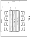
- the meeting room includes a screen 101 along a portion of a first wall thereof that may be utilized as a projector screen for presentations.
- the meeting room also includes a window 103 along a portion of a second wall thereof that provides for viewing of an outside environment located exterior to the meeting room. When present, natural daylight from the outside environment passes through the window 103 and provides lighting to the meeting room.
- the meeting room is eight chairs 105A-H positioned around a rectangular table 107.
- a lighting fixture 120 is present in the meeting room positioned above the rectangular table 107.
- the lighting fixture 120 includes at least one controller 122 in communication with at least one daylight sensor 124 and at least one presence sensor 126.
- the lighting fixture also includes a plurality of task lighting LEDs 130 in communication with the controller 122 and a plurality of face lighting LEDs 140 in communication with the controller 122.
- the task lighting LEDs 130 selectively generate a light output that is directed toward and illuminates at least a portion of the table 107.
- the face lighting LEDs 140 selectively generate a light output that is directed toward and illuminates at least a portion of the area adjacent chairs 105A-D (e.g., at least the area that would be occupied by faces of humans that are sitting in the chairs 105A-D).
- the controller 122 controls the status of task lighting LEDs 130 and face lighting LEDs 140.
- the controller 122 may be in communication with one or more LED drivers powering task lighting LEDs 130 to control whether the task lighting LEDs 130 are generating light output and, if generating light output, to optionally control one or more characteristics of the light output generated by the task lighting LEDs 130.
- the controller 122 may be in communication with one or more LED drivers powering face lighting LEDs 140 to control whether the face lighting LEDs 140 are generating light output and, if generating light output, to optionally control one or more characteristics of the light output generated by the face lighting LEDs 140.
- aspects of the controller 122 may be at least partially integrated in one or more LED drivers powering the LEDs 130 and/or 140.
- the daylight sensor 124 measures one or more values indicative of the daylight level proximal the table 107 and communicates signals indicative of such values to the controller 122.
- the presence sensor 126 measures one or more values indicative of whether a human is present in one or more of the seats 105A-D and communicates signals indicative of such values to the controller 122.
- the daylight sensor 124 may include one or more photosensors.
- the presence sensor 126 may include one or more passive infrared (PIR) sensors in some embodiments.
- the presence sensor 126 may include one or more sensors detecting changes in coded light generated by the lighting fixture 120 (e.g ., change in coded light generated by the face lighting LEDs 140).
- the presence sensor 126 may detect changes in reflected coded light generated by face lighting LEDs 140 when a human is sitting in one of the chairs 105A-D compared to when nobody is sitting in the chairs 105A-D.
- the face lighting LEDs 140 may optionally generate a plurality of coded light transmissions to determine which chair or group of chairs 105A-D is occupied.
- those LEDs of face lighting LEDs 140 generating light output that is directed toward chair 105A may generate a first coded light
- those LEDs of face lighting LEDs 140 generating light output that is directed toward chair 105B may generate a second coded light
- those LEDs of face lighting LEDs 140 generating light output that is directed toward chair 105C may generate a third coded light
- those LEDs of face lighting LEDs 140 generating light output that is directed toward chair 105D may generate a fourth coded light.
- Each coded light may be individually monitored for changes by one or more sensors to determine which of chairs 105A-D are occupied.
- the presence sensor 126 may include one or more video cameras such as an infrared video camera.
- the controller 122, the daylight sensor 124, and the presence sensor 126 may be integrated as a cohesive part of the lighting fixture 120 in some embodiments.
- the daylight sensor 124 may have exposure to the environment exterior of the lighting fixture 120 and face generally toward the table 107 under lighting fixture 120 and/or generally toward the window 103 to enable sensing of light levels proximal the table 107.
- the presence sensor 126 may have exposure to the environment exterior of the lighting fixture 120 and the presence sensor 126 may be directed toward one or more of chairs 105A-D to enable sensing of a human presence in such one or more chairs 105A-D.
- the daylight sensor 124 and/or the presence sensor 126 may be physically separated from other components of the lighting fixture 120.
- the daylight sensor 124 may be placed on the table 107, integrated into the table 107, or placed on a ceiling of the meeting room.
- the presence sensor 126 may be placed in the chairs 105A-D or placed on a ceiling of the meeting room.
- a lighting fixture 110 without a face lighting component is also present in the meeting room positioned above the rectangular table 107.
- the lighting fixture 110 may be controlled independently of the lighting fixture 120.
- the lighting fixture 110 may be manually controlled via a dimming switch.
- the lighting fixture 110 may include its own daylight sensor and adjust its light output dependent on readings from that daylight sensor.
- the lighting fixture 110 and the lighting fixture 120 may be cooperatively controlled.
- the lighting fixtures 110, 120 may be in network communication with one another and may share daylight sensor readings and/or light settings.
- no artificial light is present in the meeting room and the lighting fixture 120 is switched off and the lighting fixture 110 is also switched off.
- This may be the desired state, for example, when nobody is present in the meeting room and/or when a presentation is being presented on the screen 103.
- a user interface e.g., a control panel
- the lighting fixtures 110, 120 may additionally or alternatively be in the state of FIG. 1 in response to no human presence being detected in the room by one or more presence sensors (e.g ., presence sensor 126).
- a task lighting component of the lighting fixture 120 is switched on and the lighting fixture 110 is switched off.
- the task lighting LEDs 130 of the lighting fixture 120 are providing desired illumination to the table 107.
- the daylight sensor 124 may measure the light level on the table 107 (or alternatively may measure the light level elsewhere in the meeting room) and the controller 122 adjust the light output intensity of the task lighting LEDs 130 to maintain the light level at a desired level.
- the light output of one or more of the LEDs 130 may be adjusted based on values from the daylight sensor 124 to maintain the light level on table 107 at approximately 500 lux.
- a user interface e.g ., a control panel
- the controller 122 will automatically place the lighting fixture 120 in the state of FIG. 2 based on readings from presence sensor 126 and/or daylight sensor 124.
- Lighting fixture 110 may additionally or alternatively be illuminated. For example, in some embodiments if lighting fixture 110 is illuminated it may be unnecessary to illuminate task lighting LEDs 130 as brightly and/or to even activate task lighting LEDs 130 at all.
- the task lighting LEDs 130 of the lighting fixture 120 are switched off, the face lighting LEDs 140 of the lighting fixture 120 are switched on, and the lighting fixture 110 is switched off. Desired illumination is being provided to the table 107 via window 103.
- the daylight sensor 124 may measure the light level on the table 107 (or alternatively may measure the light level elsewhere in the meeting room) to enable the controller 122 to determine whether further illumination via task lighting LEDs 130 is required. Also, the daylight sensor 124 may measure the light level on the table 107 to enable the controller 122 to determine when light intensity from window 103 is sufficient to activate face lighting LEDs 140.
- the controller 122 may additionally or alternatively look at the status and characteristics of light output from task lighting LEDs 130 and/or lighting fixture 110 ( e.g., to deduce the contribution from window 103) and/or other daylight sensor ( e.g ., aimed directly at window 103).
- the face lighting LEDs 140 are generating a face light output generally indicated by shaded rectangle 141.
- the face light output is directed toward the area adjacent chairs 105A-D ( e.g ., at least the area that would be occupied by faces of humans that are sitting in the chairs 105A-D). The state of FIG.
- 3 may be the desired state when individuals are sitting in one or more of the chairs 105A-D and daylight is provided through window 103 to an extent that, absent lighting from face lighting LEDs 140, would cause high contrast between entering daylight from the window 103 and the front view of the faces of the individuals sitting in the chairs 105A-D to make viewing of those faces difficult for another individual ( e.g ., an individual in any one of chairs 105E-H).
- the face light output generated by face lighting LEDs 140 may be diffuse to minimize glare to individuals seated in chairs 105A-D.
- the face light output may have a beam angle that restricts the light output generally to areas that would be occupied by the individuals seated in chairs 105A-D. Such a beam angle may enable a substantial portion of the lumen output of the task lighting LEDs 130 to be utilized for illuminating individuals' faces seated in chairs 105A-D.
- only certain of the face lighting LEDs 130 may be illuminated to only provide illumination toward those chairs 105A-D that are actually occupied by a human.
- the light directed at a single of the chairs 105A-D may be directed at multiple portions of a person's face (e.g ., the left side and right side), to increase the modeling of the face (the way the shapes and shadows are visible).
- at least two distinct diffuse face lighting components may be directed toward an individual's face (e.g ., two components primarily directed about two distinct axis spaced apart from one another and/or nonparallel to one another).
- the light output of the face light output may be set as desired.
- the light output intensity of the face light output may be set to achieve approximately 200 lux at a face of an individual sitting in one of the chairs 105A-D.
- the light output intensity of the face light output may be set to achieve a lux value at a face of an individual sitting in one of the chairs 105A-D that is less than or equal to approximately 25% of the lux value at the table 107.
- the controller 122 may utilize input from daylight sensor 124 to adjust the light output intensity of the face lighting LEDs 140 to generate a lux a predetermined distance away that is approximately 20% of the measured lux via daylight sensor 124.
- the light output intensity of the face light output may additionally or alternatively be adjustable (e.g ., from 0% to 25% in an energy savings mode) by a user via a user interface (e.g ., a dimmer) and/or automatically ( e.g ., proportional to brightness of daylight provided through window 103).
- the energy savings mode may be utilized during certain time periods (e.g ., as set by a user via a user interface, during periods of traditionally high energy demand), may be utilized in response to a demand response event communicated to the controller 122, and/or may be utilized as one of a plurality of user selectable modes.
- the light output of the face light output may also be set to a light therapy mode.
- the light output intensity of the face light output may be set to achieve a lux value at a face of an individual sitting in one of the chairs 105A-D that is greater than the light output intensity in the energy savings mode.
- Other light output characteristics of the face light output may additionally or alternatively be altered in therapy mode or energy savings mode such as, for example, color, beam angle, and/or frequency.
- the light therapy mode may be utilized in situations where it is desired to reduce contrast between entering daylight from the window 103 and the front view of the faces of the individuals sitting in the chairs 105A-D to make viewing of those faces less difficult.
- the light therapy mode may be activated without regard to the daylight from the window 103.
- only certain of the face lighting LEDs 130 may be illuminated to only provide illumination toward those chairs 105A-D that are actually occupied by a human. For example, if only chairs 105A and 105D are occupied ( e.g ., as determined by presence sensor 126) then only those LEDs of face lighting LEDs 140 which generate a light output toward chairs 105A and 105D may be illuminated.
- the light output intensity of the face light output may be set to achieve a lux value at a face of an individual sitting in one of the chairs 105A-D that is less than or equal to approximately 200% of the lux value at the table 107.
- the controller 122 may utilize input from daylight sensor 124 to adjust the light output intensity of the face lighting LEDs 140 to generate a lux a predetermined distance away that is approximately 200% of the measured lux via daylight sensor 124.
- the light output intensity of the face light output during the light therapy mode may additionally or alternatively be adjustable ( e.g ., from 0% to 200%) by a user via a user interface ( e.g ., a GUI) and/or automatically.
- the light therapy mode may be utilized during certain time periods (e.g ., as set by a user via a user interface, during periods traditionally utilized for light therapy, at the beginning of a meeting). In some embodiments the light therapy mode may be utilized as one of a plurality of user selectable modes.
- the light therapy mode may be utilized in response to feedback from one or more sensors.
- one or more bio-feedback signals from one or more individuals may be utilized to automatically switch on light therapy mode for the face lighting LEDs directed at those individual(s).
- bio-feedback signals based on an analysis of video images of the eye-movements and/or pupil size may be analyzed. Accordingly, if an individual person sitting at the table is getting less concentrated or sleepy, the face lighting directed at such individual can be altered ( e.g ., switched to one or more higher intensities, switched to one or more different colors - optionally while maintaining face lighting levels directed at other individual(s) at another level ( e.g.
- lighting therapy may otherwise be individually tailored for one or more individuals.
- a user interface may be utilized to set desired light therapy characteristics for certain chairs 105A-D.
- a user may have an RFID tag or other device that communicates desired light therapy settings to the controller 122.
- additional sides of the table 107 may be provided with face lighting if desired.
- face lighting may be provided toward chairs 105E-H and/or toward the chair-less ends of table 107 (where individuals might stand, or sit in additional seating).
- Such additional face lighting may be generated by face lighting LEDs 130 of lighting fixture 120 and/or from one or more additional lighting fixtures having face lighting. Any such additional lighting fixtures may optionally be in network communication with lighting fixture 120.
- FIG. 4 illustrates a side view of the meeting room with the lighting fixtures 110, 120 in a state such as that shown in FIG. 3 .
- the face lighting LEDs 140 of the lighting fixture 120 are directing face light output 106 toward the face of an individual 102 that is seated in chair 105A.
- the face light output 106 makes the face of the individual 102 more easily viewable by those on an opposite side of the table 107 and minimizes the contrast between daylight 104 entering through the window 103 and the front view of the face of the individual 102.
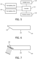
- FIG. 6 illustrates a side view of the lighting fixture 120.
- the task lighting LEDs 130 are provided on a bottom portion of the lighting fixture 120 that generally faces toward the table 107.
- the face lighting LEDs 140 are provided on a side portion of the lighting fixture that is positioned at an upward angle relative to the bottom portion.
- the mounting angle of the LEDs 140 may be selected to direct light output a desired extent peripherally of the lighting fixture 120.
- the LEDs 130 and/or 140 may be paired with one or more reflectors, diffusers, optical pieces, and/or other optical elements to achieve desired light output characteristics.
- FIG. 7 illustrates another embodiment of a lighting fixture 220.
- the lighting fixture 220 includes task lighting LEDs 230 on a bottom portion thereof and a face light component that includes a plurality of LEDs 240 that are mechanically directionally adjustable.
- the directionally adjustable LEDs 240 may enable fine tuning of the illumination to be adaptable to various environments. For example, the direction of the LEDs 240 may be adjusted to accommodate different size tables, to accommodate different lighting fixture installation positions, and/or to accommodate different seating and/or standing arrangements adjacent a table or other task area. In some embodiments, all the LEDs 240 may be uniformly adjustable. In other embodiments individual segments of the LEDs 240 may be individually adjustable. For example, multiple segments may be provided, with each of the segments directed generally toward a user segment such as a chair or group of chairs and each of the segments being individually adjustable.
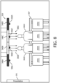
- FIG. 8 illustrates another embodiment of a meeting room having another embodiment of a lighting fixture 320.
- the meeting room includes a presentation screen 201. Inside the meeting room are chairs, four of which (305A-D) are visible and two of which (305B, 305C) have individuals 302B, 302C sitting in them. A window is also present in the meeting room. The window is not illustrated but is to the rear of the two individuals 202B, 202C (in other words, in a direction out of the page). Natural daylight from the outside environment may pass through the window and provide lighting to portions of the meeting room.
- the lighting fixture 320 includes face lighting including a first face lighting segment 340A, a second face lighting segment 340B, a third face lighting segment 340C, and a fourth face lighting segment 340D.
- face lighting including a first face lighting segment 340A, a second face lighting segment 340B, a third face lighting segment 340C, and a fourth face lighting segment 340D.
- Four presence sensors 326A, 326B, 326C, and 326D are also provided, each being paired with a respective of the face lighting segments 340A-D.
- the presence sensor 326A monitors for presence of an individual in seat 305A
- the presence sensor 326B monitors for presence of an individual in seat 305B
- the presence sensor 326C monitors for presence of an individual in seat 305C
- the presence sensor 326D monitors for presence of an individual in seat 305D.
- the lighting segments 340A and 340D are not generating a light output. Since individuals 302B and 302C are present in seats 305A and 305D, lighting segments 340B and 340C are illuminated and directing light output 306B and 306C toward the faces of the individuals 302B, 302C.
- One or more controllers may be in communication with the presence sensors 326A-D and utilize output therefrom to control which face lighting segments 340A-D are illuminated.
- the segments 340A-D may optionally be operable in an energy savings mode and/or a light therapy mode as described herein for example with respect to lighting fixture 120.
- the face lighting segments 340A-D may additionally or alternatively optionally be adjusted and/or activated based at least in part on readings from one or more daylight sensors as described herein for example with respect to lighting fixture 120.
- the lighting fixture 320 may also optionally incorporate a task lighting component including one or more task lighting sources as described herein for example with respect to lighting fixture 120.
Description
- The present invention is directed generally to methods and apparatus for controllable lighting. More particularly, various inventive aspects disclosed herein relate to lighting methods and apparatus having selectively applied face lighting.
- Daylight-responsive lighting systems have been implemented in various environments, such as offices, hotels, and retail stores. The Daylight-responsive lighting systems include one or more light sensors that detect light levels within a lighting environment. The light output of one or more lighting fixtures in the lighting environment is adjusted in response to detected light conditions. For example ,
EP 0 677 697 A1 discloses a ceiling suspended workstation lamp having a built-in brightness sensor which detects the illuminance in the working area within a limited solid angle range, wherein a control of the light source of the workstation light is provided in dependence of the detected illuminance in the work area. For example, it may be desirable to decrease the light output of lighting fixtures when significant natural daylight is provided to the environment, for example via windows or skylights, in order to save energy, provide a more pleasing environment, and/or for other reasons. Also, for example, it may be desirable to increase the light output of lighting fixtures when little or no natural daylight is provided (e.g., at night, cloudy conditions, or when daylight blocking elements such as blinds are utilized) to maintain a desired level of light output in the lighting environment. Although such lighting systems enable adjustment of light output of one or more lighting fixtures that is dependent on daylight conditions, they may have one or more drawbacks. For example, in certain environments (e.g., a meeting room), when daylight is entering the environment and lighting fixtures within the environment are dimmed due to the entering daylight, there is too high of a contrast between the daylight from a bright window and the objects (e.g., humans) that are positioned in front of the window - when those objects are viewed in front of the window. Such high contrast may make viewing of the object positioned in front of the window difficult for a user. For example, only a silhouette of a person positioned in front of a bright window will be visible by a viewer opposite the window and facial expressions will not be fully visible, which may make conversation difficult. - Various therapeutic lighting systems have also been utilized. For example, therapeutic lighting systems have been utilized for therapy for seasonal depression, therapy for jetlag by flying, therapy for social jetlag, etc. Such therapeutic lighting systems often include a lighting fixture that a user must sit or stand in front of for a period of time for therapy purposes. Such therapeutic lighting systems may have one or more drawbacks such as, for example, the requirement of dedicated spaces or locations where the user has to sit down and/or stand for an extended period of time. Also, for example, the bright therapeutic light may be bothersome to other individuals present that do not need the light therapy.
- Thus, there is a need in the art to provide methods and apparatus related to face lighting that may optionally be utilized to overcome one or more drawbacks of existing daylight-responsive lighting systems and/or existing therapeutic lighting systems.
- Applicants have recognized and appreciated that it would be beneficial to provide lighting methods and apparatus having independently adjustable face and task lighting with face lighting being applied selectively. In view of the foregoing, various embodiments and implementations of the present invention are directed to methods and apparatus for controllable lighting.
- For example, methods and apparatus are disclosure that have selectively applied face lighting and, optionally, selectively applied task lighting. The face lighting may be selectively provided to one or more user segments. In some embodiments, the face lighting is only provided to those user segments having a human presence. The face lighting may be provided in a plurality of modes.
- Generally, in one example, a method of controlling a task lighting component and a face lighting component of at least one lighting fixture is provided and includes the steps of: monitoring a light level proximal a task area; providing task lighting from at least one lighting fixture over the task area to the task area when the light level proximal the task area is below a threshold value; monitoring each of a plurality of user segments for a human presence, the user segments adjacent the task area and utilized for user interaction with the task area; and providing face lighting from the at least one lighting fixture over the task area only to the user segments having the human presence.
- In the example, the task lighting is distinct from the face lighting in at least one of intensity, spectral composition, and dynamic behavior. In some versions of those examples, various attributes and characteristics of the face lighting and/or task lighting can be set independently for at least one of the user segments via a user interface.
- In the example, optionally, in response to identifying at least one of a predetermined intensity of incoming daylight and a predetermined direction of the incoming daylight, the face lighting is automatically provided to the user segments that are on the side of the lighting fixture where the daylight originates.
- In the example, optionally, a task lighting level of the task lighting is proportional to the light level proximal the task area.
- In the example, optionally, an origination direction of the face lighting directed toward each of the user segments is adjustable.
- In the example, optionally, an origination direction of the face lighting directed toward each of the user segments includes at least a first component primarily directed about a first axis and a second component primarily directed about a second axis.
- In the example, optionally, the step of monitoring each of the user segments includes monitoring reflections of coded light directed at each of the user segments.
- In the example, optionally, each of the user segments include at least one chair sitting area adjacent the task area.
- In the example, optionally, in a first mode, only the user segments having the human presence and interposed between the task area and a window contributing to the light level are provided with the face lighting. In some versions of the example, in a second mode, all the user segments having the human presence are provided with the face lighting. Optionally, in the first mode, a ratio of a face surface lux to a task surface lux is less than one, the face surface lux taken at a face surface in each of the user segments and the task surface lux taken at the task surface. Optionally, in the second mode, the ratio of the face surface lux to the task surface lux is tunable within a second range, the second range including values greater than one.
- In the example, optionally, the task lighting is generated from a first group of LEDs facing the task area and the face lighting is generated from a second group of LEDs facing the user segments.
- The invention discloses a method of controlling a task lighting component and a face lighting component of at least one lighting fixture, according to
claim 1. The invention discloses a lighting fixture according to claim 12 and a lighting system according to claim 14. Further embodiments are provided by the dependent claims. - The method may further include monitoring each of the user segments for a human presence and providing face lighting only to the user segments having the human presence.
- In some embodiments, in the first mode, the ratio of a face surface lux to a task surface lux is less than one. In some versions of those embodiments, in the second mode, the ratio of the face surface lux to the task surface lux is tunable within a second range, the second range including values greater than one.
- In some embodiments, in the first mode, the ratio of the face surface lux to the task surface lux is less than .5.
- In some embodiments, in the first mode, the ratio of the face surface lux to the task surface lux is tunable from 0 to at least .2.
- In some embodiments, in the second mode, the ratio of the face surface lux to the task surface lux is tunable from 0 to at least 2.
- In still another aspect, the invention focuses on a method of independently controlling a task lighting component and a face lighting component of at least one lighting fixture, wherein said task lighting is distinct from said face lighting in at least one of intensity, spectral composition, and dynamic behavior. The method includes providing task lighting from at least one lighting fixture over said task area to said task area; monitoring at least two of a plurality of user segments for a human presence, said user segments adjacent said task area and utilized for user interaction with said task area; and providing face lighting from said at least one lighting fixture over said task area only to said user segments having said human presence.
- Generally, in yet another aspect, a lighting fixture having a task lighting component and a face lighting component is provided. The lighting fixture includes a plurality of task lighting LEDs selectively providing a task light output in a downward direction below the lighting fixture and a plurality of face lighting LEDs providing a face light output in a direction peripherally of the lighting fixture. The lighting fixture also includes at least one controller controlling the task lighting LEDs and the face lighting LEDs. The controller receives daylight sensing signals and user segment presence sensing signals. The user segment presence sensing signals are indicative of which of a plurality of user segments adjacent a task area are occupied by a human. The controller activates a plurality of the task lighting LEDs when the daylight sensing signals are indicative of a light level below a threshold value. The controller activates a plurality of the face lighting LEDs in a first mode and in a second mode, wherein in the second mode a ratio of a face surface lux to a task surface lux of light output generated by the face lighting LEDs is at least two times greater than it is in the first mode. The controller activates only the face lighting LEDs providing the face lighting output in a direction toward the user segments having the human presence.
- In some embodiments, the lighting fixture further includes at least one daylight sensor providing the daylight sensing signals and at least one presence sensor providing the presence sensing signals.
- As used herein for purposes of the present disclosure, the term "LED" should be understood to include any electroluminescent diode or other type of carrier injection/junction-based system that is capable of generating radiation in response to an electric signal. Thus, the term LED includes, but is not limited to, various semiconductorbased structures that emit light in response to current, light emitting polymers, organic light emitting diodes (OLEDs), electroluminescent strips, and the like. In particular, the term LED refers to light emitting diodes of all types (including semi-conductor and organic light emitting diodes) that may be configured to generate radiation in one or more of the infrared spectrum, ultraviolet spectrum, and various portions of the visible spectrum (generally including radiation wavelengths from approximately 400 nanometers to approximately 700 nanometers). Some examples of LEDs include, but are not limited to, various types of infrared LEDs, ultraviolet LEDs, red LEDs, blue LEDs, green LEDs, yellow LEDs, amber LEDs, orange LEDs, and white LEDs (discussed further below). It also should be appreciated that LEDs may be configured and/or controlled to generate radiation having various bandwidths (e.g., full widths at half maximum, or FWHM) for a given spectrum (e.g., narrow bandwidth, broad bandwidth), and a variety of dominant wavelengths within a given general color categorization.
- For example, one implementation of an LED configured to generate essentially white light (e.g., a white LED) may include a number of dies which respectively emit different spectra of electroluminescence that, in combination, mix to form essentially white light. In another implementation, a white light LED may be associated with a phosphor material that converts electroluminescence having a first spectrum to a different second spectrum. In one example of this implementation, electroluminescence having a relatively short wavelength and narrow bandwidth spectrum "pumps" the phosphor material, which in turn radiates longer wavelength radiation having a somewhat broader spectrum.
- It should also be understood that the term LED does not limit the physical and/or electrical package type of an LED. For example, as discussed above, an LED may refer to a single light emitting device having multiple dies that are configured to respectively emit different spectra of radiation (e.g., that may or may not be individually controllable). Also, an LED may be associated with a phosphor that is considered as an integral part of the LED (e.g., some types of white LEDs). In general, the term LED may refer to packaged LEDs, nonpackaged LEDs, surface mount LEDs, chip-on-board LEDs, T-package mount LEDs, radial package LEDs, power package LEDs, LEDs including some type of encasement and/or optical element (e.g., a diffusing lens), etc.
- The term "light source" should be understood to refer to any one or more of a variety of radiation sources, including, but not limited to, LED-based sources (including one or more LEDs as defined above), incandescent sources (e.g., filament lamps, halogen lamps), fluorescent sources, phosphorescent sources, high-intensity discharge sources (e.g., sodium vapor, mercury vapor, and metal halide lamps), lasers, and other types of electroluminescent sources.
- A given light source may be configured to generate electromagnetic radiation within the visible spectrum, outside the visible spectrum, or a combination of both. Hence, the terms "light" and "radiation" are used interchangeably herein. Additionally, a light source may include as an integral component one or more filters (e.g., color filters), lenses, or other optical components. Also, it should be understood that light sources may be configured for a variety of applications, including, but not limited to, indication, display, and/or illumination. An "illumination source" is a light source that is particularly configured to generate radiation having a sufficient intensity to effectively illuminate an interior or exterior space. In this context, "sufficient intensity" refers to sufficient radiant power in the visible spectrum generated in the space or environment (the unit "lumens" often is employed to represent the total light output from a light source in all directions, in terms of radiant power or "luminous flux") to provide ambient illumination (i.e., light that may be perceived indirectly and that may be, for example, reflected off of one or more of a variety of intervening surfaces before being perceived in whole or in part).
- The terms "spectrum" or "spectral composition" should be understood to refer to any one or more frequencies (or wavelengths) of radiation produced by one or more light sources. Accordingly, the term "spectrum" refers to frequencies (or wavelengths) not only in the visible range, but also frequencies (or wavelengths) in the infrared, ultraviolet, and other areas of the overall electromagnetic spectrum. Also, a given spectrum may have a relatively narrow bandwidth (e.g., a FWHM having essentially few frequency or wavelength components) or a relatively wide bandwidth (several frequency or wavelength components having various relative strengths). It should also be appreciated that a given spectrum may be the result of a
mixing of two or more other spectra (e.g., mixing radiation respectively emitted from multiple light sources). - For purposes of this disclosure, the term "color" is used interchangeably with the terms "spectrum" and "spectral composition." However, the term "color" generally is used to refer primarily to a property of radiation that is perceivable by an observer (although this usage is not intended to limit the scope of this term). Accordingly, the terms "different colors" implicitly refer to multiple spectra having different wavelength components and/or bandwidths. It also should be appreciated that the term "color" may be used in connection with both white and non-white light.
- The term "color temperature" generally is used herein in connection with white light, although this usage is not intended to limit the scope of this term. Color temperature essentially refers to a particular color content or shade (e.g., reddish, bluish) of white light. The color temperature of a given radiation sample conventionally is characterized according to the temperature in degrees Kelvin (K) of a black body radiator that radiates essentially the same spectrum as the radiation sample in question. Black body radiator color temperatures generally fall within a range of from approximately 700 degrees K (typically considered the first visible to the human eye) to over 10,000 degrees K; white light generally is perceived at color temperatures above 1500-2000 degrees K.
- The term "lighting fixture" or "luminaire" are used interchangeably herein to refer to an implementation or arrangement of one or more lighting units in a particular form factor, assembly, or package. The term "lighting unit" is used herein to refer to an apparatus including one or more light sources of same or different types. A given lighting unit may have any one of a variety of mounting arrangements for the light source(s), enclosure/housing arrangements and shapes, and/or electrical and mechanical connection configurations. Additionally, a given lighting unit optionally may be associated with (e.g., include, be coupled to and/or packaged together with) various other components (e.g., control circuitry) relating to the operation of the light source(s). An "LED-based lighting unit" refers to a lighting unit that includes one or more LED-based light sources as discussed above, alone or in combination with other non LED-based light sources. A "multi-channel" lighting unit refers to an LED-based or non LED-based lighting
unit that includes at least two light sources configured to respectively generate different spectrums of radiation, wherein each different source spectrum may be referred to as a "channel" of the multi-channel lighting unit. - The term "controller" is used herein generally to describe various apparatus relating to the operation of one or more light sources. A controller can be implemented in numerous ways (e.g., such as with dedicated hardware) to perform various functions discussed herein. A "processor" is one example of a controller which employs one or more microprocessors that may be programmed using software (e.g., microcode) to perform various functions discussed herein. A controller may be implemented with or without employing a processor, and also may be implemented as a combination of dedicated hardware to perform some functions and a processor (e.g., one or more programmed microprocessors and associated circuitry) to perform other functions. Examples of controller components that may be employed in various embodiments of the present disclosure include, but are not limited to, conventional microprocessors, application specific integrated circuits (ASICs), and field-programmable gate arrays (FPGAs).
- In various implementations, a processor or controller may be associated with one or more storage media (generically referred to herein as "memory," e.g., volatile and nonvolatile computer memory such as RAM, PROM, EPROM, and EEPROM, floppy disks, compact disks, optical disks, magnetic tape, etc.). In some implementations, the storage media may be encoded with one or more programs that, when executed on one or more processors and/or controllers, perform at least some of the functions discussed herein. Various storage media may be fixed within a processor or controller or may be transportable, such that the one or more programs stored thereon can be loaded into a processor or controller so as to implement various aspects of the present invention discussed herein. The terms "program" or "computer program" are used herein in a generic sense to refer to any type of computer code (e.g., software or microcode) that can be employed to program one or more processors or controllers.
- The term "network" as used herein refers to any interconnection of two or more devices (including controllers or processors) that facilitates the transport of information (e.g.
for device control, data storage, data exchange, etc.) between any two or more devices and/or among multiple devices coupled to the network. As should be readily appreciated, various implementations of networks suitable for interconnecting multiple devices may include any of a variety of network topologies and employ any of a variety of communication protocols. Additionally, in various networks according to the present disclosure, any one connection between two devices may represent a dedicated connection between the two systems, or alternatively a non-dedicated connection. In addition to carrying information intended for the two devices, such a non-dedicated connection may carry information not necessarily intended for either of the two devices (e.g., an open network connection). Furthermore, it should be readily appreciated that various networks of devices as discussed herein may employ one or more wireless, wire/cable, and/or fiber optic links to facilitate information transport throughout the network. - The term "user interface" as used herein refers to an interface between a human user or operator and one or more devices that enables communication between the user and the device(s). Examples of user interfaces that may be employed in various implementations of the present disclosure include, but are not limited to, switches, potentiometers, buttons, dials, sliders, a mouse, keyboard, keypad, various types of game controllers (e.g., joysticks), track balls, display screens, various types of graphical user interfaces (GUIs), touch screens, microphones and other types of sensors that may receive some form of human-generated stimulus and generate a signal in response thereto.
- In the drawings, like reference characters generally refer to the same parts throughout the different views. Also, the drawings are not necessarily to scale, emphasis instead generally being placed upon illustrating the principles of the invention.
-
FIG. 1 illustrates a top plan view of a meeting room having an embodiment of a lighting system; no artificial light is present and a lighting fixture with a face light component is switched off and a normal lighting fixture is also switched off. -
FIG. 2 illustrates a top plan view of the meeting room and the first embodiment of the lighting system; a task lighting component of the lighting fixture with the face light component is switched on and the normal lighting fixture is switched off. -
FIG. 3 illustrates a top plan view of the meeting room and the first embodiment of the lighting system; the task lighting component of the lighting fixture with the face light component is switched off, a facial lighting component of the lighting fixture with the face light component is switched on, and the normal lighting fixture is switched off. -
FIG. 4 illustrates a side view of the meeting room; the task lighting component of the lighting fixture with the face light component is switched off, a facial lighting component of the lighting fixture with the face light component is switched on, and the normal lighting fixture is switched off. -
FIG. 5 illustrates a block diagram of the lighting fixture with the face light component of the embodiment of the lighting system ofFIGS. 1-4 . -
FIG. 6 illustrates a side view of the lighting fixture with the face light component of the embodiment of the lighting system ofFIGS. 1-4 . -
FIG. 7 illustrates another embodiment of a lighting fixture with a face light component that is directionally adjustable. -
FIG. 8 illustrates another embodiment of a meeting room having another embodiment of a lighting fixture with a facial lighting component. - In the following detailed description, for purposes of explanation and not limitation, representative embodiments disclosing specific details are set forth in order to provide a
thorough understanding of the claimed invention. Various embodiments of the approach disclosed herein are particularly suited for a lighting system that includes a face lighting component, a task lighting component, and at least one sensor to selectively provide task lighting and selectively provide face lighting in accordance with at least two modes. Accordingly, for illustrative purposes, the claimed invention is discussed in conjunction with such a lighting system. However, other configurations and applications are contemplated. For example, aspects may be implemented in other lighting systems that only include a single mode. Also, for example, aspects may be implemented in other lighting systems that only include a face lighting component. - Referring to
FIGS. 1-3 , a top plan view of a meeting room is illustrated. The meeting room includes ascreen 101 along a portion of a first wall thereof that may be utilized as a projector screen for presentations. The meeting room also includes awindow 103 along a portion of a second wall thereof that provides for viewing of an outside environment located exterior to the meeting room. When present, natural daylight from the outside environment passes through thewindow 103 and provides lighting to the meeting room. Inside the meeting room are eightchairs 105A-H positioned around a rectangular table 107. - A
lighting fixture 120 is present in the meeting room positioned above the rectangular table 107. Referring toFIG. 5 , thelighting fixture 120 includes at least onecontroller 122 in communication with at least onedaylight sensor 124 and at least onepresence sensor 126. The lighting fixture also includes a plurality oftask lighting LEDs 130 in communication with thecontroller 122 and a plurality offace lighting LEDs 140 in communication with thecontroller 122. Thetask lighting LEDs 130 selectively generate a light output that is directed toward and illuminates at least a portion of the table 107. Theface lighting LEDs 140 selectively generate a light output that is directed toward and illuminates at least a portion of the areaadjacent chairs 105A-D (e.g., at least the area that would be occupied by faces of humans that are sitting in thechairs 105A-D). - The
controller 122 controls the status oftask lighting LEDs 130 andface lighting LEDs 140. For example, thecontroller 122 may be in communication with one or more LED drivers poweringtask lighting LEDs 130 to control whether thetask lighting LEDs 130 are generating light output and, if generating light output, to optionally control one or more characteristics of the light output generated by thetask lighting LEDs 130. Also, for example, thecontroller 122 may be in communication with one or more LED drivers poweringface lighting LEDs 140 to control whether theface lighting LEDs 140 are generating light output and, if generating light output, to optionally control one or more characteristics of the light output generated by theface lighting LEDs 140. In some embodiments aspects of thecontroller 122 may be at least partially integrated in one or more LED drivers powering theLEDs 130 and/or 140. - Generally speaking, the
daylight sensor 124 measures one or more values indicative of the daylight level proximal the table 107 and communicates signals indicative of such values to thecontroller 122. Also, generally speaking, thepresence sensor 126 measures one or more values indicative of whether a human is present in one or more of theseats 105A-D and communicates signals indicative of such values to thecontroller 122. Thedaylight sensor 124 may include one or more photosensors. Thepresence sensor 126 may include one or more passive infrared (PIR) sensors in some embodiments. In some embodiments thepresence sensor 126 may include one or more sensors detecting changes in coded light generated by the lighting fixture 120 (e.g., change in coded light generated by the face lighting LEDs 140). For example, thepresence sensor 126 may detect changes in reflected coded light generated byface lighting LEDs 140 when a human is sitting in one of thechairs 105A-D compared to when nobody is sitting in thechairs 105A-D. Theface lighting LEDs 140 may optionally generate a plurality of coded light transmissions to determine which chair or group ofchairs 105A-D is occupied. For example, those LEDs offace lighting LEDs 140 generating light output that is directed towardchair 105A may generate a first coded light, those LEDs offace lighting LEDs 140 generating light output that is directed towardchair 105B may generate a second coded
light, those LEDs offace lighting LEDs 140 generating light output that is directed towardchair 105C may generate a third coded light, and those LEDs offace lighting LEDs 140 generating light output that is directed towardchair 105D may generate a fourth coded light. Each coded light may be individually monitored for changes by one or more sensors to determine which ofchairs 105A-D are occupied. In some embodiment thepresence sensor 126 may include one or more video cameras such as an infrared video camera. - The
controller 122, thedaylight sensor 124, and thepresence sensor 126 may be integrated as a cohesive part of thelighting fixture 120 in some embodiments. For example, thedaylight sensor 124 may have exposure to the environment exterior of thelighting fixture 120 and face generally toward the table 107 underlighting fixture 120 and/or generally toward thewindow 103 to enable sensing of light levels proximal the table 107. Also, for example, thepresence sensor 126 may have exposure to the environment exterior of thelighting fixture 120 and thepresence sensor 126 may be directed toward one or more ofchairs 105A-D to enable sensing of a human presence in such one ormore chairs 105A-D. In other embodiments thedaylight sensor 124 and/or thepresence sensor 126 may be physically separated from other components of thelighting fixture 120. For example, thedaylight sensor 124 may be placed on the table 107, integrated into the table 107, or placed on a ceiling of the meeting room. Also, for example, thepresence sensor 126 may be placed in thechairs 105A-D or placed on a ceiling of the meeting room. One of ordinary skill in the art, having had the benefit of the present disclosure, will recognize and appreciate that various implementations and/or configurations of one or more daylight sensors and/or presence sensor may be utilized to assist in the application of task lighting and/or face lighting from one or more lighting fixtures. - Referring again to
FIGS. 1-3 , alighting fixture 110 without a face lighting component is also present in the meeting room positioned above the rectangular table 107. In some embodiments thelighting fixture 110 may be controlled independently of thelighting fixture 120. For example, in some embodiments thelighting fixture 110 may be manually controlled via a dimming switch. Also, for example, in some embodiments thelighting fixture 110 may include its own daylight sensor and adjust its light output dependent on readings from that daylight sensor. In some other embodiments thelighting fixture 110 and the lighting fixture
120 may be cooperatively controlled. For example, in some embodiment thelighting fixtures - In
FIG. 1 , no artificial light is present in the meeting room and thelighting fixture 120 is switched off and thelighting fixture 110 is also switched off. This may be the desired state, for example, when nobody is present in the meeting room and/or when a presentation is being presented on thescreen 103. A user interface (e.g., a control panel) may be utilized to place thelighting fixtures FIG. 1 . Thelighting fixtures FIG. 1 in response to no human presence being detected in the room by one or more presence sensors (e.g., presence sensor 126). - In
FIG. 2 , a task lighting component of thelighting fixture 120 is switched on and thelighting fixture 110 is switched off. Thetask lighting LEDs 130 of thelighting fixture 120 are providing desired illumination to the table 107. Thedaylight sensor 124 may measure the light level on the table 107 (or alternatively may measure the light level elsewhere in the meeting room) and thecontroller 122 adjust the light output intensity of thetask lighting LEDs 130 to maintain the light level at a desired level. For example, in some embodiments the light output of one or more of theLEDs 130 may be adjusted based on values from thedaylight sensor 124 to maintain the light level on table 107 at approximately 500 lux. The state ofFIG. 2 may be the desired state when individuals are present in the meeting room, task lighting on table 107 is desired, and daylight provided throughwindow 103 alone is insufficient to illuminate the table 107 as desired. A user interface (e.g., a control panel) may optionally be utilized to place thelighting fixtures FIG. 2 . In some embodiments thecontroller 122 will automatically place thelighting fixture 120 in the state ofFIG. 2 based on readings frompresence sensor 126 and/ordaylight sensor 124.Lighting fixture 110 may additionally or alternatively be illuminated. For example, in some embodiments iflighting fixture 110 is illuminated it may be unnecessary to illuminatetask lighting LEDs 130 as brightly and/or to even activatetask lighting LEDs 130 at all. - In
FIG. 3 , thetask lighting LEDs 130 of thelighting fixture 120 are switched off, theface lighting LEDs 140 of thelighting fixture 120 are switched on, and thelighting fixture 110 is
switched off. Desired illumination is being provided to the table 107 viawindow 103. Thedaylight sensor 124 may measure the light level on the table 107 (or alternatively may measure the light level elsewhere in the meeting room) to enable thecontroller 122 to determine whether further illumination viatask lighting LEDs 130 is required. Also, thedaylight sensor 124 may measure the light level on the table 107 to enable thecontroller 122 to determine when light intensity fromwindow 103 is sufficient to activateface lighting LEDs 140. Thecontroller 122 may additionally or alternatively look at the status and characteristics of light output fromtask lighting LEDs 130 and/or lighting fixture 110 (e.g., to deduce the contribution from window 103) and/or other daylight sensor (e.g., aimed directly at window 103). Theface lighting LEDs 140 are generating a face light output generally indicated byshaded rectangle 141. The face light output is directed toward the areaadjacent chairs 105A-D (e.g., at least the area that would be occupied by faces of humans that are sitting in thechairs 105A-D). The state ofFIG. 3 may be the desired state when individuals are sitting in one or more of thechairs 105A-D and daylight is provided throughwindow 103 to an extent that, absent lighting fromface lighting LEDs 140, would cause high contrast between entering daylight from thewindow 103 and the front view of the faces of the individuals sitting in thechairs 105A-D to make viewing of those faces difficult for another individual (e.g., an individual in any one ofchairs 105E-H). - The face light output generated by
face lighting LEDs 140 may be diffuse to minimize glare to individuals seated inchairs 105A-D. In some embodiments the face light output may have a beam angle that restricts the light output generally to areas that would be occupied by the individuals seated inchairs 105A-D. Such a beam angle may enable a substantial portion of the lumen output of thetask lighting LEDs 130 to be utilized for illuminating individuals' faces seated inchairs 105A-D. In some embodiments only certain of theface lighting LEDs 130 may be illuminated to only provide illumination toward thosechairs 105A-D that are actually occupied by a human. For example, if only chairs 105A and 105D are occupied (e.g., as determined by presence sensor 126) then only those LEDs offace lighting LEDs 130 which generate a light output towardchairs chairs 105A-D may be directed at multiple
portions of a person's face (e.g., the left side and right side), to increase the modeling of the face (the way the shapes and shadows are visible). For example, at least two distinct diffuse face lighting components may be directed toward an individual's face (e.g., two components primarily directed about two distinct axis spaced apart from one another and/or nonparallel to one another). - The light output of the face light output may be set as desired. For example, in some embodiments the light output intensity of the face light output may be set to achieve approximately 200 lux at a face of an individual sitting in one of the
chairs 105A-D. Also, for example, in some embodiments, during an energy savings mode the light output intensity of the face light output may be set to achieve a lux value at a face of an individual sitting in one of thechairs 105A-D that is less than or equal to approximately 25% of the lux value at the table 107. For example, thecontroller 122 may utilize input fromdaylight sensor 124 to adjust the light output intensity of theface lighting LEDs 140 to generate a lux a predetermined distance away that is approximately 20% of the measured lux viadaylight sensor 124. In some embodiments the light output intensity of the face light output may additionally or alternatively be adjustable (e.g., from 0% to 25% in an energy savings mode) by a user via a user interface (e.g., a dimmer) and/or automatically (e.g., proportional to brightness of daylight provided through window 103). In some embodiments the energy savings mode may be utilized during certain time periods (e.g., as set by a user via a user interface, during periods of traditionally high energy demand), may be utilized in response to a demand response event communicated to thecontroller 122, and/or may be utilized as one of a plurality of user selectable modes. - In some embodiments, the light output of the face light output may also be set to a light therapy mode. During the light therapy mode the light output intensity of the face light output may be set to achieve a lux value at a face of an individual sitting in one of the
chairs 105A-D that is greater than the light output intensity in the energy savings mode. Other light output characteristics of the face light output may additionally or alternatively be altered in therapy mode or energy savings mode such as, for example, color, beam angle, and/or frequency. In some embodiments the light therapy mode may be utilized in situations where it is desired to reduce contrast between entering daylight from thewindow 103 and the front
view of the faces of the individuals sitting in thechairs 105A-D to make viewing of those faces less difficult. In some embodiments the light therapy mode may be activated without regard to the daylight from thewindow 103. In some embodiments, during light therapy mode, only certain of theface lighting LEDs 130 may be illuminated to only provide illumination toward thosechairs 105A-D that are actually occupied by a human. For example, if only chairs 105A and 105D are occupied (e.g., as determined by presence sensor 126) then only those LEDs offace lighting LEDs 140 which generate a light output towardchairs - In some embodiments, during light therapy mode the light output intensity of the face light output may be set to achieve a lux value at a face of an individual sitting in one of the
chairs 105A-D that is less than or equal to approximately 200% of the lux value at the table 107. For example, thecontroller 122 may utilize input fromdaylight sensor 124 to adjust the light output intensity of theface lighting LEDs 140 to generate a lux a predetermined distance away that is approximately 200% of the measured lux viadaylight sensor 124. In some embodiments the light output intensity of the face light output during the light therapy mode may additionally or alternatively be adjustable (e.g., from 0% to 200%) by a user via a user interface (e.g., a GUI) and/or automatically. In some embodiments the light therapy mode may be utilized during certain time periods (e.g., as set by a user via a user interface, during periods traditionally utilized for light therapy, at the beginning of a meeting). In some embodiments the light therapy mode may be utilized as one of a plurality of user selectable modes. - In some embodiments, the light therapy mode may be utilized in response to feedback from one or more sensors. For example, one or more bio-feedback signals from one or more individuals may be utilized to automatically switch on light therapy mode for the face lighting LEDs directed at those individual(s). For example, bio-feedback signals based on an analysis of video images of the eye-movements and/or pupil size may be analyzed. Accordingly, if an individual person sitting at the table is getting less concentrated or sleepy, the face lighting directed at such individual can be altered (e.g., switched to one or more higher intensities, switched to one or more different colors - optionally while maintaining face lighting levels directed at other individual(s) at another level (e.g., a different light therapy mode level, an
energy savings mode level, or off completely)). In some embodiments lighting therapy may otherwise be individually tailored for one or more individuals. For example, in some embodiments a user interface may be utilized to set desired light therapy characteristics forcertain chairs 105A-D. Also, for example, a user may have an RFID tag or other device that communicates desired light therapy settings to thecontroller 122. - Although only one side of the table 107 is provided with face lighting from
face lighting LEDs 140 in the Figures, in other embodiments additional sides of the table 107 may be provided with face lighting if desired. For example, in some embodiments face lighting may be provided towardchairs 105E-H and/or toward the chair-less ends of table 107 (where individuals might stand, or sit in additional seating). Such additional face lighting may be generated byface lighting LEDs 130 oflighting fixture 120 and/or from one or more additional lighting fixtures having face lighting. Any such additional lighting fixtures may optionally be in network communication withlighting fixture 120. -
FIG. 4 illustrates a side view of the meeting room with thelighting fixtures FIG. 3 . Theface lighting LEDs 140 of thelighting fixture 120 are directing facelight output 106 toward the face of an individual 102 that is seated inchair 105A. The facelight output 106 makes the face of the individual 102 more easily viewable by those on an opposite side of the table 107 and minimizes the contrast betweendaylight 104 entering through thewindow 103 and the front view of the face of the individual 102. -
FIG. 6 illustrates a side view of thelighting fixture 120. Thetask lighting LEDs 130 are provided on a bottom portion of thelighting fixture 120 that generally faces toward the table 107. Theface lighting LEDs 140 are provided on a side portion of the lighting fixture that is positioned at an upward angle relative to the bottom portion. In some embodiments the mounting angle of theLEDs 140 may be selected to direct light output a desired extent peripherally of thelighting fixture 120. TheLEDs 130 and/or 140 may be paired with one or more reflectors, diffusers, optical pieces, and/or other optical elements to achieve desired light output characteristics. -
FIG. 7 illustrates another embodiment of alighting fixture 220. Thelighting fixture 220 includestask lighting LEDs 230 on a bottom portion thereof and a face light component that includes a plurality ofLEDs 240 that are mechanically directionally adjustable. The directionallyadjustable LEDs 240 may enable fine tuning of the illumination to be adaptable to various environments. For example, the direction of theLEDs 240 may be adjusted to accommodate different size tables, to accommodate different lighting fixture installation positions, and/or to accommodate different seating and/or standing arrangements adjacent a table or other task area. In some embodiments, all theLEDs 240 may be uniformly adjustable. In other embodiments individual segments of theLEDs 240 may be individually adjustable. For example, multiple segments may be provided, with each of the segments directed generally toward a user segment such as a chair or group of chairs and each of the segments being individually adjustable. -
FIG. 8 illustrates another embodiment of a meeting room having another embodiment of alighting fixture 320. The meeting room includes a presentation screen 201. Inside the meeting room are chairs, four of which (305A-D) are visible and two of which (305B, 305C) haveindividuals - The
lighting fixture 320 includes face lighting including a firstface lighting segment 340A, a secondface lighting segment 340B, a thirdface lighting segment 340C, and a fourthface lighting segment 340D. Fourpresence sensors face lighting segments 340A-D. Thepresence sensor 326A monitors for presence of an individual inseat 305A, thepresence sensor 326B monitors for presence of an individual inseat 305B, thepresence sensor 326C monitors for presence of an individual inseat 305C, and thepresence sensor 326D monitors for presence of an individual inseat 305D. Since nobody is present inseats lighting segments individuals
are present inseats lighting segments light output individuals - One or more controllers may be in communication with the
presence sensors 326A-D and utilize output therefrom to control which facelighting segments 340A-D are illuminated. Thesegments 340A-D may optionally be operable in an energy savings mode and/or a light therapy mode as described herein for example with respect tolighting fixture 120. Theface lighting segments 340A-D may additionally or alternatively optionally be adjusted and/or activated based at least in part on readings from one or more daylight sensors as described herein for example with respect tolighting fixture 120. Thelighting fixture 320 may also optionally incorporate a task lighting component including one or more task lighting sources as described herein for example with respect tolighting fixture 120.
Claims (14)
- A method of controlling a task lighting component (130, 230) and a face lighting component (140, 240, 340A...D) of at least one lighting fixture (120, 220, 320), comprising:monitoring a light level proximal a task area;providing task lighting from at least one lighting fixture over said task area to said task area when said light level proximal said task area is below a threshold value;characterized in comprisingmonitoring each of a plurality of user segments for human presence, said user segments being adjacent to said task area and utilized for user interaction with said task area; andproviding face lighting from said at least one lighting fixture over said task area only to said user segment having said human presence;wherein said face lighting and task lighting are independently adjustable such that the task lighting is distinct from the face lighting in at least one of intensity, spectral composition, and dynamic behavior.
- The method of claim 1, wherein said task lighting is distinct from said face lighting in at least one of intensity, spectral composition, and dynamic behavior.
- The method of claim 2, wherein said characteristics of said face lighting can be set independently for at least one of said user segments via a user interface.
- The method of any of the preceding claims, wherein, in response to identifying at least one of a predetermined intensity of incoming daylight and a predetermined direction of said incoming daylight, said face lighting is automatically provided to said user segments that are on the side of said lighting fixture where said daylight originates.
- The method of any of the preceding claims, wherein a task lighting level of said task lighting is proportional to said light level proximate to said task area.
- The method of any of the preceding claims, wherein an origination direction of said face lighting directed toward each of said user segments is adjustable.
- The method of any of the preceding claims, wherein said step of monitoring each of said user segments includes monitoring reflections of coded light directed at each of said user segments.
- The method of any of the preceding claims, wherein in a first mode, only said user segments having said human presence and interposed between said task area and a window contributing to said light level are provided with said face lighting.
- The method of claim 8, wherein in a second mode, all said user segments having said human presence are provided with said face lighting.
- The method of claim 9, wherein in said first mode, a ratio of a face surface lux to a task surface lux is less than one, said face surface lux taken at a face surface in each of said user segments and said task surface lux taken at said task surface, and wherein in said second mode, said ratio of said face surface lux to said task surface lux is tunable within a second range, said second range including values greater than one.
- The method of claim 2, wherein the at least one of intensity, spectral composition and dynamic behavior of said face lighting and said task lighting that are adjustable independently from each other are selected from the group consisting of: intensity, spectral composition, and dynamic behavior.
- A lighting fixture (120) comprising:a task lighting component (130, 230) comprising a plurality of task lighting LEDs selectively providing a task light output in a downward direction below the lighting fixture (120);a face lighting component (140, 240, 340A...D) comprising a plurality of face lighting LEDs providing a face light output in a direction peripherally of the lighting fixture; andat least one controller (122) configured to receive daylight sensing signals and user segment presence sensing signals, wherein the user segment presence sensing signals are indicative of which of a plurality of user segments adjacent a task area are occupied by a human, the at least one controller (122) configured to activate a plurality of the task lighting LEDs when the daylight sensing signals are indicative of a light level below a threshold value and activate only the face lighting LEDs providing the face lighting output in a direction toward the user segments having the human presence.
- The lighting fixture (120) according to claim 12 further comprising at least one daylight sensor (124) for providing the daylight sensor signals and at least one presence sensor (126) for providing the user presence sensor signals.
- A lighting system comprising at least one lighting fixture (120, 220, 320) according to claim 12 and at least one daylight sensor (124) for providing the daylight sensor signals and at least one presence sensor (126) for providing the user presence sensor signals.
Applications Claiming Priority (2)
| Application Number | Priority Date | Filing Date | Title |
|---|---|---|---|
| US201261622596P | 2012-04-11 | 2012-04-11 | |
| PCT/IB2013/052735 WO2013153495A1 (en) | 2012-04-11 | 2013-04-05 | Lighting methods and apparatus with selectively applied face lighting component |
Publications (2)
| Publication Number | Publication Date |
|---|---|
| EP2837271A1 EP2837271A1 (en) | 2015-02-18 |
| EP2837271B1 true EP2837271B1 (en) | 2024-03-06 |
Family
ID=48579142
Family Applications (1)
| Application Number | Title | Priority Date | Filing Date |
|---|---|---|---|
| EP13727975.8A Active EP2837271B1 (en) | 2012-04-11 | 2013-04-05 | Lighting methods and apparatus with selectively applied face lighting component |
Country Status (6)
| Country | Link |
|---|---|
| US (2) | US9392651B2 (en) |
| EP (1) | EP2837271B1 (en) |
| JP (1) | JP6173432B2 (en) |
| CN (1) | CN104206025B (en) |
| RU (1) | RU2627029C2 (en) |
| WO (1) | WO2013153495A1 (en) |
Families Citing this family (19)
| Publication number | Priority date | Publication date | Assignee | Title |
|---|---|---|---|---|
| US10813199B2 (en) * | 2012-02-07 | 2020-10-20 | Dolan Designs Incorporated | Combined lighting device with an integrated dimming control system |
| JP6339088B2 (en) * | 2012-10-26 | 2018-06-06 | フィリップス ライティング ホールディング ビー ヴィ | Lighting method for giving individual lighting to users located close to each other |
| US9992841B2 (en) * | 2013-04-19 | 2018-06-05 | Lutron Electronics Co., Inc. | Systems and methods for controlling color temperature |
| US9188307B2 (en) * | 2013-12-17 | 2015-11-17 | Ephesus Lighting, Inc. | High intensity LED illumination device with automated sensor-based control |
| DE102014207632A1 (en) * | 2014-04-23 | 2015-10-29 | Zumtobel Lighting Gmbh | Arrangement and method for illuminating workspaces |
| US9678494B2 (en) * | 2015-04-02 | 2017-06-13 | Elwha Llc | Systems and methods for controlling lighting based on a display |
| US9681525B2 (en) * | 2015-04-02 | 2017-06-13 | Elwha Llc | Systems and methods for controlling lighting based on a display |
| US10185205B2 (en) * | 2015-07-13 | 2019-01-22 | The Regents Of The University Of Colorado, A Body | CMOS compatible optical modulators |
| DE202016100586U1 (en) * | 2016-02-05 | 2017-05-10 | Zumtobel Lighting Gmbh | Trunking system with several controllable light band modules |
| EP3337297A1 (en) * | 2016-12-15 | 2018-06-20 | Thomson Licensing | Apparatus and method for controlling lighting conditions in a room |
| DE102017205449A1 (en) * | 2017-03-30 | 2018-10-04 | Zumtobel Lighting Gmbh | lamp |
| US11314214B2 (en) | 2017-09-15 | 2022-04-26 | Kohler Co. | Geographic analysis of water conditions |
| US10887125B2 (en) * | 2017-09-15 | 2021-01-05 | Kohler Co. | Bathroom speaker |
| US11093554B2 (en) | 2017-09-15 | 2021-08-17 | Kohler Co. | Feedback for water consuming appliance |
| US11099540B2 (en) | 2017-09-15 | 2021-08-24 | Kohler Co. | User identity in household appliances |
| WO2019068665A1 (en) | 2017-10-05 | 2019-04-11 | Signify Holding B.V. | Circadian lighting arrangement |
| WO2019105880A1 (en) * | 2017-11-28 | 2019-06-06 | Signify Holding B.V. | Lighting fixture design |
| CN108156707B (en) * | 2017-12-25 | 2020-04-24 | 安徽极光照明工程有限公司 | LED reading lamp device system based on sensing monitoring control |
| JP2022151862A (en) * | 2021-03-25 | 2022-10-07 | 國立陽明交通大學 | Ambient lighting to improve sleep disturbances, cognitive and/or neurological deficits |
Family Cites Families (26)
| Publication number | Priority date | Publication date | Assignee | Title |
|---|---|---|---|---|
| JP2866774B2 (en) * | 1992-11-09 | 1999-03-08 | 株式会社東海理化電機製作所 | Object detection device |
| DE4413070A1 (en) | 1994-04-15 | 1995-10-19 | Thorn Licht Gmbh | Workplace lamp |
| US20040052076A1 (en) * | 1997-08-26 | 2004-03-18 | Mueller George G. | Controlled lighting methods and apparatus |
| JP3788099B2 (en) * | 1999-03-31 | 2006-06-21 | 三菱電機株式会社 | Lighting system |
| US6665805B1 (en) * | 1999-12-27 | 2003-12-16 | Intel Corporation | Method and apparatus for real time monitoring of user presence to prolong a portable computer battery operation time |
| EP1568256A1 (en) * | 2002-11-22 | 2005-08-31 | Koninklijke Philips Electronics N.V. | System for and method of controlling a light source and lighting arrangement |
| RU2325047C1 (en) * | 2004-02-02 | 2008-05-20 | Ботем Электроник Ко., Лтд. | Low-power switch |
| ES2804755T3 (en) * | 2004-10-05 | 2021-02-09 | Signify Holding Bv | Interactive lighting system |
| US8042967B2 (en) | 2006-01-16 | 2011-10-25 | Koninklijke Philips Electronics N.V. | Lamp module and lighting device comprising such a lamp module |
| JP2008005416A (en) | 2006-06-26 | 2008-01-10 | Toshiba Corp | Signal synthesizer, signal transmitter, and signal receiver |
| TWI334037B (en) * | 2006-09-04 | 2010-12-01 | Ind Tech Res Inst | Electro-optical modulator with curving resonantor |
| KR101500969B1 (en) | 2007-04-17 | 2015-03-10 | 코닌클리케 필립스 엔.브이. | Beam-shaping device |
| JP5542658B2 (en) * | 2007-05-04 | 2014-07-09 | コーニンクレッカ フィリップス エヌ ヴェ | LED-type luminaire and related method for temperature management |
| RU2010100956A (en) * | 2007-06-14 | 2011-07-20 | Конинклейке Филипс Электроникс Н.В. (Nl) | METHOD, SYSTEM, LABEL AND DEVICE OF USER OBJECT LOCALIZATION INTERFACE |
| FR2928809B1 (en) * | 2008-03-17 | 2012-06-29 | Antoine Doublet | INTERACTIVE SYSTEM AND METHOD FOR CONTROLLING LIGHTING AND / OR IMAGE BROADCAST |
| EP2274957A4 (en) * | 2008-04-14 | 2012-09-26 | Digital Lumens Inc | Modular lighting systems |
| JP2010123534A (en) | 2008-11-21 | 2010-06-03 | Panasonic Electric Works Co Ltd | Illumination system |
| JP4621779B2 (en) | 2009-02-17 | 2011-01-26 | シャープ株式会社 | LIGHTING DEVICE AND LIGHTING DEVICE USING THE LIGHTING DEVICE |
| JP5486205B2 (en) | 2009-03-26 | 2014-05-07 | パナソニック株式会社 | Illumination method using task lighting apparatus and task lighting apparatus |
| JP5433291B2 (en) * | 2009-04-24 | 2014-03-05 | パナソニック株式会社 | Task ambient lighting system |
| CN101711079B (en) * | 2009-11-24 | 2013-10-23 | 江苏大学 | Classroom illumination wireless detection and control device and method |
| US20110270446A1 (en) * | 2010-05-03 | 2011-11-03 | Energy Eye, Inc. | Systems and methods for an environmental control system including a motorized vent covering |
| CN104185935B (en) * | 2012-03-28 | 2017-03-15 | 皇家飞利浦有限公司 | For the method and apparatus for operating lighting mains according to energy requirement and energy supply |
| US8779669B2 (en) * | 2012-08-24 | 2014-07-15 | Abl Ip Holding Llc | Chaotic approach to control of lighting |
| JP6339088B2 (en) * | 2012-10-26 | 2018-06-06 | フィリップス ライティング ホールディング ビー ヴィ | Lighting method for giving individual lighting to users located close to each other |
| WO2014115048A1 (en) * | 2013-01-25 | 2014-07-31 | Koninklijke Philips N.V. | Lighting device and lighting system |
-
2013
- 2013-04-05 CN CN201380019272.XA patent/CN104206025B/en active Active
- 2013-04-05 RU RU2014145198A patent/RU2627029C2/en active
- 2013-04-05 WO PCT/IB2013/052735 patent/WO2013153495A1/en active Application Filing
- 2013-04-05 EP EP13727975.8A patent/EP2837271B1/en active Active
- 2013-04-05 JP JP2015505045A patent/JP6173432B2/en active Active
- 2013-04-05 US US14/391,287 patent/US9392651B2/en active Active
- 2013-04-11 US US13/860,978 patent/US8947764B1/en active Active
Also Published As
| Publication number | Publication date |
|---|---|
| EP2837271A1 (en) | 2015-02-18 |
| CN104206025B (en) | 2017-08-08 |
| RU2627029C2 (en) | 2017-08-03 |
| RU2014145198A (en) | 2016-05-27 |
| US9392651B2 (en) | 2016-07-12 |
| JP2015516657A (en) | 2015-06-11 |
| JP6173432B2 (en) | 2017-08-02 |
| CN104206025A (en) | 2014-12-10 |
| US8947764B1 (en) | 2015-02-03 |
| WO2013153495A1 (en) | 2013-10-17 |
| US20150061506A1 (en) | 2015-03-05 |
Similar Documents
| Publication | Publication Date | Title |
|---|---|---|
| EP2837271B1 (en) | Lighting methods and apparatus with selectively applied face lighting component | |
| EP2912925B1 (en) | Lighting methods for providing personalized lighting to users positioned proximal to one another | |
| EP2874701B1 (en) | Methods and apparatus for providing personalized lighting | |
| US10598363B2 (en) | Apparatus and method for providing downlighting and wall-washing lighting effects | |
| EP3162170B1 (en) | Automatically commissioning a group of lighting units | |
| JP6688222B2 (en) | Lighting unit and associated method for providing reduced intensity light output based on user proximity | |
| US11441749B2 (en) | Lighting assembly for electrically adjustable light distributions | |
| JP6291142B2 (en) | Lighting control based on one or more lengths of flexible substrate | |
| CN113424661A (en) | Lighting system with constant illuminance dimming | |
| EP2779792A1 (en) | Luminaire, and luminaire control method | |
| JP5433291B2 (en) | Task ambient lighting system | |
| US20180259143A1 (en) | Methods, systems and apparatus for emergency lighting | |
| US20160295672A1 (en) | Method and system for providing a dynamic lighting effect to specular and refractive objects |
Legal Events
| Date | Code | Title | Description |
|---|---|---|---|
| PUAI | Public reference made under article 153(3) epc to a published international application that has entered the european phase |
Free format text: ORIGINAL CODE: 0009012 |
|
| 17P | Request for examination filed |
Effective date: 20141111 |
|
| AK | Designated contracting states |
Kind code of ref document: A1 Designated state(s): AL AT BE BG CH CY CZ DE DK EE ES FI FR GB GR HR HU IE IS IT LI LT LU LV MC MK MT NL NO PL PT RO RS SE SI SK SM TR |
|
| AX | Request for extension of the european patent |
Extension state: BA ME |
|
| DAX | Request for extension of the european patent (deleted) | ||
| RAP1 | Party data changed (applicant data changed or rights of an application transferred) |
Owner name: PHILIPS LIGHTING HOLDING B.V. |
|
| RIN1 | Information on inventor provided before grant (corrected) |
Inventor name: SCHLANGEN, LUCAS JOSEF MARIA Inventor name: VAN DER POEL, LUCAS LEO DESIREE Inventor name: BAAIJENS, JOHANNES PETRUS WILHELMUS |
|
| RAP1 | Party data changed (applicant data changed or rights of an application transferred) |
Owner name: PHILIPS LIGHTING HOLDING B.V. |
|
| RAP1 | Party data changed (applicant data changed or rights of an application transferred) |
Owner name: SIGNIFY HOLDING B.V. |
|
| STAA | Information on the status of an ep patent application or granted ep patent |
Free format text: STATUS: EXAMINATION IS IN PROGRESS |
|
| 17Q | First examination report despatched |
Effective date: 20190514 |
|
| STAA | Information on the status of an ep patent application or granted ep patent |
Free format text: STATUS: EXAMINATION IS IN PROGRESS |
|
| STAA | Information on the status of an ep patent application or granted ep patent |
Free format text: STATUS: EXAMINATION IS IN PROGRESS |
|
| REG | Reference to a national code |
Ref country code: DE Ref legal event code: R079 Free format text: PREVIOUS MAIN CLASS: H05B0037020000 Ipc: H05B0047110000 Ref country code: DE Ref legal event code: R079 Ref document number: 602013085392 Country of ref document: DE Free format text: PREVIOUS MAIN CLASS: H05B0037020000 Ipc: H05B0047110000 |
|
| GRAP | Despatch of communication of intention to grant a patent |
Free format text: ORIGINAL CODE: EPIDOSNIGR1 |
|
| STAA | Information on the status of an ep patent application or granted ep patent |
Free format text: STATUS: GRANT OF PATENT IS INTENDED |
|
| INTG | Intention to grant announced |
Effective date: 20230721 |
|
| RIC1 | Information provided on ipc code assigned before grant |
Ipc: H05B 47/115 20200101ALN20230710BHEP Ipc: H05B 47/11 20200101AFI20230710BHEP |
|
| GRAJ | Information related to disapproval of communication of intention to grant by the applicant or resumption of examination proceedings by the epo deleted |
Free format text: ORIGINAL CODE: EPIDOSDIGR1 |
|
| STAA | Information on the status of an ep patent application or granted ep patent |
Free format text: STATUS: EXAMINATION IS IN PROGRESS |
|
| GRAP | Despatch of communication of intention to grant a patent |
Free format text: ORIGINAL CODE: EPIDOSNIGR1 |
|
| STAA | Information on the status of an ep patent application or granted ep patent |
Free format text: STATUS: GRANT OF PATENT IS INTENDED |
|
| INTC | Intention to grant announced (deleted) | ||
| RIC1 | Information provided on ipc code assigned before grant |
Ipc: H05B 47/115 20200101ALN20230920BHEP Ipc: H05B 47/11 20200101AFI20230920BHEP |
|
| INTG | Intention to grant announced |
Effective date: 20231010 |
|
| GRAS | Grant fee paid |
Free format text: ORIGINAL CODE: EPIDOSNIGR3 |
|
| GRAA | (expected) grant |
Free format text: ORIGINAL CODE: 0009210 |
|
| STAA | Information on the status of an ep patent application or granted ep patent |
Free format text: STATUS: THE PATENT HAS BEEN GRANTED |
|
| AK | Designated contracting states |
Kind code of ref document: B1 Designated state(s): AL AT BE BG CH CY CZ DE DK EE ES FI FR GB GR HR HU IE IS IT LI LT LU LV MC MK MT NL NO PL PT RO RS SE SI SK SM TR |
|
| P01 | Opt-out of the competence of the unified patent court (upc) registered |
Effective date: 20240130 |
|
| REG | Reference to a national code |
Ref country code: GB Ref legal event code: FG4D |
|
| REG | Reference to a national code |
Ref country code: CH Ref legal event code: EP |
|
| REG | Reference to a national code |
Ref country code: DE Ref legal event code: R096 Ref document number: 602013085392 Country of ref document: DE |
|
| REG | Reference to a national code |
Ref country code: IE Ref legal event code: FG4D |