EP2836879B1 - Control device for a hydraulic cylinder unit with single valve control - Google Patents
Control device for a hydraulic cylinder unit with single valve control Download PDFInfo
- Publication number
- EP2836879B1 EP2836879B1 EP13722706.2A EP13722706A EP2836879B1 EP 2836879 B1 EP2836879 B1 EP 2836879B1 EP 13722706 A EP13722706 A EP 13722706A EP 2836879 B1 EP2836879 B1 EP 2836879B1
- Authority
- EP
- European Patent Office
- Prior art keywords
- control device
- linearisation
- piston
- unit
- factors
- Prior art date
- Legal status (The legal status is an assumption and is not a legal conclusion. Google has not performed a legal analysis and makes no representation as to the accuracy of the status listed.)
- Not-in-force
Links
Images


Classifications
-
- F—MECHANICAL ENGINEERING; LIGHTING; HEATING; WEAPONS; BLASTING
- F15—FLUID-PRESSURE ACTUATORS; HYDRAULICS OR PNEUMATICS IN GENERAL
- F15B—SYSTEMS ACTING BY MEANS OF FLUIDS IN GENERAL; FLUID-PRESSURE ACTUATORS, e.g. SERVOMOTORS; DETAILS OF FLUID-PRESSURE SYSTEMS, NOT OTHERWISE PROVIDED FOR
- F15B9/00—Servomotors with follow-up action, e.g. obtained by feed-back control, i.e. in which the position of the actuated member conforms with that of the controlling member
- F15B9/02—Servomotors with follow-up action, e.g. obtained by feed-back control, i.e. in which the position of the actuated member conforms with that of the controlling member with servomotors of the reciprocatable or oscillatable type
- F15B9/08—Servomotors with follow-up action, e.g. obtained by feed-back control, i.e. in which the position of the actuated member conforms with that of the controlling member with servomotors of the reciprocatable or oscillatable type controlled by valves affecting the fluid feed or the fluid outlet of the servomotor
- F15B9/09—Servomotors with follow-up action, e.g. obtained by feed-back control, i.e. in which the position of the actuated member conforms with that of the controlling member with servomotors of the reciprocatable or oscillatable type controlled by valves affecting the fluid feed or the fluid outlet of the servomotor with electrical control means
-
- G—PHYSICS
- G05—CONTROLLING; REGULATING
- G05B—CONTROL OR REGULATING SYSTEMS IN GENERAL; FUNCTIONAL ELEMENTS OF SUCH SYSTEMS; MONITORING OR TESTING ARRANGEMENTS FOR SUCH SYSTEMS OR ELEMENTS
- G05B11/00—Automatic controllers
- G05B11/01—Automatic controllers electric
- G05B11/36—Automatic controllers electric with provision for obtaining particular characteristics, e.g. proportional, integral, differential
- G05B11/38—Automatic controllers electric with provision for obtaining particular characteristics, e.g. proportional, integral, differential for obtaining a proportional characteristic
-
- G—PHYSICS
- G05—CONTROLLING; REGULATING
- G05B—CONTROL OR REGULATING SYSTEMS IN GENERAL; FUNCTIONAL ELEMENTS OF SUCH SYSTEMS; MONITORING OR TESTING ARRANGEMENTS FOR SUCH SYSTEMS OR ELEMENTS
- G05B15/00—Systems controlled by a computer
- G05B15/02—Systems controlled by a computer electric
-
- G—PHYSICS
- G05—CONTROLLING; REGULATING
- G05D—SYSTEMS FOR CONTROLLING OR REGULATING NON-ELECTRIC VARIABLES
- G05D7/00—Control of flow
- G05D7/06—Control of flow characterised by the use of electric means
- G05D7/0617—Control of flow characterised by the use of electric means specially adapted for fluid materials
- G05D7/0629—Control of flow characterised by the use of electric means specially adapted for fluid materials characterised by the type of regulator means
- G05D7/0635—Control of flow characterised by the use of electric means specially adapted for fluid materials characterised by the type of regulator means by action on throttling means
-
- F—MECHANICAL ENGINEERING; LIGHTING; HEATING; WEAPONS; BLASTING
- F15—FLUID-PRESSURE ACTUATORS; HYDRAULICS OR PNEUMATICS IN GENERAL
- F15B—SYSTEMS ACTING BY MEANS OF FLUIDS IN GENERAL; FLUID-PRESSURE ACTUATORS, e.g. SERVOMOTORS; DETAILS OF FLUID-PRESSURE SYSTEMS, NOT OTHERWISE PROVIDED FOR
- F15B2211/00—Circuits for servomotor systems
- F15B2211/60—Circuit components or control therefor
- F15B2211/63—Electronic controllers
- F15B2211/6303—Electronic controllers using input signals
- F15B2211/6336—Electronic controllers using input signals representing a state of the output member, e.g. position, speed or acceleration
-
- F—MECHANICAL ENGINEERING; LIGHTING; HEATING; WEAPONS; BLASTING
- F15—FLUID-PRESSURE ACTUATORS; HYDRAULICS OR PNEUMATICS IN GENERAL
- F15B—SYSTEMS ACTING BY MEANS OF FLUIDS IN GENERAL; FLUID-PRESSURE ACTUATORS, e.g. SERVOMOTORS; DETAILS OF FLUID-PRESSURE SYSTEMS, NOT OTHERWISE PROVIDED FOR
- F15B2211/00—Circuits for servomotor systems
- F15B2211/60—Circuit components or control therefor
- F15B2211/665—Methods of control using electronic components
- F15B2211/6656—Closed loop control, i.e. control using feedback
-
- F—MECHANICAL ENGINEERING; LIGHTING; HEATING; WEAPONS; BLASTING
- F15—FLUID-PRESSURE ACTUATORS; HYDRAULICS OR PNEUMATICS IN GENERAL
- F15B—SYSTEMS ACTING BY MEANS OF FLUIDS IN GENERAL; FLUID-PRESSURE ACTUATORS, e.g. SERVOMOTORS; DETAILS OF FLUID-PRESSURE SYSTEMS, NOT OTHERWISE PROVIDED FOR
- F15B2211/00—Circuits for servomotor systems
- F15B2211/70—Output members, e.g. hydraulic motors or cylinders or control therefor
- F15B2211/705—Output members, e.g. hydraulic motors or cylinders or control therefor characterised by the type of output members or actuators
- F15B2211/7051—Linear output members
- F15B2211/7053—Double-acting output members
Definitions
- position controller for hydraulic cylinder units, each independently perform a non-linear transformation for the desired position and the actual position and also make a partial linearization of the position controller. This procedure is very complicated.
- the object of the present invention is to provide possibilities by means of which a control device of the type mentioned in a simple way is more flexible.
- valve control units are present, for each of which a final manipulated variable is determined individually.
- the linearization unit is additionally supplied with a parameter which the linearization unit takes into account when determining the linearization factors.
- a parameter which the linearization unit takes into account when determining the linearization factors is additionally supplied with a parameter which the linearization unit takes into account when determining the linearization factors.
- the linearization unit determines the linearization factors such that two of the linearization factors have the value zero and two other ones of the linearization factors have values that are different from zero.
- the two other linearization factors can in particular have the same value with one another. In this case, the same behavior as in a conventional single valve control unit, so as in the DE 10 2007 051 857 B3 ,
- the linearization unit in the case where the parameter has a second value, to determine the linearization factors in such a way that the sum of the working pressures prevailing on both sides of the piston approaches the sum of the working pressures prevailing on the pump and tank side of the valve control units. In this case, a particularly low pressure difference results on the valve control units.
- valve control units are designed as proportional valves.
- valve control units are designed as binary switching valves.
- the control device can be designed as a hardware structure. Preferably, however, it is designed as a software programmable control device and programmed with a software module, so that it is formed according to the invention due to the programming with the software module.
- the software module comprises machine code whose execution by a software programmable control device connected to a hydraulic cylinder unit causes the control device to be designed as described above.
- the software module may be stored in machine-readable form on a data carrier.
- control device is universally applicable. Preferably, however, it is used for employment control of a roll stand.
- a hydraulic cylinder unit 1 a hydraulic cylinder 2, in which a piston 3 is movably mounted.
- the piston 3 is movable within the hydraulic cylinder 1 between a minimum position smin and a maximum position smax. He is thus at any time at an actual position s, which is between the minimum position smin and the maximum position smax.
- the piston 3 has a first working surface 4A and a second working surface 4B. Each work surface 4A, 4B faces a corresponding working volume 5A, 5B.
- the working volumes 5A, 5B are hydraulically connected via hydraulic paths 6A, 6B and a valve control device 7 to a hydraulic pump 8 and a hydraulic reservoir 9.
- the hydraulic paths 6A, 6B extend from the respective working volume 5A, 5B to the valve control device 7.
- the reference character AKA designates the area value of the working surface 4A of the piston 3 facing the working volume 5A. It is also possible to divide the effective volume VA by the area value AKA.
- a second working pressure pB prevails.
- the hydraulic fluid 10 is subjected to a pump pressure pP.
- the hydraulic reservoir 9 there is a tank pressure pT.
- the pump pressure pP and the tank pressure pT correspond to a pump side and a tank side of the valve control unit 7 prevailing working pressure.
- the valve control device 7 has according to FIG. 2 a plurality of valve control units 7a to 7d.
- the two working volumes 5A, 5B are each connected via their own valve control unit 7a, 7b to the hydraulic pump 8 and via their own further valve control unit 7c, 7d to the hydraulic reservoir 9.
- Each of the four valve control units 7a to 7d is supplied to its own final manipulated variable ua to ud.
- the respective valve control unit 7a to 7d is driven according to the respective final manipulated variable ua to ud.
- valve control units 7a to 7d are proportional valves. However, these are preferably binary-connected switching valves, which can therefore only be switched completely between the states and completely switched back and forth, but can not assume any defined intermediate states.
- the control of the valve control units 7a to 7d takes place in this case by a pulse width modulated and / or pulse code modulated control.
- the valve control device 7 and with it the entire hydraulic cylinder unit 1 is controlled by means of a control device 11.
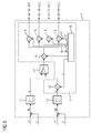
- the control device 11 is preferably corresponding FIG. 1 designed as a software programmable control device 11.
- the control device 11 is programmed in this case by means of a software module 12.
- the software module 12 may be supplied to the control device 11, for example by means of a data carrier 13, on which the software module 12 is stored in machine-readable form.
- a disk 13 comes in principle any disk in Question. Shown is (purely by way of example) in FIG. 1 a CD-ROM 13.
- the software module 12 includes machine code 14, which can be processed by the control device 11.
- the execution of the machine code 14 by the control device 11 causes the control device 11 controls the hydraulic cylinder unit 1, as will be explained in more detail below.
- the programming of the control device 11 with the software module 12 effects the corresponding design of the control device 11.
- the controller 11 are according to FIG. 1 First, a desired value s *, F * and an actual size s, F fed. It is possible that the supplied quantities s *, F *, s, F are a desired position s * to be assumed by the piston 3 and the actual position s assumed by the piston 3. Alternatively, it is possible that the supplied quantities s *, F *, s, F are a desired force F * to be exerted by the piston 3 and an actual force F exerted by the piston 3. According to FIG. 3 it is alternatively still possible that the control device 11 both value pairs s *, s, F *, F are fed and that is determined by means of a switching device 11 ', whether a position controller 15 or a force regulator 15' of the control device 11 is active.
- the regulators 15, 15 ' can in principle be any controllers. An embodiment of the controller 15, 15 'as a P controller is, however, usually sufficient and also preferred.
- control device 11 determines by means of the corresponding regulator 15, 15' on the basis of the difference ⁇ s, ⁇ F of the setpoint s *, F * and actual size s, F is a provisional manipulated variable u, u 'for the valve control device 7 and outputs the manipulated variable u, u'.
- the control device 11 thereby performs the corresponding control of the hydraulic cylinder unit 1 (more precisely: the piston 3).
- the regulators 15, 15 ' is according to FIG. 3 downstream of a linearization unit 17.
- the linearization unit 17 has multipliers 18 and a detection device 19.
- the determination means 19 determines in a manner to be explained linearization factors fa to fd and outputs the linearization factors fa to fd to the multipliers 18.
- the multipliers 18 continue to receive from the controller 15 the provisional manipulated variable u, u 'and multiply the provisional manipulated variable u, u' with the linearization factors fa to fd supplied to them.
- the linearization unit 17 determines in this way the final manipulated variables ua to ud, which are output to the valve control units 7a to 7d.
- valve control units 7a to 7d adjust according to the control variables transmitted to them, inter alia, to ud. This causes the piston 3 is displaced or adjusted at an adjustment speed v.
- the determination device 19 of the linearization unit 17 determines the linearization factors fa to fd dynamically as a function of at least the actual position s of the piston 3, the working pressures pA, pB prevailing on both sides of the piston 3 and the working pressures pP, pT prevailing on the pump and tank side of the valve control units 7a to 7d.
- the determination device 19 determines the linearization factors fa to fd such that a ratio of the adjustment speed v for position control to the difference ⁇ s of the setpoint position s * and actual position s and force control to the difference ⁇ F of the setpoint force F * and actual force F is independent of the actual position s and the working pressures pA, pB, pP, pT.
- the control device 11 is usually clocked with a power stroke T. With the frequency of the working clock T takes the control device 11 in each case a new setpoint s *, F * and a new actual size s, F opposite determines the control variables, inter alia, to ud and outputs the control variables, inter alia, to ud to the valve control units 7a to 7d.
- the determination device 19 is in each case supplied with a new value for the actual position s and the working pressures pA, pB prevailing on both sides of the piston 3. Furthermore, the determination device 19 is supplied with the sign of the control difference ⁇ s, ⁇ F. The cyclic feeding of these quantities s, pA, pB, ⁇ s, ⁇ F is in the FIG. 4 and 5 indicated that the detection means 19 is a latch 19 'upstream, which is clocked with the power stroke T.
- the pump pressure pP and the tank pressure pT are usually constant. It is therefore possible to supply these two pressures pP, pT to the determination device 19 once (that is to say in advance and therefore as a parameter). Alternatively, however, it is also possible to clock the pump-side working pressure pP and the tank-side working pressure pT of the determination device 19 and thus to supply it as a variable.
- the determination device 19 requires further data for the exact calculation of the linearization factors fa to fd.
- the further data generally include performance data pN, QNA, QNB of the valve control unit 7, the working surfaces AKA, AKB effective on both sides of the piston 3 as well as the minimum possible effective volumes VminA, VminB on both sides of the piston 3. These values may be fixedly assigned to the determination device 19, for example by the software module 12. Alternatively, the further data may be predetermined to the determination device 19 after the control device 11 has been programmed as a parameter (ie during the startup of the control device 11) be maintained unchanged during operation of the control device 11.
- the linearization factors fa to fd can be according to FIG. 3 as a product of a base linearization factor f and a respective additional linearization factor fa 'to fd'.
- the base linearization factor f is uniform for all linearization factors fa to fd.
- the additional linearization factors fa 'to fd' are individual for the respective linearization factor fa to fd.
- the base linearization factor f is dependent on the sign of the control difference ⁇ s, ⁇ F. In the case of a position control, the base linearization factor f is thus dependent on the direction of movement of the piston 3, that is, on the direction in which the piston 3 is to be displaced. In the following it is assumed that the control difference ⁇ s, ⁇ F is greater than zero.
- the Basislinearmaschines tone f thus corresponds to the (single) linearization factor, which in the DE 10 2007 051 857 B3 and the corresponding US script is determined.
- the determination device 19 takes into account the FIG. 4 and 5 preferably in addition a parameter P which is supplied to the detection device 19 from the outside, for example by an operator.
- the parameter P may be a binary value, may be an analog variable, may be a plurality of binary values, and may even be a plurality of analog variables.
- the determination device 19 sets according to FIG. 4 the additional linearization factors fa 'and fd' to non-zero values, the additional linearization factors fb 'and fc' to the value zero.
- the additional linearization factors fa 'and fd' can in particular have the same value, for example the value 1.
- the determination device 19 sets according to FIG. 4 the additional linearization factors fb ' and fc 'to values other than zero, the additional linearization factors fa' and fd 'to the value zero.
- the additional linearization factors fb 'and fc' may in particular have the same value, for example the value 1.
- the additional linearization factors fb 'and fc' in this case have the value zero.
- the additional linearization factors fa 'and fd' in this case have the value zero.
- E means the elasticity constant of the hydraulic fluid 10.
- the inventive arrangement of hydraulic cylinder unit 1 and control device 11 is in principle arbitrarily applicable. Preferably, however, it is according to FIG. 6 for the employment regulation of an in FIG. 6 schematically indicated rolling stand 20 used.
- the present invention has many advantages.
- an optimal operation of the control device 11 takes place at each operating point of the hydraulic cylinder unit 1.
- the control is completely linearized. Transformations (compare non-linear HGC) are not required.
- a simple integration of the present invention into existing control systems possible because already existing superimposed control structures (meshed controls and the like) need not be changed. This results in a simplified commissioning and maintainability of the control device 11 according to the present invention.
Description
Die vorliegende Erfindung geht aus von einer Regeleinrichtung zum Regeln einer Hydraulikzylindereinheit,
- wobei die Regeleinrichtung einen Regler aufweist, der eingangsseitig eine Sollgröße und eine Istgröße entgegen nimmt und anhand der Differenz von Sollgröße und Istgröße eine vorläufige Stellgröße für eine Ventilsteuereinheit der Hydraulikzylindereinheit ermittelt,
- wobei die Sollgröße eine von einem Kolben der Hydraulikzylindereinheit anzunehmende Sollstellung und die Istgröße eine vom Kolben angenommene Iststellung sind oder die Sollgröße eine vom Kolben auszuübende Sollkraft und die Istgröße eine vom Kolben ausgeübte Istkraft sind,
- wobei dem Regler eine Linearisierungseinheit nachgeordnet ist, welche anhand der vorläufigen Stellgröße und eines Linearisierungsfaktors eine endgültige Stellgröße ermittelt, die sie an eine Ventilsteuereinheit ausgibt, so dass der Kolben mit einer Verstellgeschwindigkeit verstellt wird,
- wobei die Linearisierungseinheit den Linearisierungsfaktor dynamisch als Funktion der Iststellung des Kolbens und beidseitig des Kolbens sowie pumpen- und tankseitig der Ventilsteuereinheit herrschender Arbeitsdrücke bestimmt,
- wobei die Linearisierungseinheit den Linearisierungsfaktor derart bestimmt, dass ein Verhältnis der Verstellgeschwindigkeit zur Differenz von Sollgröße und Istgröße unabhängig von der Iststellung des Kolbens und den Arbeitsdrücken ist.
- wherein the control device has a controller, the input side receives a desired size and an actual size and based on the difference between the target size and actual size a provisional control variable for a valve control unit of the hydraulic cylinder unit determined
- wherein the target size is a target position to be assumed by a piston of the hydraulic cylinder unit and the actual size is an actual position assumed by the piston, or the desired value is a desired force to be exerted by the piston and the actual value is an actual force exerted by the piston,
- wherein the controller is followed by a linearization unit, which determines a final control variable based on the provisional manipulated variable and a linearization factor, which outputs it to a valve control unit, so that the piston is adjusted at an adjusting speed,
- wherein the linearization unit determines the linearization factor dynamically as a function of the actual position of the piston and on both sides of the piston and on the pump and tank side of the valve control unit prevailing working pressures,
- wherein the linearization unit determines the linearization factor such that a ratio of the adjustment speed to the difference between the setpoint variable and actual size is independent of the actual position of the piston and the working pressures.
Zum Verbessern des Regelverhaltens ist im Stand der Technik bekannt, als Regelcharakteristik des Reglers eine so genannte Schmetterlingskurve vorzusehen. Die Schmetterlingskurve deckt jedoch nicht den gesamten Raum möglicher Betriebspunkte ab und arbeitet daher nicht in jedem Betriebszustand optimal.To improve the control behavior, it is known in the prior art to provide a so-called butterfly curve as the control characteristic of the regulator. However, the butterfly curve does not cover the entire space of possible operating points and therefore does not work optimally in every operating state.
Weiterhin ist es für Positionsregler für Hydraulikzylindereinheiten bekannt, für die Sollstellung und die Iststellung unabhängig voneinander je eine nichtlineare Transformation vorzunehmen und zusätzlich eine Teillinearisierung des Positionsreglers vorzunehmen. Diese Vorgehensweise ist sehr aufwändig.Furthermore, it is known for position controller for hydraulic cylinder units, each independently perform a non-linear transformation for the desired position and the actual position and also make a partial linearization of the position controller. This procedure is very complicated.
Aus der
Die Aufgabe der vorliegenden Erfindung besteht darin, Möglichkeiten zu schaffen, mittels derer eine Regeleinrichtung der eingangs genannten Art auf einfache Weise flexibler einsetzbar ist.The object of the present invention is to provide possibilities by means of which a control device of the type mentioned in a simple way is more flexible.
Die Aufgabe wird durch eine Regeleinrichtung mit den Merkmalen des Anspruchs 1 gelöst. Die Ansprüche 2 bis 6 betreffen vorteilhafte Ausgestaltungen der Regeleinrichtung.The object is achieved by a control device having the features of
Erfindungsgemäß wird vorgeschlagen, eine Regeleinrichtung zum Regeln einer Hydraulikzylindereinheit zu schaffen,
- wobei die Regeleinrichtung einen Regler aufweist, der eingangsseitig eine Sollgröße und eine Istgröße entgegen nimmt und anhand der Differenz von Sollgröße und Istgröße eine vorläufige Stellgröße für Ventilsteuereinheiten der Hydraulikzylindereinheit ermittelt,
- wobei die Sollgröße eine von einem Kolben der Hydraulikzylindereinheit anzunehmende Sollstellung und die Istgröße eine vom Kolben angenommene Iststellung sind oder die Sollgröße eine vom Kolben auszuübende Sollkraft und die Istgröße eine vom Kolben ausgeübte Istkraft sind,
- wobei dem Regler eine Linearisierungseinheit nachgeordnet ist, welche anhand der vorläufigen Stellgröße und Linearisierungsfaktoren endgültige Stellgrößen ermittelt, die sie an Ventilsteuereinheiten ausgibt, so dass der Kolben mit einer Verstellgeschwindigkeit verstellt wird,
- wobei die Linearisierungseinheit die Linearisierungsfaktoren dynamisch als Funktion zumindest der Iststellung des Kolbens und beidseitig des Kolbens sowie pumpen- und tankseitig der Ventilsteuereinheiten herrschender Arbeitsdrücke bestimmt,
- wobei die Linearisierungseinheit die Linearisierungsfaktoren derart bestimmt, dass ein Verhältnis der Verstellgeschwindigkeit zur Differenz von Sollgröße und Istgröße unabhängig von der Iststellung des Kolbens und den Arbeitsdrücken ist.
- wherein the control device has a controller, the input side receives a desired size and an actual size and based on the difference between the target size and actual size determines a provisional control variable for valve control units of the hydraulic cylinder unit,
- wherein the target size to be assumed by a piston of the hydraulic cylinder unit reference position and the actual size is an assumed by the piston actual position or the target size a desired force to be exerted by the piston and the actual quantity are an actual force exerted by the piston,
- wherein the controller is followed by a linearization unit, which determines the final control variables based on the provisional manipulated variable and linearization factors, which it outputs to valve control units, so that the piston is adjusted at an adjustment speed,
- wherein the linearization unit dynamically determines the linearization factors as a function of at least the actual position of the piston and on both sides of the piston as well as prevailing working pressures on the pump and tank side of the valve control units,
- wherein the linearization unit determines the linearization factors such that a ratio of the adjustment speed to the difference between the setpoint variable and actual size is independent of the actual position of the piston and the working pressures.
Erfindungsgemäß sind also mehrere Ventilsteuereinheiten vorhanden, für die individuell jeweils eine endgültige Stellgröße ermittelt wird.According to the invention, therefore, a plurality of valve control units are present, for each of which a final manipulated variable is determined individually.
Vorzugsweise wird der Linearisierungseinheit zusätzlich ein Parameter zugeführt, den die Linearisierungseinheit bei der Bestimmung der Linearisierungsfaktoren berücksichtigt. Dadurch kann mindestens eine weitere Randbedingung eingehalten werden.Preferably, the linearization unit is additionally supplied with a parameter which the linearization unit takes into account when determining the linearization factors. As a result, at least one further boundary condition can be met.
Im einfachsten Fall bestimmt die Linearisierungseinheit in dem Fall, dass der Parameter einen ersten Wert aufweist, die Linearisierungsfaktoren derart, dass zwei der Linearisierungsfaktoren den Wert Null aufweisen und zwei andere der Linearisierungsfaktoren von Null verschiedene Werte aufweisen. Die beiden anderen Linearisierungsfaktoren können insbesondere untereinander den gleichen Wert aufweisen. In diesem Fall ergibt sich das gleiche Verhalten wie bei einer konventionellen einzelnen Ventilsteuereinheit, also wie bei der
Alternativ oder zusätzlich ist es möglich, dass die Linearisierungseinheit in dem Fall, dass der Parameter einen zweiten Wert aufweist, die Linearisierungsfaktoren derart bestimmt, dass die Summe der beidseitig des Kolbens herrschenden Arbeitsdrücke sich der Summe der pumpen- und tankseitig der Ventilsteuereinheiten herrschenden Arbeitsdrücke annähert. In diesem Fall ergibt sich eine besonders niedrige Druckdifferenz an den Ventilsteuereinheiten.Alternatively or additionally, it is possible for the linearization unit, in the case where the parameter has a second value, to determine the linearization factors in such a way that the sum of the working pressures prevailing on both sides of the piston approaches the sum of the working pressures prevailing on the pump and tank side of the valve control units. In this case, a particularly low pressure difference results on the valve control units.
Es ist möglich, dass die Ventilsteuereinheiten als Proportionalventile ausgebildet sind. Vorzugsweise sind die Ventilsteuereinheiten jedoch als binär geschaltete Schaltventile ausgebildet.It is possible that the valve control units are designed as proportional valves. Preferably, however, the valve control units are designed as binary switching valves.
Die Regeleinrichtung kann als Hardwarestruktur ausgebildet sein. Vorzugsweise ist sie jedoch als softwareprogrammierbare Regeleinrichtung ausgebildet und mit einem Softwaremodul programmiert, so dass sie auf Grund der Programmierung mit dem Softwaremodul erfindungsgemäß ausgebildet ist.The control device can be designed as a hardware structure. Preferably, however, it is designed as a software programmable control device and programmed with a software module, so that it is formed according to the invention due to the programming with the software module.
Das Softwaremodul umfasst Maschinencode, dessen Abarbeitung durch eine an eine Hydraulikzylindereinheit angebundene softwareprogrammierbare Regeleinrichtung, bewirkt, dass die Regeleinrichtung wie obenstehend beschrieben ausgebildet wird. Das Softwaremodul kann in maschinenlesbarer Form auf einem Datenträger gespeichert sein.The software module comprises machine code whose execution by a software programmable control device connected to a hydraulic cylinder unit causes the control device to be designed as described above. The software module may be stored in machine-readable form on a data carrier.
Prinzipiell ist die erfindungsgemäße Regeleinrichtung universell verwendbar. Vorzugsweise jedoch wird sie zur Anstellungsregelung eines Walzgerüsts verwendet.In principle, the control device according to the invention is universally applicable. Preferably, however, it is used for employment control of a roll stand.
Die oben beschriebenen Eigenschaften, Merkmale und Vorteile dieser Erfindung sowie die Art und Weise, wie diese erreicht werden, werden klarer und deutlicher verständlich im Zusammenhang mit der folgenden Beschreibung der Ausführungsbeispiele, die in Verbindung mit den Zeichnungen näher erläutert werden. Hierbei zeigen in schematischer Darstellung:
- FIG 1
- ein Blockschaltbild einer Regeleinrichtung und einer Hydraulikzylindereinheit,
- FIG 2
- den Aufbau einer Ventilsteuereinrichtung,
- FIG 3
- den Aufbau der Regeleinrichtung,
- FIG 4 und 5
- je eine Ermittlungseinrichtung einer Linearisierungseinheit und
- FIG 6
- eine Anstellungseinrichtung für eine Walze eines Walzgerüsts.
- FIG. 1
- a block diagram of a control device and a hydraulic cylinder unit,
- FIG. 2
- the construction of a valve control device,
- FIG. 3
- the structure of the control device,
- 4 and 5
- one determination device each of a linearization unit and
- FIG. 6
- a setting device for a roll of a roll stand.
Gemäß
Der Kolben 3 weist eine erste Arbeitsfläche 4A und eine zweite Arbeitsfläche 4B auf. Jede Arbeitsfläche 4A, 4B ist einem entsprechenden Arbeitsvolumen 5A, 5B zugewandt.The
Die Arbeitsvolumina 5A, 5B sind über Hydraulikpfade 6A, 6B und eine Ventilsteuereinrichtung 7 mit einer Hydraulikpumpe 8 und einem Hydraulikreservoir 9 hydraulisch verbunden. Die Hydraulikpfade 6A, 6B erstrecken sich hierbei von dem jeweiligen Arbeitsvolumen 5A, 5B bis zur Ventilsteuereinrichtung 7.The working
Wenn der Kolben 3 sich in seiner Minimalstellung smin befindet, befindet sich im Hydraulikpfad 6A ein bestimmtes Volumen einer Hydraulikflüssigkeit 10. Dieses Volumen ist die minimale Menge an Hydraulikflüssigkeit 10, die sich zwischen der Ventilsteuereinrichtung 7 und der Arbeitsfläche 4A des Kolbens 3 befindet. Diese Menge an Hydraulikflüssigkeit 10 ist das minimal mögliche wirksame Volumen für das Arbeitsvolumen 5A. Es wird nachfolgend mit dem Bezugszeichen VminA bezeichnet.When the
In analoger Weise befindet sich im Hydraulikpfad 6B eine bestimmte Menge an Hydraulikflüssigkeit 10, wenn der Kolben 3 sich in seiner Maximalstellung smax befindet. Diese Menge an Hydraulikflüssigkeit 10 stellt ein minimal mögliches wirksames Volumen für das Arbeitsvolumen 5B dar. Dieses Minimalvolumen wird nachfolgend mit dem Bezugszeichen VminB bezeichnet.In an analogous manner, there is a certain amount of
Wenn der Kolben 3 sich bei einer beliebigen Iststellung s befindet, weist das Arbeitsvolumen 5A einen Volumenwert VA auf, der sich zu ![]()
![]()
![]()
![]()
In analoger Weise können anhand des minimal möglichen wirksamen Volumens VminB, des Flächenwerts AKB der dem Arbeitsvolumen 5B zugewandten Arbeitsfläche 4B, der Iststellung s und der Maximalstellung smax gemäß den Beziehungen ![]()
![]()
![]()
![]()
Im Arbeitsvolumen 5A herrscht ein erster Arbeitsdruck pA, im zweiten Arbeitsvolumen 5B ein zweiter Arbeitsdruck pB. Über die Hydraulikpumpe 8 wird die Hydraulikflüssigkeit 10 mit einem Pumpendruck pP beaufschlagt. Im Hydraulikreservoir 9 herrscht ein Tankdruck pT. Der Pumpendruck pP und der Tankdruck pT entsprechen einem pumpenseitig und einem tankseitig der Ventilsteuereinheit 7 herrschenden Arbeitsdruck.In the working
Die Ventilsteuereinrichtung 7 weist gemäß
Es ist möglich, dass die Ventilsteuereinheiten 7a bis 7d Proportionalventile sind. Vorzugsweise handelt es sich jedoch um binär geschaltete Schaltventile, die also nur zwischen den Zuständen vollständig geöffnet und vollständig geschlossen hin und her geschaltet werden können, aber keine definierten Zwischenzustände annehmen können. Die Ansteuerung der Ventilsteuereinheiten 7a bis 7d erfolgt in diesem Fall durch eine pulsweitenmodulierte und/oder pulscodemodulierte Ansteuerung.It is possible that the
Die Ventilsteuereinrichtung 7 und mit ihr die gesamte Hydraulikzylindereinheit 1 wird mittels einer Regeleinrichtung 11 geregelt. Die Regeleinrichtung 11 ist vorzugsweise entsprechend
Das Softwaremodul 12 umfasst Maschinencode 14, der von der Regeleinrichtung 11 abarbeitbar ist. Das Abarbeiten des Maschinencodes 14 durch die Regeleinrichtung 11 bewirkt, dass die Regeleinrichtung 11 die Hydraulikzylindereinheit 1 so regelt, wie dies nachfolgend näher erläutert wird. Die Programmierung der Regeleinrichtung 11 mit dem Softwaremodul 12 bewirkt die entsprechende Ausbildung der Regeleinrichtung 11.The
Der Regeleinrichtung 11 werden gemäß
Unabhängig davon, ob die Regeleinrichtung 11 als Positionsregler 15 oder als Kraftregler 15' oder als zwischen Positions- und Kraftregelung umschaltbarer Regler ausgebildet ist, ermittelt die Regeleinrichtung 11 mittels des entsprechenden Reglers 15, 15' anhand der Differenz δs, δF von Sollgröße s*, F* und Istgröße s, F eine vorläufige Stellgröße u, u' für die Ventilsteuereinrichtung 7 und gibt die Stellgröße u, u' aus. Die Regeleinrichtung 11 führt dadurch die entsprechende Regelung der Hydraulikzylindereinheit 1 (genauer: des Kolbens 3) durch.Regardless of whether the
Den Reglern 15, 15' ist gemäß
Die Ventilsteuereinheiten 7a bis 7d stellen sich entsprechend den an sie übermittelten Stellgrößen ua bis ud ein. Dadurch wird bewirkt, dass der Kolben 3 mit einer Verstellgeschwindigkeit v verschoben bzw. verstellt wird.The
Die Ermittlungseinrichtung 19 der Linearisierungseinheit 17 bestimmt die Linearisierungsfaktoren fa bis fd dynamisch als Funktion zumindest der Iststellung s des Kolbens 3, der beidseitig des Kolbens 3 herrschenden Arbeitsdrücke pA, pB sowie der pumpen- und tankseitig der Ventilsteuereinheiten 7a bis 7d herrschenden Arbeitsdrücke pP, pT. Die Ermittlungseinrichtung 19 bestimmt die Linearisierungsfaktoren fa bis fd derart, dass ein Verhältnis der Verstellgeschwindigkeit v bei Positionsregelung zur Differenz δs von Sollstellung s* und Iststellung s und bei Kraftregelung zur Differenz δF von Sollkraft F* und Istkraft F unabhängig von der Iststellung s und den Arbeitsdrücken pA, pB, pP, pT ist.The
Die Wirkungsweise der Ermittlungseinrichtung 19 wird nachfolgend in Verbindung mit den
Die Regeleinrichtung 11 ist üblicherweise mit einem Arbeitstakt T getaktet. Mit der Frequenz des Arbeitstaktes T nimmt die Regeleinrichtung 11 jeweils eine neue Sollgröße s*, F* und eine neue Istgröße s, F entgegen, ermittelt die Stellgrößen ua bis ud und gibt die Stellgrößen ua bis ud an die Ventilsteuereinheiten 7a bis 7d aus.The
Ebenfalls mit dem Arbeitstakt T wird der Ermittlungseinrichtung 19 jeweils ein neuer Wert für die Iststellung s und die beidseitig des Kolbens 3 herrschenden Arbeitsdrücke pA, pB zugeführt. Weiterhin wird der Ermittlungseinrichtung 19 das Vorzeichen der Regeldifferenz δs, δF zugeführt. Das taktweise Zuführen dieser Größen s, pA, pB, δs, δF ist in den
Der Pumpendruck pP und der Tankdruck pT sind in der Regel konstant. Es ist daher möglich, diese beiden Drücke pP, pT der Ermittlungseinrichtung 19 einmalig (d. h. vorab und damit als Parameter) zuzuführen. Alternativ ist jedoch ebenfalls möglich, den pumpenseitigen Arbeitsdruck pP und den tankseitigen Arbeitsdruck pT der Ermittlungseinrichtung 19 getaktet und damit als Variable zuzuführen.The pump pressure pP and the tank pressure pT are usually constant. It is therefore possible to supply these two pressures pP, pT to the
In der Regel benötigt die Ermittlungseinrichtung 19 zur exakten Berechnung der Linearisierungsfaktoren fa bis fd weitere Daten. Die weiteren Daten umfassen in der Regel Leistungsdaten pN, QNA, QNB der Ventilsteuereinheit 7, die beidseitig des Kolbens 3 wirksamen Arbeitsflächen AKA, AKB sowie die beidseits des Kolbens 3 minimal möglichen wirksamen Volumina VminA, VminB. Diese Werte können der Ermittlungseinrichtung 19 fest vorgegeben sein, beispielsweise durch das Softwaremodul 12. Alternativ können die weiteren Daten - zumindest teilweise - der Ermittlungseinrichtung 19 nach der Programmierung der Regeleinrichtung 11 als Parameter (d. h. im Rahmen der Inbetriebsetzung der Regeleinrichtung 11) vorgegeben werden, die während des Betriebs der Regeleinrichtung 11 unverändert beibehalten werden.As a rule, the
Die Linearisierungsfaktoren fa bis fd lassen sich gemäß
Der Basislinearisierungsfaktor f ist abhängig vom Vorzeichen der Regeldifferenz δs, δF. Im Falle einer Positionsregelung ist der Basislinearisierungsfaktor f damit abhängig von der Bewegungsrichtung des Kolbens 3, das heißt von der Richtung, in die der Kolben 3 verschoben werden soll. Nachfolgend wird angenommen, dass die Regeldifferenz δs, δF größer als Null ist. In diesem Fall bestimmt die Ermittlungseinrichtung 19 den Basislinearisierungsfaktor f vorzugsweise zu 
Die in obiger Formel verwendeten Größen sind - mit Ausnahme der Leistungsdaten pN, QNA, QNB der Ventilsteuereinheit 7 bereits definiert. Die Leistungsdaten pN, QNA und QNB der Ventilsteuereinheit 7 haben folgende Bedeutung:
- pN ist ein (prinzipiell beliebiger) Nominaldruck. Er entspricht einem Referenzdruck, auf den die Größen QNA1, QNA2, QNB1 und QNB2 normiert sind.
- QNA1 ist ein Nennvolumenstrom, der in
das Arbeitsvolumen 5A strömt, wenn eine Differenz zwischen dem Pumpendruck pP unddem im Arbeitsvolumen 5A herrschenden Arbeitsdruck pA gleich dem Nominaldruck pN ist. - QNA2 ist ein Nennvolumenstrom, der aus
dem Arbeitsvolumen 5A strömt, wenn eine Differenz zwischen dem Arbeitsdruck pA und dem Tankdruck pT gleich dem Nominaldruck pN ist. - QNB1 und QNB2 sind - bezogen auf
das Arbeitsvolumen 5B - in analoger Weise definiert. - K ist ein frei wählbarer Skalierungsfaktor.
- pN is a (in principle any) nominal pressure. It corresponds to a reference pressure to which the quantities QNA1, QNA2, QNB1 and QNB2 are normalized.
- QNA1 is a rated volume flow that flows into the working
volume 5A when a difference between the pump pressure pP and the working pressure pA prevailing in the workingvolume 5A is equal to the nominal pressure pN. - QNA2 is a rated volume flow that flows out of the working
volume 5A when a difference between the working pressure pA and the tank pressure pT is equal to the nominal pressure pN. - QNB1 and QNB2 are defined analogously with respect to the working
volume 5B. - K is a freely selectable scaling factor.
Wie bereits erwähnt, ist der Basislinearisierungsfaktor f vom Vorzeichen der Regeldifferenz δs, δF abhängig. In dem Fall, dass die Regeldifferenz δs, δF negativ ist, ergibt sich der Basislinearisierungsfaktor f vorzugsweise zu 
Der Basislinearisierungsfaktor f entspricht somit dem (einzigen) Linearisierungsfaktor, der in der
Bei der Bestimmung der Zusatzlinearisierungsfaktoren fa' bis fd' berücksichtigt die Ermittlungseinrichtung 19 gemäß den
Wenn die Regeldifferenz δs, δF positiv ist und der Parameter P einen ersten Wert P1 aufweist, setzt die Ermittlungseinrichtung 19 gemäß
Wenn die Regeldifferenz δs, δF negativ ist und der Parameter P einen ersten Wert P1 aufweist, setzt die Ermittlungseinrichtung 19 gemäß
Wenn der Parameter P einen zweiten Wert P2 aufweist, bestimmt die Ermittlungseinrichtung 19 die Zusatzlinearisierungsfaktoren fa' bis fd' gemäß ![]()
![]()

![]()
![]()
Die Zusatzlinearisierungsfaktoren fb' und fc' weisen in diesem Fall den Wert Null auf.The additional linearization factors fb 'and fc' in this case have the value zero.
Wenn die Regeldifferenz δs, δF hingegen negativ ist, bestimmt die Ermittlungseinrichtung 19 in diesem Fall die Zusatzlinearisierungsfaktoren fb' und fc' zu ![]()

![]()
Die Zusatzlinearisierungsfaktoren fa' und fd' weisen in diesem Fall den Wert Null auf.The additional linearization factors fa 'and fd' in this case have the value zero.
Obenstehend wurde eine Vorgehensweise erläutert, bei welcher die Linearisierungsfaktoren fa bis fd als Produkt des Basislinearisierungsfaktors f und eines jeweiligen Zusatzlinearisierungsfaktors fa' bis fd' ermittelt werden. Es ist selbstverständlich auch eine direkte Ermittlung der Linearisierungsfaktoren fa bis fd - also ohne Umweg über die Produktbildung - möglich.In the above, a procedure has been explained in which the linearization factors fa to fd are determined as a product of the base linearization factor f and a respective additional linearization factor fa 'to fd'. Of course, it is also possible to directly determine the linearization factors fa to fd-that is, without going through product formation.
Obenstehend wurden weiterhin die Linearisierungsfaktoren fa bis fd ermittelt, welche erforderlich sind, um eine Linearisierung im positionsgeregelten Betrieb der Hydraulikzylindereinheit 1 zu bewirken. Falls eine Kraftregelung erfolgt, ist gemäß der Darstellung in ![]()
![]()
E bedeutet hierbei die Elastizitätskonstante der Hydraulikflüssigkeit 10.E means the elasticity constant of the
Die erfindungsgemäße Anordnung aus Hydraulikzylindereinheit 1 und Regeleinrichtung 11 ist prinzipiell beliebig einsetzbar. Vorzugsweise wird sie jedoch gemäß
Die vorliegende Erfindung weist viele Vorteile auf. Insbesondere erfolgt in jedem Betriebspunkt der Hydraulikzylindereinheit 1 ein optimaler Betrieb der Regeleinrichtung 11. Die Regelung ist vollständig linearisiert. Transformationen (vergleiche nicht lineares HGC) sind nicht erforderlich. Weiterhin ist - ebenfalls im Gegensatz zum nicht linearen HGC - auf einfache Weise eine Einbindung der vorliegenden Erfindung in bereits vorhandene Regelsysteme möglich, da bereits vorhandene überlagerte Regelstrukturen (vermaschte Regelungen und dergleichen) nicht verändert werden müssen. Es ergibt sich damit eine vereinfachte Inbetriebsetzung und Wartbarkeit der Regeleinrichtung 11 gemäß der vorliegenden Erfindung.The present invention has many advantages. In particular, at each operating point of the
Claims (9)
- Control device for controlling a hydraulic cylinder unit (1),- wherein the control device has a controller (15, 15') designed, on the input side, to accept a setpoint variable (s*, F*) and an actual variable (s, F) and on the basis of the difference (δs, δF) between setpoint variable (s*, F*) and actual variable (s, F), to determine a preliminary manipulated variable (u, u') for valve control units (7) of the hydraulic cylinder unit (1),- wherein the setpoint variable (s*, F*) is a setpoint position (s*) to be taken up by a piston (3) of the hydraulic cylinder unit (1) and the actual variable (s, F) is an actual position (s) taken up by the piston (3) or the setpoint variable (s*, F*) is a setpoint force (F*) to be exerted by the piston (3) and the actual variable (s, F) is an actual force (F) to be exerted by the piston (3),- wherein a linearisation unit (17) is arranged downstream of the controller (15, 15') designed, on the basis of the preliminary manipulated variable (u, u') and linearisation factors (fa to fd), to determine definitive manipulated variables (ua to ud) and to output them to valve control units (7a to 7d) so that the piston (3) is adjusted with an adjustment speed (v),- wherein the linearisation unit (17) is designed to determine the linearisation factors (fa to fd) dynamically as a function at least of the actual position (s) of the piston (3) and to determine working pressures (pA, pB, pP, pT) obtaining on both sides of the piston (3) as well as on the pump and tank side of the valve control units (7a to 7d),- wherein the linearisation unit (17) is designed to determine the linearisation factors (fa to fd) such that a ratio of the adjustment speed (v) to the difference (δs, δF) between setpoint variable (s*, F*) and actual variable (s, F) is independent of the actual position (s) of the cylinder (3) and the working pressures (pA, pB, pP, pT).
- Control device according to claim 1,
characterised in that the linearisation unit (17) is additionally supplied with a parameter (P) and the linearisation unit (17) is designed to take account of the parameter (P) in the determination of the linearisation factors (fa to fd). - Control device according to claim 2,
characterised in that the linearisation unit (17) is designed, in the event of the parameter (P) having a first value (P1), to determine the linearisation factors (fa to fd) such that two of the linearisation factors (fa to fd) have the value zero and two other linearisation factors (f) have a value differing from zero. - Control device according to claim 2 or 3,
characterised in that the linearisation unit (17) is designed, in the event of the parameter (P) having a second value (P2), to determine the linearisation factors (fa to fd) such that the sum of the working pressures (pA, pB) obtaining on both sides of the piston (3) approximates to the sum of the working pressures (pP, pT) of obtaining on the pump side and tank side of the valve control units (7a to 7d). - Control device according to one of the above claims,
characterised in that the valve control units (7a to 7d) are embodied as binary-switched switching valves. - Control device according to one of the above claims,
characterised in that it is embodied as a software-programmable control device and is programmed with a software module (12) so that, as a result of the programming with the software module, it is embodied according to one of the above claims. - Software module having machine code (14), characterised in that on the basis of the programming with the software module a software-programmable control device (11) linked to a hydraulic cylinder unit (1) is embodied as control device (11) according to claim 6.
- Data medium on which a software module (12) according to claim 7 is stored in machine-readable form.
- Use of a hydraulic cylinder unit controlled by means of a control device (11) according to one of claims 1 to 6 for adjustment control of a roll stand (20).
Priority Applications (1)
| Application Number | Priority Date | Filing Date | Title |
|---|---|---|---|
| EP13722706.2A EP2836879B1 (en) | 2012-05-16 | 2013-04-24 | Control device for a hydraulic cylinder unit with single valve control |
Applications Claiming Priority (3)
| Application Number | Priority Date | Filing Date | Title |
|---|---|---|---|
| EP12168164.7A EP2664968A1 (en) | 2012-05-16 | 2012-05-16 | Control device for a hydraulic cylinder unit with single valve control |
| PCT/EP2013/058423 WO2013171041A1 (en) | 2012-05-16 | 2013-04-24 | Control device for a hydraulic cylinder unit with an individual valve controller |
| EP13722706.2A EP2836879B1 (en) | 2012-05-16 | 2013-04-24 | Control device for a hydraulic cylinder unit with single valve control |
Publications (2)
| Publication Number | Publication Date |
|---|---|
| EP2836879A1 EP2836879A1 (en) | 2015-02-18 |
| EP2836879B1 true EP2836879B1 (en) | 2016-11-23 |
Family
ID=48444339
Family Applications (2)
| Application Number | Title | Priority Date | Filing Date |
|---|---|---|---|
| EP12168164.7A Withdrawn EP2664968A1 (en) | 2012-05-16 | 2012-05-16 | Control device for a hydraulic cylinder unit with single valve control |
| EP13722706.2A Not-in-force EP2836879B1 (en) | 2012-05-16 | 2013-04-24 | Control device for a hydraulic cylinder unit with single valve control |
Family Applications Before (1)
| Application Number | Title | Priority Date | Filing Date |
|---|---|---|---|
| EP12168164.7A Withdrawn EP2664968A1 (en) | 2012-05-16 | 2012-05-16 | Control device for a hydraulic cylinder unit with single valve control |
Country Status (5)
| Country | Link |
|---|---|
| US (1) | US9945395B2 (en) |
| EP (2) | EP2664968A1 (en) |
| CN (1) | CN104412180B (en) |
| BR (1) | BR112014028402A2 (en) |
| WO (1) | WO2013171041A1 (en) |
Families Citing this family (1)
| Publication number | Priority date | Publication date | Assignee | Title |
|---|---|---|---|---|
| DE102019209091A1 (en) * | 2019-06-24 | 2020-12-24 | Festo Se & Co. Kg | Method for operating a fluid system, fluid system and computer program product |
Family Cites Families (12)
| Publication number | Priority date | Publication date | Assignee | Title |
|---|---|---|---|---|
| US3110152A (en) * | 1961-05-01 | 1963-11-12 | Int Harvester Co | Starting and operating control system for free piston engine hydraulic pump as a power plant of a hydrostatic driven vehicle |
| US4653986A (en) * | 1983-07-28 | 1987-03-31 | Tidewater Compression Service, Inc. | Hydraulically powered compressor and hydraulic control and power system therefor |
| DE3445516C1 (en) * | 1984-12-13 | 1989-05-18 | Mannesmann Rexroth GmbH, 8770 Lohr | Control device for a control pump |
| US7114432B1 (en) * | 2005-02-09 | 2006-10-03 | Sauer-Danfoss Inc. | Torque limiting device for hydraulic piston pump |
| DE102005042168A1 (en) * | 2005-06-08 | 2006-12-14 | Sms Demag Ag | Device for acting on the guide surfaces of guided in the stator windows of rolling stands bearing chocks |
| AT502348B1 (en) * | 2005-08-17 | 2008-09-15 | Voest Alpine Ind Anlagen | CONTROL METHOD AND REGULATOR FOR A MECHANICAL-HYDRAULIC SYSTEM WITH A MECHANICAL FREEDOM DEGREE PER HYDRAULIC ACTUATOR |
| JP4425253B2 (en) * | 2006-08-30 | 2010-03-03 | ダイキン工業株式会社 | Hydraulic unit and motor speed control method in hydraulic unit |
| DE102007003243A1 (en) * | 2007-01-23 | 2008-07-31 | Siemens Ag | Control arrangement for a roll stand and herewith corresponding objects |
| DE102007051857B3 (en) | 2007-10-30 | 2009-04-23 | Siemens Ag | Control device for position control of a hydraulic cylinder unit with linearization unit |
| DE102008003798A1 (en) * | 2008-01-10 | 2009-07-16 | Robert Bosch Gmbh | Method for controlling a solenoid valve |
| JP2008232445A (en) * | 2008-06-13 | 2008-10-02 | Daikin Ind Ltd | Hydraulic unit, and speed control method of motor of hydraulic unit |
| US8591200B2 (en) * | 2009-11-23 | 2013-11-26 | National Oil Well Varco, L.P. | Hydraulically controlled reciprocating pump system |
-
2012
- 2012-05-16 EP EP12168164.7A patent/EP2664968A1/en not_active Withdrawn
-
2013
- 2013-04-24 EP EP13722706.2A patent/EP2836879B1/en not_active Not-in-force
- 2013-04-24 BR BR112014028402A patent/BR112014028402A2/en not_active IP Right Cessation
- 2013-04-24 WO PCT/EP2013/058423 patent/WO2013171041A1/en active Application Filing
- 2013-04-24 CN CN201380025612.XA patent/CN104412180B/en not_active Expired - Fee Related
- 2013-04-24 US US14/401,684 patent/US9945395B2/en not_active Expired - Fee Related
Non-Patent Citations (1)
| Title |
|---|
| None * |
Also Published As
| Publication number | Publication date |
|---|---|
| EP2836879A1 (en) | 2015-02-18 |
| US20150142183A1 (en) | 2015-05-21 |
| EP2664968A1 (en) | 2013-11-20 |
| US9945395B2 (en) | 2018-04-17 |
| CN104412180A (en) | 2015-03-11 |
| BR112014028402A2 (en) | 2018-04-24 |
| WO2013171041A1 (en) | 2013-11-21 |
| CN104412180B (en) | 2017-01-18 |
Similar Documents
| Publication | Publication Date | Title |
|---|---|---|
| EP2206031B1 (en) | Control device for the position control of a hydraulic cylinder unit, comprising a linearization unit | |
| DE19839062C2 (en) | Hydraulic machine control | |
| DE102017213650A1 (en) | Method for controlling a hydraulic system, control unit for a hydraulic system and hydraulic system | |
| EP2664804A2 (en) | Pressure flow regulator, adjustment unit for an adjustable hydraulic displacement machine with a pressure flow regulator and method for controlling such an adjustment unit | |
| WO2018210448A2 (en) | Method for operating a powder press having an attitude control and powder press for carrying out the method | |
| EP2125258B1 (en) | Regulation device for a rolling stand and items corresponding thereto | |
| DE102016214708A1 (en) | Continuous valve unit, hydraulic axis and method for operating a hydraulic axis | |
| DE102006028094A1 (en) | Device for controlling an injection molding machine | |
| EP2836879B1 (en) | Control device for a hydraulic cylinder unit with single valve control | |
| EP0515639A1 (en) | Hydraulic system. | |
| EP3816455A1 (en) | Hydraulic control arrangement for supplying compressed media of at least two hydraulic consumers | |
| EP3953771A1 (en) | Hydrostatic working tool and method for controlling same | |
| EP2853752B1 (en) | Control system | |
| EP3134774B1 (en) | Control device for a hydraulic cylinder unit with optimised linearisation | |
| DE102006041223B4 (en) | Method for operating a hydraulic drive system, in particular for open-die forging a workpiece | |
| DE10134747B4 (en) | Method and device for load-dependent control of the fluid supply of a fluid circuit | |
| EP3230813B1 (en) | Method for identifying a characteristic curve | |
| WO2020156932A1 (en) | Controlling hydraulic actuating cylinders in roll stands | |
| DE102021108081B4 (en) | Device for controlling a hydraulic pump or a hydraulic motor | |
| EP3895819B1 (en) | Operation of a cooling device with minimum working pressure | |
| WO2010136271A2 (en) | Control method of a digital hydraulic controller | |
| DE102022208574A1 (en) | Method for operating a hydraulic drive of a machine and hydraulic drive | |
| EP2984527B1 (en) | Hydraulic assembly with decoupled operation of two valve devices | |
| DE102022205361A1 (en) | Cable winch with pressure-dependent adjustment of at least one hydraulic motor | |
| EP2449435B1 (en) | Control device for a hydraulic cylinder unit |
Legal Events
| Date | Code | Title | Description |
|---|---|---|---|
| PUAI | Public reference made under article 153(3) epc to a published international application that has entered the european phase |
Free format text: ORIGINAL CODE: 0009012 |
|
| 17P | Request for examination filed |
Effective date: 20141110 |
|
| AK | Designated contracting states |
Kind code of ref document: A1 Designated state(s): AL AT BE BG CH CY CZ DE DK EE ES FI FR GB GR HR HU IE IS IT LI LT LU LV MC MK MT NL NO PL PT RO RS SE SI SK SM TR |
|
| AX | Request for extension of the european patent |
Extension state: BA ME |
|
| RAP1 | Party data changed (applicant data changed or rights of an application transferred) |
Owner name: PRIMETALS TECHNOLOGIES GERMANY GMBH |
|
| DAX | Request for extension of the european patent (deleted) | ||
| GRAP | Despatch of communication of intention to grant a patent |
Free format text: ORIGINAL CODE: EPIDOSNIGR1 |
|
| INTG | Intention to grant announced |
Effective date: 20160802 |
|
| GRAS | Grant fee paid |
Free format text: ORIGINAL CODE: EPIDOSNIGR3 |
|
| GRAA | (expected) grant |
Free format text: ORIGINAL CODE: 0009210 |
|
| AK | Designated contracting states |
Kind code of ref document: B1 Designated state(s): AL AT BE BG CH CY CZ DE DK EE ES FI FR GB GR HR HU IE IS IT LI LT LU LV MC MK MT NL NO PL PT RO RS SE SI SK SM TR |
|
| REG | Reference to a national code |
Ref country code: GB Ref legal event code: FG4D Free format text: NOT ENGLISH |
|
| REG | Reference to a national code |
Ref country code: CH Ref legal event code: EP |
|
| REG | Reference to a national code |
Ref country code: IE Ref legal event code: FG4D Free format text: LANGUAGE OF EP DOCUMENT: GERMAN |
|
| REG | Reference to a national code |
Ref country code: AT Ref legal event code: REF Ref document number: 848458 Country of ref document: AT Kind code of ref document: T Effective date: 20161215 |
|
| REG | Reference to a national code |
Ref country code: DE Ref legal event code: R096 Ref document number: 502013005484 Country of ref document: DE |
|
| PG25 | Lapsed in a contracting state [announced via postgrant information from national office to epo] |
Ref country code: LV Free format text: LAPSE BECAUSE OF FAILURE TO SUBMIT A TRANSLATION OF THE DESCRIPTION OR TO PAY THE FEE WITHIN THE PRESCRIBED TIME-LIMIT Effective date: 20161123 |
|
| REG | Reference to a national code |
Ref country code: SE Ref legal event code: TRGR |
|
| REG | Reference to a national code |
Ref country code: LT Ref legal event code: MG4D |
|
| REG | Reference to a national code |
Ref country code: NL Ref legal event code: MP Effective date: 20161123 |
|
| REG | Reference to a national code |
Ref country code: FR Ref legal event code: PLFP Year of fee payment: 5 |
|
| PG25 | Lapsed in a contracting state [announced via postgrant information from national office to epo] |
Ref country code: GR Free format text: LAPSE BECAUSE OF FAILURE TO SUBMIT A TRANSLATION OF THE DESCRIPTION OR TO PAY THE FEE WITHIN THE PRESCRIBED TIME-LIMIT Effective date: 20170224 Ref country code: NL Free format text: LAPSE BECAUSE OF FAILURE TO SUBMIT A TRANSLATION OF THE DESCRIPTION OR TO PAY THE FEE WITHIN THE PRESCRIBED TIME-LIMIT Effective date: 20161123 Ref country code: NO Free format text: LAPSE BECAUSE OF FAILURE TO SUBMIT A TRANSLATION OF THE DESCRIPTION OR TO PAY THE FEE WITHIN THE PRESCRIBED TIME-LIMIT Effective date: 20170223 Ref country code: LT Free format text: LAPSE BECAUSE OF FAILURE TO SUBMIT A TRANSLATION OF THE DESCRIPTION OR TO PAY THE FEE WITHIN THE PRESCRIBED TIME-LIMIT Effective date: 20161123 |
|
| PG25 | Lapsed in a contracting state [announced via postgrant information from national office to epo] |
Ref country code: PL Free format text: LAPSE BECAUSE OF FAILURE TO SUBMIT A TRANSLATION OF THE DESCRIPTION OR TO PAY THE FEE WITHIN THE PRESCRIBED TIME-LIMIT Effective date: 20161123 Ref country code: PT Free format text: LAPSE BECAUSE OF FAILURE TO SUBMIT A TRANSLATION OF THE DESCRIPTION OR TO PAY THE FEE WITHIN THE PRESCRIBED TIME-LIMIT Effective date: 20170323 Ref country code: FI Free format text: LAPSE BECAUSE OF FAILURE TO SUBMIT A TRANSLATION OF THE DESCRIPTION OR TO PAY THE FEE WITHIN THE PRESCRIBED TIME-LIMIT Effective date: 20161123 Ref country code: HR Free format text: LAPSE BECAUSE OF FAILURE TO SUBMIT A TRANSLATION OF THE DESCRIPTION OR TO PAY THE FEE WITHIN THE PRESCRIBED TIME-LIMIT Effective date: 20161123 Ref country code: ES Free format text: LAPSE BECAUSE OF FAILURE TO SUBMIT A TRANSLATION OF THE DESCRIPTION OR TO PAY THE FEE WITHIN THE PRESCRIBED TIME-LIMIT Effective date: 20161123 Ref country code: RS Free format text: LAPSE BECAUSE OF FAILURE TO SUBMIT A TRANSLATION OF THE DESCRIPTION OR TO PAY THE FEE WITHIN THE PRESCRIBED TIME-LIMIT Effective date: 20161123 |
|
| PG25 | Lapsed in a contracting state [announced via postgrant information from national office to epo] |
Ref country code: DK Free format text: LAPSE BECAUSE OF FAILURE TO SUBMIT A TRANSLATION OF THE DESCRIPTION OR TO PAY THE FEE WITHIN THE PRESCRIBED TIME-LIMIT Effective date: 20161123 Ref country code: RO Free format text: LAPSE BECAUSE OF FAILURE TO SUBMIT A TRANSLATION OF THE DESCRIPTION OR TO PAY THE FEE WITHIN THE PRESCRIBED TIME-LIMIT Effective date: 20161123 Ref country code: SK Free format text: LAPSE BECAUSE OF FAILURE TO SUBMIT A TRANSLATION OF THE DESCRIPTION OR TO PAY THE FEE WITHIN THE PRESCRIBED TIME-LIMIT Effective date: 20161123 Ref country code: EE Free format text: LAPSE BECAUSE OF FAILURE TO SUBMIT A TRANSLATION OF THE DESCRIPTION OR TO PAY THE FEE WITHIN THE PRESCRIBED TIME-LIMIT Effective date: 20161123 Ref country code: CZ Free format text: LAPSE BECAUSE OF FAILURE TO SUBMIT A TRANSLATION OF THE DESCRIPTION OR TO PAY THE FEE WITHIN THE PRESCRIBED TIME-LIMIT Effective date: 20161123 |
|
| REG | Reference to a national code |
Ref country code: DE Ref legal event code: R097 Ref document number: 502013005484 Country of ref document: DE |
|
| PG25 | Lapsed in a contracting state [announced via postgrant information from national office to epo] |
Ref country code: BG Free format text: LAPSE BECAUSE OF FAILURE TO SUBMIT A TRANSLATION OF THE DESCRIPTION OR TO PAY THE FEE WITHIN THE PRESCRIBED TIME-LIMIT Effective date: 20170223 Ref country code: SM Free format text: LAPSE BECAUSE OF FAILURE TO SUBMIT A TRANSLATION OF THE DESCRIPTION OR TO PAY THE FEE WITHIN THE PRESCRIBED TIME-LIMIT Effective date: 20161123 |
|
| PLBE | No opposition filed within time limit |
Free format text: ORIGINAL CODE: 0009261 |
|
| STAA | Information on the status of an ep patent application or granted ep patent |
Free format text: STATUS: NO OPPOSITION FILED WITHIN TIME LIMIT |
|
| 26N | No opposition filed |
Effective date: 20170824 |
|
| PG25 | Lapsed in a contracting state [announced via postgrant information from national office to epo] |
Ref country code: SI Free format text: LAPSE BECAUSE OF FAILURE TO SUBMIT A TRANSLATION OF THE DESCRIPTION OR TO PAY THE FEE WITHIN THE PRESCRIBED TIME-LIMIT Effective date: 20161123 |
|
| REG | Reference to a national code |
Ref country code: CH Ref legal event code: PL |
|
| GBPC | Gb: european patent ceased through non-payment of renewal fee |
Effective date: 20170424 |
|
| REG | Reference to a national code |
Ref country code: IE Ref legal event code: MM4A |
|
| PG25 | Lapsed in a contracting state [announced via postgrant information from national office to epo] |
Ref country code: MC Free format text: LAPSE BECAUSE OF FAILURE TO SUBMIT A TRANSLATION OF THE DESCRIPTION OR TO PAY THE FEE WITHIN THE PRESCRIBED TIME-LIMIT Effective date: 20161123 |
|
| PG25 | Lapsed in a contracting state [announced via postgrant information from national office to epo] |
Ref country code: LI Free format text: LAPSE BECAUSE OF NON-PAYMENT OF DUE FEES Effective date: 20170430 Ref country code: CH Free format text: LAPSE BECAUSE OF NON-PAYMENT OF DUE FEES Effective date: 20170430 Ref country code: LU Free format text: LAPSE BECAUSE OF NON-PAYMENT OF DUE FEES Effective date: 20170424 Ref country code: GB Free format text: LAPSE BECAUSE OF NON-PAYMENT OF DUE FEES Effective date: 20170424 |
|
| REG | Reference to a national code |
Ref country code: BE Ref legal event code: MM Effective date: 20170430 |
|
| REG | Reference to a national code |
Ref country code: FR Ref legal event code: PLFP Year of fee payment: 6 |
|
| PG25 | Lapsed in a contracting state [announced via postgrant information from national office to epo] |
Ref country code: IE Free format text: LAPSE BECAUSE OF NON-PAYMENT OF DUE FEES Effective date: 20170424 |
|
| PG25 | Lapsed in a contracting state [announced via postgrant information from national office to epo] |
Ref country code: BE Free format text: LAPSE BECAUSE OF NON-PAYMENT OF DUE FEES Effective date: 20170430 |
|
| PG25 | Lapsed in a contracting state [announced via postgrant information from national office to epo] |
Ref country code: MT Free format text: LAPSE BECAUSE OF FAILURE TO SUBMIT A TRANSLATION OF THE DESCRIPTION OR TO PAY THE FEE WITHIN THE PRESCRIBED TIME-LIMIT Effective date: 20161123 |
|
| REG | Reference to a national code |
Ref country code: AT Ref legal event code: MM01 Ref document number: 848458 Country of ref document: AT Kind code of ref document: T Effective date: 20180424 |
|
| PG25 | Lapsed in a contracting state [announced via postgrant information from national office to epo] |
Ref country code: HU Free format text: LAPSE BECAUSE OF FAILURE TO SUBMIT A TRANSLATION OF THE DESCRIPTION OR TO PAY THE FEE WITHIN THE PRESCRIBED TIME-LIMIT; INVALID AB INITIO Effective date: 20130424 |
|
| PGFP | Annual fee paid to national office [announced via postgrant information from national office to epo] |
Ref country code: FI Payment date: 20190409 Year of fee payment: 8 |
|
| PG25 | Lapsed in a contracting state [announced via postgrant information from national office to epo] |
Ref country code: CY Free format text: LAPSE BECAUSE OF FAILURE TO SUBMIT A TRANSLATION OF THE DESCRIPTION OR TO PAY THE FEE WITHIN THE PRESCRIBED TIME-LIMIT Effective date: 20161123 Ref country code: AT Free format text: LAPSE BECAUSE OF NON-PAYMENT OF DUE FEES Effective date: 20180424 |
|
| PG25 | Lapsed in a contracting state [announced via postgrant information from national office to epo] |
Ref country code: MK Free format text: LAPSE BECAUSE OF FAILURE TO SUBMIT A TRANSLATION OF THE DESCRIPTION OR TO PAY THE FEE WITHIN THE PRESCRIBED TIME-LIMIT Effective date: 20161123 |
|
| PG25 | Lapsed in a contracting state [announced via postgrant information from national office to epo] |
Ref country code: TR Free format text: LAPSE BECAUSE OF FAILURE TO SUBMIT A TRANSLATION OF THE DESCRIPTION OR TO PAY THE FEE WITHIN THE PRESCRIBED TIME-LIMIT Effective date: 20161123 |
|
| REG | Reference to a national code |
Ref country code: DE Ref legal event code: R081 Ref document number: 502013005484 Country of ref document: DE Owner name: PRIMETALS TECHNOLOGIES GERMANY GMBH, DE Free format text: FORMER OWNER: PRIMETALS TECHNOLOGIES GERMANY GMBH, 91052 ERLANGEN, DE |
|
| PG25 | Lapsed in a contracting state [announced via postgrant information from national office to epo] |
Ref country code: AL Free format text: LAPSE BECAUSE OF FAILURE TO SUBMIT A TRANSLATION OF THE DESCRIPTION OR TO PAY THE FEE WITHIN THE PRESCRIBED TIME-LIMIT Effective date: 20161123 Ref country code: IS Free format text: LAPSE BECAUSE OF FAILURE TO SUBMIT A TRANSLATION OF THE DESCRIPTION OR TO PAY THE FEE WITHIN THE PRESCRIBED TIME-LIMIT Effective date: 20170323 |
|
| PGFP | Annual fee paid to national office [announced via postgrant information from national office to epo] |
Ref country code: DE Payment date: 20200420 Year of fee payment: 8 Ref country code: FR Payment date: 20200420 Year of fee payment: 8 |
|
| PGFP | Annual fee paid to national office [announced via postgrant information from national office to epo] |
Ref country code: IT Payment date: 20200428 Year of fee payment: 8 |
|
| PG25 | Lapsed in a contracting state [announced via postgrant information from national office to epo] |
Ref country code: SE Free format text: LAPSE BECAUSE OF NON-PAYMENT OF DUE FEES Effective date: 20200425 |
|
| REG | Reference to a national code |
Ref country code: DE Ref legal event code: R119 Ref document number: 502013005484 Country of ref document: DE |
|
| PG25 | Lapsed in a contracting state [announced via postgrant information from national office to epo] |
Ref country code: DE Free format text: LAPSE BECAUSE OF NON-PAYMENT OF DUE FEES Effective date: 20211103 Ref country code: FR Free format text: LAPSE BECAUSE OF NON-PAYMENT OF DUE FEES Effective date: 20210430 |
|
| PG25 | Lapsed in a contracting state [announced via postgrant information from national office to epo] |
Ref country code: IT Free format text: LAPSE BECAUSE OF NON-PAYMENT OF DUE FEES Effective date: 20200424 |