EP2836033A1 - Verfahren zur Steuerung einer elektronischen Vorrichtung, entsprechende elektronische Vorrichtung und System - Google Patents
Verfahren zur Steuerung einer elektronischen Vorrichtung, entsprechende elektronische Vorrichtung und System Download PDFInfo
- Publication number
- EP2836033A1 EP2836033A1 EP14180386.6A EP14180386A EP2836033A1 EP 2836033 A1 EP2836033 A1 EP 2836033A1 EP 14180386 A EP14180386 A EP 14180386A EP 2836033 A1 EP2836033 A1 EP 2836033A1
- Authority
- EP
- European Patent Office
- Prior art keywords
- power level
- threshold
- equal
- station
- radio signals
- Prior art date
- Legal status (The legal status is an assumption and is not a legal conclusion. Google has not performed a legal analysis and makes no representation as to the accuracy of the status listed.)
- Granted
Links
Images


Classifications
-
- H—ELECTRICITY
- H04—ELECTRIC COMMUNICATION TECHNIQUE
- H04W—WIRELESS COMMUNICATION NETWORKS
- H04W52/00—Power management, e.g. Transmission Power Control [TPC] or power classes
- H04W52/04—Transmission power control [TPC]
-
- H—ELECTRICITY
- H04—ELECTRIC COMMUNICATION TECHNIQUE
- H04W—WIRELESS COMMUNICATION NETWORKS
- H04W52/00—Power management, e.g. Transmission Power Control [TPC] or power classes
- H04W52/04—Transmission power control [TPC]
- H04W52/18—TPC being performed according to specific parameters
-
- H—ELECTRICITY
- H04—ELECTRIC COMMUNICATION TECHNIQUE
- H04W—WIRELESS COMMUNICATION NETWORKS
- H04W52/00—Power management, e.g. Transmission Power Control [TPC] or power classes
- H04W52/04—Transmission power control [TPC]
- H04W52/18—TPC being performed according to specific parameters
- H04W52/24—TPC being performed according to specific parameters using SIR [Signal to Interference Ratio] or other wireless path parameters
- H04W52/245—TPC being performed according to specific parameters using SIR [Signal to Interference Ratio] or other wireless path parameters taking into account received signal strength
-
- H—ELECTRICITY
- H04—ELECTRIC COMMUNICATION TECHNIQUE
- H04W—WIRELESS COMMUNICATION NETWORKS
- H04W52/00—Power management, e.g. Transmission Power Control [TPC] or power classes
- H04W52/04—Transmission power control [TPC]
- H04W52/18—TPC being performed according to specific parameters
- H04W52/24—TPC being performed according to specific parameters using SIR [Signal to Interference Ratio] or other wireless path parameters
- H04W52/246—TPC being performed according to specific parameters using SIR [Signal to Interference Ratio] or other wireless path parameters where the output power of a terminal is based on a path parameter calculated in said terminal
-
- H—ELECTRICITY
- H04—ELECTRIC COMMUNICATION TECHNIQUE
- H04W—WIRELESS COMMUNICATION NETWORKS
- H04W52/00—Power management, e.g. Transmission Power Control [TPC] or power classes
- H04W52/04—Transmission power control [TPC]
- H04W52/18—TPC being performed according to specific parameters
- H04W52/22—TPC being performed according to specific parameters taking into account previous information or commands
- H04W52/228—TPC being performed according to specific parameters taking into account previous information or commands using past power values or information
-
- H—ELECTRICITY
- H04—ELECTRIC COMMUNICATION TECHNIQUE
- H04W—WIRELESS COMMUNICATION NETWORKS
- H04W84/00—Network topologies
- H04W84/005—Moving wireless networks
-
- H—ELECTRICITY
- H04—ELECTRIC COMMUNICATION TECHNIQUE
- H04W—WIRELESS COMMUNICATION NETWORKS
- H04W84/00—Network topologies
- H04W84/02—Hierarchically pre-organised networks, e.g. paging networks, cellular networks, WLAN [Wireless Local Area Network] or WLL [Wireless Local Loop]
- H04W84/10—Small scale networks; Flat hierarchical networks
- H04W84/12—WLAN [Wireless Local Area Networks]
Definitions
- the present invention relates to a method for controlling electronic equipment, the electronic equipment comprising a radio-transceiver and being able to communicate with an electronic station comprising radio communication means, the radio-transceiver being able to receive radio signals from the station with a variable level of reception power, the reception power level being a function of the transmission power level of the station, and the radio transceiver being able to transmit signals radio stations to the station.
- the invention also relates to electronic equipment capable of communicating with an electronic station comprising radio communication means.
- the equipment comprises a radio transceiver adapted to receive radio signals from the station with a variable level of reception power, the reception power level being a function of the transmission power level of the station.
- radio transceiver being adapted to transmit radio signals to the station.
- the invention also relates to a communication system comprising a plurality of electronic stations, each electronic station comprising radio communication means.
- wireless communication systems for electronic equipment on board the railway vehicle to communicate with an electronic station attached to the ground.
- This communication is generally compliant with the IEEE 802.11 standard.
- the communication system advantageously comprises a plurality of electronic stations arranged along the railway track, to ensure a continuous communication with the electronic equipment.
- Such a control method allows the equipment to optimize its power consumption and reduce, in general, the electromagnetic pollution of the environment.
- This method is used mainly in a static environment, in which the electronic equipment and the electronic station are substantially immobile. It is used in communication systems that comply with the IEEE 802.11 standard.
- control method is not suitable for use in a dynamic environment, for example when the electronic equipment is disposed in a moving railway vehicle and communicates with a stationary electronic station, arranged along a path railway.
- the object of the invention is therefore to propose a control method making it possible to improve the transmission of data between the electronic equipment and the electronic station or stations, in particular in a dynamic environment when the electronic equipment is arranged in a railway vehicle. in motion and communicates with a stationary electronic station, arranged along a railway line.
- the invention also relates to a communication system of the aforementioned type, further comprising at least one electronic equipment as defined above, able to communicate with at least one electronic station.
- a communication system 10 according to the invention is schematically illustrated on the figure 1 .
- the communication system 10 is for example implemented in a railway installation comprising a railway vehicle 11 and a railway track 12, also known as a railway line.
- the vehicle 11 is able to move along the track 12 with a variable speed.
- the communication system 10 comprises a plurality of electronic stations 13A to 13N, installed for example near the railway track 12, these stations 13A to 13N preferably being stationary.
- the communication system 10 further comprises an electronic equipment 20, illustrated in more detail on the figure 2 , the equipment 20 being able to exchange data with one or more electronic stations 13A to 13N by transmission of radio waves, that is to say by wireless communication.
- the communication system 10 forms a communication network compliant with the IEEE 802.11 standard, also called the Wi-Fi standard, the equipment 20 and the electronic stations 13A to 13N complying with the IEEE 802.11 standard. .
- the communication system 10 is not limited to a single electronic equipment 20. In a variant, it comprises a plurality of such electronic equipment 20.
- Each station 13A to 13N comprises radio communication means, not shown, for receiving and transmitting radio signals in a coverage area of this station.
- the radio communication means of each station 13A to 13N are in accordance with the IEEE 802.11 standard.
- Each coverage area is defined by a transmission power of the radio signals of the corresponding station.
- the stations 13A to 13N are adapted to be fixed along the track 12 to ensure a continuous coverage of the railway 12.
- An example of such a continuous cover is illustrated on the figure 1 .
- the coverage area of a station 13A to 13N admits variations depending on external conditions such as, for example, the propagation conditions related to the terrain, the presence of obstacles.
- the electronic equipment 20 is, for example, on board the railway vehicle 11, and is able to communicate with at least one station 13A to 13N in the area of its cover.
- the electronic equipment 20 comprises a radio transceiver 22 adapted to receive radio signals from a station 13A to 13N with a variable reception power level Pr.
- the reception level Pr varies according to the level of reception. transmission power from station 13A to 13N.
- the electronic equipment 20 also comprises an information processing unit 24, formed for example of a processor 26 and a memory 28.
- the transceiver 22 is adapted to receive radio signals from the station 13A to 13N, and is also able to transmit radio signals to the corresponding station 13A to 13N with a transmission power level of variable value, the level of transmission power being for example equal to a first transmission power level Pe1 or a second transmission power level Pe2.
- the transceiver 22 complies with the IEEE 802.11 standard.
- the first emission power level Pe1 is strictly greater than the second transmission power level Pe2.
- the value of the first transmission power level Pe1 is, for example, between 25 dBm and 30 dBm, preferably substantially equal to 27 dBm.
- the value of the second emission power level Pe 2 is, for example, between 17 dBm and 23 dBm, preferably substantially equal to 20 dBm.
- the memory 28 is capable of storing a software 30 for measuring the reception power level Pr.
- the memory 28 is also able to store a software program 32 for comparing the reception power level Pr with at least one of a first threshold TPC1. and a second threshold TPC2.
- the first threshold TPC1 is strictly greater than the second threshold TPC2.
- the value of the first threshold TPC1 is, for example, between -45 dBm and -40 dBm, preferably substantially equal to -42 dBm.
- the value of the second threshold TPC2 is, for example, between -45 dBm and -50 dBm, preferably substantially equal to -47 dBm.
- the memory 28 is able to store a software 34 for controlling the transceiver 22, in particular as a function of the reception power level Pr measured by the measurement software 30 and the result of the comparison of the reception power level Pr measured with the or each threshold, this result being provided by the comparison software 32.
- the control software 34 is able to control the transmission power level of the transceiver 22.
- the electrical stations 13A to 13N emit radio signals, each with a determined transmission power level.
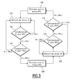
- the transceiver 22 of the electronic equipment transmits radio signals to the corresponding station 13A to 13N with the first transmission power level Pe1.
- the measurement software 30 then measures the reception power level Pr during step 105.
- step 110 the comparison software 30 compares the reception power level Pr measured in step 105 with the second threshold TPC2.
- the control software 34 returns to step 105.
- the control software 34 proceeds to step 115.
- step 115 the comparison software 30 compares the reception power level Pr measured in step 105 with the first threshold TPC1.
- the control software 34 returns to step 105.
- reception power level Pr is greater than or equal to the first threshold TPC1, the control software 34 proceeds to step 120.
- step 120 the transceiver 22 of the electronic equipment 20 changes the transmission power level, and then transmits radio signals to the corresponding station 13A to 13N with the second transmission power level. Pe2.
- the control software 34 modifies the value of the transmission power level which becomes equal to the second transmission power level. Pe2 only if the reception power level Pr is greater than or equal to the first threshold TPC1.
- the reception power level is strictly lower than the first threshold TPC1, or a fortiori lower than the second threshold TPC2, the second threshold TPC2 being strictly lower than the first threshold TPC1, the value of the transmission power level is not modified by the control software 34, and remains equal to the first transmission power level Pe1.
- step 125 following the eventual passage of the value of the transmission power level to the second transmission power level Pe2, the measurement software 30 measures the reception power level Pr.
- step 130 the comparison software 30 compares the reception power level Pr measured in step 125 with the first threshold TPC1.
- the control software 34 returns to step 125.
- reception power level Pr is less than or equal to the first threshold TPC1, the control software 34 proceeds to step 135.
- step 135 the comparison software 30 compares the reception power level Pr measured in step 125 with the second threshold TPC2.
- the control software 34 returns to step 125.
- the control software 34 passes the step 100 during which the value of the transmission power level is changed, and is then positioned at the first level. of emission power Pe1.
- the control software 34 modifies the value of the transmission power level which becomes equal to the first transmission power level. Pe1 only if the reception power level Pr is less than or equal to the second threshold TPC2.
- the reception power level is strictly greater than the second threshold TPC2, or a fortiori higher than the first threshold TPC1, the first threshold TPC1 being strictly greater than the second threshold TPC2, the value of the transmission power level is not modified by the control software 34, and remains equal to the second transmission power level Pe2.
- step 135 When the condition tested in step 135 is verified, the process returns to the initial step 100, and the control of the transmission level by the transceiver 22 is thus looped.
- the control method thus defined allows the electronic equipment to manage its transmission power level while maintaining a stable level of connection with a corresponding electronic station 13A to 13N, even in a dynamic environment, such as that of the railway vehicle. 11 in motion along the railroad track 12.
- the value of the transmission power level is modified ( and becomes equal to the second transmission power level Pe2) only if the reception power level Pr is greater than or equal to the first threshold TPC1.
- the value of the transmission power level is modified (and becomes equal to the first transmission power level Pe1) only if the reception power level Pr is less than or equal to the second threshold TPC2.
- the transmission power level is thus modified only in the event of a considerable variation in the reception power level Pr, for example when the reception power level Pr becomes greater than the first threshold TPC1, which has the highest value among the two. thresholds TPC1, TPC2, or when the reception power level Pr becomes lower than the second threshold TPC2, which has the smallest value among the two thresholds TPC1, TPC2.
- the control method is therefore not sensitive to slight variations in the reception power level Pr, unlike the control method of the state of the art.
- a flowchart of the control method according to a complementary aspect of the invention is illustrated on the figure 4 .
- control method further comprises a step 103 in which the control software 34 initializes to zero a first counter N1.
- the control software 34 resets the first counter N1 when of step 107 and proceeds to step 105 of measuring the reception power level Pr.
- control software 34 proceeds to step 113.
- step 113 the comparison software 30 compares the first counter N1 with a first number of cycles threshold Nc1 corresponding to the minimum number of consecutive cycles during which the reception power level Pr must be greater than or equal to the second threshold. TPC2 for the control software 34 to change the transmission power level.
- control software 34 increments the first counter N1 by one unit during the step 114 and returns to step 105.
- control software 34 proceeds to step 115.
- control method further comprises a step 123 in which the control software 34 initializes to zero a second counter N2.
- the control software 34 If, during the step 130 of comparing the reception power level Pr with the first threshold TPC1, the reception power level Pr is strictly greater than the first threshold TPC1, the control software 34 resets the second counter N2 when of step 127 and proceeds to step 125 of measuring the reception power level Pr.
- control software 34 proceeds to step 133.
- step 133 the comparison software 30 compares the second counter N2 with a second number of cycles Nc2 threshold corresponding to the minimum number of consecutive cycles during which the reception power level Pr must be less than or equal to the first threshold TPC1 for the control software 34 to change the transmission power level.
- control software 34 increments the second counter N2 by one unit during the step 134 and returns to step 125.
- control software 34 proceeds to step 135.
- step 105 is started at each cycle of transmitting radio signals by the corresponding electronic stations 13A to 13N when the transceiver 22 transmits radio signals with the first emission power level Pe1 .
- step 125 is started at each radio signal transmission cycle by the corresponding electronic stations 13A-13N when the transceiver 22 transmits radio signals with the second transmission power level Pe2.
- the periodicity of these cycles is for example substantially equal to 25 ms.
- each of the first threshold number of cycles Nc1 and the second threshold of number of cycles Nc2 is chosen between 1 and 40, preferably between 1 and 12.
- the change of the transmission power level to the second transmission power level Pe2 only occurs when the step 110 for comparing the reception power level Pr with the second threshold TPC2 indicates Nc1 consecutive times that the reception power level Pr is greater than or equal to the second threshold TPC2.
- the change of the transmission power level to the first transmission power level Pe1 occurs only when the step 130 for comparing the reception power level Pr with the first threshold TPC1 indicates Nc2 times consecutive that the reception power level Pr is less than or equal to the first threshold TPC1.
- Such fluctuations correspond in particular to fading of the radio signal occurring when, for example, the railway vehicle 11 enters a tunnel.
- this complementary aspect of the invention makes it possible to stabilize the level of transmission power during abrupt fluctuations in the reception power level Pr.
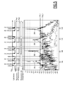
- the figure 5 illustrates the management of the transmission power level by the electronic equipment 20 implemented by the control method according to the invention when the vehicle 11 moves along the railway line 12 near the stations 13A, 13B, 13C and 13D.
- the curve 201 corresponds to the reception power level Pr of radio signals emitted by the station 13A, measured during the steps 105 and 125 of the method, the curve 202 to that of the reception power Pr of radio signals emitted by the station 13B, the curve 203 to that of reception power Pr of radio signals emitted by the station 13C, and the curve 204 to that of reception power Pr of radio signals emitted by the station 13D.
- Trigger which is “armed” when the reception power level Pr is between the two thresholds TPC1 and TPC2, and is “triggered” when the reception power level Pr is lower. at the second TPC2 threshold or higher than the first TPC1 threshold.
- the triggering of the trigger corresponds to a change in the power level of emission.
- the transceiver 22 transmits radio signals with the first transmit power level Pe1, the trigger is triggered.
- the trigger is armed.
- the trigger is triggered and the transceiver 22 begins transmitting radio signals with the second transmission power level Pe2.
- the trigger is armed again.
- the trigger is triggered and the transceiver 22 begins transmitting radio signals with the first transmission power level Pe1.
Landscapes
- Engineering & Computer Science (AREA)
- Computer Networks & Wireless Communication (AREA)
- Signal Processing (AREA)
- Mobile Radio Communication Systems (AREA)
- Transceivers (AREA)
Priority Applications (1)
| Application Number | Priority Date | Filing Date | Title |
|---|---|---|---|
| RS20210410A RS61690B1 (sr) | 2013-08-09 | 2014-08-08 | Metod kontrole elektronskog uredjaja, odgovarajući elektronski uredjaj i sistem |
Applications Claiming Priority (1)
| Application Number | Priority Date | Filing Date | Title |
|---|---|---|---|
| FR1357920A FR3009664B1 (fr) | 2013-08-09 | 2013-08-09 | Procede de pilotage d'un equipement electronique, equipement electronique et systeme de communication associes |
Publications (2)
| Publication Number | Publication Date |
|---|---|
| EP2836033A1 true EP2836033A1 (de) | 2015-02-11 |
| EP2836033B1 EP2836033B1 (de) | 2021-01-13 |
Family
ID=49780049
Family Applications (1)
| Application Number | Title | Priority Date | Filing Date |
|---|---|---|---|
| EP14180386.6A Active EP2836033B1 (de) | 2013-08-09 | 2014-08-08 | Verfahren zur Steuerung einer elektronischen Vorrichtung, entsprechende elektronische Vorrichtung und System |
Country Status (8)
| Country | Link |
|---|---|
| US (1) | US9332500B2 (de) |
| EP (1) | EP2836033B1 (de) |
| CN (1) | CN104348507B (de) |
| BR (1) | BR102014019811B1 (de) |
| CA (1) | CA2858497C (de) |
| FR (1) | FR3009664B1 (de) |
| IN (1) | IN2014DE02235A (de) |
| RS (1) | RS61690B1 (de) |
Cited By (1)
| Publication number | Priority date | Publication date | Assignee | Title |
|---|---|---|---|---|
| EP3454591A1 (de) * | 2017-09-11 | 2019-03-13 | ALSTOM Transport Technologies | Datenübertragungsverfahren eines schienenkommunikationssystems, entsprechendes computerprogramm, entsprechende kommunikationsausrüstung und entsprechendes schienenkommunikationssystem |
Citations (4)
| Publication number | Priority date | Publication date | Assignee | Title |
|---|---|---|---|---|
| US20050128970A1 (en) * | 2003-12-16 | 2005-06-16 | Intel Corporation | Systems and methods for adjusting transmit power in wireless local area networks |
| US20050138671A1 (en) * | 2003-12-22 | 2005-06-23 | Love Robert T. | Apparatus and method for adaptive broadcast transmission |
| US7577415B1 (en) * | 1999-06-14 | 2009-08-18 | Alereon, Inc. | Method and apparatus for ultra wideband power control |
| US20130170420A1 (en) * | 2010-10-07 | 2013-07-04 | Panasonic Corporation | Wireless communication device, wireless communication method and processing circuit |
Family Cites Families (1)
| Publication number | Priority date | Publication date | Assignee | Title |
|---|---|---|---|---|
| JP5520207B2 (ja) * | 2010-12-14 | 2014-06-11 | 京セラ株式会社 | 通信装置及び通信方法 |
-
2013
- 2013-08-09 FR FR1357920A patent/FR3009664B1/fr not_active Expired - Fee Related
-
2014
- 2014-08-05 CA CA2858497A patent/CA2858497C/fr active Active
- 2014-08-06 IN IN2235DE2014 patent/IN2014DE02235A/en unknown
- 2014-08-08 US US14/455,405 patent/US9332500B2/en active Active
- 2014-08-08 RS RS20210410A patent/RS61690B1/sr unknown
- 2014-08-08 EP EP14180386.6A patent/EP2836033B1/de active Active
- 2014-08-11 CN CN201410392666.6A patent/CN104348507B/zh active Active
- 2014-08-11 BR BR102014019811-3A patent/BR102014019811B1/pt active IP Right Grant
Patent Citations (4)
| Publication number | Priority date | Publication date | Assignee | Title |
|---|---|---|---|---|
| US7577415B1 (en) * | 1999-06-14 | 2009-08-18 | Alereon, Inc. | Method and apparatus for ultra wideband power control |
| US20050128970A1 (en) * | 2003-12-16 | 2005-06-16 | Intel Corporation | Systems and methods for adjusting transmit power in wireless local area networks |
| US20050138671A1 (en) * | 2003-12-22 | 2005-06-23 | Love Robert T. | Apparatus and method for adaptive broadcast transmission |
| US20130170420A1 (en) * | 2010-10-07 | 2013-07-04 | Panasonic Corporation | Wireless communication device, wireless communication method and processing circuit |
Cited By (2)
| Publication number | Priority date | Publication date | Assignee | Title |
|---|---|---|---|---|
| EP3454591A1 (de) * | 2017-09-11 | 2019-03-13 | ALSTOM Transport Technologies | Datenübertragungsverfahren eines schienenkommunikationssystems, entsprechendes computerprogramm, entsprechende kommunikationsausrüstung und entsprechendes schienenkommunikationssystem |
| FR3071125A1 (fr) * | 2017-09-11 | 2019-03-15 | Alstom Transport Technologies | Procede de transmission de donnees d'un syteme de communication ferroviaire, produit programme d'ordinateur, equipement de communication et systeme de communication ferroviaire associes |
Also Published As
| Publication number | Publication date |
|---|---|
| US9332500B2 (en) | 2016-05-03 |
| FR3009664A1 (fr) | 2015-02-13 |
| US20150045086A1 (en) | 2015-02-12 |
| CA2858497C (fr) | 2023-01-10 |
| CN104348507A (zh) | 2015-02-11 |
| RS61690B1 (sr) | 2021-05-31 |
| CA2858497A1 (fr) | 2015-02-09 |
| BR102014019811A2 (pt) | 2015-11-17 |
| EP2836033B1 (de) | 2021-01-13 |
| CN104348507B (zh) | 2018-07-06 |
| FR3009664B1 (fr) | 2016-12-23 |
| IN2014DE02235A (de) | 2015-06-19 |
| BR102014019811B1 (pt) | 2022-10-11 |
Similar Documents
| Publication | Publication Date | Title |
|---|---|---|
| EP2199826B1 (de) | Erfassungsverfahren eines Zielobjekts für ein Kraftfahrzeug | |
| US20180020398A1 (en) | Estimating a relative difference between signal strengths of wireless signals received by a device | |
| WO2020212150A1 (fr) | Procédé de prédiction d'une modification des conditions d'attachement d'un terminal à un réseau cellulaire | |
| EP2836033B1 (de) | Verfahren zur Steuerung einer elektronischen Vorrichtung, entsprechende elektronische Vorrichtung und System | |
| CA2580400A1 (fr) | Systeme et procede de verification de l'integrite d'un train | |
| FR2973515A1 (fr) | Systeme et procede permettant de detecter une deterioration ou une coupure dans un cable transportant des signaux | |
| CA3162243C (fr) | Procede et systeme d'auto-localisation a partir d'ondes radioelectriques, programme et support de programme correspondants | |
| FR3100683A1 (fr) | Procede de transferts intercellulaires | |
| EP3743778B1 (de) | Leistungsverbesserung von elektronischen vorrichtungen | |
| FR3071106B1 (fr) | Procede de detection d'accrochage d'une antenne a une cible par un lobe secondaire de cette antenne, produit programme d'ordinateur et module associes | |
| CN112804727A (zh) | 浮动lpwan中基于姿态感知的信道接入方法和装置 | |
| EP0996240B1 (de) | Methode zur Steuerung der Leistung welche in einem Telekommunikationssystem von einem Empfänger empfangen und von einem Sender gesendet wird, mit einem geschlossenen Regelkreis | |
| FR3109007A1 (fr) | Méthodes et systèmes pour la supervision de la distance inter-navettes autonomes sur un itinéraire | |
| FR3099679A1 (fr) | Procédé, dispositif et système de communication pour véhicule utilisant des radars | |
| FR3099669A1 (fr) | Procédé et dispositif d’adaptation de la puissance émise par une antenne de véhicule | |
| FR3081270A1 (fr) | Methodes et systemes de localisation et de radioguidage en environnements non cooperatifs | |
| FR3140430A1 (fr) | Procédé de caractérisation de la qualité d’un lien radio entre un véhicule et un équipement au sol | |
| EP3538912B1 (de) | Verfahren zur übertragung eines signals von einer sendevorrichtung an einen nicht-geosynchronen satelliten | |
| CN120186559A (zh) | 车辆信号的控制方法及装置、车辆、存储介质 | |
| WO2026052448A1 (fr) | Procédé d'amélioration du fonctionnement d'un dispositif récepteur d'un réseau de communications | |
| FR3098925A1 (fr) | Procédé et dispositif de détermination de la position d’un véhicule | |
| WO2022106445A1 (fr) | Methode d'optimisation du transfert intercellulaire dans un reseau mobile et systeme associe | |
| FR3099831A1 (fr) | Système et méthode de géolocalisation d’au moins un objet connecté | |
| FR3104350A1 (fr) | Procédé et dispositif de détection d’interférence radio pour véhicule | |
| WO2011083269A1 (fr) | Procede de localisation d'une source perturbatrice d'un signal dans le domaine de la radionavigation |
Legal Events
| Date | Code | Title | Description |
|---|---|---|---|
| PUAI | Public reference made under article 153(3) epc to a published international application that has entered the european phase |
Free format text: ORIGINAL CODE: 0009012 |
|
| 17P | Request for examination filed |
Effective date: 20140808 |
|
| AK | Designated contracting states |
Kind code of ref document: A1 Designated state(s): AL AT BE BG CH CY CZ DE DK EE ES FI FR GB GR HR HU IE IS IT LI LT LU LV MC MK MT NL NO PL PT RO RS SE SI SK SM TR |
|
| AX | Request for extension of the european patent |
Extension state: BA ME |
|
| R17P | Request for examination filed (corrected) |
Effective date: 20150811 |
|
| RBV | Designated contracting states (corrected) |
Designated state(s): AL AT BE BG CH CY CZ DE DK EE ES FI FR GB GR HR HU IE IS IT LI LT LU LV MC MK MT NL NO PL PT RO RS SE SI SK SM TR |
|
| RAP1 | Party data changed (applicant data changed or rights of an application transferred) |
Owner name: ALSTOM TRANSPORT TECHNOLOGIES |
|
| STAA | Information on the status of an ep patent application or granted ep patent |
Free format text: STATUS: EXAMINATION IS IN PROGRESS |
|
| 17Q | First examination report despatched |
Effective date: 20180413 |
|
| REG | Reference to a national code |
Ref country code: DE Ref legal event code: R079 Ref document number: 602014074175 Country of ref document: DE Free format text: PREVIOUS MAIN CLASS: H04W0052100000 Ipc: H04W0052240000 |
|
| RIC1 | Information provided on ipc code assigned before grant |
Ipc: H04W 84/12 20090101ALN20200624BHEP Ipc: H04W 84/00 20090101ALN20200624BHEP Ipc: H04W 52/24 20090101AFI20200624BHEP |
|
| GRAP | Despatch of communication of intention to grant a patent |
Free format text: ORIGINAL CODE: EPIDOSNIGR1 |
|
| STAA | Information on the status of an ep patent application or granted ep patent |
Free format text: STATUS: GRANT OF PATENT IS INTENDED |
|
| INTG | Intention to grant announced |
Effective date: 20200820 |
|
| GRAS | Grant fee paid |
Free format text: ORIGINAL CODE: EPIDOSNIGR3 |
|
| GRAA | (expected) grant |
Free format text: ORIGINAL CODE: 0009210 |
|
| STAA | Information on the status of an ep patent application or granted ep patent |
Free format text: STATUS: THE PATENT HAS BEEN GRANTED |
|
| AK | Designated contracting states |
Kind code of ref document: B1 Designated state(s): AL AT BE BG CH CY CZ DE DK EE ES FI FR GB GR HR HU IE IS IT LI LT LU LV MC MK MT NL NO PL PT RO RS SE SI SK SM TR |
|
| REG | Reference to a national code |
Ref country code: GB Ref legal event code: FG4D Free format text: NOT ENGLISH |
|
| REG | Reference to a national code |
Ref country code: CH Ref legal event code: EP |
|
| REG | Reference to a national code |
Ref country code: IE Ref legal event code: FG4D Free format text: LANGUAGE OF EP DOCUMENT: FRENCH |
|
| REG | Reference to a national code |
Ref country code: DE Ref legal event code: R096 Ref document number: 602014074175 Country of ref document: DE |
|
| REG | Reference to a national code |
Ref country code: AT Ref legal event code: REF Ref document number: 1355478 Country of ref document: AT Kind code of ref document: T Effective date: 20210215 |
|
| REG | Reference to a national code |
Ref country code: CH Ref legal event code: NV Representative=s name: NOVAGRAAF INTERNATIONAL SA, CH |
|
| REG | Reference to a national code |
Ref country code: GR Ref legal event code: EP Ref document number: 20210400880 Country of ref document: GR Effective date: 20210519 |
|
| REG | Reference to a national code |
Ref country code: AT Ref legal event code: MK05 Ref document number: 1355478 Country of ref document: AT Kind code of ref document: T Effective date: 20210113 |
|
| REG | Reference to a national code |
Ref country code: NL Ref legal event code: MP Effective date: 20210113 |
|
| REG | Reference to a national code |
Ref country code: LT Ref legal event code: MG9D |
|
| PG25 | Lapsed in a contracting state [announced via postgrant information from national office to epo] |
Ref country code: NL Free format text: LAPSE BECAUSE OF FAILURE TO SUBMIT A TRANSLATION OF THE DESCRIPTION OR TO PAY THE FEE WITHIN THE PRESCRIBED TIME-LIMIT Effective date: 20210113 Ref country code: NO Free format text: LAPSE BECAUSE OF FAILURE TO SUBMIT A TRANSLATION OF THE DESCRIPTION OR TO PAY THE FEE WITHIN THE PRESCRIBED TIME-LIMIT Effective date: 20210413 Ref country code: BG Free format text: LAPSE BECAUSE OF FAILURE TO SUBMIT A TRANSLATION OF THE DESCRIPTION OR TO PAY THE FEE WITHIN THE PRESCRIBED TIME-LIMIT Effective date: 20210413 Ref country code: PT Free format text: LAPSE BECAUSE OF FAILURE TO SUBMIT A TRANSLATION OF THE DESCRIPTION OR TO PAY THE FEE WITHIN THE PRESCRIBED TIME-LIMIT Effective date: 20210513 Ref country code: LT Free format text: LAPSE BECAUSE OF FAILURE TO SUBMIT A TRANSLATION OF THE DESCRIPTION OR TO PAY THE FEE WITHIN THE PRESCRIBED TIME-LIMIT Effective date: 20210113 Ref country code: FI Free format text: LAPSE BECAUSE OF FAILURE TO SUBMIT A TRANSLATION OF THE DESCRIPTION OR TO PAY THE FEE WITHIN THE PRESCRIBED TIME-LIMIT Effective date: 20210113 Ref country code: HR Free format text: LAPSE BECAUSE OF FAILURE TO SUBMIT A TRANSLATION OF THE DESCRIPTION OR TO PAY THE FEE WITHIN THE PRESCRIBED TIME-LIMIT Effective date: 20210113 |
|
| PG25 | Lapsed in a contracting state [announced via postgrant information from national office to epo] |
Ref country code: SE Free format text: LAPSE BECAUSE OF FAILURE TO SUBMIT A TRANSLATION OF THE DESCRIPTION OR TO PAY THE FEE WITHIN THE PRESCRIBED TIME-LIMIT Effective date: 20210113 Ref country code: PL Free format text: LAPSE BECAUSE OF FAILURE TO SUBMIT A TRANSLATION OF THE DESCRIPTION OR TO PAY THE FEE WITHIN THE PRESCRIBED TIME-LIMIT Effective date: 20210113 Ref country code: LV Free format text: LAPSE BECAUSE OF FAILURE TO SUBMIT A TRANSLATION OF THE DESCRIPTION OR TO PAY THE FEE WITHIN THE PRESCRIBED TIME-LIMIT Effective date: 20210113 Ref country code: AT Free format text: LAPSE BECAUSE OF FAILURE TO SUBMIT A TRANSLATION OF THE DESCRIPTION OR TO PAY THE FEE WITHIN THE PRESCRIBED TIME-LIMIT Effective date: 20210113 |
|
| PG25 | Lapsed in a contracting state [announced via postgrant information from national office to epo] |
Ref country code: IS Free format text: LAPSE BECAUSE OF FAILURE TO SUBMIT A TRANSLATION OF THE DESCRIPTION OR TO PAY THE FEE WITHIN THE PRESCRIBED TIME-LIMIT Effective date: 20210513 |
|
| REG | Reference to a national code |
Ref country code: DE Ref legal event code: R097 Ref document number: 602014074175 Country of ref document: DE |
|
| PG25 | Lapsed in a contracting state [announced via postgrant information from national office to epo] |
Ref country code: SM Free format text: LAPSE BECAUSE OF FAILURE TO SUBMIT A TRANSLATION OF THE DESCRIPTION OR TO PAY THE FEE WITHIN THE PRESCRIBED TIME-LIMIT Effective date: 20210113 Ref country code: CZ Free format text: LAPSE BECAUSE OF FAILURE TO SUBMIT A TRANSLATION OF THE DESCRIPTION OR TO PAY THE FEE WITHIN THE PRESCRIBED TIME-LIMIT Effective date: 20210113 Ref country code: EE Free format text: LAPSE BECAUSE OF FAILURE TO SUBMIT A TRANSLATION OF THE DESCRIPTION OR TO PAY THE FEE WITHIN THE PRESCRIBED TIME-LIMIT Effective date: 20210113 |
|
| PLBE | No opposition filed within time limit |
Free format text: ORIGINAL CODE: 0009261 |
|
| STAA | Information on the status of an ep patent application or granted ep patent |
Free format text: STATUS: NO OPPOSITION FILED WITHIN TIME LIMIT |
|
| PG25 | Lapsed in a contracting state [announced via postgrant information from national office to epo] |
Ref country code: SK Free format text: LAPSE BECAUSE OF FAILURE TO SUBMIT A TRANSLATION OF THE DESCRIPTION OR TO PAY THE FEE WITHIN THE PRESCRIBED TIME-LIMIT Effective date: 20210113 Ref country code: DK Free format text: LAPSE BECAUSE OF FAILURE TO SUBMIT A TRANSLATION OF THE DESCRIPTION OR TO PAY THE FEE WITHIN THE PRESCRIBED TIME-LIMIT Effective date: 20210113 Ref country code: ES Free format text: LAPSE BECAUSE OF FAILURE TO SUBMIT A TRANSLATION OF THE DESCRIPTION OR TO PAY THE FEE WITHIN THE PRESCRIBED TIME-LIMIT Effective date: 20210113 Ref country code: RO Free format text: LAPSE BECAUSE OF FAILURE TO SUBMIT A TRANSLATION OF THE DESCRIPTION OR TO PAY THE FEE WITHIN THE PRESCRIBED TIME-LIMIT Effective date: 20210113 |
|
| 26N | No opposition filed |
Effective date: 20211014 |
|
| PG25 | Lapsed in a contracting state [announced via postgrant information from national office to epo] |
Ref country code: AL Free format text: LAPSE BECAUSE OF FAILURE TO SUBMIT A TRANSLATION OF THE DESCRIPTION OR TO PAY THE FEE WITHIN THE PRESCRIBED TIME-LIMIT Effective date: 20210113 |
|
| PG25 | Lapsed in a contracting state [announced via postgrant information from national office to epo] |
Ref country code: SI Free format text: LAPSE BECAUSE OF FAILURE TO SUBMIT A TRANSLATION OF THE DESCRIPTION OR TO PAY THE FEE WITHIN THE PRESCRIBED TIME-LIMIT Effective date: 20210113 |
|
| PG25 | Lapsed in a contracting state [announced via postgrant information from national office to epo] |
Ref country code: MC Free format text: LAPSE BECAUSE OF FAILURE TO SUBMIT A TRANSLATION OF THE DESCRIPTION OR TO PAY THE FEE WITHIN THE PRESCRIBED TIME-LIMIT Effective date: 20210113 |
|
| REG | Reference to a national code |
Ref country code: BE Ref legal event code: MM Effective date: 20210831 |
|
| GBPC | Gb: european patent ceased through non-payment of renewal fee |
Effective date: 20210808 |
|
| PG25 | Lapsed in a contracting state [announced via postgrant information from national office to epo] |
Ref country code: IS Free format text: LAPSE BECAUSE OF FAILURE TO SUBMIT A TRANSLATION OF THE DESCRIPTION OR TO PAY THE FEE WITHIN THE PRESCRIBED TIME-LIMIT Effective date: 20210513 Ref country code: LU Free format text: LAPSE BECAUSE OF NON-PAYMENT OF DUE FEES Effective date: 20210808 |
|
| PG25 | Lapsed in a contracting state [announced via postgrant information from national office to epo] |
Ref country code: GB Free format text: LAPSE BECAUSE OF NON-PAYMENT OF DUE FEES Effective date: 20210808 Ref country code: BE Free format text: LAPSE BECAUSE OF NON-PAYMENT OF DUE FEES Effective date: 20210831 |
|
| PG25 | Lapsed in a contracting state [announced via postgrant information from national office to epo] |
Ref country code: HU Free format text: LAPSE BECAUSE OF FAILURE TO SUBMIT A TRANSLATION OF THE DESCRIPTION OR TO PAY THE FEE WITHIN THE PRESCRIBED TIME-LIMIT; INVALID AB INITIO Effective date: 20140808 |
|
| PG25 | Lapsed in a contracting state [announced via postgrant information from national office to epo] |
Ref country code: CY Free format text: LAPSE BECAUSE OF FAILURE TO SUBMIT A TRANSLATION OF THE DESCRIPTION OR TO PAY THE FEE WITHIN THE PRESCRIBED TIME-LIMIT Effective date: 20210113 |
|
| P01 | Opt-out of the competence of the unified patent court (upc) registered |
Effective date: 20230823 |
|
| PG25 | Lapsed in a contracting state [announced via postgrant information from national office to epo] |
Ref country code: MK Free format text: LAPSE BECAUSE OF FAILURE TO SUBMIT A TRANSLATION OF THE DESCRIPTION OR TO PAY THE FEE WITHIN THE PRESCRIBED TIME-LIMIT Effective date: 20210113 |
|
| PG25 | Lapsed in a contracting state [announced via postgrant information from national office to epo] |
Ref country code: MT Free format text: LAPSE BECAUSE OF FAILURE TO SUBMIT A TRANSLATION OF THE DESCRIPTION OR TO PAY THE FEE WITHIN THE PRESCRIBED TIME-LIMIT Effective date: 20210113 |
|
| PGFP | Annual fee paid to national office [announced via postgrant information from national office to epo] |
Ref country code: DE Payment date: 20250820 Year of fee payment: 12 |
|
| PGFP | Annual fee paid to national office [announced via postgrant information from national office to epo] |
Ref country code: GR Payment date: 20250822 Year of fee payment: 12 |
|
| PGFP | Annual fee paid to national office [announced via postgrant information from national office to epo] |
Ref country code: IT Payment date: 20250825 Year of fee payment: 12 |
|
| PGFP | Annual fee paid to national office [announced via postgrant information from national office to epo] |
Ref country code: FR Payment date: 20250829 Year of fee payment: 12 |
|
| PGFP | Annual fee paid to national office [announced via postgrant information from national office to epo] |
Ref country code: CH Payment date: 20250901 Year of fee payment: 12 |
|
| PGFP | Annual fee paid to national office [announced via postgrant information from national office to epo] |
Ref country code: IE Payment date: 20250820 Year of fee payment: 12 Ref country code: RS Payment date: 20250801 Year of fee payment: 12 |
|
| PG25 | Lapsed in a contracting state [announced via postgrant information from national office to epo] |
Ref country code: TR Free format text: LAPSE BECAUSE OF FAILURE TO SUBMIT A TRANSLATION OF THE DESCRIPTION OR TO PAY THE FEE WITHIN THE PRESCRIBED TIME-LIMIT Effective date: 20210113 |