EP2835897A2 - Brush assembly for an electric motor - Google Patents
Brush assembly for an electric motor Download PDFInfo
- Publication number
- EP2835897A2 EP2835897A2 EP14180375.9A EP14180375A EP2835897A2 EP 2835897 A2 EP2835897 A2 EP 2835897A2 EP 14180375 A EP14180375 A EP 14180375A EP 2835897 A2 EP2835897 A2 EP 2835897A2
- Authority
- EP
- European Patent Office
- Prior art keywords
- brush
- electric motor
- motor according
- holders
- card mount
- Prior art date
- Legal status (The legal status is an assumption and is not a legal conclusion. Google has not performed a legal analysis and makes no representation as to the accuracy of the status listed.)
- Granted
Links
- 238000003475 lamination Methods 0.000 description 22
- 239000002184 metal Substances 0.000 description 18
- 210000002105 tongue Anatomy 0.000 description 16
- 239000012212 insulator Substances 0.000 description 14
- 238000000034 method Methods 0.000 description 11
- 238000004804 winding Methods 0.000 description 9
- 238000001816 cooling Methods 0.000 description 3
- 239000000463 material Substances 0.000 description 3
- 239000000853 adhesive Substances 0.000 description 2
- 230000001070 adhesive effect Effects 0.000 description 2
- 230000002411 adverse Effects 0.000 description 2
- 230000000712 assembly Effects 0.000 description 2
- 238000000429 assembly Methods 0.000 description 2
- 230000000694 effects Effects 0.000 description 2
- 230000014759 maintenance of location Effects 0.000 description 2
- 230000000149 penetrating effect Effects 0.000 description 2
- 244000185238 Lophostemon confertus Species 0.000 description 1
- 238000004026 adhesive bonding Methods 0.000 description 1
- 230000005540 biological transmission Effects 0.000 description 1
- 238000003780 insertion Methods 0.000 description 1
- 230000037431 insertion Effects 0.000 description 1
- 238000009413 insulation Methods 0.000 description 1
- 238000004519 manufacturing process Methods 0.000 description 1
- 238000000465 moulding Methods 0.000 description 1
- 238000003466 welding Methods 0.000 description 1
Images


Classifications
-
- H—ELECTRICITY
- H02—GENERATION; CONVERSION OR DISTRIBUTION OF ELECTRIC POWER
- H02K—DYNAMO-ELECTRIC MACHINES
- H02K7/00—Arrangements for handling mechanical energy structurally associated with dynamo-electric machines, e.g. structural association with mechanical driving motors or auxiliary dynamo-electric machines
- H02K7/14—Structural association with mechanical loads, e.g. with hand-held machine tools or fans
- H02K7/145—Hand-held machine tool
-
- H—ELECTRICITY
- H01—ELECTRIC ELEMENTS
- H01R—ELECTRICALLY-CONDUCTIVE CONNECTIONS; STRUCTURAL ASSOCIATIONS OF A PLURALITY OF MUTUALLY-INSULATED ELECTRICAL CONNECTING ELEMENTS; COUPLING DEVICES; CURRENT COLLECTORS
- H01R39/00—Rotary current collectors, distributors or interrupters
- H01R39/02—Details for dynamo electric machines
- H01R39/38—Brush holders
- H01R39/381—Brush holders characterised by the application of pressure to brush
-
- H—ELECTRICITY
- H01—ELECTRIC ELEMENTS
- H01R—ELECTRICALLY-CONDUCTIVE CONNECTIONS; STRUCTURAL ASSOCIATIONS OF A PLURALITY OF MUTUALLY-INSULATED ELECTRICAL CONNECTING ELEMENTS; COUPLING DEVICES; CURRENT COLLECTORS
- H01R39/00—Rotary current collectors, distributors or interrupters
- H01R39/02—Details for dynamo electric machines
- H01R39/38—Brush holders
- H01R39/385—Means for mechanical fixation of the brush holder
-
- H—ELECTRICITY
- H02—GENERATION; CONVERSION OR DISTRIBUTION OF ELECTRIC POWER
- H02K—DYNAMO-ELECTRIC MACHINES
- H02K13/00—Structural associations of current collectors with motors or generators, e.g. brush mounting plates or connections to windings; Disposition of current collectors in motors or generators; Arrangements for improving commutation
- H02K13/10—Arrangements of brushes or commutators specially adapted for improving commutation
-
- H—ELECTRICITY
- H02—GENERATION; CONVERSION OR DISTRIBUTION OF ELECTRIC POWER
- H02K—DYNAMO-ELECTRIC MACHINES
- H02K3/00—Details of windings
- H02K3/32—Windings characterised by the shape, form or construction of the insulation
- H02K3/38—Windings characterised by the shape, form or construction of the insulation around winding heads, equalising connectors, or connections thereto
-
- H—ELECTRICITY
- H02—GENERATION; CONVERSION OR DISTRIBUTION OF ELECTRIC POWER
- H02K—DYNAMO-ELECTRIC MACHINES
- H02K3/00—Details of windings
- H02K3/46—Fastening of windings on the stator or rotor structure
- H02K3/52—Fastening salient pole windings or connections thereto
- H02K3/527—Fastening salient pole windings or connections thereto applicable to rotors only
-
- H—ELECTRICITY
- H02—GENERATION; CONVERSION OR DISTRIBUTION OF ELECTRIC POWER
- H02K—DYNAMO-ELECTRIC MACHINES
- H02K5/00—Casings; Enclosures; Supports
- H02K5/04—Casings or enclosures characterised by the shape, form or construction thereof
- H02K5/14—Means for supporting or protecting brushes or brush holders
- H02K5/143—Means for supporting or protecting brushes or brush holders for cooperation with commutators
- H02K5/148—Slidably supported brushes
-
- H—ELECTRICITY
- H02—GENERATION; CONVERSION OR DISTRIBUTION OF ELECTRIC POWER
- H02K—DYNAMO-ELECTRIC MACHINES
- H02K7/00—Arrangements for handling mechanical energy structurally associated with dynamo-electric machines, e.g. structural association with mechanical driving motors or auxiliary dynamo-electric machines
- H02K7/08—Structural association with bearings
- H02K7/085—Structural association with bearings radially supporting the rotary shaft at only one end of the rotor
-
- H—ELECTRICITY
- H02—GENERATION; CONVERSION OR DISTRIBUTION OF ELECTRIC POWER
- H02K—DYNAMO-ELECTRIC MACHINES
- H02K9/00—Arrangements for cooling or ventilating
- H02K9/02—Arrangements for cooling or ventilating by ambient air flowing through the machine
- H02K9/04—Arrangements for cooling or ventilating by ambient air flowing through the machine having means for generating a flow of cooling medium
- H02K9/06—Arrangements for cooling or ventilating by ambient air flowing through the machine having means for generating a flow of cooling medium with fans or impellers driven by the machine shaft
-
- H—ELECTRICITY
- H02—GENERATION; CONVERSION OR DISTRIBUTION OF ELECTRIC POWER
- H02K—DYNAMO-ELECTRIC MACHINES
- H02K9/00—Arrangements for cooling or ventilating
- H02K9/28—Cooling of commutators, slip-rings or brushes e.g. by ventilating
-
- H—ELECTRICITY
- H02—GENERATION; CONVERSION OR DISTRIBUTION OF ELECTRIC POWER
- H02K—DYNAMO-ELECTRIC MACHINES
- H02K5/00—Casings; Enclosures; Supports
- H02K5/04—Casings or enclosures characterised by the shape, form or construction thereof
- H02K5/18—Casings or enclosures characterised by the shape, form or construction thereof with ribs or fins for improving heat transfer
Definitions
- the present disclosure relates to a brush assembly for electric motors, and more particularly to a brush assembly for motors used in electric power tools and to power tools including the same.
- Known portable power tools typically have an electric motor received within a tool housing.
- One common type of electric motor used in power tools has a rotor, a stator, and brushes.
- the rotor includes a rotor shaft, laminations mounted on the rotor shaft, armature windings wound in slots in the lamination stack, and a commutator mounted on the rotor shaft and electrically connected to the armature windings.
- the stator may have field windings wound in laminations, or may have permanent magnets.
- the brushes are mounted in brush housings, often known as brush boxes or brush holders, in sliding electrical contact with the commutator. Electric current is supplied from a power source through the brushes to the commutator, and from the commutator to the armature windings.
- the brushes and brush holders are typically part of a brush assembly(ies).
- the brush holders and brushes are disposed diametrically opposite to each other with the commutator disposed therebetween.
- the brush assembly(ies) includes springs that urge the brushes against the commutator.
- Exemplary brush assemblies may utilize two or four brushes around the commutator.
- Conventional brush holder designs often include a brush card mount that is made of a plastic material and the brush holders mounted on a top surface of the brush card mount.
- the brush holders are typically formed by stamping and folding a metal sheet formed to encase the four sides of the brush. While this process is easy to use, the outer surface area provided by the brush holder is often too small to efficiently transfer heat away from the brushes.
- Some other conventional designs include brush holders which do not fully encase the brush, with open channels for air circulation between the brush holder and the brush. Such designs, however, expose the brushes to debris from the air flow without the desired increased cooling effect.
- an electric motor comprising a stator; an armature rotatably received within the stator, the armature having an armature shaft on which a commutator is mounted; and a brush assembly disposed around the commutator and defining a first surface facing the stator and a second surface opposite the first surface, the brush assembly comprising: a brush card mount; a plurality of brushes in sliding contact with the commutator to supply electric current to the commutator; and a plurality of thermally-conductive brush holders disposed on the second surface of the brush assembly to house the plurality of brushes and secured to the brush card mount, each brush holder including a plurality of projections formed along a length of an outer surface of the brush holder to increase a total surface area of the brush holder and transfer heat away from the brush holder.
- each of the brush holders includes a base portion securely attached to the brush card mount and disposed to house a bottom surface of the brush, and a main body attached to the base portion to house side surfaces and a top surface of the brush.
- the projections are disposed on at least one of a top surface and/or side surfaces of the main body. In an embodiment, at least six projections are provided.
- the brush card mount includes openings and the brush holders are partially disposed within the openings. Furthermore, the openings may extend to an outer periphery of the brush assembly. Preferably, the brush holders are slidingly received within the openings from the periphery of the brush assembly in a radial direction. Advantageously, the base portions of the brush holders are securely disposed within the openings.
- the brush card mount includes separate planar pieces separated by the plurality of openings and the base portions of the brush holders are slidingly received within the openings and supported by the separate planar pieces of the brush card mount.
- each brush holder includes grooves on both sides thereon and the planar pieces include side guides on both sides thereon arranged to mate with the grooves of the brush holder as the brush holder is received inside the opening of the brush card mount.
- the grooves of the brush holder are formed between two adjacent projections and press-fitted onto the guides of the planar pieces.
- the base portions of the brush holders are exposed on the first surface of the brush assembly to transfer heat away from the brushes through the first surface of the brush assembly.
- the main body and the base portion of the brush holders are integrally formed as a single piece.
- the projections are substantially perpendicular to the main body.
- four brush holders are disposed equidistantly around a periphery of the brush card mount.
- a power tool including an electric motor as set out above.
- the above-described embodiments substantially improve heat transfer from the brushes and brush holders by increasing the total surface area of the brush holders. This arrangement thus improves heat transfer from the brushes through the brush holders.
- FIGs. 1A and 1B depict perspective side views of a four-pole brush assembly (also referred to herein as brush card) 100, according to a first embodiment of the invention.
- Figs. 2 and 3 respectively depict top and bottom views of the four-pole brush card 100.
- brush card 100 includes a brush card mount 102 and four brush holders 104.
- the brush card mount 102 has a substantially circular circumference and the four brush holders 104 are arranged equidistantly on four sides of the brush card mount 102.
- Each brush holder 104 accommodates a brush 106 therein.
- the brushes 106 housed in brush holders 104 facing each other are electrically connected to one another, as discussed below.
- each brush holder 104 Both ends of each brush holder 104 are open to allow radial movement of the brush 106 towards and away from the centre of the brush card 100.
- the brush card mount 102 includes upright posts 108 in close proximity to the brush holders 104. Each post 108 is arranged to hold a wound portion of a spring 110.
- Each spring 110 includes an extended arm that engages a back surface of brush 106 inside the brush holder 104 to bias the brush 106 towards the centre of the brush card 100.
- Brush card mount 102 includes a planar portion, to which brush holders 104 are secured. A middle section of the planar portion includes an opening that receives a motor commutator (not shown).
- the brush card mount 102 also includes a bridge portion 112 arranged above the commutator opening (and the commutator) and connected to the planar portion via four bridge legs 114a, 114b, 116a, and 116b.
- Bridge legs 114a, 114b, 116a, and 116b extend longitudinally (i.e., in the direction of the motor, at a substantially right angle with respect to the plane of the brush card mount 102) from the planar portion to the bridge portion 112.
- Radially formed between bridge legs 114a, 114b, 116a, and 116b are gaps that allow for the radial movement of brushes 106.
- Bridge legs 114a and 114b form walls that extend radially from the bridge portion 112 to (or near) outer edges of the brush card mount 102.
- the bridge legs 116a and 116b similarly extend towards (or near) outer edges of the brush card mount 102. This arrangement strengthens support for the bridge portion 112.
- bridge leg 114a mechanically supports and electrically isolates two terminals 118a and 118b provided on both sides of its outward-extending wall. Terminals 118a and 118b are connected to metal routings 120a and 120b, which extend over the bridge portion 112 to bridge leg 114b.
- Metal routings 120a and 120b connect the brushes 106 facing each other to one of the terminals 118a and 118b.
- metal routings 120a and 120b are connected via wires 122 to either corresponding brush holders 104 or brushes 106 via wires 120.
- metal routings 120a, 120b are routed around a shaft bearing pocket 126, which holds a shaft bearing 136, as discussed below in detail.
- metal routing120a crosses over routing 120b to allow for opposite brushes 106/brush holders 104 to be connected to the same terminal 118a or 118b.
- Fig. 4 depicts a perspective expanded view of brush card 100, wherein brush card mount 102 is depicted separately from the rest of the brush card 100 components.
- the bridge portion 112 of the brush card mount 102 includes channels 124a, 124b that accommodate metal routings 120a, 120b. Each of the channels 124a, 124b extends from leg 114a to leg 114b, around shaft bearing pocket 126.
- Metal routings 120a, 120b include vertically-extending teethed ends 132a, 132b on both ends, arranged to get pushed into slots 134 of bridge legs 114a, 114b during the assembly process. It is noted that other means such as an adhesive or molding may be used to secure the metal routings 120a, 120b to the bridge portion 112.
- Terminals 118a and 118b integrally extend from the routings 120a and 120b above the teethed ends 132a and 132b on the two sides of leg 114a.
- Channel 124b includes a recessed portion 128 that penetrates into bridge portion 112 between the shaft bearing pocket 126 and the bridge leg 114b.
- the recessed portion 128 is substantially vertical.
- the channel 124b extends out through the bridge portion 112 from the end of the recessed portion 128 along a lower plane.
- the recessed portion 128 intersects a portion of channel 124a.
- Metal routing 120b includes a penetrating portion 130 that is received inside the recessed portion 128 of channel 124b.
- the penetrating portion 130 is substantially vertical. This allows routing 120a to cross over metal routing 120b as it extends through channel 124a to bridge leg 114b. This arrangement creates a gap between the metal routings 120a and 120b that, in this embodiment, is 1-3 mm. This gap is sufficient to prevent an electrical shortage.
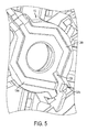
- Fig. 5 depicts a zoomed-in view of the bridge portion 112 showing the channels 124a and 124b and the recessed portion 128 within the channel 124b.
- FIG. 6A depicts a rear perspective view of the brush card mount 102 prior to the bearing 136 being inserted and heat-staked.
- the brush card mount 102 includes a plastic ring 138 around the back side of the pocket 126. Plastic ring 138 slightly projects from a rear surface of the bridge portion 112.
- Fig. 6B depicts a rear perspective view of the brush card mount 102 after the bearing 136 is inserted into the bearing pocket 126 and heat-staked.
- the plastic ring 138 is heated to deform around the circumference of the rear surface of the shaft bearing 136.
- the plastic ring 138 in this manner folds inwardly to contain the bearing 136. This secures the bearing 136 inside the pocket 126. Accordingly, the remaining components of the brush card 100 are assembled on the brush card mount 102 after the heat-staking is completed. Once brush card 100 is fully assembled, the bearing 136 is press-fitted onto the motor shaft (not shown) during motor assembly.
- Fig. 7A depicts a front perspective view of a four-pole brush card 200, according to a second embodiment of the present invention.
- Fig. 7B depicts a rear perspective view of the brush card mount 202 of the brush card 200, according to the second embodiment.
- Fig. 7C depicts a perspective view of the brush card mount 202, according to the second embodiment.
- the top of the bridge portion 212 does not include an opening as in the previous embodiment.
- pocket 226 of the brush card mount 202 is not open-ended. Instead, pocket 226 encloses the top end of the shaft bearing 236.
- Metal routings 220a, 220b extend in parallel over the bridge portion 212.
- the pocket 226 includes one or more pins 228 inserted through two through-holes that extend into the pocket 226 within the bridge portion 212.
- the through-holes are positioned to place a portion of the pins 226 inside the pocket 226, as shown in Fig. 7B .
- the shaft bearing 236 includes a groove 238 formed on its outer surface.
- the groove 238 has the same width as the pins 226. As the shaft bearing 236 is forced inside the pocket 226, it slides past the pins 228 until the pins 228 are locked inside the groove 238.
- the shaft bearing 236 is first placed inside the pocket 226 and the pins 228 are then inserted through the grooves 238.
- the pins 228 securely hold the shaft bearing 236 inside the pocket 226.
- any retention mechanism e.g., an E-clip, a C-clip, a single piece U-shaped retainer, a split ring, etc., may be used to retain the shaft bearing 236, as will be appreciated by those skilled in the art.
- Fig. 8 depicts a rear perspective view of a known conventional brush assembly 300 including a brush card mount 302, brush holders 304, and brushes 306.
- Brush holders 304 are mounted on a top surface of the brush card mount 302.
- Brush holders 304 include legs 308 that penetrate through openings, or around the edges of the brush card mount 302 and crimp on the rear side of the brush card mount 302.
- Brush holders 304 may be provided as single piece or multi-piece units.
- the brush card 300 is arranged around a motor commutator, with the rear surface of the brush card 300 facing the motor stator and fan.
- the top surface of the brush card 300 i.e., where the brush holders 304 are located
- Brush holders 304 generate a substantial amount of heat resulting from the electrical current passing through the brushes 306.
- Air flows around the brush holders 304, through the opening in the brush card 300 and around the outer circumference of the brush card 300, into the fan. While the air flow cools the brush holders 304 to some degree, the cooling effect of the air flow in this conventional design is not sufficient in many power tool designs, in particular in high power applications. What is needed is a more effective cooling mechanism for the brush assembly.
- Brush card mount 102 includes four openings 140 for receiving the brush holders 104 through its rear surface. This results in brush holders 104 occupying a large portion of the surface area of the rear surface of the brush card 100 adjacent the motor fan. Thus, brush holders 104 act as heat sinks to transfer heat away from the brush card 100. This design significantly improves heat transfer as compared to the conventional design discussed above with reference to Fig. 8 .
- each opening 140 of the brush card mount 102 is defined by two recessed surfaces 142 of the brush card mount 102 on its sides and a boundary portion 144 of the brush card mount 102 on its radial end.
- the recessed surfaces 142 each include two slots 146.
- the brush holders 104 each include a base piece 150 and a main piece 160, according to an embodiment.
- the base piece 150 in this embodiment includes a flat portion 152 and two side portions 156.
- Flat portion 152 includes two rectangular slots 154.
- Side portions 156 each include two upwardly-projecting legs 158.
- the main piece 160 includes a brush-holder portion 162 that is shaped to contain two side surfaces and a top surface of the brush 106. Extending from side ends the brush-holder portion 162 are two flat portions 166 that extend parallel with the rear surface of the brush card mount 102. The flat portions 166 each include two slots 168 that correspond to and receive upwardly-projecting legs 158 of the base piece 150. In addition, the brush-holder portion 162 includes two downward protrusions 164 that correspond to and are received inside rectangular slots 154 of the base piece 150.
- the side surfaces of the brush-holder portion 162, include openings 170 that is open-ended on a distal end of the brush holder 104 and extends radially to accommodate the back and forth movement of the spring 110 and the wires 122.
- Figs. 9B and 9C depict steps of assembling the brush holder 104 into the brush card mount 102.
- the main piece 160 of the brush holder 104 is inserted into the opening 140 of the brush card mount 102.
- the top surfaces of the flat portions 166 mate with the recessed surfaces 142 of the bush card 102 around the opening 140.
- the brush holder portion 162 penetrates through the opening 140 and projects above the top surface of the brush card mount 102.
- Slots 168 of the main piece 160 in this position are aligned with slots 146 of the recessed surfaces 142.
- upwardly-projecting legs 158 of the base piece 150 are inserted through the aligned slots 168 of the main piece 160 and slots 146 of the recessed surfaces 142. Downward protrusions 164 are received inside the rectangular slots 154 as the base piece 150 comes in contact with the main piece 160. Side portions 156 of the base piece 150 mate with the back surfaces of the flat portions 166 of the main piece 160. Once this step is complete, the upwardly-projecting legs 158 are crimped as discussed below.
- Fig. 10 depicts a zoomed-in perspective view of the top surface of the brush card 100 showing the upwardly-projecting legs 158 crimped over the top surface of the brush card mount 102 within recessed pockets 172.
- Recessed pockets 172 each include two slanted surfaces (see Fig. 4 ) between the slots 146. Crimped portions of the upwardly-projecting legs 158 rest on these slanted surfaces once they are crimped.
- top surface of the boundary portion 144 of the brush card mount 102 is recessed to accommodate insertion of the brush 106 inside the brush holder 104 once the brush holder 104 assembly is complete. It is further noted that openings 170 of the brush holder 104 are arranged to accommodate the back and forth movement of the spring 110 and the wires 122 along with the brush 106.
- Figs. 11A through 11 D depict various views of the brush holder 104, including the base piece 150 and the main piece 160 crimped together.
- the brush card mount 102 is not shown in these figures. However, as discussed above, in the fully-assembled brush card 100, areas of the brush card mount 102 between recessed surfaces 142 and recessed pockets 172 are sandwiched between the crimp portions of the upwardly-projected legs 158 and the top surfaces of the flat portions 166 of the brush holders 104.
- the brush holder design of the invention discussed herein provides several advantages.
- the two-piece assembly of the brush holders into the brush card mount is relatively easy.
- the metallic base pieces 150 of the brush holders 104 are exposed in close proximity to the motor fan.
- the brush holders 104 thus act as heat sink to transfer heat away from the brush holders 104 and brushes 106.
- This arrangement substantially improved overall heat transfer from the brush card 100.
- Fig. 12 provides a rear perspective view of the brush card 100 and a cut-off portion of a motor fan 502.
- the brush holders 104 occupy at least 40% of the total surface area of the rear surface of the brush card 100.
- the brush holders 104 take up at least 45% of the total area of the surface area of the rear surface of the brush card 100. More preferably, the brush holders 104 take up at least 50% of the total area of the surface area of the rear surface of the brush card 100.
- the rear surface of the brush card 100 (including the brush card mount 102 and brush holders 104) acts as a baffle for the fan 502.
- FIG. 13A depicts a perspective view of a brush card 400, according to this embodiment.
- the brush card 400 includes a brush card mount 402 and brush holders 404.
- brush card mount 402 has a substantially circular periphery and the four brush holders 404 are arranged equidistantly around the periphery of the brush card mount 402.
- the brush holders 404 facing each other are electrically connected to one another.
- Each brush holder 404 houses a brush 406 therein. Both ends of each brush holder 404 are open to allow radial movement of the bush towards a centre of the brush card 400.
- the brush card mount 402 includes posts 408 in close proximity to the brush holders 404.
- the posts 408 accommodate springs 410, each of which includes an extended arm that engages a back portion of a corresponding brush 406 to bias the brush 406 towards the centre of the brush card 400.
- Metal routings 420a, 420b are disposed on (over or within) bridge portion 412 to connect brushes 406 that are arranged opposite each other. As in the previously-described embodiments, metal routings 420a, 420b cross over each other within bridge portion 412. Terminals 418a, 418b are disposed at the ends of the metal routings 420a, 420b. Wires 422 are also coupled between brushes 406 and the metal routings 420a, 420b.
- Fig. 13B depicts a perspective view of the brush card 400 without the brush holders 404.
- bridge portion 412 includes channels 424a, 424b formed therein for placement of metal routings 420a, 420b.
- a planar portion of the brush card mount 402 includes four separate planar pieces 411 connected together via legs 414 of bridge portion 412.
- the planar pieces 411 in this embodiment are not connected to one another along the main plane of the brush card mount 400. Instead, planar openings 416 between the planar pieces 414 receive the brush holders 404 in a radial direction.
- Planar pieces 411 include side guides 415 arranged to be received in corresponding grooves of the brush holders 404, as discussed below.
- Planar openings 416 may be open-ended on the outer end for receiving the brush holders 404, but close ended on the inner end to mechanically join the planar pieces 411 to one another.
- Planar openings 416 may be open-ended on the inner end for receiving the brush holders 404, but close ended on the outer end to mechanically join the planar pieces 411 to one another. Placing a ring on either the inner or outer circumferences of the planar pieces 411 to connect the planar pieces 411 together provides mechanical support for the brush card 400 and enhances the moldability of the planar pieces 411 during the manufacturing process.
- Figs. 14A and 14B depict perspective and cross-sectional views of the brush holder 404.
- Brush holder 404 includes a main body 450 and a base portion 452 formed together integrally as one piece.
- the main body 450 includes openings 470 for facilitating the back and forth movement of the springs 410 and the wires 422.
- the main body 450 includes side projections 454, which together with ends of the base portion 454 form grooves 462.
- Grooves 462 receive side guides 415 of the brush card mount 402 as the brush holders 404 slides into planar openings 416.
- the grooves 462 are press-fitted onto the guides 415.
- An adhesive is used to secure the guides 415 inside the grooves 462.
- a lower surface of the base portion 452 acts as a heat sink to carry heat away from the brush card 400, including the brush holder 404 and the brushes 406, similarly to the previous embodiment.
- the brush holder 404 includes projections 456, 458 projecting from the main body 450.
- Four side projections 456 and two top projections 458 are provided. Projections 456 and 458 increase the total surface area of the brush holder 404, thereby improving heat transfer away from the brush holder 404.
- projections 456, 458 shown in Figs. 14A and 14B are used with a single-piece brush holder design, the same projections may be incorporated into the two-piece design of Figs. 9A-12 to improve heat transfer.
- FIG. 15 depicts a partial cross-sectional view of a power tool 500 in this example a drill drives one half of the power tool housing 508 is shown for illustration purposes, though it is understood that the second half of the power tool housing includes more or less the same or similar features.
- the power tool 100 includes the brush card 100, including the brush card mount 102 and the brush holders 104, disposed at one end of the housing.
- Motor 510 includes a motor stator (i.e., can) 512, a rotor 514, and a commutator 516 rotatatably coupled to the rotor 514.
- the commutator 516 is disposed inside the brush card 100 between the four brushes 106.
- the fan 502 is also rotatably attached to the rotor 514.
- the operation of the motor 510 and its components is beyond the scope of this disclosure and is not discussed in further detail, but reference is made to U.S. Patent No. 7,126,242 as an example of such an electric motor.
- Figs. 16A-16C depict various perspective and side views of the fan 502.
- Fig. 17 depicts a zoomed-in view of the fan 502 inside the tool housing 508.
- fan 502 includes a plurality of blades 504 arranged between a first inner ring 520 and a second outer ring 522.
- the inner ring 520 is arranged to mate with the rotor 514, while the second ring 522 is disposed in the proximity of the brush card 100, as shown in Fig. 15 .
- Each fan blade 504 includes an inner edge 524 that extends from a first end 520a of the inner ring 520 towards the rear surface of the brush card 100.
- the inner edge 524 is inclined towards the armature 516 and the rotor 514 (i.e., at an angle to the longitudinal axis of the motor 510), though the inner edge 524 may be parallel to the tool housing in an alternative embodiment.
- Each fan blade 504 also includes an outer edge 526 that extends from the outer ring 522 towards the stator 512 substantially in parallel with the longitudinal axis of the motor 510.
- a first side edge 528 extends from a second end 520b of the inner ring 520 to the end of the outer edge 526. The first side edge 528 is arranged at an angle away from the stator 512 in the direction of the end of the outer edge 526.
- a second side edge 530 extends from the outer ring 522 to the end of the inner edge 524, substantially parallel to the rear surface of the brush card 100. However, the second side edge 530 may be inclined slightly towards the brush card 100 as it meets the inner edge 524.
- the outer surface of the inner ring 522 may include a slanted surface 532 that is arranged at an angle away from the brush card 100 in the direction of the outer edge 526. This slanted surface 532 may be arranged at at least a 45 degree angle with respect to the rear surface of the brush card 100. This arrangement helps reduce the length of the outer edge 526 of each blade 504 even further for more effective air flow generation.
- Fig. 18 depicts a cross-sectional view of the tool housing 508 including the brush card 100, without the motor 510 and the fan 502.
- Air inlets 542 and 544 are provided in the rear and centre portion of the power tool housing 508.
- the fan 502 rotates, it generates an air flow from front inlets 542 through the motor 510, in particular in the area between the stator 512 and the rotor 514, in an axial direction to cool the motor 510.
- the air is then redirected in a radial direction out of the power tool 500 through air vents 540 disposed in the tool housing 508 adjacent the fan 502.
- the fan generates an air flow from rear inlets 544 through the brush card 100, particularly around the brush holders 104, and through the area between brush holders 104 and the commutator 516, in an axial direction to cool the brush card 100.
- This air is also redirected in a radial direction out of the power tool 500 through the same air vents 540.
- the rear surface of the brush card 100 i.e., brush card mount 102 together with the brush holders 104) forms a baffle to contain the air flow inside the fan 502 and out of the vents 540.
- the end surface 513 of the stator 512 facing the fan 502 forms a second baffle for the fan 502.
- the angled surface of the first side edge 528 creates a gap between the stator 512 end surface baffle and the fan 502.
- the angled surface of the outer ring 522 creates a gap between the brush card 100 baffle and the fan 502.
- These gaps may adversely affect air flow through the fan 502.
- two ribs 534 and 536 corresponding to the slanted surface 532 of the outer ring 522 and the first side edge 528, respectively, are provided in the tool housing 508.
- the first rib 534 includes a sloped surface disposed in close proximity to and in parallel with the slanted surface 532 of the outer ring 522.
- the second rib 536 includes a sloped surface in close proximity to and in parallel with the first side edge 528 of the fan 501.
- Both ribs 534 and 536 also include surfaces that are in contact with the rear surface of the brush card 100 (including a portion of the brush holders 104 and the brush card mount 102) and the end surface 513 of the stator 512, respectively.
- the ribs 534 and 536 are both ringshaped and extend around the two housing halves to fully close the gaps between the housing 508 and the fan 502 created by the angled surfaces of the outer ring 522 and the first side edge 528.
- a combination of the rear surface of the brush card 100 (including the brush card mount 102 and the brush holders 104), and the sloped surface of the first rib 534, forms the first baffle for the fan 502.
- a combination of the end surface 513 of the stator 512 and the sloped surface of the second rib 536 forms the second baffle for the fan 502.
- the ribs 534 and 536 provide alignment features for placement of the brush card 100 and the stator 512 within the power tool housing 508.
- FIG. 19-21C A fourth embodiment of the invention is disclosed herein with reference to Figs. 19-21C , and with continued reference to Figs. 16A-16C .
- Fig. 19 depicts the fan 502 mounted on a fully wound and molded rotor 514.
- the rotor 514 includes a lamination stack 550, windings 552, and end insulators 560.
- End insulators 560 are disposed at the ends of the lamination stack 550 prior to the lamination stack 550 being wound.
- End insulators 560 provide insulation between the rotor windings and the rotor lamination stack 550 and protect the wires from being cut during the winding process.
- Fig. 20 depicts a perspective view of the same fan 502 and rotor 514 without the windings 552.
- the fan 502 is provided with a plurality of tongues 580, as shown in Figs. 16A, 16C , 19 and 20 .
- Tongues 580 project in the direction of the rotor 514 from the inner ring 520 of the fan 502.
- Tongues 580 may be 2-6 mm in length.
- Tongues 580 may be disposed equidistantly around the periphery of the inner ring 510.
- the number of tongues 580 may correspond to the number of slots in the lamination stack 550, although a lesser number of tongues 580 may be provided.
- End insulator 560 facing the fan 502 is provided with a plurality of notches 562 arranged to receive the tongues 580 of the fan 502, as discussed below in detail.
- Figs. 21A-21C depict perspective views of a rotor end insulator 560.
- End insulator 560 is pre-molded to include a base portion 564 shaped to match a cross-sectional profile of the lamination stack 550.
- the base portion 564 includes radially-extending slots 566 formed between teeth 558 of the base portion 564.
- the slots 566 and teeth 568 respectively correspond to the slots and teeth of the lamination stack 550.
- the teeth 568 extend outwardly along the circumference of the base portion 564 to partially close the outer end of the slots 566.
- the slots 566 of the base portion 564 have walls 570 projecting perpendicularly to the base portion 564 (in the longitudinal direction of the motor) on one side.
- the walls 570 are arranged to form-fittingly protrude into the slots of the lamination stack 550 to insulate the lamination stack teeth.
- the walls 570 may be, for example, 4 to 12 mm in depth.
- the base portion 564 includes a through-hole 572 at its center portion for accommodating the rotor shaft.
- Two end insulators 560 are form-fittingly mounted on the ends of the lamination stack 550. There may be a gap of, for example, 2 to 10 mm between the ends of the inner walls 570 of the two end insulators 560 within the lamination stack 550 slots. As the coils are wound into the lamination stack slots over the end insulators 560, the thickness of the walls 570 ensures that no contact is made between the coil and the lamination stack 560. Furthermore, the outer surface of the base portion 564 has a slanted profile near the outer ends of the teeth 568 that forces the coils to be packed tightly into the lamination stack slots.
- notches 562 are arranged at the outer ends of the teeth 568 on the periphery of the end insulator 560 to receive the tongues 580 of the fan 502.
- the notches 562 extend longitudinally through the entire length of the teeth 568. This arrangement allows the tongues 580 of the fan 502 to make direct contact with the end of the lamination stack 550. This reduces the tolerances associated with the motor over a comparable design in which the fan 502 is mounted on the end insulator 560.
- tongues 580 are mounted directly on the lamination stack 550, calculating the total tolerances for the fan 502 needs only take into account the tolerance levels of the fan 502 and the lamination stack 550, and not the tolerance levels of the end insulator 560, which is made of plastic and has a relatively large tolerance. It is noted that tongues 580 may be secured within the notches 562 form-fittingly, or via heat-taking, welding, adhesive-bonding, etc.
- the fan 502 may be further provided with one or more additional tongues 582 arranged on opposite ends of the inner ring 520.
- tongues 582 are longer than tongues 580 and are arranged to be received between two adjacent teeth of the lamination stack 550.
- Long tongues 582 are provided to ensure that tongues 580 are placed inside the notches 562, and not between the adjacent teeth of the lamination stack 550, during assembly.
- Fig. 22 depicts a spring 110, according to an embodiment.
- Spring 110 includes a wound portion 602, a first leg 604, and a second leg 606 that is longer than the first leg 604 and includes a hook 608 at its distal end.
- Fig. 23 depicts a partial perspective view of the brush card 100, according to an embodiment.
- the wound portion 602 of the spring 110 is arranged around the post 108 of the brush card mount 102.
- the hook 608 of the second leg 606 engages the back of the brush 106.
- the first leg 604 of the spring 110 engages a pocket 614 of the brush card mount 102.
- pockets 614 for each spring 110 are formed within end portions of the bridge legs 116a, 116b on both sides (e.g., close to the periphery of the brush card mount 102). The position of the first leg 604 within the pocket 614 allows the torsion spring 110 to be loaded as it engages the back of the brush 106.
- the first leg 604 is placed within the pocket 614 as the wound portion 602 is pushed down the post 108.
- the problem with this assembly process is that it is difficult to engage and move the second leg 606 after the wound portion 602 has been pushed down the post 108. This process is time consuming and burdensome.
- the end of the bridge legs 116a, 116b are each provided with an arcuate surface 612, as shown in Fig. 23 .
- Arcuate surface 612 is located above the pockets 614.
- a sloped surface 610 is provided extending from the top of the bridge leg 116a or 116b to the top of the arcuate surface 612.
- the hook 608 remains within the recess 622. Meanwhile, the end of the first leg 604 slides down the sloped surface 610 over the arcuate surface 612, and along the arcuate surface 612 until it snaps into the pocket 614. As the first leg 604 moves down the arcuate surface 612 it loads the torsion spring 110, so the spring 110 will be loaded even after the first leg 604 snaps into the pocket 614.
- Fig. 24 depicts a rear view of the brush card 100 showing the first leg 604 of the spring 110 inside the pocket 614.
- the pockets 614 for adjacent springs 110 are located under the arcuate surface 612, forming a mushroom-shaped cross-sectional profile.
- the arcuate surface 612 may be shaped as a half-circle above the pockets 614, although a cam surface may be utilized to optimize the movement of the first leg 604 into the pocket 614.
- brush 106 is shown inside the brush holder 104.
- the hook 608 of the spring 110 engages the recess 622 of the end portion 620 of the brush holder during the assembly process.
- the hook 608 and the second leg 606 are pulled down to engage the rear surface of the brush 106.
- the rear surface of the brush 106 includes two humped surfaces 624 and 626 and a groove 628 therebetween.
- the rear surface of the brush 106 is designed and arranged such that, after the motor is assembled and the commutator is placed inside the brush card 100, a portion of the humped surface 624 is aligned with a lower end of the recess 622.
- the recess 622 includes a slanted lower end 622a which, as viewed from the side, ends in alignment with (or slightly above) the humped surface 624.
- the second leg 606 of the spring 110 is simply pushed down. As the second leg 606 is pushed down, the hook 608 (or the second leg 606) slides down the slanted lower end 622 of the recess, onto and over the humped surface 624, and into the groove 628.
- This design substantially eases the assembly process.
- Each the humped surfaces 624 may be semi-circular shaped, although a cam surface may be utilized to optimize the movement of the hook 608 over the humped surface 624. It is also noted that two humped surfaces are shown in this embodiment to ease the assembly process, but the brush 106 may include a single humped surface above the groove 628.
Abstract
Description
- The present disclosure relates to a brush assembly for electric motors, and more particularly to a brush assembly for motors used in electric power tools and to power tools including the same.
- Known portable power tools typically have an electric motor received within a tool housing. One common type of electric motor used in power tools has a rotor, a stator, and brushes. The rotor includes a rotor shaft, laminations mounted on the rotor shaft, armature windings wound in slots in the lamination stack, and a commutator mounted on the rotor shaft and electrically connected to the armature windings. The stator may have field windings wound in laminations, or may have permanent magnets. The brushes are mounted in brush housings, often known as brush boxes or brush holders, in sliding electrical contact with the commutator. Electric current is supplied from a power source through the brushes to the commutator, and from the commutator to the armature windings.
- The brushes and brush holders are typically part of a brush assembly(ies). The brush holders and brushes are disposed diametrically opposite to each other with the commutator disposed therebetween. The brush assembly(ies) includes springs that urge the brushes against the commutator. Exemplary brush assemblies may utilize two or four brushes around the commutator.
- Generally, in brush assemblies, transmission of electric current across the sliding interface between the brushes and the motor commutator generates a considerable amount of heat. This heat is often associated with the material used in the brushes. Such materials have relatively higher electrical resistance in order to enhance desirable brush properties such as low friction coefficient and high durability. The heat is also generated from the electrical arcing that occurs when electrical switching occurs as the commutator and brushes rotate with respect to each other. It is desirable for this heat to be transferred away from the brushes and dissipated, for example by impinging air flow.
- Conventional brush holder designs often include a brush card mount that is made of a plastic material and the brush holders mounted on a top surface of the brush card mount. The brush holders are typically formed by stamping and folding a metal sheet formed to encase the four sides of the brush. While this process is easy to use, the outer surface area provided by the brush holder is often too small to efficiently transfer heat away from the brushes. Some other conventional designs include brush holders which do not fully encase the brush, with open channels for air circulation between the brush holder and the brush. Such designs, however, expose the brushes to debris from the air flow without the desired increased cooling effect.
- What is needed is a brush assembly design that enables more efficient heat transfer from the brushes through the brush holders.
- It is an object of the present invention to at least alleviate the aforementioned shortcomings. According to a first aspect of the present invention there is provided an electric motor comprising a stator; an armature rotatably received within the stator, the armature having an armature shaft on which a commutator is mounted; and a brush assembly disposed around the commutator and defining a first surface facing the stator and a second surface opposite the first surface, the brush assembly comprising: a brush card mount; a plurality of brushes in sliding contact with the commutator to supply electric current to the commutator; and a plurality of thermally-conductive brush holders disposed on the second surface of the brush assembly to house the plurality of brushes and secured to the brush card mount, each brush holder including a plurality of projections formed along a length of an outer surface of the brush holder to increase a total surface area of the brush holder and transfer heat away from the brush holder.
- Preferably, each of the brush holders includes a base portion securely attached to the brush card mount and disposed to house a bottom surface of the brush, and a main body attached to the base portion to house side surfaces and a top surface of the brush.
- Advantageously, the projections are disposed on at least one of a top surface and/or side surfaces of the main body. In an embodiment, at least six projections are provided.
- In a preferred embodiment, the brush card mount includes openings and the brush holders are partially disposed within the openings. Furthermore, the openings may extend to an outer periphery of the brush assembly. Preferably, the brush holders are slidingly received within the openings from the periphery of the brush assembly in a radial direction. Advantageously, the base portions of the brush holders are securely disposed within the openings.
- In a preferred embodiment, the brush card mount includes separate planar pieces separated by the plurality of openings and the base portions of the brush holders are slidingly received within the openings and supported by the separate planar pieces of the brush card mount. Preferably, each brush holder includes grooves on both sides thereon and the planar pieces include side guides on both sides thereon arranged to mate with the grooves of the brush holder as the brush holder is received inside the opening of the brush card mount. Advantageously, the grooves of the brush holder are formed between two adjacent projections and press-fitted onto the guides of the planar pieces.
- In a preferred embodiment, the base portions of the brush holders are exposed on the first surface of the brush assembly to transfer heat away from the brushes through the first surface of the brush assembly.
- In a preferred embodiment, the main body and the base portion of the brush holders are integrally formed as a single piece.
- Advantageously, the projections are substantially perpendicular to the main body.
- Preferably, four brush holders are disposed equidistantly around a periphery of the brush card mount.
- According to a further aspect of the invention, a power tool is provided including an electric motor as set out above.
- The above-described embodiments substantially improve heat transfer from the brushes and brush holders by increasing the total surface area of the brush holders. This arrangement thus improves heat transfer from the brushes through the brush holders.
- Embodiments of the invention will now be described, by way of examples only, and with reference to the accompanying drawings, of which:
-
Figs. 1A and 1B depict perspective side views of a four-pole brush assembly (also referred to herein as brush card) 100; -
Figs. 2 and3 respectively depict top and bottom views of the four-pole brush card 100; -
Fig. 4 depicts a perspective expanded view ofbrush card 100; -
Fig. 5 depicts a zoomed-in view of thebridge portion 112 showing thechannels vertical drop 128 within thechannel 124b; -
Fig. 6A depicts a rear perspective view of thebrush card mount 102 prior to the bearing 136 being inserted and heat-staked; -
Fig. 6B depicts a rear perspective view of thebrush card mount 102 after thebearing 136 is inserted into thebearing pocket 126 and heat-staked; -
Fig. 7A depicts a front perspective view of a four-pole brush card 200, according to a second embodiment of the present invention; -
Fig. 7B depicts a rear perspective view of thebrush card mount 202 of thebrush card 200, according to the second embodiment of the present invention; -
Fig. 7C depicts a perspective view of thebrush card mount 202, according to the second embodiment; -
Fig. 8 depicts a rear perspective view of aconventional brush assembly 300 including abrush card mount 302,brush holders 304, andbrushes 306, in relation to the second embodiment; -
Figs. 9A-9C depicts various expanded and assembled views of abrush holder 104 and abrush card mount 102, according to the second embodiment; -
Fig. 10 depicts a zoomed-in perspective view of the top surface of thebrush card 100 showing the upwardly-projectinglegs 158 crimped over the top surface of thebrush card mount 102 withinrecessed pockets 172, according to the second embodiment; -
Figs. 11A to 11 D depict various views of thebrush holder 104, including thebase piece 150 and themain piece 160 crimped together, according to the second embodiment; -
Fig. 12 provides a rear perspective view of thebrush card 100 and a cut-off portion of amotor fan 502, according to the second embodiment; -
Fig. 13A depicts a perspective view of abrush card 400 having a modified (extruded)brush holder 404 design, according to a third embodiment of the present invention; -
Fig. 13B depicts a perspective view of thebrush card 400 without thebrush holders 404, according to the third embodiment; -
Figs. 14A and 14B depict perspective and cross-sectional views of thebrush holder 404, according to the third embodiment; -
Fig. 15 depicts a partial cross-sectional view of apower tool 500 including amotor assembly 510 having abrush assembly 100, astator 512, arotor 514, and afan 502, according to the present invention; -
Figs. 16A-16C depicts various perspective and side views of thefan 502, according to an embodiment ofFig. 15 ; -
Fig. 17 depicts a zoomed-in view of thefan 502 inside thetool housing 508; -
Fig. 18 depicts a cross-sectional view of atool housing 508 including thebrush card 100, without themotor 510 and thefan 502; -
Fig. 19 depicts thefan 502 mounted on a fully wound and moldedrotor 514, according to a third embodiment; -
Fig. 20 depicts a perspective view of thesame fan 502 androtor 514 without thewindings 552, according to the third embodiment; -
Figs. 21A-21C depicts perspective views of arotor end insulator 560, according to the third embodiment; -
Fig. 22 depicts aspring 110 used in thebrush card 100, according to the third embodiment; -
Fig. 23 depicts a partial perspective view of thebrush card 100 with thespring 110 inserted on thepost 108 and engaging thebrush 106, according to the third embodiment; -
Fig. 24 depicts a rear view of thebrush card 100 showing thefirst leg 604 of thespring 110 inside thepocket 614, according to the third embodiment; and -
Fig. 25 depicts abrush 106 inside thebrush holder 104, according to the third embodiment. - Reference will now be made in detail to various aspects and embodiments of the invention, examples of which are illustrated in the accompanying drawings.
- A first aspect of the invention is discussed herein.
Figs. 1A and 1B depict perspective side views of a four-pole brush assembly (also referred to herein as brush card) 100, according to a first embodiment of the invention.Figs. 2 and3 respectively depict top and bottom views of the four-pole brush card 100. In this embodiment,brush card 100 includes abrush card mount 102 and fourbrush holders 104. Thebrush card mount 102 has a substantially circular circumference and the fourbrush holders 104 are arranged equidistantly on four sides of thebrush card mount 102. Eachbrush holder 104 accommodates abrush 106 therein. Thebrushes 106 housed inbrush holders 104 facing each other are electrically connected to one another, as discussed below. Both ends of eachbrush holder 104 are open to allow radial movement of thebrush 106 towards and away from the centre of thebrush card 100. Thebrush card mount 102 includesupright posts 108 in close proximity to thebrush holders 104. Eachpost 108 is arranged to hold a wound portion of aspring 110. Eachspring 110 includes an extended arm that engages a back surface ofbrush 106 inside thebrush holder 104 to bias thebrush 106 towards the centre of thebrush card 100. -
Brush card mount 102 includes a planar portion, to whichbrush holders 104 are secured. A middle section of the planar portion includes an opening that receives a motor commutator (not shown). Thebrush card mount 102 also includes abridge portion 112 arranged above the commutator opening (and the commutator) and connected to the planar portion via fourbridge legs Bridge legs bridge portion 112. Radially formed betweenbridge legs brushes 106. -
Bridge legs bridge portion 112 to (or near) outer edges of thebrush card mount 102. Thebridge legs brush card mount 102. This arrangement strengthens support for thebridge portion 112. In addition,bridge leg 114a mechanically supports and electrically isolates twoterminals Terminals metal routings bridge portion 112 to bridgeleg 114b.Metal routings brushes 106 facing each other to one of theterminals metal routings wires 122 to eithercorresponding brush holders 104 or brushes 106 via wires 120. In an embodiment,metal routings shaft bearing pocket 126, which holds ashaft bearing 136, as discussed below in detail. In an embodiment, metal routing120a crosses overrouting 120b to allow foropposite brushes 106/brush holders 104 to be connected to thesame terminal -
Fig. 4 depicts a perspective expanded view ofbrush card 100, whereinbrush card mount 102 is depicted separately from the rest of thebrush card 100 components. Thebridge portion 112 of thebrush card mount 102 includeschannels metal routings channels leg 114a toleg 114b, aroundshaft bearing pocket 126.Metal routings slots 134 ofbridge legs metal routings bridge portion 112.Terminals routings leg 114a.Channel 124b includes a recessedportion 128 that penetrates intobridge portion 112 between theshaft bearing pocket 126 and thebridge leg 114b. The recessedportion 128 is substantially vertical. Thechannel 124b extends out through thebridge portion 112 from the end of the recessedportion 128 along a lower plane. The recessedportion 128 intersects a portion ofchannel 124a. -
Metal routing 120b includes a penetratingportion 130 that is received inside the recessedportion 128 ofchannel 124b. The penetratingportion 130 is substantially vertical. This allows routing 120a to cross overmetal routing 120b as it extends throughchannel 124a to bridgeleg 114b. This arrangement creates a gap between themetal routings -
Fig. 5 depicts a zoomed-in view of thebridge portion 112 showing thechannels portion 128 within thechannel 124b. - As shown in
Fig. 1A through Fig. 3 andFigs. 6A and6B , motor shaft bearing 136 is secured inside theshaft bearing pocket 126 via heat staking.Fig. 6A depicts a rear perspective view of thebrush card mount 102 prior to thebearing 136 being inserted and heat-staked. As shown in this figure, thebrush card mount 102 includes aplastic ring 138 around the back side of thepocket 126.Plastic ring 138 slightly projects from a rear surface of thebridge portion 112.Fig. 6B depicts a rear perspective view of thebrush card mount 102 after thebearing 136 is inserted into thebearing pocket 126 and heat-staked. After the shaft bearing 136 is inserted into thepocket 126, theplastic ring 138 is heated to deform around the circumference of the rear surface of theshaft bearing 136. Theplastic ring 138 in this manner folds inwardly to contain thebearing 136. This secures the bearing 136 inside thepocket 126. Accordingly, the remaining components of thebrush card 100 are assembled on thebrush card mount 102 after the heat-staking is completed. Oncebrush card 100 is fully assembled, thebearing 136 is press-fitted onto the motor shaft (not shown) during motor assembly. -
Fig. 7A depicts a front perspective view of a four-pole brush card 200, according to a second embodiment of the present invention.Fig. 7B depicts a rear perspective view of thebrush card mount 202 of thebrush card 200, according to the second embodiment.Fig. 7C depicts a perspective view of thebrush card mount 202, according to the second embodiment. As shown in these figures, the top of thebridge portion 212 does not include an opening as in the previous embodiment. In other words,pocket 226 of thebrush card mount 202 is not open-ended. Instead,pocket 226 encloses the top end of theshaft bearing 236.Metal routings bridge portion 212. Thepocket 226 includes one ormore pins 228 inserted through two through-holes that extend into thepocket 226 within thebridge portion 212. The through-holes are positioned to place a portion of thepins 226 inside thepocket 226, as shown inFig. 7B . Theshaft bearing 236 includes agroove 238 formed on its outer surface. Thegroove 238 has the same width as thepins 226. As the shaft bearing 236 is forced inside thepocket 226, it slides past thepins 228 until thepins 228 are locked inside thegroove 238. Theshaft bearing 236 is first placed inside thepocket 226 and thepins 228 are then inserted through thegrooves 238. Thepins 228 securely hold the shaft bearing 236 inside thepocket 226. - Instead of using two
pins 226 as shown herein, any retention mechanism, e.g., an E-clip, a C-clip, a single piece U-shaped retainer, a split ring, etc., may be used to retain theshaft bearing 236, as will be appreciated by those skilled in the art. -
Fig. 8 depicts a rear perspective view of a knownconventional brush assembly 300 including abrush card mount 302,brush holders 304, and brushes 306.Brush holders 304 are mounted on a top surface of thebrush card mount 302.Brush holders 304 includelegs 308 that penetrate through openings, or around the edges of thebrush card mount 302 and crimp on the rear side of thebrush card mount 302.Brush holders 304 may be provided as single piece or multi-piece units. - In four-pole motor platforms, particularly in the context of power tool designs, the
brush card 300 is arranged around a motor commutator, with the rear surface of thebrush card 300 facing the motor stator and fan. The top surface of the brush card 300 (i.e., where thebrush holders 304 are located) is arranged and at end of the power tool in the proximity of air inlets.Brush holders 304 generate a substantial amount of heat resulting from the electrical current passing through thebrushes 306. As the fan spins, air is sucked through the air inlets. Air flows around thebrush holders 304, through the opening in thebrush card 300 and around the outer circumference of thebrush card 300, into the fan. While the air flow cools thebrush holders 304 to some degree, the cooling effect of the air flow in this conventional design is not sufficient in many power tool designs, in particular in high power applications. What is needed is a more effective cooling mechanism for the brush assembly. - As shown in
Figs. 9A-9C , a new brush holder / brush card design is provided.Brush card mount 102 includes fouropenings 140 for receiving thebrush holders 104 through its rear surface. This results inbrush holders 104 occupying a large portion of the surface area of the rear surface of thebrush card 100 adjacent the motor fan. Thus,brush holders 104 act as heat sinks to transfer heat away from thebrush card 100. This design significantly improves heat transfer as compared to the conventional design discussed above with reference toFig. 8 . - Accordingly, each opening 140 of the
brush card mount 102, as viewed from the rear surface of thebrush holder 104, is defined by two recessedsurfaces 142 of thebrush card mount 102 on its sides and aboundary portion 144 of thebrush card mount 102 on its radial end. The recessed surfaces 142 each include twoslots 146. - As shown in the expanded view of
Fig. 9A , the brush holders 104 (only one of which is shown herein) each include abase piece 150 and amain piece 160, according to an embodiment. Thebase piece 150 in this embodiment includes aflat portion 152 and twoside portions 156.Flat portion 152 includes tworectangular slots 154.Side portions 156 each include two upwardly-projectinglegs 158. - The
main piece 160 includes a brush-holder portion 162 that is shaped to contain two side surfaces and a top surface of thebrush 106. Extending from side ends the brush-holder portion 162 are twoflat portions 166 that extend parallel with the rear surface of thebrush card mount 102. Theflat portions 166 each include twoslots 168 that correspond to and receive upwardly-projectinglegs 158 of thebase piece 150. In addition, the brush-holder portion 162 includes twodownward protrusions 164 that correspond to and are received insiderectangular slots 154 of thebase piece 150. The side surfaces of the brush-holder portion 162, includeopenings 170 that is open-ended on a distal end of thebrush holder 104 and extends radially to accommodate the back and forth movement of thespring 110 and thewires 122. -
Figs. 9B and9C depict steps of assembling thebrush holder 104 into thebrush card mount 102. As shown inFig. 9B , themain piece 160 of thebrush holder 104 is inserted into theopening 140 of thebrush card mount 102. The top surfaces of theflat portions 166 mate with the recessedsurfaces 142 of thebush card 102 around theopening 140. Thebrush holder portion 162 penetrates through theopening 140 and projects above the top surface of thebrush card mount 102.Slots 168 of themain piece 160 in this position are aligned withslots 146 of the recessed surfaces 142. - Next, as shown in
Fig. 9C , upwardly-projectinglegs 158 of thebase piece 150 are inserted through the alignedslots 168 of themain piece 160 andslots 146 of the recessed surfaces 142.Downward protrusions 164 are received inside therectangular slots 154 as thebase piece 150 comes in contact with themain piece 160.Side portions 156 of thebase piece 150 mate with the back surfaces of theflat portions 166 of themain piece 160. Once this step is complete, the upwardly-projectinglegs 158 are crimped as discussed below. Theflat portion 152 of thebase piece 150, together with thebrush holder portion 162, form a rectangular box for holding thebrush 106. -
Fig. 10 depicts a zoomed-in perspective view of the top surface of thebrush card 100 showing the upwardly-projectinglegs 158 crimped over the top surface of thebrush card mount 102 within recessed pockets 172. Recessedpockets 172 each include two slanted surfaces (seeFig. 4 ) between theslots 146. Crimped portions of the upwardly-projectinglegs 158 rest on these slanted surfaces once they are crimped. - It is noted with reference to
Fig. 10 that the top surface of theboundary portion 144 of thebrush card mount 102 is recessed to accommodate insertion of thebrush 106 inside thebrush holder 104 once thebrush holder 104 assembly is complete. It is further noted thatopenings 170 of thebrush holder 104 are arranged to accommodate the back and forth movement of thespring 110 and thewires 122 along with thebrush 106. -
Figs. 11A through 11 D depict various views of thebrush holder 104, including thebase piece 150 and themain piece 160 crimped together. Thebrush card mount 102 is not shown in these figures. However, as discussed above, in the fully-assembledbrush card 100, areas of thebrush card mount 102 between recessedsurfaces 142 and recessedpockets 172 are sandwiched between the crimp portions of the upwardly-projectedlegs 158 and the top surfaces of theflat portions 166 of thebrush holders 104. - The brush holder design of the invention discussed herein provides several advantages. The two-piece assembly of the brush holders into the brush card mount is relatively easy. Furthermore, since the brush holders are inserted through a rear surface of the brush card mount, the
metallic base pieces 150 of thebrush holders 104 are exposed in close proximity to the motor fan. Thebrush holders 104 thus act as heat sink to transfer heat away from thebrush holders 104 and brushes 106. This arrangement substantially improved overall heat transfer from thebrush card 100. -
Fig. 12 provides a rear perspective view of thebrush card 100 and a cut-off portion of amotor fan 502. As shown herein thebrush holders 104 occupy at least 40% of the total surface area of the rear surface of thebrush card 100. Preferably, thebrush holders 104 take up at least 45% of the total area of the surface area of the rear surface of thebrush card 100. More preferably, thebrush holders 104 take up at least 50% of the total area of the surface area of the rear surface of thebrush card 100. Furthermore, as discussed in detail below, the rear surface of the brush card 100 (including thebrush card mount 102 and brush holders 104) acts as a baffle for thefan 502. As themotor fan 502, including themotor blades 504, spins, air is sucked through air vents disposed across the top surface of thebrush card 100, through and around thebrush card 100, into the fan 605. The air is then expelled radially between thefan 502 and thebrush card 100 through air outlets disposed in alignment with thefan 502. The generated air flow thus makes substantial contact with the rear surface of thebrush holders 104, which act as heat sinks for therespective brush holders 104 and brushes 106, allowing them to cool down. This design substantially improves heat control over the conventional design ofFig. 8 discussed above. - A third embodiment brush holder design is discussed herein with reference to
Figs. 13A-14B .Fig. 13A depicts a perspective view of abrush card 400, according to this embodiment. Thebrush card 400 includes abrush card mount 402 andbrush holders 404. As in the previous embodiments,brush card mount 402 has a substantially circular periphery and the fourbrush holders 404 are arranged equidistantly around the periphery of thebrush card mount 402. Thebrush holders 404 facing each other are electrically connected to one another. Eachbrush holder 404 houses abrush 406 therein. Both ends of eachbrush holder 404 are open to allow radial movement of the bush towards a centre of thebrush card 400. Thebrush card mount 402 includesposts 408 in close proximity to thebrush holders 404. Theposts 408 accommodatesprings 410, each of which includes an extended arm that engages a back portion of acorresponding brush 406 to bias thebrush 406 towards the centre of thebrush card 400.Metal routings bridge portion 412 to connectbrushes 406 that are arranged opposite each other. As in the previously-described embodiments,metal routings bridge portion 412.Terminals metal routings Wires 422 are also coupled betweenbrushes 406 and themetal routings -
Fig. 13B depicts a perspective view of thebrush card 400 without thebrush holders 404. Similar to the examples above,bridge portion 412 includeschannels metal routings brush card mount 402 includes four separateplanar pieces 411 connected together vialegs 414 ofbridge portion 412. In other words, unlike the previous embodiments whereboundary portions 144 of thebrush card mount 102 defineopenings 140 for receiving thebrush holder 104, theplanar pieces 411 in this embodiment are not connected to one another along the main plane of thebrush card mount 400. Instead,planar openings 416 between theplanar pieces 414 receive thebrush holders 404 in a radial direction.Planar pieces 411 include side guides 415 arranged to be received in corresponding grooves of thebrush holders 404, as discussed below. -
Planar openings 416 may be open-ended on the outer end for receiving thebrush holders 404, but close ended on the inner end to mechanically join theplanar pieces 411 to one another.Planar openings 416 may be open-ended on the inner end for receiving thebrush holders 404, but close ended on the outer end to mechanically join theplanar pieces 411 to one another. Placing a ring on either the inner or outer circumferences of theplanar pieces 411 to connect theplanar pieces 411 together provides mechanical support for thebrush card 400 and enhances the moldability of theplanar pieces 411 during the manufacturing process. -
Figs. 14A and 14B depict perspective and cross-sectional views of thebrush holder 404.Brush holder 404 includes amain body 450 and abase portion 452 formed together integrally as one piece. Themain body 450 includesopenings 470 for facilitating the back and forth movement of thesprings 410 and thewires 422. Themain body 450 includesside projections 454, which together with ends of thebase portion 454form grooves 462.Grooves 462 receive side guides 415 of thebrush card mount 402 as thebrush holders 404 slides intoplanar openings 416. Thegrooves 462 are press-fitted onto theguides 415. An adhesive is used to secure theguides 415 inside thegrooves 462. - Once the
brush holders 404 are fitted between theplanar pieces 411, a lower surface of thebase portion 452 acts as a heat sink to carry heat away from thebrush card 400, including thebrush holder 404 and thebrushes 406, similarly to the previous embodiment. Additionally, thebrush holder 404 includesprojections main body 450. Fourside projections 456 and twotop projections 458 are provided.Projections brush holder 404, thereby improving heat transfer away from thebrush holder 404. - It must be noted that while
projections Figs. 14A and 14B are used with a single-piece brush holder design, the same projections may be incorporated into the two-piece design ofFigs. 9A-12 to improve heat transfer. - Another aspect of the invention is discussed herein with reference to
Figs. 15-17 .Fig. 15 depicts a partial cross-sectional view of apower tool 500 in this example a drill drives one half of thepower tool housing 508 is shown for illustration purposes, though it is understood that the second half of the power tool housing includes more or less the same or similar features. Thepower tool 100 includes thebrush card 100, including thebrush card mount 102 and thebrush holders 104, disposed at one end of the housing.Motor 510 includes a motor stator (i.e., can) 512, arotor 514, and acommutator 516 rotatatably coupled to therotor 514. Thecommutator 516, only a portion of which is visible in this figure, is disposed inside thebrush card 100 between the four brushes 106. Thefan 502 is also rotatably attached to therotor 514. The operation of themotor 510 and its components is beyond the scope of this disclosure and is not discussed in further detail, but reference is made toU.S. Patent No. 7,126,242 as an example of such an electric motor. -
Figs. 16A-16C depict various perspective and side views of thefan 502.Fig. 17 depicts a zoomed-in view of thefan 502 inside thetool housing 508. As shown in these figures,fan 502 includes a plurality ofblades 504 arranged between a firstinner ring 520 and a secondouter ring 522. Theinner ring 520 is arranged to mate with therotor 514, while thesecond ring 522 is disposed in the proximity of thebrush card 100, as shown inFig. 15 . Eachfan blade 504 includes aninner edge 524 that extends from afirst end 520a of theinner ring 520 towards the rear surface of thebrush card 100. Theinner edge 524 is inclined towards thearmature 516 and the rotor 514 (i.e., at an angle to the longitudinal axis of the motor 510), though theinner edge 524 may be parallel to the tool housing in an alternative embodiment. Eachfan blade 504 also includes anouter edge 526 that extends from theouter ring 522 towards thestator 512 substantially in parallel with the longitudinal axis of themotor 510. Afirst side edge 528 extends from asecond end 520b of theinner ring 520 to the end of theouter edge 526. Thefirst side edge 528 is arranged at an angle away from thestator 512 in the direction of the end of theouter edge 526. Asecond side edge 530 extends from theouter ring 522 to the end of theinner edge 524, substantially parallel to the rear surface of thebrush card 100. However, thesecond side edge 530 may be inclined slightly towards thebrush card 100 as it meets theinner edge 524. - Since the
inner edge 524 of the blades covers less air that theouter edge 526 of the blades as thefan 502 spins,inner edge 524 generates lower air velocity near the centre of the fan. In order to generate equal air velocity throughout thefan 502, it is desirable for theinner edge 524 to be longer than theouter edge 526. This ensures that the lengthinner edge 524 of eachblade 504 is greater than the length of theouter edge 526. The outer surface of theinner ring 522 may include aslanted surface 532 that is arranged at an angle away from thebrush card 100 in the direction of theouter edge 526. Thisslanted surface 532 may be arranged at at least a 45 degree angle with respect to the rear surface of thebrush card 100. This arrangement helps reduce the length of theouter edge 526 of eachblade 504 even further for more effective air flow generation. -
Fig. 18 depicts a cross-sectional view of thetool housing 508 including thebrush card 100, without themotor 510 and thefan 502.Air inlets power tool housing 508. As thefan 502 rotates, it generates an air flow fromfront inlets 542 through themotor 510, in particular in the area between thestator 512 and therotor 514, in an axial direction to cool themotor 510. The air is then redirected in a radial direction out of thepower tool 500 throughair vents 540 disposed in thetool housing 508 adjacent thefan 502. Similarly, the fan generates an air flow fromrear inlets 544 through thebrush card 100, particularly around thebrush holders 104, and through the area betweenbrush holders 104 and thecommutator 516, in an axial direction to cool thebrush card 100. This air is also redirected in a radial direction out of thepower tool 500 through the same air vents 540. The rear surface of the brush card 100 (i.e.,brush card mount 102 together with the brush holders 104) forms a baffle to contain the air flow inside thefan 502 and out of thevents 540. Similarly, the end surface 513 of thestator 512 facing thefan 502 forms a second baffle for thefan 502. These baffles ensure that the air is property redirected through thevents 540. - The angled surface of the
first side edge 528 creates a gap between thestator 512 end surface baffle and thefan 502. Similarly, the angled surface of theouter ring 522 creates a gap between thebrush card 100 baffle and thefan 502. These gaps may adversely affect air flow through thefan 502. In order to prevent such an adverse affect, tworibs surface 532 of theouter ring 522 and thefirst side edge 528, respectively, are provided in thetool housing 508. Thefirst rib 534 includes a sloped surface disposed in close proximity to and in parallel with theslanted surface 532 of theouter ring 522. Similarly, thesecond rib 536 includes a sloped surface in close proximity to and in parallel with thefirst side edge 528 of the fan 501. Bothribs brush holders 104 and the brush card mount 102) and the end surface 513 of thestator 512, respectively. Theribs housing 508 and thefan 502 created by the angled surfaces of theouter ring 522 and thefirst side edge 528. In this embodiment, a combination of the rear surface of the brush card 100 (including thebrush card mount 102 and the brush holders 104), and the sloped surface of thefirst rib 534, forms the first baffle for thefan 502. Similarly, a combination of the end surface 513 of thestator 512 and the sloped surface of thesecond rib 536 forms the second baffle for thefan 502. Additionally, theribs brush card 100 and thestator 512 within thepower tool housing 508. - A fourth embodiment of the invention is disclosed herein with reference to
Figs. 19-21C , and with continued reference toFigs. 16A-16C . -
Fig. 19 depicts thefan 502 mounted on a fully wound and moldedrotor 514. In this figure, therotor 514 includes alamination stack 550,windings 552, and endinsulators 560.End insulators 560 are disposed at the ends of thelamination stack 550 prior to thelamination stack 550 being wound.End insulators 560 provide insulation between the rotor windings and therotor lamination stack 550 and protect the wires from being cut during the winding process.Fig. 20 depicts a perspective view of thesame fan 502 androtor 514 without thewindings 552. - In order to properly attach the
fan 502 to therotor 514, thefan 502 is provided with a plurality oftongues 580, as shown inFigs. 16A, 16C ,19 and 20 .Tongues 580 project in the direction of therotor 514 from theinner ring 520 of thefan 502.Tongues 580 may be 2-6 mm in length.Tongues 580 may be disposed equidistantly around the periphery of theinner ring 510. The number oftongues 580 may correspond to the number of slots in thelamination stack 550, although a lesser number oftongues 580 may be provided.End insulator 560 facing thefan 502 is provided with a plurality ofnotches 562 arranged to receive thetongues 580 of thefan 502, as discussed below in detail. -
Figs. 21A-21C depict perspective views of arotor end insulator 560.End insulator 560 is pre-molded to include abase portion 564 shaped to match a cross-sectional profile of thelamination stack 550. Thebase portion 564 includes radially-extendingslots 566 formed between teeth 558 of thebase portion 564. Theslots 566 andteeth 568 respectively correspond to the slots and teeth of thelamination stack 550. At the periphery of thebase portion 564, theteeth 568 extend outwardly along the circumference of thebase portion 564 to partially close the outer end of theslots 566. Theslots 566 of thebase portion 564 havewalls 570 projecting perpendicularly to the base portion 564 (in the longitudinal direction of the motor) on one side. Thewalls 570 are arranged to form-fittingly protrude into the slots of thelamination stack 550 to insulate the lamination stack teeth. Thewalls 570 may be, for example, 4 to 12 mm in depth. - The
base portion 564 includes a through-hole 572 at its center portion for accommodating the rotor shaft. On the side of thebase portion 564 opposite where thewalls 570 are arranged, is anannular ring 574 fitted over the rotor shaft. - Two
end insulators 560 are form-fittingly mounted on the ends of thelamination stack 550. There may be a gap of, for example, 2 to 10 mm between the ends of theinner walls 570 of the twoend insulators 560 within thelamination stack 550 slots. As the coils are wound into the lamination stack slots over theend insulators 560, the thickness of thewalls 570 ensures that no contact is made between the coil and thelamination stack 560. Furthermore, the outer surface of thebase portion 564 has a slanted profile near the outer ends of theteeth 568 that forces the coils to be packed tightly into the lamination stack slots. - As mentioned above,
notches 562 are arranged at the outer ends of theteeth 568 on the periphery of theend insulator 560 to receive thetongues 580 of thefan 502. Thenotches 562 extend longitudinally through the entire length of theteeth 568. This arrangement allows thetongues 580 of thefan 502 to make direct contact with the end of thelamination stack 550. This reduces the tolerances associated with the motor over a comparable design in which thefan 502 is mounted on theend insulator 560. Specifically, since thetongues 580 are mounted directly on thelamination stack 550, calculating the total tolerances for thefan 502 needs only take into account the tolerance levels of thefan 502 and thelamination stack 550, and not the tolerance levels of theend insulator 560, which is made of plastic and has a relatively large tolerance. It is noted thattongues 580 may be secured within thenotches 562 form-fittingly, or via heat-taking, welding, adhesive-bonding, etc. - According to the invention, with reference to
Figs. 16A-16C ,19 and 20 , thefan 502 may be further provided with one or moreadditional tongues 582 arranged on opposite ends of theinner ring 520. In an embodiment,tongues 582 are longer thantongues 580 and are arranged to be received between two adjacent teeth of thelamination stack 550.Long tongues 582 are provided to ensure thattongues 580 are placed inside thenotches 562, and not between the adjacent teeth of thelamination stack 550, during assembly. - Another aspect of the invention is discussed herein with reference to
Figs. 22-24 .Fig. 22 depicts aspring 110, according to an embodiment.Spring 110 includes awound portion 602, afirst leg 604, and asecond leg 606 that is longer than thefirst leg 604 and includes ahook 608 at its distal end. -
Fig. 23 depicts a partial perspective view of thebrush card 100, according to an embodiment. In this embodiment, thewound portion 602 of thespring 110 is arranged around thepost 108 of thebrush card mount 102. Thehook 608 of thesecond leg 606 engages the back of thebrush 106. Thefirst leg 604 of thespring 110 engages apocket 614 of thebrush card mount 102. In an embodiment, pockets 614 for eachspring 110 are formed within end portions of thebridge legs first leg 604 within thepocket 614 allows thetorsion spring 110 to be loaded as it engages the back of thebrush 106. - During the assembly process, the
first leg 604 is placed within thepocket 614 as thewound portion 602 is pushed down thepost 108. Thesecond leg 606, which at this point rests on top of thebrush holder 104, is then pulled to engage the back of the brush 106 (or anend portion 620 of the brush holder 104). The problem with this assembly process, however, is that it is difficult to engage and move thesecond leg 606 after thewound portion 602 has been pushed down thepost 108. This process is time consuming and burdensome. - In order to ease the assembly process of the
springs 110, the end of thebridge legs arcuate surface 612, as shown inFig. 23 .Arcuate surface 612 is located above thepockets 614. Asloped surface 610 is provided extending from the top of thebridge leg arcuate surface 612. During the assembly process, after thewound portion 602 is placed on thepost 108 but before it is pushed down, thehook 608 of thesecond leg 606 of thespring 110 is placed within arecess 622 of theend portion 620 of thebrush holder 104. Thefirst leg 604 at this point is placed on thesloped surface 610 or thearcuate surface 612. As theround portion 602 of thespring 110 is pushed down, thehook 608 remains within therecess 622. Meanwhile, the end of thefirst leg 604 slides down the slopedsurface 610 over thearcuate surface 612, and along thearcuate surface 612 until it snaps into thepocket 614. As thefirst leg 604 moves down thearcuate surface 612 it loads thetorsion spring 110, so thespring 110 will be loaded even after thefirst leg 604 snaps into thepocket 614. -
Fig. 24 depicts a rear view of thebrush card 100 showing thefirst leg 604 of thespring 110 inside thepocket 614. As seen herein, thepockets 614 foradjacent springs 110 are located under thearcuate surface 612, forming a mushroom-shaped cross-sectional profile. Thearcuate surface 612 may be shaped as a half-circle above thepockets 614, although a cam surface may be utilized to optimize the movement of thefirst leg 604 into thepocket 614. - Another aspect of the invention is described herein with reference to
Fig. 25 . In this figure,brush 106 is shown inside thebrush holder 104. As discussed above, thehook 608 of thespring 110 engages therecess 622 of theend portion 620 of the brush holder during the assembly process. Once the motor is fully assembled and the commutator is placed inside thebrush card 100, thehook 608 and thesecond leg 606 are pulled down to engage the rear surface of thebrush 106. - In order to ease the above-described step, the rear surface of the
brush 106 includes twohumped surfaces groove 628 therebetween. The rear surface of thebrush 106 is designed and arranged such that, after the motor is assembled and the commutator is placed inside thebrush card 100, a portion of thehumped surface 624 is aligned with a lower end of therecess 622. Specifically, therecess 622 includes a slantedlower end 622a which, as viewed from the side, ends in alignment with (or slightly above) thehumped surface 624. Using this arrangement, instead of having to pull thehook 608 out of therecess 622 and push it down inside thegroove 628, thesecond leg 606 of thespring 110 is simply pushed down. As thesecond leg 606 is pushed down, the hook 608 (or the second leg 606) slides down the slantedlower end 622 of the recess, onto and over thehumped surface 624, and into thegroove 628. This design substantially eases the assembly process. - Each the
humped surfaces 624 may be semi-circular shaped, although a cam surface may be utilized to optimize the movement of thehook 608 over thehumped surface 624. It is also noted that two humped surfaces are shown in this embodiment to ease the assembly process, but thebrush 106 may include a single humped surface above thegroove 628.
Claims (16)
- An electric motor comprising:a stator (512);an armature (514) rotatably received within the stator, the armature having an armature shaft on which a commutator (516) is mounted; anda brush assembly (400) disposed around the commutator and defining a first surface facing the stator and a second surface opposite the first surface, the brush assembly comprising:a brush card mount (402);a plurality of brushes (406) in sliding contact with the commutator to supply electric current to the commutator; anda plurality of thermally-conductive brush holders (404) disposed on the second surface of the brush assembly to house the plurality of brushes and secured to the brush card mount, each brush holder including a plurality of projections (456, 458) formed along a length of an outer surface of the brush holder to increase a total surface area of the brush holder and transfer heat away from the brush holder.
- An electric motor according to claim 1, wherein each of the plurality of brush holders includes a base portion (452) securely attached to the brush card mount and disposed to house a bottom surface of the brush, and a main body (450) attached to the base portion to house side surfaces and a top surface of the brush.
- An electric motor according to either claim 1 or claim 2, wherein the projections (456, 458) are disposed on at least one of a top surface and/or side surfaces of the main body.
- An electric motor according to any one of the preceding claims, wherein the plurality of projections comprises at least six projections.
- An electric motor according to claim 2, wherein the brush card mount includes a plurality of openings (416) and the brush holders are partially disposed within the plurality of openings.
- An electric motor according to claim 5, wherein the plurality of openings (416) extend to an outer periphery of the brush assembly.
- An electric motor according to claim 6, wherein the plurality of brush holders are slidingly received within the plurality of openings (470) from the periphery of the brush assembly in a radial direction.
- An electric motor according to claim 6, wherein the base portions of the brush holders are securely disposed within the plurality of openings.
- An electric motor according to claim 6, wherein the brush card mount comprises separate planar pieces (411) separated by the plurality of openings and the base portions of the brush holders are slidingly received within the openings and supported by the separate planar pieces of the brush card mount.
- An electric motor according to any one of claims 6 - 9, wherein each brush holder includes grooves (462) on both sides thereof and the planar pieces comprise side guides on both sides thereof arranged to mate with the grooves of the brush holder as the brush holder is received inside the opening of the brush card mount.
- An electric motor according to claim 10, wherein the grooves of the brush holder are formed between two adjacent projections and press-fitted onto the guides of the planar pieces.
- An electric motor according to any one of claims 6 - 11, wherein the base portions of the brush holders are exposed on the first surface of the brush assembly to transfer heat away from the brushes through the first surface of the brush assembly.
- An electric motor according to claim 2, wherein the main body and the base portion of the brush holders are integrally formed as a single piece.
- An electric motor according to claim 2, wherein the plurality of projections are substantially perpendicular to the main body.
- An electric motor according to any one of the preceding claims, wherein the plurality of brush holders comprises four brush holders disposed equidistantly around a periphery of the brush card mount.
- A power tool including:an electric motor according to any one of the preceding claims.
Applications Claiming Priority (2)
| Application Number | Priority Date | Filing Date | Title |
|---|---|---|---|
| US201361864264P | 2013-08-09 | 2013-08-09 | |
| US201461932932P | 2014-01-29 | 2014-01-29 |
Publications (3)
| Publication Number | Publication Date |
|---|---|
| EP2835897A2 true EP2835897A2 (en) | 2015-02-11 |
| EP2835897A3 EP2835897A3 (en) | 2015-12-16 |
| EP2835897B1 EP2835897B1 (en) | 2019-09-25 |
Family
ID=51292873
Family Applications (7)
| Application Number | Title | Priority Date | Filing Date |
|---|---|---|---|
| EP14180385.8A Active EP2835893B1 (en) | 2013-08-09 | 2014-08-08 | Power tool having improved motor fan assembly |
| EP14180371.8A Active EP2835896B1 (en) | 2013-08-09 | 2014-08-08 | Brush assembly for an electric motor |
| EP14180380.9A Active EP2835894B1 (en) | 2013-08-09 | 2014-08-08 | Power tool having improved motor fan assembly |
| EP14180413.8A Withdrawn EP2835898A3 (en) | 2013-08-09 | 2014-08-08 | Brush assembly for an electric motor |
| EP14180418.7A Active EP2835892B1 (en) | 2013-08-09 | 2014-08-08 | Brush assembly for an electric motor |
| EP14180375.9A Active EP2835897B1 (en) | 2013-08-09 | 2014-08-08 | Brush assembly for an electric motor |
| EP14180417.9A Withdrawn EP2835891A3 (en) | 2013-08-09 | 2014-08-08 | Electric motor |
Family Applications Before (5)
| Application Number | Title | Priority Date | Filing Date |
|---|---|---|---|
| EP14180385.8A Active EP2835893B1 (en) | 2013-08-09 | 2014-08-08 | Power tool having improved motor fan assembly |
| EP14180371.8A Active EP2835896B1 (en) | 2013-08-09 | 2014-08-08 | Brush assembly for an electric motor |
| EP14180380.9A Active EP2835894B1 (en) | 2013-08-09 | 2014-08-08 | Power tool having improved motor fan assembly |
| EP14180413.8A Withdrawn EP2835898A3 (en) | 2013-08-09 | 2014-08-08 | Brush assembly for an electric motor |
| EP14180418.7A Active EP2835892B1 (en) | 2013-08-09 | 2014-08-08 | Brush assembly for an electric motor |
Family Applications After (1)
| Application Number | Title | Priority Date | Filing Date |
|---|---|---|---|
| EP14180417.9A Withdrawn EP2835891A3 (en) | 2013-08-09 | 2014-08-08 | Electric motor |
Country Status (2)
| Country | Link |
|---|---|
| US (8) | US20150042189A1 (en) |
| EP (7) | EP2835893B1 (en) |
Families Citing this family (13)
| Publication number | Priority date | Publication date | Assignee | Title |
|---|---|---|---|---|
| US20160149467A1 (en) | 2014-11-25 | 2016-05-26 | Black & Decker Inc. | Brushless Motor for a Power Tool |
| FR3030146B1 (en) * | 2014-12-12 | 2016-12-09 | Valeo Equip Electr Moteur | IMPROVED BROOM CAGE FOR MOTOR VEHICLE STARTER, BRUSH HOLDER, ELECTRIC MOTOR, AND CORRESPONDING MOTOR VEHICLE STARTER |
| JP6453658B2 (en) * | 2015-01-21 | 2019-01-16 | 株式会社マキタ | Electric tool |
| US10786894B2 (en) | 2015-10-14 | 2020-09-29 | Black & Decker Inc. | Brushless motor system for power tools |
| US10079463B2 (en) * | 2015-11-19 | 2018-09-18 | Borgwarner Inc. | Brush wear indicator |
| USD810784S1 (en) * | 2016-03-31 | 2018-02-20 | Siemens Aktiengesellschaft | Electric motor |
| EP3551881B1 (en) * | 2017-01-24 | 2020-10-21 | Siemens Gamesa Renewable Energy A/S | Brush arrangement |
| JP7255976B2 (en) * | 2018-05-22 | 2023-04-11 | ミネベアミツミ株式会社 | motor |
| CN109861435A (en) * | 2019-01-25 | 2019-06-07 | 海门市华信五金有限公司 | Carbon brush brush holder |
| US11142149B2 (en) * | 2019-09-18 | 2021-10-12 | Ford Global Technologies, Llc | Track assembly for a vehicle |
| CN111541340B (en) * | 2020-04-27 | 2021-03-16 | 巧力电机有限公司 | Speed regulation type permanent magnet synchronous motor |
| CN112038855B (en) * | 2020-08-26 | 2021-08-17 | 浙江西菱股份有限公司 | Brush device and motor |
| CN113765278B (en) * | 2021-09-02 | 2023-02-03 | 余姚奥胜电机制造有限公司 | Four-stage motor |
Citations (1)
| Publication number | Priority date | Publication date | Assignee | Title |
|---|---|---|---|---|
| US7126242B2 (en) | 2002-10-31 | 2006-10-24 | Black & Decker Inc. | Electric motor assembly |
Family Cites Families (136)
| Publication number | Priority date | Publication date | Assignee | Title |
|---|---|---|---|---|
| US1686324A (en) | 1922-11-25 | 1928-10-02 | White Sewing Machine Corp | Electric motor |
| US1858870A (en) | 1928-04-05 | 1932-05-17 | Vincent G Apple | Dynamo electric machine field element |
| US2406389A (en) | 1942-11-30 | 1946-08-27 | Lee Engineering Res Corp | Electric motor |
| US2970234A (en) * | 1958-01-24 | 1961-01-31 | Westinghouse Electric Corp | Ventilating system for a dynamo-electric machine |
| US3447001A (en) | 1967-05-22 | 1969-05-27 | Black & Decker Mfg Co | Vertically adjustable portable hand-tool with electric motor and housing assembly |
| US3525891A (en) | 1969-02-28 | 1970-08-25 | Singer Co | Brush mounting arrangement for dynamoelectric machines |
| US3652879A (en) | 1970-07-22 | 1972-03-28 | Thor Power Tool Co | Electric power tool |
| US3875436A (en) | 1973-07-16 | 1975-04-01 | Scott & Fetzer Co | Double insulated vacuum cleaner motor housing |
| US4184804A (en) | 1975-10-10 | 1980-01-22 | Nippon Soken, Inc. | Rotary electric machine having a cooling fan |
| JPS6012859B2 (en) | 1976-02-20 | 1985-04-03 | 株式会社日本自動車部品総合研究所 | Rotating electrical machine with cooling fan |
| US4074162A (en) | 1976-06-24 | 1978-02-14 | Dynamics Corporation Of America | Brush spring assembly |
| EP0009798B1 (en) | 1978-10-03 | 1982-11-03 | Black & Decker Inc. | Vegetation cutter |
| US4342929A (en) | 1979-07-13 | 1982-08-03 | Black & Decker Inc. | Electric motor wherein low temperature polymeric housing supports heat dissipating portions through heat resisting polymeric bridging member |
| US4322647A (en) * | 1979-11-23 | 1982-03-30 | The Scott & Fetzer Company | Motor assembly |
| JPS57176691U (en) | 1981-04-30 | 1982-11-08 | ||
| FR2519816B1 (en) | 1982-01-08 | 1987-02-06 | Black & Decker Inc | BRUSH BOX SUB-ASSEMBLY FOR AN ELECTRIC MOTOR, AND METHOD FOR ASSEMBLING SUCH A MOTOR |
| US4538085A (en) | 1982-04-08 | 1985-08-27 | Mitsubishi Denki Kabushiki Kaisha | Magneto-type D-C electric motor |
| US4504754A (en) | 1982-09-28 | 1985-03-12 | Universal Electric Company | Electric motor |
| US4491752A (en) | 1983-03-31 | 1985-01-01 | Black & Decker Inc. | Electrical connection system for switches |
| US4684774A (en) * | 1983-03-31 | 1987-08-04 | Black & Decker Inc. | Electrical contacts for a switch |
| US4593220A (en) | 1984-07-12 | 1986-06-03 | Black & Decker Inc. | Brush bearing sub-assembly for electric motor |
| JPS61106041A (en) | 1984-10-25 | 1986-05-24 | Mitsubishi Electric Corp | Brush holder of motor |
| US4694214A (en) | 1986-03-07 | 1987-09-15 | United Technologies Electro Systems, Inc. | Brush holder for dynamoelectric machines |
| GB2189944B (en) * | 1986-04-21 | 1990-06-06 | Johnson Electric Ind Mfg | Cooling in electric motors |
| US4734604A (en) | 1986-08-01 | 1988-03-29 | Cuisinarts, Inc. | Friction braking system and apparatus for appliance induction motor drive |
| JP2608710B2 (en) | 1986-12-29 | 1997-05-14 | 株式会社マキタ | Wiring device in commutator motor for power tool |
| JPS6441689A (en) | 1987-08-10 | 1989-02-13 | Hitachi Ltd | Scroll compressor |
| JPH051679Y2 (en) | 1987-09-07 | 1993-01-18 | ||
| US4868441A (en) * | 1988-07-11 | 1989-09-19 | Ford Motor Company | Brush holder assembly |
| US5021696A (en) | 1989-09-14 | 1991-06-04 | Ford Motor Company | Cooling fan with reduced noise for variable speed machinery |
| US5089735A (en) * | 1989-12-11 | 1992-02-18 | Sawafuji Electric Co., Ltd. | Direct-current motor |
| US5049770A (en) | 1990-03-26 | 1991-09-17 | General Motors Corporation | Electric motor-driven impeller-type air pump |
| US5055728A (en) | 1990-08-09 | 1991-10-08 | Ryobi Motor Products Corp. | Motor assembly with combined armature shaft bearing support and brush tube holder |
| JPH04248340A (en) | 1991-01-24 | 1992-09-03 | Matsushita Electric Ind Co Ltd | Magnet motor |
| JP2953139B2 (en) * | 1991-10-17 | 1999-09-27 | 松下電器産業株式会社 | Motor armature assembly |
| US5602957A (en) | 1993-06-07 | 1997-02-11 | General Electric Company | Permanent magnet direct current motor |
| US5414317A (en) | 1993-10-29 | 1995-05-09 | Eaton Stamping Company | Electric motor with brush card isolated from endframe |
| DE4412319A1 (en) * | 1994-04-11 | 1995-10-12 | Teves Gmbh Alfred | Power supply arrangement for an electric motor with four brushes |
| US5689148A (en) | 1994-04-28 | 1997-11-18 | Siemens Electric Limited | Multi-pole, two-speed brush holder assembly |
| EP0706727B1 (en) * | 1994-04-28 | 1998-06-17 | Siemens Canada Limited | Brush holder assembly |
| DE4444644A1 (en) | 1994-12-15 | 1996-06-20 | Teves Gmbh Alfred | Motor pump unit |
| US5717271A (en) | 1995-01-27 | 1998-02-10 | Mitsuba Corporation | Brush holder device and method of molding same |
| US5872414A (en) | 1995-02-07 | 1999-02-16 | Sawafuji Electric Co., Ltd | Electric rotating machine |
| JP3538944B2 (en) | 1995-03-24 | 2004-06-14 | 株式会社デンソー | Electric power steering device |
| US5806169A (en) | 1995-04-03 | 1998-09-15 | Trago; Bradley A. | Method of fabricating an injected molded motor assembly |
| IN187060B (en) | 1995-04-24 | 2002-01-12 | Mitsuba Corp | |
| JP2810000B2 (en) | 1995-05-31 | 1998-10-15 | マブチモーター株式会社 | Small motor |
| DE19522329A1 (en) | 1995-06-20 | 1997-01-02 | Hoffmann Elektrokohle | Brush-holder for electric motors e.g. commutator motors |
| US5818142A (en) | 1995-07-27 | 1998-10-06 | Black & Decker Inc. | Motor pack armature support with brush holder assembly |
| FR2743214B1 (en) | 1995-12-27 | 1998-03-13 | Valeo Systemes Dessuyage | DIRECT CURRENT MOTOR WITH SHAFT GUIDING BEARING |
| JPH09261914A (en) | 1996-03-21 | 1997-10-03 | Asmo Co Ltd | Soundproof structure of motor |
| JPH1056761A (en) | 1996-08-06 | 1998-02-24 | Mitsuba Corp | Temporary holding device for brush in motor |
| JP3813705B2 (en) | 1997-07-02 | 2006-08-23 | 株式会社ミツバ | Brush holder fixing structure and fixing method |
| JPH1141057A (en) | 1997-07-17 | 1999-02-12 | Murata Mfg Co Ltd | Piezoelectric vibration component |
| JP3279258B2 (en) | 1997-11-27 | 2002-04-30 | 株式会社デンソー | AC generator for vehicles |
| US5949175A (en) | 1998-02-05 | 1999-09-07 | Rexair, Inc. | Brush holder for electric motor |
| JP3486094B2 (en) * | 1998-03-23 | 2004-01-13 | 三菱電機株式会社 | Brush holding device for electric motor and method of assembling brush holding frame in the device |
| US6133665A (en) * | 1998-08-14 | 2000-10-17 | S-B Power Tool Company | Brush system for electric motors |
| JP3537321B2 (en) | 1998-08-17 | 2004-06-14 | 株式会社東芝 | Motor mold core |
| US5969450A (en) | 1998-09-30 | 1999-10-19 | Ryobi North America Inc. | Armature assembly with creepage shield |
| US6124567A (en) | 1998-12-10 | 2000-09-26 | Illinois Tool Works Inc. | Die cast housing for welding machine generator |
| US6144134A (en) | 1999-10-15 | 2000-11-07 | Lin; Shoei-Cherng | Structure hidden mount for electric motor carbon brushes |
| JP3676956B2 (en) | 1999-11-19 | 2005-07-27 | 株式会社マキタ | Power tool and method for assembling the same |
| US6445097B1 (en) | 1999-12-01 | 2002-09-03 | Milwaukee Electric Tool Corporation | Method for assembling and electrical connector assembly for a power tool |
| DE19963158A1 (en) * | 1999-12-24 | 2001-06-28 | Valeo Auto Electric Gmbh | Gear motor, in particular wiper gear motor for a vehicle |
| EP1264387B1 (en) * | 2000-03-14 | 2003-09-24 | Api Portescap | Brush holder comprising brushes with contact tabs, spring and damping element |
| JP2002010555A (en) | 2000-06-21 | 2002-01-11 | Denso Corp | Rotary electric machine for vehicle |
| EP1176699B1 (en) | 2000-07-26 | 2004-04-21 | Denso Corporation | Brush-less rotary electric machine having stator cooling arrangement |
| JP3544347B2 (en) | 2000-08-29 | 2004-07-21 | 三菱電機株式会社 | Brush holder device for rotating electric machine |
| FR2813719B1 (en) | 2000-09-06 | 2003-08-15 | Meritor Light Vehicle Sys Ltd | ELECTRIC MOTOR EQUIPPED WITH MEANS FOR AUTOMATIC RELEASE OF THE POWER BRUSHES |
| DE60140732D1 (en) | 2000-12-21 | 2010-01-21 | Valeo Equip Electr Moteur | BRUSH MOUNT ASSEMBLY FOR ELECTRICAL MACHINE |
| JP3808764B2 (en) | 2001-02-06 | 2006-08-16 | アスモ株式会社 | motor |
| US6518686B2 (en) | 2001-02-23 | 2003-02-11 | Valeo Electrical Systems, Inc. | Electric motor including unitary brush card bushing holder |
| US20020163279A1 (en) * | 2001-03-17 | 2002-11-07 | Michael Mueller | Actuator and method for mounting an actuator |
| US6703754B1 (en) | 2001-10-01 | 2004-03-09 | Ametek, Inc. | Electric motor and brush retaining assembly |
| JP3898942B2 (en) * | 2001-11-30 | 2007-03-28 | 並木精密宝石株式会社 | Brush device and motor with brush |
| US20030111929A1 (en) * | 2001-12-13 | 2003-06-19 | Valeo Electrical Systems, Inc. | Metal brush box with heat sink fins for decreasing brush temperature in an electric motor or alternator |
| US6707177B1 (en) | 2002-01-15 | 2004-03-16 | Valeo Electrical Systems, Inc. | Lubrication recirculation and wear protective member for electric motor |
| GB2390488B (en) | 2002-02-04 | 2006-11-08 | Milwaukee Electric Tool Corp | Electrical devices including a switched reluctance motor |
| JP4069760B2 (en) | 2002-04-30 | 2008-04-02 | 株式会社デンソー | Fuel pump |
| JP4141192B2 (en) | 2002-07-01 | 2008-08-27 | 株式会社ミツバ | Brush holder stay for rotating electric machine |
| GB0218198D0 (en) | 2002-08-06 | 2002-09-11 | Johnson Electric Sa | Fan |
| US6812605B2 (en) * | 2002-10-01 | 2004-11-02 | Siemens Vdo Automotive Inc. | Self-retained RFI suppression choke for electric motor |
| US6707181B1 (en) | 2002-11-15 | 2004-03-16 | Visteon Global Technologies, Inc. | Alternator fan |
| DE10261572A1 (en) | 2002-12-23 | 2004-07-01 | Robert Bosch Gmbh | Electric hand tool machine e.g. drill, has arrangement for generating additional cooling air flow that passes at least one machine component outside or in low flow region of cooling air flow |
| JP2004249425A (en) | 2003-02-21 | 2004-09-09 | Hitachi Koki Co Ltd | Power rotary tool |
| US6909218B2 (en) | 2003-02-26 | 2005-06-21 | Black & Decker Inc. | End cap and brush box assembly |
| JP4699348B2 (en) | 2003-04-14 | 2011-06-08 | ハーグレーブス テクノロジー コーポレーション | Electric motor with bearing preload |
| US6922003B2 (en) | 2003-06-04 | 2005-07-26 | Asmo Co., Ltd. | Brush holder device for dynamoelectric machine |
| JP4265310B2 (en) * | 2003-06-30 | 2009-05-20 | ミツミ電機株式会社 | Small DC motor |
| US6880231B2 (en) | 2003-08-29 | 2005-04-19 | Valeo Electrical Systems, Inc. | Electric motor and method for reducing end play |
| US6842966B1 (en) | 2003-08-29 | 2005-01-18 | Valeo Electrical Systems, Inc. | Electric motor and method for reducing end play |
| US8141231B2 (en) | 2003-09-15 | 2012-03-27 | Shop Vac | Electric motor |
| GB0328386D0 (en) | 2003-12-06 | 2004-01-14 | Johnson Electric Sa | Brush holder assembly for an electric motor |
| GB0329607D0 (en) | 2003-12-20 | 2004-01-28 | Johnson Electric Sa | Electric motor |
| JP2005246542A (en) | 2004-03-04 | 2005-09-15 | Hitachi Koki Co Ltd | Power tool |
| US7291957B2 (en) * | 2004-03-05 | 2007-11-06 | Siemens Vdo Automotive Canada Inc. | Universal terminal bar structure with ground contacting feature integrated into a body structure with versatile RFI suppression for electric motors |
| DE102004016809A1 (en) | 2004-04-06 | 2005-10-27 | Robert Bosch Gmbh | Brush holder for an electric machine |
| JP4639061B2 (en) * | 2004-07-29 | 2011-02-23 | 株式会社マキタ | Electric tool |
| WO2006017373A2 (en) * | 2004-08-06 | 2006-02-16 | Black & Decker Inc. | Bearing support for motors |
| DE102004062840B3 (en) | 2004-12-27 | 2006-10-05 | Hilti Ag | Brush base plate with brush guide plate |
| JP4613091B2 (en) | 2005-04-27 | 2011-01-12 | 株式会社マキタ | Motor and motor manufacturing method |
| JP3876913B2 (en) * | 2005-07-08 | 2007-02-07 | 株式会社デンソー | Brush holding device |
| EP1763123A1 (en) | 2005-09-08 | 2007-03-14 | Siemens Aktiengesellschaft | System of brushes for an electric motor, casing comprising said system, electric motor with casing for brushes and actuator comprising said motor |
| US7443072B2 (en) | 2005-12-07 | 2008-10-28 | Brose Fahrzeugteile Gmbh & Co. Kommanditgesellschaft, Wurzburg | Brush card for window lift motors |
| EP1816727A3 (en) | 2006-02-03 | 2011-04-06 | ebm-papst St. Georgen GmbH & Co. KG | Electric motor |
| KR100663641B1 (en) | 2006-04-06 | 2007-01-05 | 주식회사 아모텍 | Method for making integrated stator, brushless direct current motor of radial core type having a structure of double rotors and method for making the same using the method |
| JP2007318885A (en) | 2006-05-25 | 2007-12-06 | Mabuchi Motor Co Ltd | Brushless motor |
| US20080084133A1 (en) | 2006-10-06 | 2008-04-10 | Steven Burton | Dynamoelectric machine brush and method |
| US7466056B2 (en) | 2006-10-06 | 2008-12-16 | Remi International, Inc | Dynamoelectric machine brush holder assembly and method |
| US7988538B2 (en) | 2006-10-13 | 2011-08-02 | Black & Decker Inc. | Large angle grinder |
| JP5125105B2 (en) | 2007-01-12 | 2013-01-23 | 国産電機株式会社 | DC motor |
| US20080201928A1 (en) | 2007-02-27 | 2008-08-28 | Continental Automotive Canada Inc. | Method of assembling a fan module for engine cooling applications |
| DE102007015782A1 (en) * | 2007-03-30 | 2008-10-02 | Robert Bosch Gmbh | DC machine |
| ITBO20070575A1 (en) * | 2007-08-07 | 2009-02-08 | Spal Automotive Srl | ELECTRIC MACHINE. |
| KR100908373B1 (en) | 2007-08-20 | 2009-07-20 | 엘에스산전 주식회사 | Drive motor used for closing spring charging device of air circuit breaker |
| GB0720599D0 (en) | 2007-10-22 | 2007-11-28 | Johnson Electric Sa | Electric motor |
| US20090115266A1 (en) | 2007-11-05 | 2009-05-07 | Black And Decker Inc. | Power tool with frameless motor and two-piece brush assembly, and method of assembly |
| US7683519B2 (en) | 2007-11-13 | 2010-03-23 | Ametek, Inc. | Curvilinear brush retainer with liner for an electric motor assembly |
| US20090121579A1 (en) | 2007-11-13 | 2009-05-14 | Finkenbinder David B | Curvilinear brush retainer and brushes for an electric motor assembly |
| JP5021454B2 (en) | 2007-12-28 | 2012-09-05 | マブチモーター株式会社 | Rotor mounting cooling fan |
| JP5238355B2 (en) | 2008-05-21 | 2013-07-17 | アスモ株式会社 | Motor and motor manufacturing method |
| FR2932318B1 (en) | 2008-06-06 | 2015-11-13 | Valeo Equip Electr Moteur | BRUSH HOLDER TIP AND ITS APPLICATION TO THE PRODUCTION OF A STARTER FOR A MOTOR VEHICLE |
| US8508084B2 (en) * | 2008-06-26 | 2013-08-13 | Techtronic Power Tools Technology Limited | Power tool including hybrid electric motor design |
| CN101645633B (en) | 2008-08-04 | 2012-09-05 | 德昌电机(深圳)有限公司 | Motor with ventilating structure |
| CN101656441B (en) | 2008-08-18 | 2013-06-12 | 德昌电机(深圳)有限公司 | Track electric brush assembly used for electric motor provided with reverser and electric motor |
| CN101656387B (en) | 2008-08-22 | 2013-02-13 | 德昌电机(深圳)有限公司 | Connection structure for carbon brush |
| CN101656386B (en) | 2008-08-22 | 2013-03-20 | 德昌电机(深圳)有限公司 | Carbon brush component of motor |
| FR2939570B1 (en) | 2008-12-09 | 2013-01-18 | Valeo Equip Electr Moteur | BRUSH DEVICE FOR MOTOR VEHICLE STARTER. |
| US8974197B2 (en) | 2010-02-16 | 2015-03-10 | Halla Visteon Climate Control Corporation | Compact structure for an electric compressor |
| EP2429066B1 (en) | 2010-09-13 | 2020-04-01 | LG Innotek Co., Ltd. | Sheet plate for DC motor |
| JP2013063012A (en) | 2011-08-25 | 2013-04-04 | Asmo Co Ltd | Brush device and motor |
| US8963398B2 (en) * | 2011-10-28 | 2015-02-24 | Illinois Tool Works Inc. | Current control brush assembly |
| FR2984626B1 (en) * | 2011-12-20 | 2014-01-17 | Valeo Equip Electr Moteur | HIGH-LEVEL ROTOR HAVING A WINDING ISOLATION DEVICE AND A WINDING INSULATION DEVICE THEREFOR |
| US9143015B2 (en) | 2012-05-23 | 2015-09-22 | Black & Decker Inc. | Brush holder for a brush assembly for a power tool motor |
| JP6424425B2 (en) | 2013-02-12 | 2018-11-21 | 株式会社デンソー | Electric rotating machine |
-
2014
- 2014-08-07 US US14/453,755 patent/US20150042189A1/en not_active Abandoned
- 2014-08-07 US US14/453,873 patent/US20150076936A1/en not_active Abandoned
- 2014-08-07 US US14/453,785 patent/US20150042204A1/en not_active Abandoned
- 2014-08-07 US US14/453,766 patent/US10181767B2/en active Active
- 2014-08-07 US US14/453,863 patent/US9923429B2/en active Active
- 2014-08-07 US US14/453,706 patent/US10003238B2/en active Active
- 2014-08-07 US US14/453,793 patent/US20150194859A1/en not_active Abandoned
- 2014-08-08 EP EP14180385.8A patent/EP2835893B1/en active Active
- 2014-08-08 EP EP14180371.8A patent/EP2835896B1/en active Active
- 2014-08-08 EP EP14180380.9A patent/EP2835894B1/en active Active
- 2014-08-08 EP EP14180413.8A patent/EP2835898A3/en not_active Withdrawn
- 2014-08-08 EP EP14180418.7A patent/EP2835892B1/en active Active
- 2014-08-08 EP EP14180375.9A patent/EP2835897B1/en active Active
- 2014-08-08 EP EP14180417.9A patent/EP2835891A3/en not_active Withdrawn
-
2018
- 2018-11-29 US US16/204,451 patent/US10734864B2/en active Active
Patent Citations (1)
| Publication number | Priority date | Publication date | Assignee | Title |
|---|---|---|---|---|
| US7126242B2 (en) | 2002-10-31 | 2006-10-24 | Black & Decker Inc. | Electric motor assembly |
Also Published As
| Publication number | Publication date |
|---|---|
| EP2835891A2 (en) | 2015-02-11 |
| US20150042202A1 (en) | 2015-02-12 |
| US20190097498A1 (en) | 2019-03-28 |
| US20150194859A1 (en) | 2015-07-09 |
| US20150042203A1 (en) | 2015-02-12 |
| EP2835894A3 (en) | 2016-05-04 |
| US10003238B2 (en) | 2018-06-19 |
| EP2835897B1 (en) | 2019-09-25 |
| EP2835892B1 (en) | 2018-12-26 |
| EP2835896A2 (en) | 2015-02-11 |
| EP2835891A3 (en) | 2016-01-27 |
| EP2835894B1 (en) | 2017-06-21 |
| US9923429B2 (en) | 2018-03-20 |
| US20150076936A1 (en) | 2015-03-19 |
| EP2835892A2 (en) | 2015-02-11 |
| US20150042214A1 (en) | 2015-02-12 |
| EP2835893B1 (en) | 2020-07-01 |
| EP2835892A3 (en) | 2016-01-27 |
| EP2835896A3 (en) | 2016-01-27 |
| EP2835898A3 (en) | 2016-01-27 |
| EP2835898A2 (en) | 2015-02-11 |
| EP2835893A2 (en) | 2015-02-11 |
| EP2835893A3 (en) | 2016-05-04 |
| US10734864B2 (en) | 2020-08-04 |
| EP2835894A2 (en) | 2015-02-11 |
| US10181767B2 (en) | 2019-01-15 |
| EP2835897A3 (en) | 2015-12-16 |
| EP2835896B1 (en) | 2019-03-06 |
| US20150042189A1 (en) | 2015-02-12 |
| US20150042204A1 (en) | 2015-02-12 |
Similar Documents
| Publication | Publication Date | Title |
|---|---|---|
| US10734864B2 (en) | Brush assembly having multi-piece brush holders for an electric motor, brush holder main piece with flat portions between base piece and brush card mount | |
| US6977452B2 (en) | Electric motor | |
| US8049380B2 (en) | Electric motor | |
| US20150364975A1 (en) | Rotor with heat sink | |
| US20060028088A1 (en) | Bearing support for motors | |
| EP2149968A1 (en) | Ac generator for vehicle | |
| US6870296B2 (en) | Electric motor | |
| US8796900B2 (en) | Electric motor | |
| US9866078B2 (en) | Brush assembly mount | |
| EP2667490B1 (en) | Brush assembly for a power tool motor | |
| CN112994282A (en) | Rotating electrical machine | |
| JP2005160140A (en) | Armature for dynamo-electric machine, and dynamo-electric machine | |
| CN105453393B (en) | Brush retainer assembly and the brush motor for having the brush retainer assembly | |
| JP2003244901A (en) | Brush device and rotating electric machine |
Legal Events
| Date | Code | Title | Description |
|---|---|---|---|
| PUAI | Public reference made under article 153(3) epc to a published international application that has entered the european phase |
Free format text: ORIGINAL CODE: 0009012 |
|
| 17P | Request for examination filed |
Effective date: 20140808 |
|
| AK | Designated contracting states |
Kind code of ref document: A2 Designated state(s): AL AT BE BG CH CY CZ DE DK EE ES FI FR GB GR HR HU IE IS IT LI LT LU LV MC MK MT NL NO PL PT RO RS SE SI SK SM TR |
|
| AX | Request for extension of the european patent |
Extension state: BA ME |
|
| PUAL | Search report despatched |
Free format text: ORIGINAL CODE: 0009013 |
|
| AK | Designated contracting states |
Kind code of ref document: A3 Designated state(s): AL AT BE BG CH CY CZ DE DK EE ES FI FR GB GR HR HU IE IS IT LI LT LU LV MC MK MT NL NO PL PT RO RS SE SI SK SM TR |
|
| AX | Request for extension of the european patent |
Extension state: BA ME |
|
| RIC1 | Information provided on ipc code assigned before grant |
Ipc: H02K 9/06 20060101ALI20151123BHEP Ipc: H02K 9/28 20060101ALI20151123BHEP Ipc: H02K 5/14 20060101AFI20151123BHEP Ipc: H02K 3/52 20060101ALI20151123BHEP |
|
| R17P | Request for examination filed (corrected) |
Effective date: 20160427 |
|
| RBV | Designated contracting states (corrected) |
Designated state(s): AL AT BE BG CH CY CZ DE DK EE ES FI FR GB GR HR HU IE IS IT LI LT LU LV MC MK MT NL NO PL PT RO RS SE SI SK SM TR |
|
| RIC1 | Information provided on ipc code assigned before grant |
Ipc: H02K 5/18 20060101ALN20181003BHEP Ipc: H02K 3/52 20060101ALI20181003BHEP Ipc: H02K 9/06 20060101ALI20181003BHEP Ipc: H02K 9/28 20060101ALI20181003BHEP Ipc: H02K 5/14 20060101AFI20181003BHEP |
|
| RIC1 | Information provided on ipc code assigned before grant |
Ipc: H02K 9/06 20060101ALI20181018BHEP Ipc: H02K 5/18 20060101ALN20181018BHEP Ipc: H02K 9/28 20060101ALI20181018BHEP Ipc: H02K 3/52 20060101ALI20181018BHEP Ipc: H02K 5/14 20060101AFI20181018BHEP |
|
| STAA | Information on the status of an ep patent application or granted ep patent |
Free format text: STATUS: EXAMINATION IS IN PROGRESS |
|
| 17Q | First examination report despatched |
Effective date: 20181211 |
|
| REG | Reference to a national code |
Ref country code: DE Ref legal event code: R079 Ref document number: 602014054129 Country of ref document: DE Free format text: PREVIOUS MAIN CLASS: H02K0009280000 Ipc: H02K0005140000 |
|
| RIC1 | Information provided on ipc code assigned before grant |
Ipc: H02K 9/06 20060101ALI20190409BHEP Ipc: H02K 5/18 20060101ALN20190409BHEP Ipc: H02K 3/52 20060101ALI20190409BHEP Ipc: H02K 9/28 20060101ALI20190409BHEP Ipc: H02K 5/14 20060101AFI20190409BHEP |
|
| GRAP | Despatch of communication of intention to grant a patent |
Free format text: ORIGINAL CODE: EPIDOSNIGR1 |
|
| STAA | Information on the status of an ep patent application or granted ep patent |
Free format text: STATUS: GRANT OF PATENT IS INTENDED |
|
| INTG | Intention to grant announced |
Effective date: 20190520 |
|
| GRAS | Grant fee paid |
Free format text: ORIGINAL CODE: EPIDOSNIGR3 |
|
| GRAA | (expected) grant |
Free format text: ORIGINAL CODE: 0009210 |
|
| STAA | Information on the status of an ep patent application or granted ep patent |
Free format text: STATUS: THE PATENT HAS BEEN GRANTED |
|
| AK | Designated contracting states |
Kind code of ref document: B1 Designated state(s): AL AT BE BG CH CY CZ DE DK EE ES FI FR GB GR HR HU IE IS IT LI LT LU LV MC MK MT NL NO PL PT RO RS SE SI SK SM TR |
|
| REG | Reference to a national code |
Ref country code: GB Ref legal event code: FG4D |
|
| REG | Reference to a national code |
Ref country code: CH Ref legal event code: EP |
|
| REG | Reference to a national code |
Ref country code: AT Ref legal event code: REF Ref document number: 1184776 Country of ref document: AT Kind code of ref document: T Effective date: 20191015 |
|
| REG | Reference to a national code |
Ref country code: IE Ref legal event code: FG4D |
|
| REG | Reference to a national code |
Ref country code: DE Ref legal event code: R096 Ref document number: 602014054129 Country of ref document: DE |
|
| REG | Reference to a national code |
Ref country code: NL Ref legal event code: MP Effective date: 20190925 |
|
| PG25 | Lapsed in a contracting state [announced via postgrant information from national office to epo] |
Ref country code: BG Free format text: LAPSE BECAUSE OF FAILURE TO SUBMIT A TRANSLATION OF THE DESCRIPTION OR TO PAY THE FEE WITHIN THE PRESCRIBED TIME-LIMIT Effective date: 20191225 Ref country code: HR Free format text: LAPSE BECAUSE OF FAILURE TO SUBMIT A TRANSLATION OF THE DESCRIPTION OR TO PAY THE FEE WITHIN THE PRESCRIBED TIME-LIMIT Effective date: 20190925 Ref country code: LT Free format text: LAPSE BECAUSE OF FAILURE TO SUBMIT A TRANSLATION OF THE DESCRIPTION OR TO PAY THE FEE WITHIN THE PRESCRIBED TIME-LIMIT Effective date: 20190925 Ref country code: NO Free format text: LAPSE BECAUSE OF FAILURE TO SUBMIT A TRANSLATION OF THE DESCRIPTION OR TO PAY THE FEE WITHIN THE PRESCRIBED TIME-LIMIT Effective date: 20191225 Ref country code: FI Free format text: LAPSE BECAUSE OF FAILURE TO SUBMIT A TRANSLATION OF THE DESCRIPTION OR TO PAY THE FEE WITHIN THE PRESCRIBED TIME-LIMIT Effective date: 20190925 Ref country code: SE Free format text: LAPSE BECAUSE OF FAILURE TO SUBMIT A TRANSLATION OF THE DESCRIPTION OR TO PAY THE FEE WITHIN THE PRESCRIBED TIME-LIMIT Effective date: 20190925 |
|
| REG | Reference to a national code |
Ref country code: LT Ref legal event code: MG4D |
|
| PG25 | Lapsed in a contracting state [announced via postgrant information from national office to epo] |
Ref country code: RS Free format text: LAPSE BECAUSE OF FAILURE TO SUBMIT A TRANSLATION OF THE DESCRIPTION OR TO PAY THE FEE WITHIN THE PRESCRIBED TIME-LIMIT Effective date: 20190925 Ref country code: GR Free format text: LAPSE BECAUSE OF FAILURE TO SUBMIT A TRANSLATION OF THE DESCRIPTION OR TO PAY THE FEE WITHIN THE PRESCRIBED TIME-LIMIT Effective date: 20191226 Ref country code: LV Free format text: LAPSE BECAUSE OF FAILURE TO SUBMIT A TRANSLATION OF THE DESCRIPTION OR TO PAY THE FEE WITHIN THE PRESCRIBED TIME-LIMIT Effective date: 20190925 |
|
| REG | Reference to a national code |
Ref country code: AT Ref legal event code: MK05 Ref document number: 1184776 Country of ref document: AT Kind code of ref document: T Effective date: 20190925 |
|
| PG25 | Lapsed in a contracting state [announced via postgrant information from national office to epo] |
Ref country code: RO Free format text: LAPSE BECAUSE OF FAILURE TO SUBMIT A TRANSLATION OF THE DESCRIPTION OR TO PAY THE FEE WITHIN THE PRESCRIBED TIME-LIMIT Effective date: 20190925 Ref country code: IT Free format text: LAPSE BECAUSE OF FAILURE TO SUBMIT A TRANSLATION OF THE DESCRIPTION OR TO PAY THE FEE WITHIN THE PRESCRIBED TIME-LIMIT Effective date: 20190925 Ref country code: EE Free format text: LAPSE BECAUSE OF FAILURE TO SUBMIT A TRANSLATION OF THE DESCRIPTION OR TO PAY THE FEE WITHIN THE PRESCRIBED TIME-LIMIT Effective date: 20190925 Ref country code: AL Free format text: LAPSE BECAUSE OF FAILURE TO SUBMIT A TRANSLATION OF THE DESCRIPTION OR TO PAY THE FEE WITHIN THE PRESCRIBED TIME-LIMIT Effective date: 20190925 Ref country code: AT Free format text: LAPSE BECAUSE OF FAILURE TO SUBMIT A TRANSLATION OF THE DESCRIPTION OR TO PAY THE FEE WITHIN THE PRESCRIBED TIME-LIMIT Effective date: 20190925 Ref country code: PL Free format text: LAPSE BECAUSE OF FAILURE TO SUBMIT A TRANSLATION OF THE DESCRIPTION OR TO PAY THE FEE WITHIN THE PRESCRIBED TIME-LIMIT Effective date: 20190925 Ref country code: PT Free format text: LAPSE BECAUSE OF FAILURE TO SUBMIT A TRANSLATION OF THE DESCRIPTION OR TO PAY THE FEE WITHIN THE PRESCRIBED TIME-LIMIT Effective date: 20200127 Ref country code: NL Free format text: LAPSE BECAUSE OF FAILURE TO SUBMIT A TRANSLATION OF THE DESCRIPTION OR TO PAY THE FEE WITHIN THE PRESCRIBED TIME-LIMIT Effective date: 20190925 Ref country code: ES Free format text: LAPSE BECAUSE OF FAILURE TO SUBMIT A TRANSLATION OF THE DESCRIPTION OR TO PAY THE FEE WITHIN THE PRESCRIBED TIME-LIMIT Effective date: 20190925 |
|
| PG25 | Lapsed in a contracting state [announced via postgrant information from national office to epo] |
Ref country code: CZ Free format text: LAPSE BECAUSE OF FAILURE TO SUBMIT A TRANSLATION OF THE DESCRIPTION OR TO PAY THE FEE WITHIN THE PRESCRIBED TIME-LIMIT Effective date: 20190925 Ref country code: SK Free format text: LAPSE BECAUSE OF FAILURE TO SUBMIT A TRANSLATION OF THE DESCRIPTION OR TO PAY THE FEE WITHIN THE PRESCRIBED TIME-LIMIT Effective date: 20190925 Ref country code: IS Free format text: LAPSE BECAUSE OF FAILURE TO SUBMIT A TRANSLATION OF THE DESCRIPTION OR TO PAY THE FEE WITHIN THE PRESCRIBED TIME-LIMIT Effective date: 20200224 Ref country code: SM Free format text: LAPSE BECAUSE OF FAILURE TO SUBMIT A TRANSLATION OF THE DESCRIPTION OR TO PAY THE FEE WITHIN THE PRESCRIBED TIME-LIMIT Effective date: 20190925 |
|
| REG | Reference to a national code |
Ref country code: DE Ref legal event code: R097 Ref document number: 602014054129 Country of ref document: DE |
|
| PG2D | Information on lapse in contracting state deleted |
Ref country code: IS |
|
| PG25 | Lapsed in a contracting state [announced via postgrant information from national office to epo] |
Ref country code: DK Free format text: LAPSE BECAUSE OF FAILURE TO SUBMIT A TRANSLATION OF THE DESCRIPTION OR TO PAY THE FEE WITHIN THE PRESCRIBED TIME-LIMIT Effective date: 20190925 Ref country code: IS Free format text: LAPSE BECAUSE OF FAILURE TO SUBMIT A TRANSLATION OF THE DESCRIPTION OR TO PAY THE FEE WITHIN THE PRESCRIBED TIME-LIMIT Effective date: 20200126 |
|
| PLBE | No opposition filed within time limit |
Free format text: ORIGINAL CODE: 0009261 |
|
| STAA | Information on the status of an ep patent application or granted ep patent |
Free format text: STATUS: NO OPPOSITION FILED WITHIN TIME LIMIT |
|
| 26N | No opposition filed |
Effective date: 20200626 |
|
| PG25 | Lapsed in a contracting state [announced via postgrant information from national office to epo] |
Ref country code: SI Free format text: LAPSE BECAUSE OF FAILURE TO SUBMIT A TRANSLATION OF THE DESCRIPTION OR TO PAY THE FEE WITHIN THE PRESCRIBED TIME-LIMIT Effective date: 20190925 |
|
| PG25 | Lapsed in a contracting state [announced via postgrant information from national office to epo] |
Ref country code: MC Free format text: LAPSE BECAUSE OF FAILURE TO SUBMIT A TRANSLATION OF THE DESCRIPTION OR TO PAY THE FEE WITHIN THE PRESCRIBED TIME-LIMIT Effective date: 20190925 |
|
| REG | Reference to a national code |
Ref country code: CH Ref legal event code: PL |
|
| PG25 | Lapsed in a contracting state [announced via postgrant information from national office to epo] |
Ref country code: CH Free format text: LAPSE BECAUSE OF NON-PAYMENT OF DUE FEES Effective date: 20200831 Ref country code: LI Free format text: LAPSE BECAUSE OF NON-PAYMENT OF DUE FEES Effective date: 20200831 Ref country code: LU Free format text: LAPSE BECAUSE OF NON-PAYMENT OF DUE FEES Effective date: 20200808 |
|
| REG | Reference to a national code |
Ref country code: BE Ref legal event code: MM Effective date: 20200831 |
|
| PG25 | Lapsed in a contracting state [announced via postgrant information from national office to epo] |
Ref country code: FR Free format text: LAPSE BECAUSE OF NON-PAYMENT OF DUE FEES Effective date: 20200831 |
|
| PG25 | Lapsed in a contracting state [announced via postgrant information from national office to epo] |
Ref country code: BE Free format text: LAPSE BECAUSE OF NON-PAYMENT OF DUE FEES Effective date: 20200831 Ref country code: IE Free format text: LAPSE BECAUSE OF NON-PAYMENT OF DUE FEES Effective date: 20200808 |
|
| PG25 | Lapsed in a contracting state [announced via postgrant information from national office to epo] |
Ref country code: TR Free format text: LAPSE BECAUSE OF FAILURE TO SUBMIT A TRANSLATION OF THE DESCRIPTION OR TO PAY THE FEE WITHIN THE PRESCRIBED TIME-LIMIT Effective date: 20190925 Ref country code: MT Free format text: LAPSE BECAUSE OF FAILURE TO SUBMIT A TRANSLATION OF THE DESCRIPTION OR TO PAY THE FEE WITHIN THE PRESCRIBED TIME-LIMIT Effective date: 20190925 Ref country code: CY Free format text: LAPSE BECAUSE OF FAILURE TO SUBMIT A TRANSLATION OF THE DESCRIPTION OR TO PAY THE FEE WITHIN THE PRESCRIBED TIME-LIMIT Effective date: 20190925 |
|
| PG25 | Lapsed in a contracting state [announced via postgrant information from national office to epo] |
Ref country code: MK Free format text: LAPSE BECAUSE OF FAILURE TO SUBMIT A TRANSLATION OF THE DESCRIPTION OR TO PAY THE FEE WITHIN THE PRESCRIBED TIME-LIMIT Effective date: 20190925 |
|
| PGFP | Annual fee paid to national office [announced via postgrant information from national office to epo] |
Ref country code: GB Payment date: 20230615 Year of fee payment: 10 |
|
| PGFP | Annual fee paid to national office [announced via postgrant information from national office to epo] |
Ref country code: DE Payment date: 20230613 Year of fee payment: 10 |