EP2835889B1 - Blechpaketanordnung eines rotors - Google Patents
Blechpaketanordnung eines rotors Download PDFInfo
- Publication number
- EP2835889B1 EP2835889B1 EP14173423.6A EP14173423A EP2835889B1 EP 2835889 B1 EP2835889 B1 EP 2835889B1 EP 14173423 A EP14173423 A EP 14173423A EP 2835889 B1 EP2835889 B1 EP 2835889B1
- Authority
- EP
- European Patent Office
- Prior art keywords
- web
- symmetry
- rotor
- common axis
- laminated core
- Prior art date
- Legal status (The legal status is an assumption and is not a legal conclusion. Google has not performed a legal analysis and makes no representation as to the accuracy of the status listed.)
- Not-in-force
Links
- 239000002826 coolant Substances 0.000 claims description 30
- 239000004020 conductor Substances 0.000 claims description 26
- 238000001816 cooling Methods 0.000 description 13
- 125000006850 spacer group Chemical group 0.000 description 4
- 238000003475 lamination Methods 0.000 description 2
- RYGMFSIKBFXOCR-UHFFFAOYSA-N Copper Chemical compound [Cu] RYGMFSIKBFXOCR-UHFFFAOYSA-N 0.000 description 1
- 241000555745 Sciuridae Species 0.000 description 1
- 239000000853 adhesive Substances 0.000 description 1
- 230000001070 adhesive effect Effects 0.000 description 1
- 239000003570 air Substances 0.000 description 1
- 239000012080 ambient air Substances 0.000 description 1
- 239000012809 cooling fluid Substances 0.000 description 1
- 239000000112 cooling gas Substances 0.000 description 1
- 229910052802 copper Inorganic materials 0.000 description 1
- 239000010949 copper Substances 0.000 description 1
- 239000012530 fluid Substances 0.000 description 1
- 239000000463 material Substances 0.000 description 1
- 238000000034 method Methods 0.000 description 1
- 238000013022 venting Methods 0.000 description 1
Images



Classifications
-
- H—ELECTRICITY
- H02—GENERATION; CONVERSION OR DISTRIBUTION OF ELECTRIC POWER
- H02K—DYNAMO-ELECTRIC MACHINES
- H02K1/00—Details of the magnetic circuit
- H02K1/06—Details of the magnetic circuit characterised by the shape, form or construction
- H02K1/22—Rotating parts of the magnetic circuit
- H02K1/26—Rotor cores with slots for windings
-
- H—ELECTRICITY
- H02—GENERATION; CONVERSION OR DISTRIBUTION OF ELECTRIC POWER
- H02K—DYNAMO-ELECTRIC MACHINES
- H02K1/00—Details of the magnetic circuit
- H02K1/06—Details of the magnetic circuit characterised by the shape, form or construction
- H02K1/22—Rotating parts of the magnetic circuit
- H02K1/32—Rotating parts of the magnetic circuit with channels or ducts for flow of cooling medium
Definitions
- the invention relates to a rotor according to the preamble of claim 1.
- a rotor has a laminated core assembly for an electromagnetic device, namely the rotor on.
- the laminated core arrangement comprises at least two annular or ring-segment-shaped laminated cores and at least one web, the width direction of which runs predominantly parallel to the common axis of symmetry and the thickness direction of which extends predominantly in the tangential direction relative to the common axis of symmetry.
- the laminated cores are arranged side by side on a common axis of symmetry lined up parallel to each other. At least two of the laminated cores are adjacent and spaced from one another.
- the laminated cores each have at least a first and a second recess, which are each provided for receiving at least one electrical conductor.
- the electrical conductor is arranged with its longitudinal axis predominantly parallel to the common axis of symmetry, when it is received in the recesses.
- the coolant may, for example, be a cooling gas, a cooling fluid and / or a (different) fluid for cooling.
- the coolant (for example, air) is forced by means of a fan or a pump in the axial cooling gaps, from where it is pressed into the radial cooling gaps.
- plate-shaped webs are arranged to keep adjacent laminations at a distance and / or to guide the flow of coolant in the cooling column.
- the webs are attached by means of an adhesive connection, by means of a welded connection or by means of a positive connection to at least one of the two laminated cores.
- the invention has for its object to improve the efficiency of the cooling system.
- the improvement of the efficiency may consist, for example, in an improvement of a cooling capacity and / or in a reduction of a power requirement and / or a reduction of a power requirement to a coolant fan or to a coolant pump.
- the object is achieved by a rotor according to claim 1.
- the rotor comprises at least two ring or ring segment-shaped laminated cores and at least one web whose width direction is predominantly parallel to a common axis of symmetry and the thickness direction is predominantly in the tangential direction with respect to the common axis of symmetry.
- the ring-shaped or ring-segment-shaped laminated cores are arranged on the common axis of symmetry juxtaposed surface parallel to each other. At least two of the laminated cores are adjacent and spaced from one another.
- the laminated cores each have at least a first and a second recess.
- the recesses are each provided for receiving at least one electrical conductor.
- the web is arranged asymmetrically with respect to the tangential direction between two adjacent recesses.
- a concept of the present invention can be seen in that the webs for a preferred direction of flow and / or the direction of rotation of the electromagnetic device can be arranged in a flow-optimized manner in order to reduce undesirable flow resistances, increase a throughput of the coolant by the electromagnetic device and / or improve a coolant supply for parts of the electromagnetic device to be cooled.
- a first distance of the web to the first recess is smaller than a second distance of the web to the second recess.
- a further embodiment provides that a longitudinal axis of the web intersects the common axis of symmetry. This avoids that increases due to the asymmetrical arrangement of the web between the adjacent recesses, a length of the web. Thus, only a minimum of material is needed for the webs to stiffen a radius range by means of spacer webs. This ensures that the moment of inertia of the electromagnetic device is not increased by the asymmetrical arrangement of the web.
- An alternative development provides that a longitudinal axis of the web does not intersect the common axis of symmetry. This is a further measure to increase a throughput of the coolant through the disc-shaped intermediate spaces between adjacent laminated cores in one direction of rotation of the rotor and thus to improve a cooling capacity.
- the coolant flow can be optimized in terms of flow, in order to transport the coolant with the lowest possible flow resistance (thus with the lowest possible mechanical energy losses) to locations which are primarily to be cooled.
- the web it is also possible for the web to terminate on a lateral surface of the laminated core in an end direction which has a tangential component with respect to the common axis of symmetry.
- centrifugal forces acting on the coolant can be used as best as possible in order to convey the coolant from the rotor at the highest possible speed in the direction of a gap which is located between the stator and the rotor.
- the web is formed as a blade, which is curved relative to the common axis of symmetry in the course of a radial direction and / or in the course of a direction parallel to the common axis of symmetry in the tangential direction.
- a flow profile of the coolant flow can be optimized via the tangential direction and / or via a direction parallel to the common axis of symmetry.
- the direction which runs parallel to the common axis of symmetry can also be referred to as the axial direction.
- the electromagnetic device may, for example, be a rotor and / or a stator of an electrical machine. Alternatively, it may be, for example, a transformer or an electromagnet. This makes it possible to use the invention for improving a variety of different electromagnetic devices.
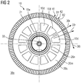
- FIG. 1 shown rotor 10 (rotor) of an electric machine comprises a plurality of laminated cores 21, 22, which are lined up on a common axis of symmetry 30.
- the common axis of symmetry 30 coincides with the axis of rotation 30 of the rotor 10.
- Each laminated core 21, 22 has on its lateral surface 20m (its outer circumference) a plurality of teeth 81, 82.
- the recesses 41, 42 (spaces) between the teeth 81, 82 are designed to insert or insert electrical conductors 51, 52 (made of copper, for example) there (see FIG FIGS. 3 to 6 ).
- the conductors 51, 52 are in the FIG. 1 and 2 not shown.
- Each laminated core 21, 22 is fastened by means of a hub 20n on a shaft 10w of the rotor 10. At least part of the laminated cores 21, 22 has openings 10d for guiding a coolant 10k between the hub 20n of each laminated core 21, 22 and its teeth 81, 82. Adjacent laminations 21, 22 are arranged on the common axis of symmetry 30 spaced from each other.
- the coolant 10k which is passed on at one or both end faces 10s of the rotor 10 through the apertures 10d of laminated core 21 to laminated core 22, can be in disc-shaped spaces 10z (which were initially referred to as 'radial cooling gaps') between each adjacent laminated cores 21, Distribute 22.
- the coolant 10k is conveyed within the disk-shaped intermediate spaces 10z between adjacent laminated cores 21, 22 in the radial direction 30r.
- the coolant 10k can then be returned to a coolant circuit via a coolant outflow (not shown in the figures) in the stator, not shown, of the electric machine. In an open system, this is done by venting the coolant into the environment (for example, when ambient air is used as the coolant).
- FIG. 2 shows a section along a transverse plane 10e of the rotor 10 of FIG. 1 ,
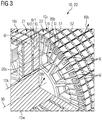
- FIG. 3 shows a partial view of a rotor 10 with electrical conductors 51, 52, respectively FIG. 1 According to the state of the art.
- On at least one end face 20s of at least one of the laminated cores 21, 22 is centered to the side surface 80z of each tooth 81, 82 of the laminated core 21, 22 a web 6i attached.
- the web 6i may be welded, soldered or plugged into the laminated core 21, 22 on the laminated core 21, 22, for example.
- the reference numeral 6L denotes a tab of a web 6i, which is inserted into a laminated core 21 in order to store the web 6i in a form-fitting manner.
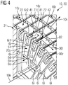
- FIG. 4 shows a detailed view of FIG. 3 ,
- Each land 6i has a longitudinal axis 6a, a width direction 6b, a thickness direction 6d and an end direction 6e.
- an extension of the web 6i in the direction of the longitudinal axis 6a is greater than in the width direction 6b and an extension of the web 6i in the width direction 6b greater than in the thickness direction 6d.
- a first distance 71 between the web 6i and a first recess 41 for a first electrical conductor 51 is the same size as a second distance 72 between the web 6i and a second recess 42 for a second electrical conductor 52, the to first recess 41 is adjacent.
- FIG. 5 shows a detail view of the view of FIG. 2
- a first distance 71 between the web 6i and a first recess 41 for a first electrical conductor 51 is smaller than a second distance 72 between the web 6i and a second recess 42nd for a second electrical conductor 52 which is adjacent to the first recess 41.
- the longitudinal axis 6a of each web 6i extends radially to the common axis of symmetry 30th
- FIG. 6 shows a detail view of the view of FIG. 2 for a second embodiment of the rotor 10 with electrical conductors 51, 52.
- a first distance 71 between the web 6i and a first recess 41 for a first electrical conductor 51 is smaller than a second distance 72 between the web 6i and a second recess 42 for a second electrical conductor 52 which is adjacent to the first recess 41.
- the longitudinal axis 6a of each web 6i does not extend radially to the common axis of symmetry 30, so that the longitudinal axis 6a has no point of intersection with the common axis of symmetry 30.
- FIG. 7 shows a detail view of the view of FIG. 2 for a third embodiment of the rotor 10 with electrical conductors 51, 52.
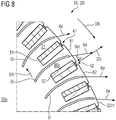
- the Webs 6i formed scoop-shaped.
- a projection or a section of the web 6i on a transverse plane 30e of the common axis of symmetry 30 has a curved course.
- the web 6i ends in the region of the lateral surface 20m of the laminated core 21 in the radial direction 30r.
- a first distance 71 between an end region of the web 6i and a first recess 41 for a first electrical conductor 51 is smaller than a second distance 72 between the web 6i and a second recess 42 for a second electrical conductor 52 which is adjacent to the first recess 41.
- FIG. 8 shows a detail view of the view of FIG. 2 for a fourth embodiment of the rotor 10 with electrical conductors 51, 52. Also in the embodiment of FIG. 8 the webs 6i are formed scoop-shaped. As a result, a projection or a section of the web 6i on a transverse plane 30e of the common axis of symmetry 30 has a curved course. In the fourth exemplary embodiment, the web 6i ends in the region of the lateral surface 20m of the laminated core 21 in an end direction 6e, which, relative to the common axis of symmetry 30, has a tangential component 6et.
- the rotor 10 can be given a modified radial fan function. With these measures, even a coolant pump or a coolant fan may even be dispensed with with low cooling power requirements.
- a particularly advantageous embodiment provides that the web 6i has a first edge side 6r1 and a second edge side 6r2, wherein the first edge side 6r1 contacts a first laminated core 21 and the second edge side 6r2 contacts a second laminated core 22.
- a laminated core assembly 20 for an electromagnetic device comprising at least two ring or ring segment-shaped laminated cores 21, 22, which are arranged side by side on a common axis of symmetry 30 lined up parallel to each other. At least two of the laminated cores 21, 22 are adjacent and spaced apart.
- the laminated cores 21, 22 each have at least one first and one second recess 41, 42.
- the recesses 41, 42 are each provided for receiving at least one electrical conductor 51, 52.
- the laminated core arrangement comprises at least one web 6i whose width direction 6b extends predominantly parallel to the common axis of symmetry 30 and whose thickness direction 6d, with respect to the common axis of symmetry 30, extends predominantly in the tangential direction 30t.
- the web 6i is arranged asymmetrically with respect to the tangential direction 30t between two adjacent recesses 41, 42.
Landscapes
- Engineering & Computer Science (AREA)
- Power Engineering (AREA)
- Iron Core Of Rotating Electric Machines (AREA)
- Coils Or Transformers For Communication (AREA)
Description
- Die Erfindung betrifft einen Rotor nach dem Oberbegriff des Anspruchs 1. Ein solcher Rotor weist eine Blechpaketanordnung für eine elektromagnetische Vorrichtung, und zwar den Rotor, auf. Die Blechpaketanordnung umfasst mindestens zwei ring- oder ringsegmentförmige Blechpakete und mindestens einen Steg, dessen Breitenrichtung überwiegend parallel zur gemeinsamen Symmetrieachse verläuft und dessen Dickenrichtung bezogen auf die gemeinsame Symmetrieachse überwiegend in Tangentialrichtung verläuft. Die Blechpakete sind auf einer gemeinsamen Symmetrieachse nebeneinander flächenparallel aufgereiht angeordnet. Mindestens zwei der Blechpakete sind benachbart und zueinander beabstandet angeordnet. Die Blechpakete weisen jeweils mindestens eine erste und eine zweite Aussparung auf, die jeweils zur Aufnahme mindestens eines elektrischen Leiters vorgesehen sind. Typischerweise ist der elektrische Leiter mit seiner Längsachse überwiegend parallel zur gemeinsamen Symmetrieachse angeordnet, wenn er in die Aussparungen aufgenommen ist.
- Es gibt elektrische Maschinen die axiale und radiale Kühlspalte zur Zuführung eines Kühlmittels aufweisen. Das Kühlmittel kann beispielsweise ein Kühlgas, eine Kühlflüssigkeit und/oder ein (anderes) Fluid zum Kühlen sein. Das Kühlmittel (beispielsweise Luft) wird mittels eines Lüfters oder einer Pumpe in die axialen Kühlspalte gedrückt, von wo aus es in die radialen Kühlspalte gepresst wird. In den radialen Kühlspalten sind blättchenförmige Stege angeordnet, um benachbarte Blechpakete auf Abstand zu halten und/oder um den Kühlmittelstrom in der Kühlspalte zu führen. Die Stege werden mittels einer Klebeverbindung, mittels einer Schweißverbindung oder mittels eines Formschlusses an mindestens einem der beiden Blechpakete befestigt.
- Weiterhin offenbart die
DE 20 2011 107 009 U1 einen Abstandshalter für ein Blechpaket einer elektrischen Maschine. Ferner offenbart dieUS 2003/00771525 A1 US 4 362 960 offenbart eine Abstandsanordnung für eine Statorbelüftungsleitung einer elektrischen Leistungsmaschine. Schließlich offenbart dieDE 10 2008 016 758 A1 einen Stator für eine elektrische Maschine sowie eine elektrische Maschine mit einem solchen Stator. - Der Erfindung liegt die Aufgabe zugrunde, einen Wirkungsgrad des Kühlsystems zu verbessern. Die Verbesserung des Wirkungsgrads kann beispielsweise in einer Verbesserung einer Kühlleistung und/oder in einer Verringerung eines Leistungsbedarfs und/oder einer Verringerung einer Leistungsanforderung an einen Kühlmittellüfter oder an eine Kühlmittelpumpe bestehen. Darüber hinaus ist es eine Aufgabe der Erfindung, ein entsprechendes Verfahren mit diesem Vorteil bereitzustellen.
- Erfindungsgemäß wird die Aufgabe durch einen Rotor nach Anspruch 1. Insbesondere umfasst der Rotor mindestens zwei ring- oder ringsegmentförmige Blechpakete und mindestens einen Steg, dessen Breitenrichtung überwiegend parallel zu einer gemeinsamen Symmetrieachse verläuft und dessen Dickenrichtung bezogen auf die gemeinsame Symmetrieachse überwiegend in Tangentialrichtung verläuft. Die ring- oder ringsegmentförmigen Blechpakete sind auf der gemeinsamen Symmetrieachse nebeneinander flächenparallel aufgereiht angeordnet. Mindestens zwei der Blechpakete sind benachbart und zueinander beabstandet angeordnet. Die Blechpakete weisen jeweils mindestens eine erste und eine zweite Aussparung auf. Die Aussparungen sind jeweils zur Aufnahme mindestens eines elektrischen Leiters vorgesehen. Der Steg ist bezogen auf die Tangentialrichtung zwischen zwei benachbarten Aussparungen unsymmetrisch angeordnet.
- Ein Konzept der vorliegenden Erfindung kann darin gesehen werden, dass die Stege für eine bevorzugte Anströmrichtung und/oder Drehrichtung der elektromagnetischen Vorrichtung strömungsoptimiert angeordnet werden, um unerwünschte Strömungswiderstände zu verringern, einen Durchsatz des Kühlmittels durch die elektromagnetische Vorrichtung zu erhöhen und/oder eine Kühlmittelzufuhr für zu kühlende Teile der elektromagnetischen Vorrichtung zu verbessern.
- Bevorzugt ist, wenn ein erster Abstand des Stegs zu der ersten Aussparung kleiner ist als ein zweiter Abstand des Stegs zu der zweiten Aussparung. Hierdurch wird in einer Drehrichtung des Rotors ein Durchsatz des Kühlmittels durch radiale Kühlspalte zwischen benachbarten Blechpaketen erhöht und somit eine Kühlleistung verbessert.
- Eine Weiterbildung sieht vor, dass eine Längsachse des Stegs die gemeinsame Symmetrieachse schneidet. Hierdurch wird vermieden, dass sich durch die unsymmetrische Anordnung des Stegs zwischen den benachbarten Aussparungen eine Länge des Stegs erhöht. Somit wird für die Stege nur ein Minimum an Material benötigt, um einen Radiusbereich mittels Distanzstegen zu versteifen. Hierdurch wird erreicht, dass sich durch die unsymmetrische Anordnung des Stegs ein Trägheitsmoment der elektromagnetischen Vorrichtung nicht erhöht.
- Eine alternative Weiterbildung sieht vor, dass eine Längsachse des Stegs die gemeinsame Symmetrieachse nicht schneidet. Dies ist eine weitere Maßnahme, um in einer Drehrichtung des Rotors einen Durchsatz des Kühlmittels durch die scheibenförmigen Zwischenräume zwischen benachbarten Blechpaketen zu erhöhen und somit eine Kühlleistung verbessern.
- Es ist auch zweckmäßig, wenn eine Projektion oder ein Schnitt des Stegs auf eine Transversalebene der gemeinsamen Symmetrieachse einen gekrümmten Verlauf aufweist. Hierdurch kann die Kühlmittelströmung strömungstechnisch optimiert werden, um das Kühlmittel mit möglichst geringem Strömungswiderstand (somit mit möglichst geringen mechanischen Energieverlusten) zu Orten zu befördern, die vorrangig zu kühlen sind.
- Es kann auch von Vorteil sein, wenn der Steg an einer Mantelfläche des Blechpakets bezogen auf die gemeinsame Symmetrieachse in Radialrichtung endet. Hierdurch können auf das Kühlmittel wirkende Fliehkräfte bestmöglich genutzt werden, um das Kühlmittel mit möglichst hoher Geschwindigkeit aus dem Rotor in Richtung Ständer zu befördern.
- Auch ist es möglich, dass der Steg an einer Mantelfläche des Blechpakets in einer Endrichtung endet, die bezogen auf die gemeinsame Symmetrieachse eine Tangentialkomponente aufweist. Hierdurch können auf das Kühlmittel wirkende Fliehkräfte bestmöglich genutzt werden, um das Kühlmittel mit möglichst hoher Geschwindigkeit aus dem Rotor in Richtung eines Spalts zu befördern, der sich zwischen Ständer und Läufer befindet.
- Eine weitere Möglichkeit besteht darin, dass der Steg als Schaufel ausgebildet ist, die bezogen auf die gemeinsame Symmetrieachse im Verlauf über eine Radialrichtung und/oder im Verlauf über eine Richtung parallel zur gemeinsamen Symmetrieachse in der Tangentialrichtung gekrümmt ist. Durch eine schaufelförmige oder konkave Ausbildung des Steges kann ein Strömungsprofil des Kühlmittelflusses über die Tangentialrichtung und/oder über eine Richtung parallel zur gemeinsamen Symmetrieachse optimiert werden. Die Richtung, welche parallel zur gemeinsamen Symmetrieachse verläuft, kann auch als Axialrichtung bezeichnet werden.
- Die elektromagnetische Vorrichtung kann beispielsweise ein Rotor und/oder ein Stator einer elektrischen Maschine sein. Alternativ kann sie beispielsweise ein Transformator oder ein Elektromagnet sein. Hierdurch ist es möglich, die Erfindung für eine Verbesserung einer Vielzahl von unterschiedlichen elektromagnetischen Vorrichtungen zu nutzen.
- Die Erfindung ist anhand der beigefügten Zeichnungen näher erläutert, in denen zeigen:
- FIG 1
- schematisch einen Rotor (eines Käfigläufers ohne elektrische Leiter) einer elektrischen Maschine in einer perspektivischen Ansicht;
- FIG 2
- schematisch einen Schnitt entlang einer Transversalebene des Rotors der
FIG 1 ; - FIG 3
- schematisch eine perspektivische Teilansicht des Rotors der
FIG 1 (mit elektrischen Leitern) mit einem abgewinkelten Schnittverlauf (Stand der Technik); - FIG 4
- schematisch eine perspektivische Detailansicht der
FIG 3 ; - FIG 5
- schematisch eine Detailansicht der Ansicht der
FIG 2 für eine erste Ausführungsform des Rotors der vorliegenden Erfindung mit elektrischen Leitern; - FIG 6
- schematisch eine Detailansicht der Ansicht der
FIG 2 für eine zweite Ausführungsform des Rotors der vorliegenden Erfindung mit elektrischen Leitern; - FIG 7
- schematisch eine Detailansicht der Ansicht der
FIG 2 für eine dritte Ausführungsform des Rotors der vorliegenden Erfindung mit elektrischen Leitern; - FIG 8
- schematisch eine Detailansicht der Ansicht der
FIG 2 für eine vierte Ausführungsform des Rotors der vorliegenden Erfindung mit elektrischen Leitern. - Die nachfolgend näher geschilderten Ausführungsbeispiele stellen bevorzugte Ausführungsformen der vorliegenden Erfindung dar.
- Der in
FIG 1 gezeigte Rotor 10 (Läufer) einer elektrischen Maschine umfasst mehrere Blechpakete 21, 22, die auf einer gemeinsamen Symmetrieachse 30 aufgereiht sind. Die gemeinsame Symmetrieachse 30 stimmt mit der Rotationsachse 30 des Rotors 10 überein. Jedes Blechpaket 21, 22 weist an seiner Mantelfläche 20m (seinem Außenumfang) eine Vielzahl von Zähnen 81, 82 auf. Die Aussparungen 41, 42 (Zwischenräume) zwischen den Zähnen 81, 82 sind dafür vorgesehen, dort elektrische Leiter 51, 52 (die beispielsweise aus Kupfer bestehen) einzulegen oder einzuschieben (sieheFIG 3 bis 6 ). Die Leiter 51, 52 sind in denFIG 1 und2 nicht dargestellt. Jedes Blechpaket 21, 22 ist mittels einer Nabe 20n auf einer Welle 10w des Rotors 10 befestigt. Zumindest ein Teil der Blechpakete 21, 22 weist zwischen der Nabe 20n eines jeden Blechpakets 21, 22 und seinen Zähnen 81, 82 Durchbrüche 10d zur Führung eines Kühlmittels 10k auf. Benachbarte Blechpakete 21, 22 sind auf der gemeinsamen Symmetrieachse 30 zueinander beabstandet angeordnet. Das Kühlmittel 10k, das an einer oder beiden Stirnseiten 10s des Rotors 10 über die Durchbrüche 10d von Blechpaket 21 zu Blechpaket 22 weitergereicht wird, kann sich in scheibenförmigen Zwischenräumen 10z (die eingangs als 'radiale Kühlspalte' bezeichnet wurden) zwischen jeweils benachbarten Blechpaketen 21, 22 verteilen. Durch Fliehkräfte unterstützt wird das Kühlmittel 10k innerhalb der scheibenförmigen Zwischenräume 10z zwischen benachbarten Blechpaketen 21, 22 in Radialrichtung 30r befördert. Das Kühlmittel 10k kann dann über einen (in den Figuren nicht dargestellten) Kühlmittelabfluss im nicht dargestellten Ständer der elektrischen Maschine in einen Kühlmittelkreislauf zurückgeführt werden. Bei einem offenen System erfolgt dies über ein Entlassen des Kühlmittels in die Umgebung (beispielsweise, wenn als Kühlmittel Umgebungsluft verwendet wird). - Die
FIG 2 zeigt einen Schnitt entlang einer Transversalebene 10e des Rotors 10 derFIG 1 . - Die
FIG 3 zeigt eine Teilansicht eines Rotors 10 mit elektrischen Leitern 51, 52, entsprechendFIG 1 nach dem Stand der Technik. Auf mindestens einer Stirnseite 20s mindestens eines der Blechpakete 21, 22 ist mittig zur Seitenfläche 80z eines jeden Zahns 81, 82 des Blechpakets 21, 22 ein Steg 6i befestigt. Der Steg 6i kann an dem Blechpaket 21, 22 beispielsweise angeschweißt, angelötet oder in das Blechpaket 21, 22 eingesteckt sein. Das Bezugszeichen 6L bezeichnet eine Lasche eines Stegs 6i, die in ein Blechpaket 21 eingesteckt ist, um den Steg 6i darin formschlüssig zu lagern. - Die
FIG 4 zeigt eine Detailansicht derFIG 3 . Jeder Steg 6i hat eine Längsachse 6a, eine Breitenrichtung 6b, eine Dickenrichtung 6d und eine Endrichtung 6e. Typischerweise ist eine Ausdehnung des Stegs 6i in Richtung der Längsachse 6a größer als in Breitenrichtung 6b und eine Ausdehnung des Stegs 6i in Breitenrichtung 6b größer als in Dickenrichtung 6d. Bei herkömmlichen elektrischen Maschinen ist ein erster Abstand 71 zwischen dem Steg 6i und einer ersten Aussparung 41 für einen ersten elektrischen Leiter 51 gleich groß wie ein zweiter Abstand 72 zwischen dem Steg 6i und einer zweiten Aussparung 42 für einen zweiten elektrischen Leiter 52, die zu der ersten Aussparung 41 benachbart ist. - Die
FIG 5 zeigt eine Detailansicht der Ansicht derFIG 2 für eine erste Ausführungsform des Rotors 10 mit elektrischen Leitern 51, 52. Hierbei ist ein erster Abstand 71 zwischen dem Steg 6i und einer ersten Aussparung 41 für einen ersten elektrischen Leiter 51 kleiner als ein zweiter Abstand 72 zwischen dem Steg 6i und einer zweiten Aussparung 42 für einen zweiten elektrischen Leiter 52, die zu der ersten Aussparung 41 benachbart ist. In dem Ausführungsbeispiel derFIG 5 verläuft die Längsachse 6a eines jeden Stegs 6i radial zur gemeinsamen Symmetrieachse 30. - Die
FIG 6 zeigt eine Detailansicht der Ansicht derFIG 2 für eine zweite Ausführungsform des Rotors 10 mit elektrischen Leitern 51, 52. Auch hier ist ein erster Abstand 71 zwischen dem Steg 6i und einer ersten Aussparung 41 für einen ersten elektrischen Leiter 51 kleiner als ein zweiter Abstand 72 zwischen dem Steg 6i und einer zweiten Aussparung 42 für einen zweiten elektrischen Leiter 52, die zu der ersten Aussparung 41 benachbart ist. In dem Ausführungsbeispiel derFIG 6 verläuft die Längsachse 6a eines jeden Stegs 6i nicht radial zu der gemeinsamen Symmetrieachse 30, so dass die Längsachse 6a keinen Schnittpunkt mit der gemeinsamen Symmetrieachse 30 hat. - Die
FIG 7 zeigt eine Detailansicht der Ansicht derFIG 2 für eine dritte Ausführungsform des Rotors 10 mit elektrischen Leitern 51, 52. In dem Ausführungsbeispiel derFIG 7 sind die Stege 6i schaufelförmig ausgebildet. Dadurch weist eine Projektion oder ein Schnitt des Stegs 6i auf eine Transversalebene 30e der gemeinsamen Symmetrieachse 30 einen gekrümmten Verlauf auf. In dem dritten Ausführungsbeispiel endet der Steg 6i im Bereich der Mantelfläche 20m des Blechpakets 21 in Radialrichtung 30r. - In dem Ausführungsbeispiel der
FIG 7 ist eine optionale Variante der dritten Ausführungsform gezeigt, in welcher ein erster Abstand 71 zwischen einem Endbereich des Stegs 6i und einer ersten Aussparung 41 für einen ersten elektrischen Leiter 51 kleiner ist als ein zweiter Abstand 72 zwischen dem Steg 6i und einer zweiten Aussparung 42 für einen zweiten elektrischen Leiter 52, die zu der ersten Aussparung 41 benachbart ist. - Die
FIG 8 zeigt eine Detailansicht der Ansicht derFIG 2 für eine vierte Ausführungsform des Rotors 10 mit elektrischen Leitern 51, 52. Auch in dem Ausführungsbeispiel derFIG 8 sind die Stege 6i schaufelförmig ausgebildet. Dadurch weist eine Projektion oder ein Schnitt des Stegs 6i auf eine Transversalebene 30e der gemeinsamen Symmetrieachse 30 einen gekrümmten Verlauf auf. In dem vierten Ausführungsbeispiel endet der Steg 6i im Bereich der Mantelfläche 20m des Blechpakets 21 in einer Endrichtung 6e, die bezogen auf die gemeinsame Symmetrieachse 30 eine Tangentialkomponente 6et aufweist. - Mittels der unsymmetrischen Anordnung des oder der Stege 6i und/oder mittels einer schaufelförmigen Form des oder der Stege 6i kann dem Rotor 10 eine geänderte Radiallüfterfunktion verliehen werden. Durch diese Maßnahmen kann bei geringen Kühlleistungsanforderungen unter Umständen sogar auf eine Kühlmittelpumpe oder auf ein Kühlmittelgebläse verzichtet werden.
- Alle in der Figurenbeschreibung beschriebenen Ausführungsformen haben gemeinsam, dass es für die elektromagnetische Vorrichtung eine bevorzugte Anströmrichtung SR gibt und/oder dass es für den Rotor 10r eine bevorzugte Drehrichtung DR gibt, in der (gegenüber einer entgegengesetzten Anströmrichtung und/oder einer entgegengesetzten Drehrichtung) unerwünschte Strömungswiderstände verringert sind, ein Durchsatz des Kühlmittels durch die elektromagnetische Vorrichtung erhöht ist und/oder eine Kühlmittelzufuhr für zu kühlende Teile der elektromagnetischen Vorrichtung verbessert ist.
- Eine besonders vorteilhafte Ausführungsform sieht vor, dass der Steg 6i eine erste Randseite 6r1 und eine zweite Randseite 6r2 aufweist, wobei die erste Randseite 6r1 ein erstes Blechpaket 21 berührt und die zweite Randseite 6r2 ein zweites Blechpaket 22 berührt.
- Es wird eine Blechpaketanordnung 20 für eine elektromagnetische Vorrichtung vorgeschlagen, die mindestens zwei ring- oder ringsegmentförmige Blechpakete 21, 22 umfasst, die auf einer gemeinsamen Symmetrieachse 30 nebeneinander flächenparallel aufgereiht angeordnet sind. Mindestens zwei der Blechpakete 21, 22 sind benachbart und zueinander beabstandet. Die Blechpakete 21, 22 weisen jeweils mindestens eine erste und eine zweite Aussparung 41, 42 auf. Die Aussparungen 41, 42 sind jeweils zur Aufnahme mindestens eines elektrischen Leiters 51, 52 vorgesehen. Die Blechpaketanordnung umfasst mindestens einen Steg 6i, dessen Breitenrichtung 6b überwiegend parallel zur gemeinsamen Symmetrieachse 30 verläuft und dessen Dickenrichtung 6d bezogen auf die gemeinsame Symmetrieachse 30 überwiegend in Tangentialrichtung 30t verläuft. Der Steg 6i ist bezogen auf die Tangentialrichtung 30t zwischen zwei benachbarten Aussparungen 41, 42 unsymmetrisch angeordnet.
Claims (8)
- Rotor (10) mit einer Blechpaketanordnung (20), wobei die Blechpaketanordnung (20) umfasst:- mindestens zwei ring- oder ringsegmentförmige Blechpakete (21,22), die auf einer gemeinsamen Symmetrieachse (30) nebeneinander flächenparallel aufgereiht angeordnet sind, wobei mindestens zwei der Blechpakete (21,22) benachbart und zueinander beabstandet sind, wobei jedes Blechpaket (21,22) an seinem Außenumfang eine Vielzahl von Zähnen (81,82) aufweist, wobei die Blechpakete (21,22) zwischen den Zähnen (81,82) jeweils mindestens eine erste und eine zweite Aussparung (41,42) aufweisen, wobei die Aussparungen (41,42) jeweils zur Aufnahme mindestens eines elektrischen Leiters (51,52) vorgesehen sind, wobei jedes der Blechpakete (21,22) mittels einer Nabe (20n) auf einer Welle (10w) des Rotors (10) befestigt ist, dessen Rotationsachse mit der gemeinsamen Symmetrieachse (30) zusammenfällt, und wobei jedes der Blechpakete (21,22) zwischen der Nabe (20n) eines jeden Blechpakets (21,22) und seinen Zähnen (81,82) Durchbrüche (10d) zur Führung eines Kühlmittels (10k) aufweist;- mindestens ein Steg (6i), dessen Breitenrichtung (6b) überwiegend parallel zur gemeinsamen Symmetrieachse (30) verläuft und dessen Dickenrichtung (6d) bezogen auf die gemeinsame Symmetrieachse (30) überwiegend in Tangentialrichtung (30t) verläuft;dadurch gekennzeichnet, dass
der Steg (6i) bezogen auf die Tangentialrichtung (30t) zwischen zwei benachbarten Aussparungen (41,42) unsymmetrisch angeordnet ist und sich radial höchstens bis zu den Durchbrüchen (10d) erstreckt. - Rotor (10) nach Anspruch 1, dadurch gekennzeichnet, dass ein erster Abstand (71) des Stegs (6i) zu der ersten Aussparung (41) kleiner ist als ein zweiter Abstand (72) des Stegs (6i) zu der zweiten Aussparung (72).
- Rotor (10) nach Anspruch 1 oder 2, dadurch gekennzeichnet, dass eine Längsachse (6a) des Stegs (6i) die gemeinsame Symmetrieachse (30) schneidet.
- Rotor (10) nach Anspruch 1 oder 2, dadurch gekennzeichnet, dass eine Längsachse (6a) des Stegs (6i) die gemeinsame Symmetrieachse (30) nicht schneidet.
- Rotor (10) nach einem der Ansprüche 1 bis 4, dadurch gekennzeichnet, dass eine Projektion oder ein Schnitt des Stegs (6i) auf eine Transversalebene (30e) der gemeinsamen Symmetrieachse (30) einen gekrümmten Verlauf aufweist.
- Rotor (10) nach Anspruch 5, dadurch gekennzeichnet, dass der Steg (6i) an einer Mantelfläche (20m) des Blechpakets (21,22) bezogen auf die gemeinsame Symmetrieachse (30) in Radialrichtung (30r) endet.
- Rotor (10) nach Anspruch 5, dadurch gekennzeichnet, dass der Steg (6i) an einer Mantelfläche (20m) des Blechpakets (21,22) in einer Endrichtung (6e) endet, die bezogen auf die gemeinsame Symmetrieachse (30) eine Tangentialkomponente (6et) aufweist.
- Rotor (10) nach einem der Ansprüche 1 bis 7, dadurch gekennzeichnet, dass der Steg (6i) als Schaufel ausgebildet ist, die bezogen auf die gemeinsame Symmetrieachse (30) im Verlauf über eine Radialrichtung (30r) und/oder im Verlauf über eine Richtung parallel zur gemeinsamen Symmetrieachse (30) in der Tangentialrichtung (30t) gekrümmt ist.
Applications Claiming Priority (1)
| Application Number | Priority Date | Filing Date | Title |
|---|---|---|---|
| DE102013213406.1A DE102013213406A1 (de) | 2013-07-09 | 2013-07-09 | Blechpaketanordnung und elektromagnetische Vorrichtung |
Publications (3)
| Publication Number | Publication Date |
|---|---|
| EP2835889A2 EP2835889A2 (de) | 2015-02-11 |
| EP2835889A3 EP2835889A3 (de) | 2015-12-09 |
| EP2835889B1 true EP2835889B1 (de) | 2018-02-14 |
Family
ID=51059280
Family Applications (1)
| Application Number | Title | Priority Date | Filing Date |
|---|---|---|---|
| EP14173423.6A Not-in-force EP2835889B1 (de) | 2013-07-09 | 2014-06-23 | Blechpaketanordnung eines rotors |
Country Status (2)
| Country | Link |
|---|---|
| EP (1) | EP2835889B1 (de) |
| DE (1) | DE102013213406A1 (de) |
Cited By (2)
| Publication number | Priority date | Publication date | Assignee | Title |
|---|---|---|---|---|
| WO2022266809A1 (en) | 2021-06-21 | 2022-12-29 | Abb Schweiz Ag | Air duct assembly for rotor, associated rotor and electric machine |
| EP4683172A1 (de) * | 2024-07-16 | 2026-01-21 | Flender GmbH | Druckfinger für blechpaket |
Citations (1)
| Publication number | Priority date | Publication date | Assignee | Title |
|---|---|---|---|---|
| DE202011107009U1 (de) * | 2011-10-20 | 2011-11-29 | Klimtex Gmbh | Abstandshalter für Blechpaket einer elektrischen Maschine |
Family Cites Families (3)
| Publication number | Priority date | Publication date | Assignee | Title |
|---|---|---|---|---|
| FR2481853A1 (fr) * | 1980-04-30 | 1981-11-06 | Alsthom Atlantique | Distanceur d'event statorique pour machine dynamoelectrique de puissance |
| US6777836B2 (en) * | 2000-12-20 | 2004-08-17 | General Electric Company | Heat transfer enhancement at generator stator core space blocks |
| DE102008016758A1 (de) * | 2008-03-31 | 2009-10-01 | Alstom Technology Ltd. | Stator für eine elektrische Maschine sowie elektrische Maschine mit einem solchen Stator |
-
2013
- 2013-07-09 DE DE102013213406.1A patent/DE102013213406A1/de not_active Withdrawn
-
2014
- 2014-06-23 EP EP14173423.6A patent/EP2835889B1/de not_active Not-in-force
Patent Citations (1)
| Publication number | Priority date | Publication date | Assignee | Title |
|---|---|---|---|---|
| DE202011107009U1 (de) * | 2011-10-20 | 2011-11-29 | Klimtex Gmbh | Abstandshalter für Blechpaket einer elektrischen Maschine |
Cited By (4)
| Publication number | Priority date | Publication date | Assignee | Title |
|---|---|---|---|---|
| WO2022266809A1 (en) | 2021-06-21 | 2022-12-29 | Abb Schweiz Ag | Air duct assembly for rotor, associated rotor and electric machine |
| EP4360196A4 (de) * | 2021-06-21 | 2025-03-05 | Abb Schweiz Ag | Luftkanalanordnung für rotor, zugehöriger rotor und elektrische maschine |
| EP4683172A1 (de) * | 2024-07-16 | 2026-01-21 | Flender GmbH | Druckfinger für blechpaket |
| WO2026017414A1 (de) | 2024-07-16 | 2026-01-22 | Flender Gmbh | Druckfinger für blechpaket |
Also Published As
| Publication number | Publication date |
|---|---|
| EP2835889A3 (de) | 2015-12-09 |
| EP2835889A2 (de) | 2015-02-11 |
| DE102013213406A1 (de) | 2015-01-15 |
Similar Documents
| Publication | Publication Date | Title |
|---|---|---|
| DE102016210211B4 (de) | Rotor von rotierender elektrischer maschine | |
| DE102016211872B4 (de) | Rotor von rotierender elektrischer Maschine | |
| DE102008064495B3 (de) | Elektrische Maschine mit mehreren Kühlströmen und Kühlverfahren | |
| DE102016210930B4 (de) | Elektrische Maschine | |
| WO2017121526A1 (de) | Elektrische maschine | |
| DE112018004102T5 (de) | Elektrisches Antriebsmodul mit einem Motor mit einem Kühlkörpereinsatz in einer Rotorwelle | |
| DE10317593A1 (de) | Elektrische Maschine mit gekühlten Ständer- und Läuferblechpaketen und Wicklungen | |
| DE102014018223A1 (de) | Elektrische Maschine, insbesondere Asynchronmaschine | |
| WO2019072489A1 (de) | Rotorhohlwelle mit integriertem pumpenelement | |
| DE102021111700A1 (de) | Wickelkopfkühlung | |
| DE3434081A1 (de) | Umlaufende elektrische maschine | |
| DE102019217510A1 (de) | Rotor, Elektromaschine und Kraftfahrzeug | |
| WO2020239816A1 (de) | Stator mit flüssigkeitsgekühlten statorkern | |
| DE112020000996T5 (de) | Elektrische Maschine Mit Internen Kühldurchgängen | |
| EP3977597A1 (de) | Elektrische maschine | |
| EP3205004B1 (de) | Käfigläufer für eine elektrische asynchronmaschine mit einen kurzschlussring stabilisierender stützscheibe | |
| WO2016005082A1 (de) | Strömungsgekühlte elektrische maschine mit einem scheibenläufer | |
| EP2835889A2 (de) | Blechpaketanordnung und elektromagnetische Vorrichtung | |
| DE102016008686A1 (de) | Kernkörper für Statoren und/oder Rotoren von elektrischen Maschinen, Stator/Rotor mit einem solchen Kernkörper sowie elektrische Maschine mit einem solchen Kernkörper | |
| WO2005099070A1 (de) | Kühlvorrichtung für eine mit einer kühlflüssigkeit kühlbaren elektrischen maschine | |
| DE102008016758A1 (de) | Stator für eine elektrische Maschine sowie elektrische Maschine mit einem solchen Stator | |
| EP3657635A1 (de) | Rotor für eine asynchronmaschine mit verlustoptimierter stabgeometrie, asynchronmaschine sowie verfahren | |
| DE102023201952A1 (de) | Elektrische Maschine für ein Kraftfahrzeug | |
| DE69932309T2 (de) | Zwangskonvektions-Kühlangordnung für rotierende elektrische Maschinen | |
| EP2693608A1 (de) | Wicklung für eine elektrische Maschine |
Legal Events
| Date | Code | Title | Description |
|---|---|---|---|
| PUAI | Public reference made under article 153(3) epc to a published international application that has entered the european phase |
Free format text: ORIGINAL CODE: 0009012 |
|
| 17P | Request for examination filed |
Effective date: 20140623 |
|
| AK | Designated contracting states |
Kind code of ref document: A2 Designated state(s): AL AT BE BG CH CY CZ DE DK EE ES FI FR GB GR HR HU IE IS IT LI LT LU LV MC MK MT NL NO PL PT RO RS SE SI SK SM TR |
|
| AX | Request for extension of the european patent |
Extension state: BA ME |
|
| PUAL | Search report despatched |
Free format text: ORIGINAL CODE: 0009013 |
|
| AK | Designated contracting states |
Kind code of ref document: A3 Designated state(s): AL AT BE BG CH CY CZ DE DK EE ES FI FR GB GR HR HU IE IS IT LI LT LU LV MC MK MT NL NO PL PT RO RS SE SI SK SM TR |
|
| AX | Request for extension of the european patent |
Extension state: BA ME |
|
| RIC1 | Information provided on ipc code assigned before grant |
Ipc: H02K 1/32 20060101AFI20151030BHEP Ipc: H02K 1/26 20060101ALI20151030BHEP |
|
| R17P | Request for examination filed (corrected) |
Effective date: 20160606 |
|
| RBV | Designated contracting states (corrected) |
Designated state(s): AL AT BE BG CH CY CZ DE DK EE ES FI FR GB GR HR HU IE IS IT LI LT LU LV MC MK MT NL NO PL PT RO RS SE SI SK SM TR |
|
| 17Q | First examination report despatched |
Effective date: 20161011 |
|
| RAP1 | Party data changed (applicant data changed or rights of an application transferred) |
Owner name: SIEMENS AKTIENGESELLSCHAFT |
|
| GRAP | Despatch of communication of intention to grant a patent |
Free format text: ORIGINAL CODE: EPIDOSNIGR1 |
|
| INTG | Intention to grant announced |
Effective date: 20170925 |
|
| GRAS | Grant fee paid |
Free format text: ORIGINAL CODE: EPIDOSNIGR3 |
|
| GRAA | (expected) grant |
Free format text: ORIGINAL CODE: 0009210 |
|
| AK | Designated contracting states |
Kind code of ref document: B1 Designated state(s): AL AT BE BG CH CY CZ DE DK EE ES FI FR GB GR HR HU IE IS IT LI LT LU LV MC MK MT NL NO PL PT RO RS SE SI SK SM TR |
|
| REG | Reference to a national code |
Ref country code: GB Ref legal event code: FG4D Free format text: NOT ENGLISH |
|
| REG | Reference to a national code |
Ref country code: CH Ref legal event code: EP |
|
| REG | Reference to a national code |
Ref country code: IE Ref legal event code: FG4D Free format text: LANGUAGE OF EP DOCUMENT: GERMAN |
|
| REG | Reference to a national code |
Ref country code: DE Ref legal event code: R096 Ref document number: 502014007229 Country of ref document: DE Ref country code: AT Ref legal event code: REF Ref document number: 970468 Country of ref document: AT Kind code of ref document: T Effective date: 20180315 |
|
| REG | Reference to a national code |
Ref country code: NL Ref legal event code: MP Effective date: 20180214 |
|
| PG25 | Lapsed in a contracting state [announced via postgrant information from national office to epo] |
Ref country code: CY Free format text: LAPSE BECAUSE OF FAILURE TO SUBMIT A TRANSLATION OF THE DESCRIPTION OR TO PAY THE FEE WITHIN THE PRESCRIBED TIME-LIMIT Effective date: 20180214 Ref country code: LT Free format text: LAPSE BECAUSE OF FAILURE TO SUBMIT A TRANSLATION OF THE DESCRIPTION OR TO PAY THE FEE WITHIN THE PRESCRIBED TIME-LIMIT Effective date: 20180214 Ref country code: HR Free format text: LAPSE BECAUSE OF FAILURE TO SUBMIT A TRANSLATION OF THE DESCRIPTION OR TO PAY THE FEE WITHIN THE PRESCRIBED TIME-LIMIT Effective date: 20180214 Ref country code: NO Free format text: LAPSE BECAUSE OF FAILURE TO SUBMIT A TRANSLATION OF THE DESCRIPTION OR TO PAY THE FEE WITHIN THE PRESCRIBED TIME-LIMIT Effective date: 20180514 Ref country code: FI Free format text: LAPSE BECAUSE OF FAILURE TO SUBMIT A TRANSLATION OF THE DESCRIPTION OR TO PAY THE FEE WITHIN THE PRESCRIBED TIME-LIMIT Effective date: 20180214 Ref country code: NL Free format text: LAPSE BECAUSE OF FAILURE TO SUBMIT A TRANSLATION OF THE DESCRIPTION OR TO PAY THE FEE WITHIN THE PRESCRIBED TIME-LIMIT Effective date: 20180214 Ref country code: ES Free format text: LAPSE BECAUSE OF FAILURE TO SUBMIT A TRANSLATION OF THE DESCRIPTION OR TO PAY THE FEE WITHIN THE PRESCRIBED TIME-LIMIT Effective date: 20180214 |
|
| PG25 | Lapsed in a contracting state [announced via postgrant information from national office to epo] |
Ref country code: RS Free format text: LAPSE BECAUSE OF FAILURE TO SUBMIT A TRANSLATION OF THE DESCRIPTION OR TO PAY THE FEE WITHIN THE PRESCRIBED TIME-LIMIT Effective date: 20180214 Ref country code: LV Free format text: LAPSE BECAUSE OF FAILURE TO SUBMIT A TRANSLATION OF THE DESCRIPTION OR TO PAY THE FEE WITHIN THE PRESCRIBED TIME-LIMIT Effective date: 20180214 Ref country code: SE Free format text: LAPSE BECAUSE OF FAILURE TO SUBMIT A TRANSLATION OF THE DESCRIPTION OR TO PAY THE FEE WITHIN THE PRESCRIBED TIME-LIMIT Effective date: 20180214 Ref country code: GR Free format text: LAPSE BECAUSE OF FAILURE TO SUBMIT A TRANSLATION OF THE DESCRIPTION OR TO PAY THE FEE WITHIN THE PRESCRIBED TIME-LIMIT Effective date: 20180515 Ref country code: BG Free format text: LAPSE BECAUSE OF FAILURE TO SUBMIT A TRANSLATION OF THE DESCRIPTION OR TO PAY THE FEE WITHIN THE PRESCRIBED TIME-LIMIT Effective date: 20180514 |
|
| PG25 | Lapsed in a contracting state [announced via postgrant information from national office to epo] |
Ref country code: MT Free format text: LAPSE BECAUSE OF FAILURE TO SUBMIT A TRANSLATION OF THE DESCRIPTION OR TO PAY THE FEE WITHIN THE PRESCRIBED TIME-LIMIT Effective date: 20180214 |
|
| PG25 | Lapsed in a contracting state [announced via postgrant information from national office to epo] |
Ref country code: AL Free format text: LAPSE BECAUSE OF FAILURE TO SUBMIT A TRANSLATION OF THE DESCRIPTION OR TO PAY THE FEE WITHIN THE PRESCRIBED TIME-LIMIT Effective date: 20180214 Ref country code: IT Free format text: LAPSE BECAUSE OF FAILURE TO SUBMIT A TRANSLATION OF THE DESCRIPTION OR TO PAY THE FEE WITHIN THE PRESCRIBED TIME-LIMIT Effective date: 20180214 Ref country code: EE Free format text: LAPSE BECAUSE OF FAILURE TO SUBMIT A TRANSLATION OF THE DESCRIPTION OR TO PAY THE FEE WITHIN THE PRESCRIBED TIME-LIMIT Effective date: 20180214 Ref country code: RO Free format text: LAPSE BECAUSE OF FAILURE TO SUBMIT A TRANSLATION OF THE DESCRIPTION OR TO PAY THE FEE WITHIN THE PRESCRIBED TIME-LIMIT Effective date: 20180214 Ref country code: PL Free format text: LAPSE BECAUSE OF FAILURE TO SUBMIT A TRANSLATION OF THE DESCRIPTION OR TO PAY THE FEE WITHIN THE PRESCRIBED TIME-LIMIT Effective date: 20180214 |
|
| PGFP | Annual fee paid to national office [announced via postgrant information from national office to epo] |
Ref country code: DE Payment date: 20180820 Year of fee payment: 5 |
|
| REG | Reference to a national code |
Ref country code: DE Ref legal event code: R097 Ref document number: 502014007229 Country of ref document: DE |
|
| PG25 | Lapsed in a contracting state [announced via postgrant information from national office to epo] |
Ref country code: SK Free format text: LAPSE BECAUSE OF FAILURE TO SUBMIT A TRANSLATION OF THE DESCRIPTION OR TO PAY THE FEE WITHIN THE PRESCRIBED TIME-LIMIT Effective date: 20180214 Ref country code: DK Free format text: LAPSE BECAUSE OF FAILURE TO SUBMIT A TRANSLATION OF THE DESCRIPTION OR TO PAY THE FEE WITHIN THE PRESCRIBED TIME-LIMIT Effective date: 20180214 Ref country code: SM Free format text: LAPSE BECAUSE OF FAILURE TO SUBMIT A TRANSLATION OF THE DESCRIPTION OR TO PAY THE FEE WITHIN THE PRESCRIBED TIME-LIMIT Effective date: 20180214 Ref country code: CZ Free format text: LAPSE BECAUSE OF FAILURE TO SUBMIT A TRANSLATION OF THE DESCRIPTION OR TO PAY THE FEE WITHIN THE PRESCRIBED TIME-LIMIT Effective date: 20180214 |
|
| PLBE | No opposition filed within time limit |
Free format text: ORIGINAL CODE: 0009261 |
|
| STAA | Information on the status of an ep patent application or granted ep patent |
Free format text: STATUS: NO OPPOSITION FILED WITHIN TIME LIMIT |
|
| 26N | No opposition filed |
Effective date: 20181115 |
|
| REG | Reference to a national code |
Ref country code: CH Ref legal event code: PL |
|
| GBPC | Gb: european patent ceased through non-payment of renewal fee |
Effective date: 20180623 |
|
| PG25 | Lapsed in a contracting state [announced via postgrant information from national office to epo] |
Ref country code: SI Free format text: LAPSE BECAUSE OF FAILURE TO SUBMIT A TRANSLATION OF THE DESCRIPTION OR TO PAY THE FEE WITHIN THE PRESCRIBED TIME-LIMIT Effective date: 20180214 |
|
| REG | Reference to a national code |
Ref country code: BE Ref legal event code: MM Effective date: 20180630 |
|
| REG | Reference to a national code |
Ref country code: IE Ref legal event code: MM4A |
|
| PG25 | Lapsed in a contracting state [announced via postgrant information from national office to epo] |
Ref country code: MC Free format text: LAPSE BECAUSE OF FAILURE TO SUBMIT A TRANSLATION OF THE DESCRIPTION OR TO PAY THE FEE WITHIN THE PRESCRIBED TIME-LIMIT Effective date: 20180214 Ref country code: LU Free format text: LAPSE BECAUSE OF NON-PAYMENT OF DUE FEES Effective date: 20180623 |
|
| PG25 | Lapsed in a contracting state [announced via postgrant information from national office to epo] |
Ref country code: LI Free format text: LAPSE BECAUSE OF NON-PAYMENT OF DUE FEES Effective date: 20180630 Ref country code: FR Free format text: LAPSE BECAUSE OF NON-PAYMENT OF DUE FEES Effective date: 20180630 Ref country code: GB Free format text: LAPSE BECAUSE OF NON-PAYMENT OF DUE FEES Effective date: 20180623 Ref country code: IE Free format text: LAPSE BECAUSE OF NON-PAYMENT OF DUE FEES Effective date: 20180623 Ref country code: CH Free format text: LAPSE BECAUSE OF NON-PAYMENT OF DUE FEES Effective date: 20180630 |
|
| PG25 | Lapsed in a contracting state [announced via postgrant information from national office to epo] |
Ref country code: BE Free format text: LAPSE BECAUSE OF NON-PAYMENT OF DUE FEES Effective date: 20180630 |
|
| REG | Reference to a national code |
Ref country code: DE Ref legal event code: R119 Ref document number: 502014007229 Country of ref document: DE |
|
| PG25 | Lapsed in a contracting state [announced via postgrant information from national office to epo] |
Ref country code: TR Free format text: LAPSE BECAUSE OF FAILURE TO SUBMIT A TRANSLATION OF THE DESCRIPTION OR TO PAY THE FEE WITHIN THE PRESCRIBED TIME-LIMIT Effective date: 20180214 |
|
| PG25 | Lapsed in a contracting state [announced via postgrant information from national office to epo] |
Ref country code: DE Free format text: LAPSE BECAUSE OF NON-PAYMENT OF DUE FEES Effective date: 20200101 |
|
| PG25 | Lapsed in a contracting state [announced via postgrant information from national office to epo] |
Ref country code: HU Free format text: LAPSE BECAUSE OF FAILURE TO SUBMIT A TRANSLATION OF THE DESCRIPTION OR TO PAY THE FEE WITHIN THE PRESCRIBED TIME-LIMIT; INVALID AB INITIO Effective date: 20140623 Ref country code: PT Free format text: LAPSE BECAUSE OF FAILURE TO SUBMIT A TRANSLATION OF THE DESCRIPTION OR TO PAY THE FEE WITHIN THE PRESCRIBED TIME-LIMIT Effective date: 20180214 |
|
| PG25 | Lapsed in a contracting state [announced via postgrant information from national office to epo] |
Ref country code: MK Free format text: LAPSE BECAUSE OF NON-PAYMENT OF DUE FEES Effective date: 20180214 |
|
| PG25 | Lapsed in a contracting state [announced via postgrant information from national office to epo] |
Ref country code: IS Free format text: LAPSE BECAUSE OF FAILURE TO SUBMIT A TRANSLATION OF THE DESCRIPTION OR TO PAY THE FEE WITHIN THE PRESCRIBED TIME-LIMIT Effective date: 20180614 |
|
| REG | Reference to a national code |
Ref country code: AT Ref legal event code: MM01 Ref document number: 970468 Country of ref document: AT Kind code of ref document: T Effective date: 20190623 |
|
| PG25 | Lapsed in a contracting state [announced via postgrant information from national office to epo] |
Ref country code: AT Free format text: LAPSE BECAUSE OF NON-PAYMENT OF DUE FEES Effective date: 20190623 |