EP2835867A1 - Antenna and manufacturing method for antenna - Google Patents
Antenna and manufacturing method for antenna Download PDFInfo
- Publication number
- EP2835867A1 EP2835867A1 EP13772217.9A EP13772217A EP2835867A1 EP 2835867 A1 EP2835867 A1 EP 2835867A1 EP 13772217 A EP13772217 A EP 13772217A EP 2835867 A1 EP2835867 A1 EP 2835867A1
- Authority
- EP
- European Patent Office
- Prior art keywords
- slots
- antenna
- face
- waveguide part
- radiation waveguide
- Prior art date
- Legal status (The legal status is an assumption and is not a legal conclusion. Google has not performed a legal analysis and makes no representation as to the accuracy of the status listed.)
- Granted
Links
Images


Classifications
-
- H—ELECTRICITY
- H01—ELECTRIC ELEMENTS
- H01Q—ANTENNAS, i.e. RADIO AERIALS
- H01Q13/00—Waveguide horns or mouths; Slot antennas; Leaky-waveguide antennas; Equivalent structures causing radiation along the transmission path of a guided wave
- H01Q13/10—Resonant slot antennas
- H01Q13/18—Resonant slot antennas the slot being backed by, or formed in boundary wall of, a resonant cavity ; Open cavity antennas
-
- G—PHYSICS
- G01—MEASURING; TESTING
- G01S—RADIO DIRECTION-FINDING; RADIO NAVIGATION; DETERMINING DISTANCE OR VELOCITY BY USE OF RADIO WAVES; LOCATING OR PRESENCE-DETECTING BY USE OF THE REFLECTION OR RERADIATION OF RADIO WAVES; ANALOGOUS ARRANGEMENTS USING OTHER WAVES
- G01S13/00—Systems using the reflection or reradiation of radio waves, e.g. radar systems; Analogous systems using reflection or reradiation of waves whose nature or wavelength is irrelevant or unspecified
- G01S13/88—Radar or analogous systems specially adapted for specific applications
- G01S13/95—Radar or analogous systems specially adapted for specific applications for meteorological use
-
- H—ELECTRICITY
- H01—ELECTRIC ELEMENTS
- H01Q—ANTENNAS, i.e. RADIO AERIALS
- H01Q13/00—Waveguide horns or mouths; Slot antennas; Leaky-waveguide antennas; Equivalent structures causing radiation along the transmission path of a guided wave
- H01Q13/20—Non-resonant leaky-waveguide or transmission-line antennas; Equivalent structures causing radiation along the transmission path of a guided wave
- H01Q13/22—Longitudinal slot in boundary wall of waveguide or transmission line
-
- H—ELECTRICITY
- H01—ELECTRIC ELEMENTS
- H01Q—ANTENNAS, i.e. RADIO AERIALS
- H01Q21/00—Antenna arrays or systems
- H01Q21/0006—Particular feeding systems
- H01Q21/0037—Particular feeding systems linear waveguide fed arrays
- H01Q21/0043—Slotted waveguides
- H01Q21/005—Slotted waveguides arrays
-
- H—ELECTRICITY
- H01—ELECTRIC ELEMENTS
- H01Q—ANTENNAS, i.e. RADIO AERIALS
- H01Q21/00—Antenna arrays or systems
- H01Q21/06—Arrays of individually energised antenna units similarly polarised and spaced apart
- H01Q21/061—Two dimensional planar arrays
- H01Q21/064—Two dimensional planar arrays using horn or slot aerials
-
- Y—GENERAL TAGGING OF NEW TECHNOLOGICAL DEVELOPMENTS; GENERAL TAGGING OF CROSS-SECTIONAL TECHNOLOGIES SPANNING OVER SEVERAL SECTIONS OF THE IPC; TECHNICAL SUBJECTS COVERED BY FORMER USPC CROSS-REFERENCE ART COLLECTIONS [XRACs] AND DIGESTS
- Y10—TECHNICAL SUBJECTS COVERED BY FORMER USPC
- Y10T—TECHNICAL SUBJECTS COVERED BY FORMER US CLASSIFICATION
- Y10T29/00—Metal working
- Y10T29/49—Method of mechanical manufacture
- Y10T29/49002—Electrical device making
- Y10T29/49016—Antenna or wave energy "plumbing" making
Definitions
- This disclosure relates to a slot array antenna where slots are arrayed in two directions.
- Patent Document 1 discloses an antenna similar to such kind of antennas.
- Patent Document 1 discloses a microstrip antenna having a configuration formed with a plurality of probes formed to pass through the center of the conductive plates.
- Patent Document 1 an effect that a radiating direction of a beam can be substantially matched with normal directions of the conductive plates, an effect that a frequency property of the antenna improves, and the like by forming the probes as above, are disclosed.
- Patent Document 2 discloses a slot array antenna where slots are arrayed in one direction.
- a probe is disposed inside a coaxial waveguide converter. By disposing the probe as above, a mode of an electromagnetic wave to be transmitted can be switched.
- the microstrip antenna of Patent Document 1 can suppress occurrence of a side lobe to some extent by disposing the probes as described above.
- This disclosure is made in view of the above situations and aims to provide a slot array antenna where slots are arrayed in two directions, which has a configuration capable of suppressing occurrence of side lobes and suppressed in weight.
- an antenna with the following configuration includes a radiation waveguide part and probes.
- the radiation waveguide part includes two sheets of metal plates facing each other and outwardly radiates a radio wave from a plurality of slots formed in one of the metal plates.
- Each probe is arranged for every slot to extend inward of the radiation waveguide part from a face of the radiation waveguide part where the slots are formed, and changes a transmission mode of the radio wave within the radiation waveguide part.
- the slots are narrow and arranged at fixed intervals in a longitudinal direction of the slots and in a lateral direction of the slots, respectively.
- the probe is disposed for every slot, on either one of sides of the slot in the lateral direction, the adjacent probes in the lateral direction being disposed on the opposite sides.
- the radio waves can be prevented from cancelling each other out while the slots are arrayed symmetrically, and thus, occurrence of unnecessary lobes can be suppressed.
- the radiation waveguide part is made of the metal plates, the radiation waveguide part can be reduced in weight and the attaching of the probe becomes easy.
- the probes are attached to the face where the slots are formed, the number of the metal plates that require processing can be one, and as a result, the manufacturing process of the antenna can be simple.
- the antenna is made of metal plates, the weight can be reduced considerably compared with antennas formed with the conventional manufacturing methods such as casting, etc.
- the probe preferably has a circular cylindrical shape, and the probe is preferably press-fitted into the radiation waveguide part mechanically.
- the probes can be attached easily and accurately by forming the probe into the circular cylindrical shape suitable for press-fitting and by using, for example, a press fitting machine to mechanically press-fit the probe.
- the radiation waveguide part of this disclosure is made of the metal plates, it can be processed promptly.
- the antenna is preferably configured as follows. That is, the radiation waveguide part is formed by the front-face metal plate forming at least a front face of the radiation waveguide part and the back-face metal plate forming at least a back face of the radiation waveguide part. At least one of the front-face metal plate and the back-face metal plate is bent, and by utilizing the bent portion, the front-face metal plate is connected with the back-face metal plate.
- an interval between the slot and the probe is preferably different depending on the position of the probe on the radiation waveguide part.
- the intensity of the radio wave to be radiated can be adjusted.
- the antenna is preferably used for meteorological observation.
- the effects of this disclosure can be exerted with an antenna for meteorological observation.
- the radiation waveguide part is made of metal plates as described above, the weight is reduced. Therefore, the workability can be improved when arranging a plurality of radars collectively.
- the method of manufacturing the antenna includes forming slots in a front-face metal plate configured to form a front face of a radiation waveguide part such that the slots are arranged at fixed intervals in a longitudinal direction of the slots and in a lateral direction of the slots, respectively.
- the method includes piling a probe from a back side of the front-face metal plate for every slot, on either one of sides of the slot in the lateral direction.
- the method includes connecting the front-face metal plate with a back-face metal plate configured to form a back face of the radiation waveguide part.
- the antenna manufactured by the method described above can prevent occurrence of unnecessary lobes. Further, since the probe is piled from the back side of the front-face metal plate, burrs are positioned on an outer side (front face) of the radiation waveguide part. Therefore, it is unnecessary to remove the burrs accurately, and thus, the antenna can be manufactured effectively.
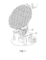
- Fig. 1 is a perspective view of an antenna device 1 according one embodiment of this disclosure.
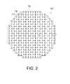
- Fig. 2 is a planar view of an antenna 10.
- the antenna device 1 configures a radar apparatus along with a non-illustrated radio wave generator (e.g., a magnetron), a controller and the like.
- the antenna device 1 is used, for example, for meteorological observation; however, it can also be used for other applications (e.g., communication).
- the antenna device 1 includes the antenna 10, a transmission part 20, and a pedestal 50.
- the antenna 10 is configured to be rotatable in vertical directions (directions of changing an elevation angle) and horizontal directions (directions of changing an azimuth).
- the pedestal 50 has legs and a supporting plate fixed to the legs. Respective components (e.g., a gear and a waveguide) configuring the transmission part 20 are attached to this supporting plate. Further, a motor (not illustrated) configured to rotate the antenna 10 in the vertical directions and a motor (not illustrated) configured to rotate the antenna 10 in the horizontal directions are attached to this pedestal 50.
- a motor not illustrated
- a motor not illustrated
- the transmission part 20 can rotate the antenna 10 in the vertical and horizontal directions by using gears and the like to transmit powers of these motors.
- the transmission part 20 includes a non-illustrated waveguide configured to transmit, to the antenna 10, a radio wave (electromagnetic wave) generated by the radio wave generator.
- the antenna 10 includes a radiation waveguide part 11 and probes 18.
- This radiation waveguide part 11 has a front-face metal plate 15 and a back-face metal plate 16.
- the front-face metal plate 15 is a member forming a front face (radio wave reflection face) of the radiation waveguide part 11. Slots 17 are formed and probes 18 are disposed in the front surface of this front-face metal plate 15. The slots 17 and the probes 18 are described later in detail.
- the back-face metal plate 16 is a member forming a back face (opposite face to the radio reflection face) of the radiation waveguide part 11.
- non-illustrated opening(s) are formed to connect with, for example, the waveguide of the transmission part 20.
- End parts of the front-face metal plate 15 and the back-face metal plate 16 are attached, at their end portions, by a fixing member 31 as illustrated in the cross-sectional view of Fig. 3(B) .
- the front-face metal plate 15 is bent (stamped) at three positions, and channel-shaped portions (substantially U-shaped portions) 15a and a connecting portion 15b are formed.
- the channel-shaped portions 15a form a side face of the radiation waveguide part 11.
- the connecting portion 15b is used to connect the front-face metal plate 15 with the back-face metal plate 16.
- the back-face metal plate 16 is bent at one position, and a connecting portion 16a is formed.
- This connecting portion 16a is attached to the connecting portion 15b by the fixing member 31 described above.
- the opening part is closed by, for example a metal tape.
- the slots 17 are penetrating holes for radiating outside a radio wave propagated inside the space of the radiation waveguide part 11. Moreover, each slot 17 is a long hole and formed to be arrayed in longitudinal and lateral directions thereof (see Fig. 2 ). Moreover, an arrangement interval of the slot 17 with another one in its longitudinal direction and an arrangement interval of the slot 17 with another one in its lateral direction are respectively fixed.
- the probes 18 are cylindrical members. Each probe 18 is attached on either one of sides of slot 17 in the lateral direction, for every slot 17. Moreover, whether the probe 18 is formed on the side or the other side in the lateral direction is different (the probes 18 are alternately disposed) between the slots adjacent to each other in up-and-down directions or left-and-right directions. As illustrated in Fig. 3(A) , the probes 18 are disposed to extend from the front-face metal plate 15 toward the back-face metal plate 16.
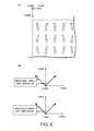
- the transmission mode of the radio wave in the space of the radiation waveguide part 11 can be changed. Therefore, even when the slots 17 are arrayed symmetrically as described above, the radio waves to be radiated can be prevented from cancelling each other out. Moreover, since the slots 17 are arrayed symmetrically, occurrence of side lobes in the directions illustrated in Fig. 6(B) can be suppressed. Thus, the radio wave suppressed in occurrence of side lobes can be radiated outside from the radiation waveguide part 11.
- the radio wave radiated by the radiation waveguide part 11 reflects on rain, cloud and the like.
- the antenna device 1 receives this reflection wave in a reverse flow inside the path of the radio wave described above. Then, for example, the controller of the radar apparatus analyzes this reflection wave and, thus, the antenna device 1 can obtain position, size, and density of water droplet.
- FIG. 4 shows views for describing a part of a flow of manufacturing the antenna 10 (particularly the radiation waveguide part 11).
- the front-face metal plate 15 cut into a predetermined shape is prepared ( Fig. 4(A) ). Then, the slots 17 are formed in the back face of this front-face metal plate 15 by, for example, turret punch press ( Fig. 4(B) ).
- the probes 18 are piled (press-fitted; Fig. 4(D) ) from the back surface of the front-face metal plate 15 by a press-fitting machine, for example.
- burrs may be created in a face opposite to the worked face. The burrs created in the metal plate can easily be removed; however, if the burrs exist in the space of the radiation waveguide part 11, the radio wave propagating in this space may be slightly distorted.
- the configuration is adopted, in which the probes 18 are piled from the back face of the front-face metal plate 15; therefore, the existence of burrs in the space of the radiation waveguide part 11 can surely be prevented.
- the front-face metal plate 15 is connected with the back-face metal plate 16 as described above.
- the radiation waveguide part 11 can be created.
- the manufacturing method given here is an example, and, for example, the order of the flow and the machine utilized in each step of the flow can suitably be changed. For example, the step of forming the slots 17 and the step of press-fitting the probes 18 can be switched.
- the probes 18 prevent the radio waves to be radiated from cancelling each other out.
- the example given in the above embodiment is not necessarily optimal, and it is considered that an antenna property and the like are improved by suitably changing them.
- the position where the probe 18 is formed (a distance between the slot 17 and the probe 18) may be changed according to, for example, the piled position, instead of the position being fixed.
- the size or the shape of the probe, or whether to pile may be changed.
- a configuration may be adopted, in which the size or the shape changes according to the piled position.
- the probe 18 may have, as a probe 18a in Fig. 5(A) , a shape (T-shape) in which the diameter of a part fixed to the front-face metal plate 15 is larger than other part (the part protruding inward of the radiation waveguide part 11). Moreover, the probe 18 may have, as a probe 18b in Fig. 5(B) , a shape in which the diameter of a part fixed to the front-face metal plate 15 is smaller than the other part.
- the probes 18 may be disposed such that the probes 18a are adjacent to each other, or the probes 18b are adjacent to each other. Moreover, the probe 18a and the probe 18b may be disposed adjacent to each other. Note that, when disposing the probes 18a to be adjacent, since the parts having large diameters interfere with each other, a distance d between the probes is restricted.
- the antenna 10 includes a radiation waveguide part 11 and the probes 18.
- the radiation waveguide part 11 has the two sheets of metal plates opposing to each other, and the radio wave is radiated outside from the plurality of slots 17 formed in one of the metal plates.
- Each probe 18 is disposed for every slot 17 to extend inward of the radiation waveguide part 11 from the face where the slots 17 are formed, and changes the transmission mode of the radio wave inside the radiation waveguide part 11.
- the slots 17 are narrow and arranged at fixed intervals in the longitudinal direction and in the lateral direction, respectively.
- the probe 18 is disposed for every slot 17, on either one of the sides of the slot 17 in the lateral direction. With the adjacent slots 17, the probes are disposed on the opposite sides in the lateral direction.
- the radiation waveguide part 11 is not limited to have the configuration in which the metal plates are directly coupled to each other, and may be coupled to each other via other member.
- the radiation waveguide part 11 may be formed by connecting the front-face metal plate 15 bent a plurality of times and the back-face metal plate 16 that is not bent.
- the probe 18 is not limited to have the configuration of being mechanically press-fitted, and may have a configuration of being attached by a person with a thread, for example.
- the shape of the probe 18 is also not limited to the configuration described above and may be any arbitrary shape.
Landscapes
- Engineering & Computer Science (AREA)
- Radar, Positioning & Navigation (AREA)
- Remote Sensing (AREA)
- Physics & Mathematics (AREA)
- Electromagnetism (AREA)
- Computer Networks & Wireless Communication (AREA)
- General Physics & Mathematics (AREA)
- Waveguide Aerials (AREA)
- Variable-Direction Aerials And Aerial Arrays (AREA)
Abstract
Description
- This disclosure relates to a slot array antenna where slots are arrayed in two directions.
- Conventionally, antennas having a configuration in which two sheets of conductive plates having conductivity are disposed at a predetermined distance from each other, and slots are formed in one of the conductive plates have been known. With this configuration, radio waves propagated between the two sheets of conductive plates are radiated outside from the slots.
Patent Document 1 discloses an antenna similar to such kind of antennas. -
Patent Document 1 discloses a microstrip antenna having a configuration formed with a plurality of probes formed to pass through the center of the conductive plates. InPatent Document 1, an effect that a radiating direction of a beam can be substantially matched with normal directions of the conductive plates, an effect that a frequency property of the antenna improves, and the like by forming the probes as above, are disclosed. - Patent Document 2 discloses a slot array antenna where slots are arrayed in one direction. In Patent Document 2, a probe is disposed inside a coaxial waveguide converter. By disposing the probe as above, a mode of an electromagnetic wave to be transmitted can be switched.
-
- Patent Document 1: JPH11-088043A
- Patent Document 2:
JP2005-073212A - Meanwhile, the microstrip antenna of
Patent Document 1 can suppress occurrence of a side lobe to some extent by disposing the probes as described above. - Whereas, with slot array antennas, if slots are arranged parallely at a fixed interval of the slots, radio waves interfere, cancel each other out, and will not be radiated. Therefore, conventionally, by forming inclined slots (
Fig. 6(A) ) or differentiating the interval at which the slots are formed, the radio waves are radiated. - However, for such a slot array antenna, since the slots are not arranged symmetrically, it is known that side lobes are produced in the directions illustrated in
Fig. 6(B) . - This disclosure is made in view of the above situations and aims to provide a slot array antenna where slots are arrayed in two directions, which has a configuration capable of suppressing occurrence of side lobes and suppressed in weight.
- Problems to be solved by the present disclosure are described above, and means for solving the problems and effects thereof will be described below.
- According to a first aspect of this disclosure, an antenna with the following configuration is provided. That is, the antenna includes a radiation waveguide part and probes. The radiation waveguide part includes two sheets of metal plates facing each other and outwardly radiates a radio wave from a plurality of slots formed in one of the metal plates. Each probe is arranged for every slot to extend inward of the radiation waveguide part from a face of the radiation waveguide part where the slots are formed, and changes a transmission mode of the radio wave within the radiation waveguide part. The slots are narrow and arranged at fixed intervals in a longitudinal direction of the slots and in a lateral direction of the slots, respectively. The probe is disposed for every slot, on either one of sides of the slot in the lateral direction, the adjacent probes in the lateral direction being disposed on the opposite sides.
- Thereby, the radio waves can be prevented from cancelling each other out while the slots are arrayed symmetrically, and thus, occurrence of unnecessary lobes can be suppressed. Further, since the radiation waveguide part is made of the metal plates, the radiation waveguide part can be reduced in weight and the attaching of the probe becomes easy. Further, since the probes are attached to the face where the slots are formed, the number of the metal plates that require processing can be one, and as a result, the manufacturing process of the antenna can be simple. Furthermore, since the antenna is made of metal plates, the weight can be reduced considerably compared with antennas formed with the conventional manufacturing methods such as casting, etc.
- In the antenna, the probe preferably has a circular cylindrical shape, and the probe is preferably press-fitted into the radiation waveguide part mechanically.
- Thereby, the probes can be attached easily and accurately by forming the probe into the circular cylindrical shape suitable for press-fitting and by using, for example, a press fitting machine to mechanically press-fit the probe. Specifically, since the radiation waveguide part of this disclosure is made of the metal plates, it can be processed promptly.
- The antenna is preferably configured as follows. That is, the radiation waveguide part is formed by the front-face metal plate forming at least a front face of the radiation waveguide part and the back-face metal plate forming at least a back face of the radiation waveguide part. At least one of the front-face metal plate and the back-face metal plate is bent, and by utilizing the bent portion, the front-face metal plate is connected with the back-face metal plate.
- Thereby, for example, plate members connecting the two sheets of metal plates become unnecessary. Further, since metal plates are easy to be bent (stamped), the costs of processing and assembling can be reduced.
- In the antenna, an interval between the slot and the probe is preferably different depending on the position of the probe on the radiation waveguide part.
- Thereby, the intensity of the radio wave to be radiated can be adjusted.
- The antenna is preferably used for meteorological observation.
- Thereby, the effects of this disclosure can be exerted with an antenna for meteorological observation. Especially, in this disclosure, since the radiation waveguide part is made of metal plates as described above, the weight is reduced. Therefore, the workability can be improved when arranging a plurality of radars collectively.
- According to a second aspect of this disclosure, a method of manufacturing an antenna described as follows is provided. That is, the method of manufacturing the antenna includes forming slots in a front-face metal plate configured to form a front face of a radiation waveguide part such that the slots are arranged at fixed intervals in a longitudinal direction of the slots and in a lateral direction of the slots, respectively. The method includes piling a probe from a back side of the front-face metal plate for every slot, on either one of sides of the slot in the lateral direction. The method includes connecting the front-face metal plate with a back-face metal plate configured to form a back face of the radiation waveguide part.
- The antenna manufactured by the method described above can prevent occurrence of unnecessary lobes. Further, since the probe is piled from the back side of the front-face metal plate, burrs are positioned on an outer side (front face) of the radiation waveguide part. Therefore, it is unnecessary to remove the burrs accurately, and thus, the antenna can be manufactured effectively.
-
-
Fig. 1 is a perspective view of an antenna device according one embodiment of this disclosure. -
Fig. 2 is a planar view of an antenna. -
Fig. 3 shows cross-sectional views a center part and an end part of the antenna, respectively. -
Fig. 4 shows views for describing a part of a flow of manufacturing the antenna. -
Fig. 5 shows views illustrating an example of a shape of probes and combinations thereof. -
Fig. 6 shows views illustrating an arrangement of slots of a conventional antenna and a direction of side lobes that occurs with the antenna. - Next, an embodiment of this disclosure is described with reference to the drawings.
Fig. 1 is a perspective view of anantenna device 1 according one embodiment of this disclosure.Fig. 2 is a planar view of anantenna 10. - The
antenna device 1 configures a radar apparatus along with a non-illustrated radio wave generator (e.g., a magnetron), a controller and the like. Theantenna device 1 is used, for example, for meteorological observation; however, it can also be used for other applications (e.g., communication). - As illustrated in
Fig. 1 , theantenna device 1 includes theantenna 10, atransmission part 20, and apedestal 50. Theantenna 10 is configured to be rotatable in vertical directions (directions of changing an elevation angle) and horizontal directions (directions of changing an azimuth). - The
pedestal 50 has legs and a supporting plate fixed to the legs. Respective components (e.g., a gear and a waveguide) configuring thetransmission part 20 are attached to this supporting plate. Further, a motor (not illustrated) configured to rotate theantenna 10 in the vertical directions and a motor (not illustrated) configured to rotate theantenna 10 in the horizontal directions are attached to thispedestal 50. - The
transmission part 20 can rotate theantenna 10 in the vertical and horizontal directions by using gears and the like to transmit powers of these motors. Moreover, thetransmission part 20 includes a non-illustrated waveguide configured to transmit, to theantenna 10, a radio wave (electromagnetic wave) generated by the radio wave generator. - The
antenna 10 includes aradiation waveguide part 11 and probes 18. This radiation waveguidepart 11 has a front-face metal plate 15 and a back-face metal plate 16. - The front-
face metal plate 15 is a member forming a front face (radio wave reflection face) of theradiation waveguide part 11.Slots 17 are formed and probes 18 are disposed in the front surface of this front-face metal plate 15. Theslots 17 and theprobes 18 are described later in detail. - The back-
face metal plate 16 is a member forming a back face (opposite face to the radio reflection face) of theradiation waveguide part 11. In this back-face metal plate 16, non-illustrated opening(s) are formed to connect with, for example, the waveguide of thetransmission part 20. - End parts of the front-
face metal plate 15 and the back-face metal plate 16 are attached, at their end portions, by a fixingmember 31 as illustrated in the cross-sectional view ofFig. 3(B) . - Specifically, the front-
face metal plate 15 is bent (stamped) at three positions, and channel-shaped portions (substantially U-shaped portions) 15a and a connectingportion 15b are formed. The channel-shapedportions 15a form a side face of theradiation waveguide part 11. The connectingportion 15b is used to connect the front-face metal plate 15 with the back-face metal plate 16. - Moreover, the back-
face metal plate 16 is bent at one position, and a connectingportion 16a is formed. This connectingportion 16a is attached to the connectingportion 15b by the fixingmember 31 described above. Moreover, although a part of the side face of theradiation waveguide part 11 is opened even when the front-shape metal plate 15 is attached to the back-face metal plate 16 as described above, the opening part is closed by, for example a metal tape. - As above, in the
radiation waveguide part 11, a space surrounded by conductive members can be achieved. - The
slots 17 are penetrating holes for radiating outside a radio wave propagated inside the space of theradiation waveguide part 11. Moreover, eachslot 17 is a long hole and formed to be arrayed in longitudinal and lateral directions thereof (seeFig. 2 ). Moreover, an arrangement interval of theslot 17 with another one in its longitudinal direction and an arrangement interval of theslot 17 with another one in its lateral direction are respectively fixed. - The
probes 18 are cylindrical members. Eachprobe 18 is attached on either one of sides ofslot 17 in the lateral direction, for everyslot 17. Moreover, whether theprobe 18 is formed on the side or the other side in the lateral direction is different (theprobes 18 are alternately disposed) between the slots adjacent to each other in up-and-down directions or left-and-right directions. As illustrated inFig. 3(A) , theprobes 18 are disposed to extend from the front-face metal plate 15 toward the back-face metal plate 16. - With this configuration, the transmission mode of the radio wave in the space of the
radiation waveguide part 11 can be changed. Therefore, even when theslots 17 are arrayed symmetrically as described above, the radio waves to be radiated can be prevented from cancelling each other out. Moreover, since theslots 17 are arrayed symmetrically, occurrence of side lobes in the directions illustrated inFig. 6(B) can be suppressed. Thus, the radio wave suppressed in occurrence of side lobes can be radiated outside from theradiation waveguide part 11. - The radio wave radiated by the
radiation waveguide part 11 reflects on rain, cloud and the like. Theantenna device 1 receives this reflection wave in a reverse flow inside the path of the radio wave described above. Then, for example, the controller of the radar apparatus analyzes this reflection wave and, thus, theantenna device 1 can obtain position, size, and density of water droplet. - Next, a method of forming the
slots 17 and theprobes 18 in the front-face metal plate 15 is described above.Fig. 4 shows views for describing a part of a flow of manufacturing the antenna 10 (particularly the radiation waveguide part 11). - First, the front-
face metal plate 15 cut into a predetermined shape is prepared (Fig. 4(A) ). Then, theslots 17 are formed in the back face of this front-face metal plate 15 by, for example, turret punch press (Fig. 4(B) ). - Next, by bending (stamping) the front-
face metal plate 15 as described above, the channel-shapedportions 15a and the connectingportion 15b are formed (Fig. 4(C) ). - Next, the
probes 18 are piled (press-fitted;Fig. 4(D) ) from the back surface of the front-face metal plate 15 by a press-fitting machine, for example. Moreover, in the press-fitting work, burrs may be created in a face opposite to the worked face. The burrs created in the metal plate can easily be removed; however, if the burrs exist in the space of theradiation waveguide part 11, the radio wave propagating in this space may be slightly distorted. In this regard, in this embodiment, the configuration is adopted, in which theprobes 18 are piled from the back face of the front-face metal plate 15; therefore, the existence of burrs in the space of theradiation waveguide part 11 can surely be prevented. - Then, the front-
face metal plate 15 is connected with the back-face metal plate 16 as described above. As described above, theradiation waveguide part 11 can be created. Note that, the manufacturing method given here is an example, and, for example, the order of the flow and the machine utilized in each step of the flow can suitably be changed. For example, the step of forming theslots 17 and the step of press-fitting theprobes 18 can be switched. - Next, another example of the
probes 18 is described. In this embodiment, a configuration in which theprobes 18 prevent the radio waves to be radiated from cancelling each other out is adopted. Here, as for the position, size, and shape and the like of theprobes 18, the example given in the above embodiment is not necessarily optimal, and it is considered that an antenna property and the like are improved by suitably changing them. - For example, the position where the
probe 18 is formed (a distance between theslot 17 and the probe 18) may be changed according to, for example, the piled position, instead of the position being fixed. Moreover, the size or the shape of the probe, or whether to pile may be changed. Further, a configuration may be adopted, in which the size or the shape changes according to the piled position. By changing the distance between theslot 17 and theprobe 18, the strength of the radio wave to be radiated from theantenna 10 can be changed. - The
probe 18 may have, as aprobe 18a inFig. 5(A) , a shape (T-shape) in which the diameter of a part fixed to the front-face metal plate 15 is larger than other part (the part protruding inward of the radiation waveguide part 11). Moreover, theprobe 18 may have, as aprobe 18b inFig. 5(B) , a shape in which the diameter of a part fixed to the front-face metal plate 15 is smaller than the other part. - As a combination of the
probes 18, they may be disposed such that theprobes 18a are adjacent to each other, or theprobes 18b are adjacent to each other. Moreover, theprobe 18a and theprobe 18b may be disposed adjacent to each other. Note that, when disposing theprobes 18a to be adjacent, since the parts having large diameters interfere with each other, a distance d between the probes is restricted. - Moreover, even when the
probe 18 is formed into a planar plate instead of a pillar shape, the effect of this application can be exerted. However, by forming into the pillar shape, whether to pile can be controlled finely, and therefore, satisfactory antenna property can possibly be obtained. - As described above, the
antenna 10 includes aradiation waveguide part 11 and theprobes 18. The radiation waveguidepart 11 has the two sheets of metal plates opposing to each other, and the radio wave is radiated outside from the plurality ofslots 17 formed in one of the metal plates. Eachprobe 18 is disposed for everyslot 17 to extend inward of theradiation waveguide part 11 from the face where theslots 17 are formed, and changes the transmission mode of the radio wave inside theradiation waveguide part 11. Theslots 17 are narrow and arranged at fixed intervals in the longitudinal direction and in the lateral direction, respectively. Theprobe 18 is disposed for everyslot 17, on either one of the sides of theslot 17 in the lateral direction. With theadjacent slots 17, the probes are disposed on the opposite sides in the lateral direction. - Although the preferred embodiment of this disclosure is described above, the above configurations may be modified as follows, for example.
- The radiation waveguide
part 11 is not limited to have the configuration in which the metal plates are directly coupled to each other, and may be coupled to each other via other member. - The radiation waveguide
part 11 may be formed by connecting the front-face metal plate 15 bent a plurality of times and the back-face metal plate 16 that is not bent. - The
probe 18 is not limited to have the configuration of being mechanically press-fitted, and may have a configuration of being attached by a person with a thread, for example. Moreover, the shape of theprobe 18 is also not limited to the configuration described above and may be any arbitrary shape. -
- 1
- Antenna Device
- 10
- Antenna
- 11
- Radiation Waveguide Part
- 15
- Front-face Metal Plate
- 16
- Back-face Metal Plate
- 17
- Slot
- 18
- Probe
Claims (6)
- An antenna, comprising:a radiation waveguide part including two sheets of metal plates facing each other and configured to outwardly radiate a radio wave from a plurality of slots formed in one of the metal plates; anda probe arranged for every slot to extend inward of the radiation waveguide part from a face of the radiation waveguide part where the slots are formed, and configured to change a transmission mode of the radio wave within the radiation waveguide part,wherein the slots are narrow and arranged at fixed intervals in a longitudinal direction of the slots and in a lateral direction of the slots, respectively, andwherein the probe is disposed for every slot, on either one of sides of the slot in the lateral direction, the adjacent probes in the lateral direction being disposed on the opposite sides.
- The antenna of Claim 1, wherein the probe has a circular cylindrical shape,and
wherein the probe is mechanically press-fitted into the radiation waveguide part. - The antenna of Claim 1 or 2, wherein the radiation waveguide part is formed by the front-face metal plate forming at least a front face of the radiation waveguide part and the back-face metal plate forming at least a back face of the radiation waveguide part, and
wherein at least one of the front-face metal plate and the back-face metal plate is bent, and by utilizing the bent portion, the front-face metal plate is connected with the back-face metal plate. - The antenna of any one of Claims 1 to 3, wherein an interval between the slot and the probe is different depending on the position of the probe on the radiation waveguide part.
- The antenna of any one of Claims 1 to 4, wherein the antenna is used for meteorological observation.
- A method of manufacturing an antenna, comprising:forming slots in a front-face metal plate configured to form a front face of a radiation waveguide part such that the slots are arranged at fixed intervals in a longitudinal direction of the slots and in a lateral direction of the slots, respectively;piling a probe from a back side of the front-face metal plate for every slot, on either one of sides of the slot in the lateral direction; andconnecting the front-face metal plate with a back-face metal plate configured to form a back face of the radiation waveguide part.
Applications Claiming Priority (2)
| Application Number | Priority Date | Filing Date | Title |
|---|---|---|---|
| JP2012084034 | 2012-04-02 | ||
| PCT/JP2013/059844 WO2013150995A1 (en) | 2012-04-02 | 2013-04-01 | Antenna and manufacturing method for antenna |
Publications (3)
| Publication Number | Publication Date |
|---|---|
| EP2835867A1 true EP2835867A1 (en) | 2015-02-11 |
| EP2835867A4 EP2835867A4 (en) | 2015-12-02 |
| EP2835867B1 EP2835867B1 (en) | 2022-11-16 |
Family
ID=49300478
Family Applications (1)
| Application Number | Title | Priority Date | Filing Date |
|---|---|---|---|
| EP13772217.9A Active EP2835867B1 (en) | 2012-04-02 | 2013-04-01 | Antenna and manufacturing method for antenna |
Country Status (5)
| Country | Link |
|---|---|
| US (1) | US9728859B2 (en) |
| EP (1) | EP2835867B1 (en) |
| JP (1) | JP5895047B2 (en) |
| CN (1) | CN104205495B (en) |
| WO (1) | WO2013150995A1 (en) |
Families Citing this family (2)
| Publication number | Priority date | Publication date | Assignee | Title |
|---|---|---|---|---|
| WO2013098795A1 (en) * | 2011-12-29 | 2013-07-04 | Selex Galileo S.P.A. | Slotted waveguide antenna for near-field focalization of electromagnetic radiation |
| WO2013123089A1 (en) * | 2012-02-17 | 2013-08-22 | Cohen Nathaniel L | Apparatus for using microwave energy for insect and pest control and methods thereof |
Family Cites Families (11)
| Publication number | Priority date | Publication date | Assignee | Title |
|---|---|---|---|---|
| US3369244A (en) | 1965-03-01 | 1968-02-13 | Melpar Inc | Multi-channel slot antenna for ultra high frequencies |
| US3599216A (en) * | 1969-08-11 | 1971-08-10 | Nasa | Virtual-wall slot circularly polarized planar array antenna |
| US3716868A (en) | 1970-10-20 | 1973-02-13 | Westinghouse Electric Corp | Broadband slotted waveguide antenna array |
| US5289200A (en) * | 1992-09-28 | 1994-02-22 | Hughes Aircraft Company | Tab coupled slots for waveguide fed slot array antennas |
| JP3364829B2 (en) * | 1997-09-05 | 2003-01-08 | 三菱電機株式会社 | Antenna device |
| JP4164807B2 (en) * | 2003-08-20 | 2008-10-15 | 太洋無線株式会社 | Slot array antenna |
| JP2005073121A (en) | 2003-08-27 | 2005-03-17 | Mega Chips Corp | Radio communication apparatus |
| US7202832B2 (en) * | 2004-01-07 | 2007-04-10 | Motia | Vehicle mounted satellite antenna system with ridged waveguide |
| JP5261628B2 (en) * | 2008-08-29 | 2013-08-14 | 日本無線株式会社 | Waveguide slot array antenna |
| JP5219139B2 (en) * | 2008-10-24 | 2013-06-26 | 国立大学法人東京工業大学 | Waveguide slot array antenna, waveguide slot array antenna design method, and waveguide slot array antenna manufacturing method |
| JP5558943B2 (en) * | 2010-07-06 | 2014-07-23 | 古野電気株式会社 | Slot array antenna and radar device |
-
2013
- 2013-04-01 JP JP2014509146A patent/JP5895047B2/en not_active Expired - Fee Related
- 2013-04-01 WO PCT/JP2013/059844 patent/WO2013150995A1/en not_active Ceased
- 2013-04-01 EP EP13772217.9A patent/EP2835867B1/en active Active
- 2013-04-01 CN CN201380017537.2A patent/CN104205495B/en not_active Expired - Fee Related
- 2013-04-01 US US14/390,370 patent/US9728859B2/en not_active Expired - Fee Related
Also Published As
| Publication number | Publication date |
|---|---|
| CN104205495A (en) | 2014-12-10 |
| US20150029055A1 (en) | 2015-01-29 |
| JP5895047B2 (en) | 2016-03-30 |
| JPWO2013150995A1 (en) | 2015-12-17 |
| CN104205495B (en) | 2017-12-05 |
| US9728859B2 (en) | 2017-08-08 |
| EP2835867B1 (en) | 2022-11-16 |
| EP2835867A4 (en) | 2015-12-02 |
| WO2013150995A1 (en) | 2013-10-10 |
Similar Documents
| Publication | Publication Date | Title |
|---|---|---|
| EP4020714B1 (en) | Folded waveguide for antenna | |
| JP5930517B2 (en) | Antenna device | |
| EP3220481B1 (en) | Waveguide slot array antenna | |
| EP2955787B1 (en) | Antenna device and array antenna device | |
| EP1950832B1 (en) | Rectilinear polarization antenna and radar device using the same | |
| JP2016058790A (en) | Array antenna and device using the same | |
| EP2058900A1 (en) | Multibeam antenna | |
| EP3460907B1 (en) | Array antenna device | |
| US11978956B2 (en) | Antenna arrangements and microwave devices with improved attachment means | |
| US20180123254A1 (en) | Single-layered end-fire circularly polarized substrate integrated waveguide horn antenna | |
| US8593369B2 (en) | Antenna assembly | |
| CA2915707C (en) | Augmented e-plane taper techniques in variable inclination continuous transverse stub antenna arrays | |
| EP3701280B1 (en) | Radar sensor having a plurality of main beam directions | |
| EP1690318B1 (en) | Scanable sparse array antenna | |
| JP2009111463A (en) | Antenna device | |
| JP6738778B2 (en) | Radar equipment | |
| CN102255144B (en) | Radiating unit, radiating array and machining forming method | |
| CN202121061U (en) | Radiation unit and radiation array | |
| US9728859B2 (en) | Antenna and method of manufacturing the antenna | |
| US10230172B1 (en) | Thin metal ultra-wideband antenna array systems and methods | |
| US20180115076A1 (en) | Waveguide antenna assembly and system with mode barrier filter for electronic devices | |
| JP6014473B2 (en) | Radar antenna and method for manufacturing radar antenna | |
| JP2012122801A (en) | Antenna for radar, and radar device | |
| EP2849285B1 (en) | Ultra-broadband antenna array with constant beamwidth throughout operating frequency band | |
| KR100662733B1 (en) | Waveguide Slot Antenna |
Legal Events
| Date | Code | Title | Description |
|---|---|---|---|
| PUAI | Public reference made under article 153(3) epc to a published international application that has entered the european phase |
Free format text: ORIGINAL CODE: 0009012 |
|
| 17P | Request for examination filed |
Effective date: 20140930 |
|
| AK | Designated contracting states |
Kind code of ref document: A1 Designated state(s): AL AT BE BG CH CY CZ DE DK EE ES FI FR GB GR HR HU IE IS IT LI LT LU LV MC MK MT NL NO PL PT RO RS SE SI SK SM TR |
|
| AX | Request for extension of the european patent |
Extension state: BA ME |
|
| DAX | Request for extension of the european patent (deleted) | ||
| RA4 | Supplementary search report drawn up and despatched (corrected) |
Effective date: 20151030 |
|
| RIC1 | Information provided on ipc code assigned before grant |
Ipc: H01Q 13/22 20060101ALI20151026BHEP Ipc: H01Q 21/00 20060101ALI20151026BHEP Ipc: H01Q 21/06 20060101ALI20151026BHEP Ipc: H01P 11/00 20060101AFI20151026BHEP |
|
| RIC1 | Information provided on ipc code assigned before grant |
Ipc: H01Q 21/06 20060101ALI20151210BHEP Ipc: H01Q 13/22 20060101ALI20151210BHEP Ipc: H01Q 21/00 20060101ALI20151210BHEP Ipc: H01P 11/00 20060101AFI20151210BHEP |
|
| STAA | Information on the status of an ep patent application or granted ep patent |
Free format text: STATUS: EXAMINATION IS IN PROGRESS |
|
| 17Q | First examination report despatched |
Effective date: 20190523 |
|
| GRAP | Despatch of communication of intention to grant a patent |
Free format text: ORIGINAL CODE: EPIDOSNIGR1 |
|
| STAA | Information on the status of an ep patent application or granted ep patent |
Free format text: STATUS: GRANT OF PATENT IS INTENDED |
|
| INTG | Intention to grant announced |
Effective date: 20220608 |
|
| GRAS | Grant fee paid |
Free format text: ORIGINAL CODE: EPIDOSNIGR3 |
|
| GRAA | (expected) grant |
Free format text: ORIGINAL CODE: 0009210 |
|
| STAA | Information on the status of an ep patent application or granted ep patent |
Free format text: STATUS: THE PATENT HAS BEEN GRANTED |
|
| AK | Designated contracting states |
Kind code of ref document: B1 Designated state(s): AL AT BE BG CH CY CZ DE DK EE ES FI FR GB GR HR HU IE IS IT LI LT LU LV MC MK MT NL NO PL PT RO RS SE SI SK SM TR |
|
| REG | Reference to a national code |
Ref country code: GB Ref legal event code: FG4D |
|
| REG | Reference to a national code |
Ref country code: CH Ref legal event code: EP |
|
| REG | Reference to a national code |
Ref country code: IE Ref legal event code: FG4D |
|
| REG | Reference to a national code |
Ref country code: DE Ref legal event code: R096 Ref document number: 602013082877 Country of ref document: DE |
|
| REG | Reference to a national code |
Ref country code: AT Ref legal event code: REF Ref document number: 1532329 Country of ref document: AT Kind code of ref document: T Effective date: 20221215 |
|
| REG | Reference to a national code |
Ref country code: LT Ref legal event code: MG9D |
|
| REG | Reference to a national code |
Ref country code: NL Ref legal event code: MP Effective date: 20221116 |
|
| REG | Reference to a national code |
Ref country code: AT Ref legal event code: MK05 Ref document number: 1532329 Country of ref document: AT Kind code of ref document: T Effective date: 20221116 |
|
| PG25 | Lapsed in a contracting state [announced via postgrant information from national office to epo] |
Ref country code: SE Free format text: LAPSE BECAUSE OF FAILURE TO SUBMIT A TRANSLATION OF THE DESCRIPTION OR TO PAY THE FEE WITHIN THE PRESCRIBED TIME-LIMIT Effective date: 20221116 Ref country code: PT Free format text: LAPSE BECAUSE OF FAILURE TO SUBMIT A TRANSLATION OF THE DESCRIPTION OR TO PAY THE FEE WITHIN THE PRESCRIBED TIME-LIMIT Effective date: 20230316 Ref country code: NO Free format text: LAPSE BECAUSE OF FAILURE TO SUBMIT A TRANSLATION OF THE DESCRIPTION OR TO PAY THE FEE WITHIN THE PRESCRIBED TIME-LIMIT Effective date: 20230216 Ref country code: LT Free format text: LAPSE BECAUSE OF FAILURE TO SUBMIT A TRANSLATION OF THE DESCRIPTION OR TO PAY THE FEE WITHIN THE PRESCRIBED TIME-LIMIT Effective date: 20221116 Ref country code: FI Free format text: LAPSE BECAUSE OF FAILURE TO SUBMIT A TRANSLATION OF THE DESCRIPTION OR TO PAY THE FEE WITHIN THE PRESCRIBED TIME-LIMIT Effective date: 20221116 Ref country code: ES Free format text: LAPSE BECAUSE OF FAILURE TO SUBMIT A TRANSLATION OF THE DESCRIPTION OR TO PAY THE FEE WITHIN THE PRESCRIBED TIME-LIMIT Effective date: 20221116 Ref country code: AT Free format text: LAPSE BECAUSE OF FAILURE TO SUBMIT A TRANSLATION OF THE DESCRIPTION OR TO PAY THE FEE WITHIN THE PRESCRIBED TIME-LIMIT Effective date: 20221116 |
|
| PG25 | Lapsed in a contracting state [announced via postgrant information from national office to epo] |
Ref country code: RS Free format text: LAPSE BECAUSE OF FAILURE TO SUBMIT A TRANSLATION OF THE DESCRIPTION OR TO PAY THE FEE WITHIN THE PRESCRIBED TIME-LIMIT Effective date: 20221116 Ref country code: PL Free format text: LAPSE BECAUSE OF FAILURE TO SUBMIT A TRANSLATION OF THE DESCRIPTION OR TO PAY THE FEE WITHIN THE PRESCRIBED TIME-LIMIT Effective date: 20221116 Ref country code: LV Free format text: LAPSE BECAUSE OF FAILURE TO SUBMIT A TRANSLATION OF THE DESCRIPTION OR TO PAY THE FEE WITHIN THE PRESCRIBED TIME-LIMIT Effective date: 20221116 Ref country code: IS Free format text: LAPSE BECAUSE OF FAILURE TO SUBMIT A TRANSLATION OF THE DESCRIPTION OR TO PAY THE FEE WITHIN THE PRESCRIBED TIME-LIMIT Effective date: 20230316 Ref country code: HR Free format text: LAPSE BECAUSE OF FAILURE TO SUBMIT A TRANSLATION OF THE DESCRIPTION OR TO PAY THE FEE WITHIN THE PRESCRIBED TIME-LIMIT Effective date: 20221116 Ref country code: GR Free format text: LAPSE BECAUSE OF FAILURE TO SUBMIT A TRANSLATION OF THE DESCRIPTION OR TO PAY THE FEE WITHIN THE PRESCRIBED TIME-LIMIT Effective date: 20230217 |
|
| PG25 | Lapsed in a contracting state [announced via postgrant information from national office to epo] |
Ref country code: NL Free format text: LAPSE BECAUSE OF FAILURE TO SUBMIT A TRANSLATION OF THE DESCRIPTION OR TO PAY THE FEE WITHIN THE PRESCRIBED TIME-LIMIT Effective date: 20221116 |
|
| PG25 | Lapsed in a contracting state [announced via postgrant information from national office to epo] |
Ref country code: SM Free format text: LAPSE BECAUSE OF FAILURE TO SUBMIT A TRANSLATION OF THE DESCRIPTION OR TO PAY THE FEE WITHIN THE PRESCRIBED TIME-LIMIT Effective date: 20221116 Ref country code: RO Free format text: LAPSE BECAUSE OF FAILURE TO SUBMIT A TRANSLATION OF THE DESCRIPTION OR TO PAY THE FEE WITHIN THE PRESCRIBED TIME-LIMIT Effective date: 20221116 Ref country code: EE Free format text: LAPSE BECAUSE OF FAILURE TO SUBMIT A TRANSLATION OF THE DESCRIPTION OR TO PAY THE FEE WITHIN THE PRESCRIBED TIME-LIMIT Effective date: 20221116 Ref country code: DK Free format text: LAPSE BECAUSE OF FAILURE TO SUBMIT A TRANSLATION OF THE DESCRIPTION OR TO PAY THE FEE WITHIN THE PRESCRIBED TIME-LIMIT Effective date: 20221116 Ref country code: CZ Free format text: LAPSE BECAUSE OF FAILURE TO SUBMIT A TRANSLATION OF THE DESCRIPTION OR TO PAY THE FEE WITHIN THE PRESCRIBED TIME-LIMIT Effective date: 20221116 |
|
| REG | Reference to a national code |
Ref country code: DE Ref legal event code: R097 Ref document number: 602013082877 Country of ref document: DE |
|
| PG25 | Lapsed in a contracting state [announced via postgrant information from national office to epo] |
Ref country code: SK Free format text: LAPSE BECAUSE OF FAILURE TO SUBMIT A TRANSLATION OF THE DESCRIPTION OR TO PAY THE FEE WITHIN THE PRESCRIBED TIME-LIMIT Effective date: 20221116 Ref country code: AL Free format text: LAPSE BECAUSE OF FAILURE TO SUBMIT A TRANSLATION OF THE DESCRIPTION OR TO PAY THE FEE WITHIN THE PRESCRIBED TIME-LIMIT Effective date: 20221116 |
|
| PLBE | No opposition filed within time limit |
Free format text: ORIGINAL CODE: 0009261 |
|
| STAA | Information on the status of an ep patent application or granted ep patent |
Free format text: STATUS: NO OPPOSITION FILED WITHIN TIME LIMIT |
|
| 26N | No opposition filed |
Effective date: 20230817 |
|
| REG | Reference to a national code |
Ref country code: DE Ref legal event code: R119 Ref document number: 602013082877 Country of ref document: DE |
|
| PG25 | Lapsed in a contracting state [announced via postgrant information from national office to epo] |
Ref country code: SI Free format text: LAPSE BECAUSE OF FAILURE TO SUBMIT A TRANSLATION OF THE DESCRIPTION OR TO PAY THE FEE WITHIN THE PRESCRIBED TIME-LIMIT Effective date: 20221116 |
|
| REG | Reference to a national code |
Ref country code: CH Ref legal event code: PL |
|
| GBPC | Gb: european patent ceased through non-payment of renewal fee |
Effective date: 20230401 |
|
| PG25 | Lapsed in a contracting state [announced via postgrant information from national office to epo] |
Ref country code: LU Free format text: LAPSE BECAUSE OF NON-PAYMENT OF DUE FEES Effective date: 20230401 |
|
| REG | Reference to a national code |
Ref country code: BE Ref legal event code: MM Effective date: 20230430 |
|
| PG25 | Lapsed in a contracting state [announced via postgrant information from national office to epo] |
Ref country code: MC Free format text: LAPSE BECAUSE OF FAILURE TO SUBMIT A TRANSLATION OF THE DESCRIPTION OR TO PAY THE FEE WITHIN THE PRESCRIBED TIME-LIMIT Effective date: 20221116 |
|
| PG25 | Lapsed in a contracting state [announced via postgrant information from national office to epo] |
Ref country code: GB Free format text: LAPSE BECAUSE OF NON-PAYMENT OF DUE FEES Effective date: 20230401 |
|
| PG25 | Lapsed in a contracting state [announced via postgrant information from national office to epo] |
Ref country code: MC Free format text: LAPSE BECAUSE OF FAILURE TO SUBMIT A TRANSLATION OF THE DESCRIPTION OR TO PAY THE FEE WITHIN THE PRESCRIBED TIME-LIMIT Effective date: 20221116 Ref country code: LI Free format text: LAPSE BECAUSE OF NON-PAYMENT OF DUE FEES Effective date: 20230430 Ref country code: GB Free format text: LAPSE BECAUSE OF NON-PAYMENT OF DUE FEES Effective date: 20230401 Ref country code: FR Free format text: LAPSE BECAUSE OF NON-PAYMENT OF DUE FEES Effective date: 20230430 Ref country code: DE Free format text: LAPSE BECAUSE OF NON-PAYMENT OF DUE FEES Effective date: 20231103 Ref country code: CH Free format text: LAPSE BECAUSE OF NON-PAYMENT OF DUE FEES Effective date: 20230430 |
|
| REG | Reference to a national code |
Ref country code: IE Ref legal event code: MM4A |
|
| PG25 | Lapsed in a contracting state [announced via postgrant information from national office to epo] |
Ref country code: BE Free format text: LAPSE BECAUSE OF NON-PAYMENT OF DUE FEES Effective date: 20230430 |
|
| PG25 | Lapsed in a contracting state [announced via postgrant information from national office to epo] |
Ref country code: IE Free format text: LAPSE BECAUSE OF NON-PAYMENT OF DUE FEES Effective date: 20230401 |
|
| PG25 | Lapsed in a contracting state [announced via postgrant information from national office to epo] |
Ref country code: IE Free format text: LAPSE BECAUSE OF NON-PAYMENT OF DUE FEES Effective date: 20230401 |
|
| PG25 | Lapsed in a contracting state [announced via postgrant information from national office to epo] |
Ref country code: IT Free format text: LAPSE BECAUSE OF FAILURE TO SUBMIT A TRANSLATION OF THE DESCRIPTION OR TO PAY THE FEE WITHIN THE PRESCRIBED TIME-LIMIT Effective date: 20221116 |
|
| PG25 | Lapsed in a contracting state [announced via postgrant information from national office to epo] |
Ref country code: BG Free format text: LAPSE BECAUSE OF FAILURE TO SUBMIT A TRANSLATION OF THE DESCRIPTION OR TO PAY THE FEE WITHIN THE PRESCRIBED TIME-LIMIT Effective date: 20221116 |
|
| PG25 | Lapsed in a contracting state [announced via postgrant information from national office to epo] |
Ref country code: BG Free format text: LAPSE BECAUSE OF FAILURE TO SUBMIT A TRANSLATION OF THE DESCRIPTION OR TO PAY THE FEE WITHIN THE PRESCRIBED TIME-LIMIT Effective date: 20221116 |
|
| PG25 | Lapsed in a contracting state [announced via postgrant information from national office to epo] |
Ref country code: CY Free format text: LAPSE BECAUSE OF FAILURE TO SUBMIT A TRANSLATION OF THE DESCRIPTION OR TO PAY THE FEE WITHIN THE PRESCRIBED TIME-LIMIT; INVALID AB INITIO Effective date: 20130401 |
|
| PG25 | Lapsed in a contracting state [announced via postgrant information from national office to epo] |
Ref country code: HU Free format text: LAPSE BECAUSE OF FAILURE TO SUBMIT A TRANSLATION OF THE DESCRIPTION OR TO PAY THE FEE WITHIN THE PRESCRIBED TIME-LIMIT; INVALID AB INITIO Effective date: 20130401 |
|
| PG25 | Lapsed in a contracting state [announced via postgrant information from national office to epo] |
Ref country code: TR Free format text: LAPSE BECAUSE OF FAILURE TO SUBMIT A TRANSLATION OF THE DESCRIPTION OR TO PAY THE FEE WITHIN THE PRESCRIBED TIME-LIMIT Effective date: 20221116 |