EP2835199A1 - Tool holder device - Google Patents
Tool holder device Download PDFInfo
- Publication number
- EP2835199A1 EP2835199A1 EP12721878.2A EP12721878A EP2835199A1 EP 2835199 A1 EP2835199 A1 EP 2835199A1 EP 12721878 A EP12721878 A EP 12721878A EP 2835199 A1 EP2835199 A1 EP 2835199A1
- Authority
- EP
- European Patent Office
- Prior art keywords
- movable part
- tool holder
- holder device
- movement
- axial
- Prior art date
- Legal status (The legal status is an assumption and is not a legal conclusion. Google has not performed a legal analysis and makes no representation as to the accuracy of the status listed.)
- Granted
Links
- 230000007246 mechanism Effects 0.000 claims abstract description 14
- 238000004873 anchoring Methods 0.000 claims description 16
- 230000008878 coupling Effects 0.000 claims description 5
- 238000010168 coupling process Methods 0.000 claims description 5
- 238000005859 coupling reaction Methods 0.000 claims description 5
- 230000030279 gene silencing Effects 0.000 claims description 3
- 238000007789 sealing Methods 0.000 claims description 3
- 230000004323 axial length Effects 0.000 claims description 2
- 238000005553 drilling Methods 0.000 description 16
- 239000000463 material Substances 0.000 description 6
- 238000003754 machining Methods 0.000 description 5
- 238000004519 manufacturing process Methods 0.000 description 4
- 238000000034 method Methods 0.000 description 4
- 230000008569 process Effects 0.000 description 4
- 230000008859 change Effects 0.000 description 3
- 229910000906 Bronze Inorganic materials 0.000 description 2
- 239000010974 bronze Substances 0.000 description 2
- KUNSUQLRTQLHQQ-UHFFFAOYSA-N copper tin Chemical compound [Cu].[Sn] KUNSUQLRTQLHQQ-UHFFFAOYSA-N 0.000 description 2
- 238000005520 cutting process Methods 0.000 description 2
- 230000032798 delamination Effects 0.000 description 2
- 238000009826 distribution Methods 0.000 description 2
- 230000003213 activating effect Effects 0.000 description 1
- 230000032683 aging Effects 0.000 description 1
- 230000015556 catabolic process Effects 0.000 description 1
- 230000000295 complement effect Effects 0.000 description 1
- 239000002131 composite material Substances 0.000 description 1
- 230000007423 decrease Effects 0.000 description 1
- 230000003247 decreasing effect Effects 0.000 description 1
- 230000002950 deficient Effects 0.000 description 1
- 238000013461 design Methods 0.000 description 1
- 238000006073 displacement reaction Methods 0.000 description 1
- 230000000694 effects Effects 0.000 description 1
- 238000005516 engineering process Methods 0.000 description 1
- 230000007613 environmental effect Effects 0.000 description 1
- 239000000835 fiber Substances 0.000 description 1
- 239000007943 implant Substances 0.000 description 1
- 230000006872 improvement Effects 0.000 description 1
- 238000005304 joining Methods 0.000 description 1
- 239000000314 lubricant Substances 0.000 description 1
- 238000009740 moulding (composite fabrication) Methods 0.000 description 1
- 230000009467 reduction Effects 0.000 description 1
- 230000001105 regulatory effect Effects 0.000 description 1
- 238000011160 research Methods 0.000 description 1
- 239000000725 suspension Substances 0.000 description 1
- 238000012360 testing method Methods 0.000 description 1
- 238000012546 transfer Methods 0.000 description 1
- 238000003466 welding Methods 0.000 description 1
- 239000008207 working material Substances 0.000 description 1
Images


Classifications
-
- B—PERFORMING OPERATIONS; TRANSPORTING
- B23—MACHINE TOOLS; METAL-WORKING NOT OTHERWISE PROVIDED FOR
- B23B—TURNING; BORING
- B23B47/00—Constructional features of components specially designed for boring or drilling machines; Accessories therefor
- B23B47/34—Arrangements for removing chips out of the holes made; Chip- breaking arrangements attached to the tool
-
- B—PERFORMING OPERATIONS; TRANSPORTING
- B23—MACHINE TOOLS; METAL-WORKING NOT OTHERWISE PROVIDED FOR
- B23B—TURNING; BORING
- B23B2270/00—Details of turning, boring or drilling machines, processes or tools not otherwise provided for
- B23B2270/02—Use of a particular power source
- B23B2270/027—Pneumatics
-
- B—PERFORMING OPERATIONS; TRANSPORTING
- B23—MACHINE TOOLS; METAL-WORKING NOT OTHERWISE PROVIDED FOR
- B23B—TURNING; BORING
- B23B2270/00—Details of turning, boring or drilling machines, processes or tools not otherwise provided for
- B23B2270/54—Methods of turning, boring or drilling not otherwise provided for
-
- Y—GENERAL TAGGING OF NEW TECHNOLOGICAL DEVELOPMENTS; GENERAL TAGGING OF CROSS-SECTIONAL TECHNOLOGIES SPANNING OVER SEVERAL SECTIONS OF THE IPC; TECHNICAL SUBJECTS COVERED BY FORMER USPC CROSS-REFERENCE ART COLLECTIONS [XRACs] AND DIGESTS
- Y10—TECHNICAL SUBJECTS COVERED BY FORMER USPC
- Y10T—TECHNICAL SUBJECTS COVERED BY FORMER US CLASSIFICATION
- Y10T408/00—Cutting by use of rotating axially moving tool
- Y10T408/23—Cutting by use of rotating axially moving tool including means to cause Tool to progressively vibrate toward work
Definitions
- the present invention has application in the field of the machining operations of parts, particularly drilling operation, and relates to a tool holder device can be coupled to a machine or equipment by means of a machined shaft or cone for anchoring.
- the object proposed by the invention allows producing an axial vibratory movement with respect to the linear movement of the machine and transmitting it to the tool with rotation.
- Typical problems such as the generation of long and wound chips while drilling ductile materials and the appearance of undesired vibrations are examples of phenomena to be improved in the high productivity machining of industrial components, since they involve an increase in down-time, further resulting in losses due to the manufacturing of defective parts and even machine break-downs, therefore eliminating delamination, reducing burrs, decreasing cutting temperature and improving roughness in the drilling of aeronautical materials are goals of great interest for the companies of the sector.
- vibration assisted drilling There are inventions today which allow implementing this process, known as vibration assisted drilling.
- Said inventions can be classified depending on where can the vibration be applied, first being devices which obtain vibration in the tool without it rotating, secondly being devices which make the part or test piece to be perforated vibrate, and finally there are devices in which the tool rotates and vibrates simultaneously, a group in which the present invention is included.
- the last class of tool holder includes document US 6234728 (B1 ) that comprises a mounting accessory for a drilling tool having a support for coupling to the machine, a tool holder to fix the tool which moves forwards and backwards by means of an axial guiding relative to the support and which rotates integrally together with the tool holder, and that it is made up of suspension means in the axial direction to produce axial vibratory movements in the tool holder resulting from a controlled displacement of the support with respect to the workpiece.
- document US 6234728 (B1 ) that comprises a mounting accessory for a drilling tool having a support for coupling to the machine, a tool holder to fix the tool which moves forwards and backwards by means of an axial guiding relative to the support and which rotates integrally together with the tool holder, and that it is made up of suspension means in the axial direction to produce axial vibratory movements in the tool holder resulting from a controlled displacement of the support with respect to the workpiece.
- the parameters of the vibration at the tool tip vary depending on the tool, the material and the type of hole to be drilled, so there is the need to be able to modify both the frequency and the amplitude of the vibration.
- Said vibration is applied in the axial direction of the tool following a sinusoidal pattern and an amplitude greater than the cutting edge feed, which interrupts the cut.
- the value of the chip mean thickness increases or decreases by varying the frequency and the amplitude of the cut so it is necessary to be able to modify it depending on the needs of each type of drilling.
- the value of the amplitude of the vibration is an important parameter to be controlled since not very high amplitudes are needed at the outlet of the hole due to possible fibre delamination.
- the invention with reference US 6234728 (B1 ) has the problem of said tool holder generates vibrations through contact between the tool and the piece to be drilled so the frequency and vibration parameters are given for each case without the option of modifying said parameters.
- the present invention is based on the problem of providing a tool holder which is designed for applying low frequency vibrations in which the characteristics of the vibration such as the amplitude can be varied depending on the drilling needs and the possibility of being able to select the vibrations without needing to change the tool holder in operations which do not vibrations at the tool tip.
- the present invention relates to a tool holder device which overcomes the drawbacks pointed out above, since it has a body which can be coupled to a machine by means of an anchoring cone and a pneumatic mechanism which allows producing an axial vibratory movement of the tool with respect to the controlled linear movement of the machine and in which it is possible to control the amplitude of the vibrations.
- the tool holder device can specifically be coupled to a machine which can rotate the tool holder device (with respect to an axial direction of the tool) and comprises securing means for securing a tool.
- the device comprises a movable part which can move in an axial direction and a pneumatic mechanism, where said pneumatic mechanism can cause an axial vibratory movement of the movable part, and in that the securing means are coupled to the movable part. The axial vibratory movement of the movable part is thus transmitted to the tool.
- the pneumatic mechanism comprises a pneumatic piston performing a linear movement in two directions of the axial direction to generate vibrations in a simple manner is contemplated.
- the movable part of the tool holder device can comprise a chamber hosting the pneumatic piston such that it can slide axially inside the chamber and conduction means which allow carrying compressed air to the inner conduits traversing the piston and opening into the chamber on axially opposite faces of the pneumatic piston, thus causing its back and forth movement making the piston collides in an alternating manner against the inner walls of the chamber of the movable part, causing a similar back and forth movement of the movable part and, therefore, of the tool anchored to the movable part.
- the tool holder device can comprise a body comprising an anchoring element which allows coupling the device to the machine and a housing inside which the movable part can move axially.
- the body comprises a conduit communicating a compressed air supply source of the machine with the conduction means of the movable part. The body therefore performs the functions of securing to the machine where the device is coupled and further hosts the movable part, which performs the functions of anchoring the too! and making the entire device vibrate by means of an axial movement relative to the body.
- the tool holder device can comprise a regulator which allows varying the amplitude of the axial movement of the movable part therefore provides the possibility of varying the amplitude of the vibrations adapting them to each case.
- the regulator comprises a nut which is coupled on the body closing the housing in a first direction according to the axial direction to act as a stop to the movement of the movable part in the first direction, whereas the body closes the housing in a second direction according to the axial direction and acts as a stop to the movement.
- the nut can vary its position in the axial direction by varying the axial length of the housing.
- the regulator can comprise adjusting means anchoring the nut to the movable part of the device to fix the position of said nut in a simple and integral manner.
- the device comprises a first shock-absorbing stop housed inside the housing of the body such that the collision impact between the movable part and the body is absorbed is contemplated.
- the device comprises a second shock-absorbing stop in the regulator to absorb the collision impact of the movable part with the regulator.
- first and second shock-absorbing stops are fixed to at least two opposite faces of the movable part by means of fixing means, so that the clearance between shock-absorbing stops always refers to the body, thus enabling the optimum variation of the amplitude of the vibration through the regulator is contemplated.
- the body comprises attachment means attaching the movable part to said body, such that they rotate integrally with the transmitted torque, and the function of vibration with rotation is achieved in the simplest manner possible is contemplated.
- the pneumatic mechanism comprises return means (for example a spring housed in the chamber of the movable part against which the pneumatic piston can collide), to facilitate the change of direction of the linear movement performed by the piston is contemplated.
- return means for example a spring housed in the chamber of the movable part against which the pneumatic piston can collide
- the device comprises a sealing element between the body and the movable part (so that the clearance existing between the body and the movable part is sealed on at least one of its faces to prevent air intended for activating the pneumatic mechanism from escaping) is contemplated.
- the device comprises an antifriction element (for example located between the outer face of the movable part and the fixed face of the body) for the axial guiding between the movable part and the body is also contemplated.
- an antifriction element for example located between the outer face of the movable part and the fixed face of the body
- the body comprises silencing through holes made on its surface (as valves) ejecting the compressed air is further contemplated.
- the implant proposed by the invention is an advancement in attachment devices used until now and it solves the problem mentioned above in a fully satisfactorily manner in terms of favouring drilling operations by means of the vibration of the tool, which is performed in a simple manner, with the subsequent improvement of manufacturing processes and the reduction of costs by simplifying the process, all through a simple and integrated design which does not require highly trained operators for the task.
- a tool holder device comprising a body (1) and a movable part (2), where the movable part (2) comprises securing means (4) for securing the tool (24), preferably an anchoring clamp which secures the tool (24), which is the object of the vibration of the invention, as can be seen in Figures 2 , 3 and 4 .
- the body (1) comprises an anchoring element (5) which is preferably an anchoring cone or a machined shaft for its coupling to a machine, and through which a rotational movement is transmitted to the body (and therefore to the tool) and the compressed air of the machine is transferred to the tool holder device. This compressed air is necessary for the vibratory effect of the tool holder as will be explained below.
- an anchoring element (5) which is preferably an anchoring cone or a machined shaft for its coupling to a machine, and through which a rotational movement is transmitted to the body (and therefore to the tool) and the compressed air of the machine is transferred to the tool holder device. This compressed air is necessary for the vibratory effect of the tool holder as will be explained below.
- the body (1) comprises a housing inside which the movable part (2) can move axially.
- the movable part (2) which is preferably a chuck shaft is formed by two parts, a first part (19) which has a conduit (8) through which compressed air enters from inside the anchoring cone and a second part (20) to which there are coupled the anchoring means (4) for anchoring the tool (preferably an anchoring clamp).
- Said first part (19) and second part (20) of the movable part (2) or chuck shaft is preferably fixed by means of tie bolts along the contact area between them, such that the joining of these parts form the movable part (2), as can be seen in Figures 1 , 2 , 3 and 4 .
- the movable part (2) comprises a chamber (21) hosting a pneumatic piston (6) which generates the vibratory movement, specifically the second part (20) acts as a sleeve where said pneumatic piston (6) slides in a guided manner.
- the pneumatic piston (6) is the element responsible for generating the axial vibratory movement of the tool holder device, and it comprises distribution holes or inner conduits (22) traversing the pneumatic piston (6) opening into the chamber (21) on axially opposite faces of the pneumatic piston (6) and therefore distribute the compressed air in an alternating manner into the chamber (21) to produce the axial vibratory movement of the pneumatic piston (6).
- the second part (20) comprises conduction means (23) carrying the compressed air from the conduit (8) of the first part (19) to the distribution holes or inner conduits (22) of the piston (6).
- the piston (6) moves by means of the entrance of air through the anchoring cone, where the air is carried through the conduit (8) communicated with the inner conduits (22) traversing the piston (6) which receive the air and are communicated with conduction means (23) receiving the air in an alternating manner, thus allowing the alternating movement of the piston (6).
- the two end positions of the piston (6) in its movement within the chuck shaft are, on one side, the contact position with the first part (1) and on another, the contact position with the inner face of the second part (20) of the chuck shaft, as can be seen in Figures 2 and 3 .
- a return means (12) which is preferably a spring, aiding the movement of the piston (6), and where the chuck shaft (2) preferably further comprises two holes (17) which are preferably silencing holes, the function of which is to allow the air to exit from the system, as can be seen in Figures 1 , 2 , 3 and 4 .
- Antifriction means (16), preferably a bronze bushing, are located in the interface existing between the chuck shaft (2) and the body (1) for guiding the chuck shaft (2), where said bronze bushing is fixed inside the body (1), as can be seen in Figures 2 , 3 and 4 .
- Each antirotation pin is preferably made up of two bolts which are anchored to the body (1) such that both the rotational movement and the axial vibratory movement of the piston (6) are transferred to the tool (24) through the chuck shaft (2).
- the tool holder device comprises an axial movement amplitude regulator (7) which is made up of a nut (14) and adjusting means (13) which are preferably studs, it performs the function of fixing the freedom of movement of the chuck shaft (2) inside the body (1), leaving more or less space to perform the vibration with different amplitudes; where the nut (14) acts as a stop to the movement, and the studs are responsible for fixing the nut (14) on the body (1), the space comprised between the chuck shaft (2) and the nut (14) being able to be varied.
- the body (1) has preferably an engraved scribing block on its outer surface indicating the amplitude at all times and facilitating the adjustment in the case of modifying the required amplitude by taking the nut (14) as a reference, as can be seen in Figures 1 , 2 , 3 and 4 .
- the type of vibrations of the present invention are considered as low frequency vibrations (between 0 and 5000 Hz) depending on the size of the pneumatic actuator, the tool used, the material to be drilled, etc., the amplitude of the vibrations being able to be regulated, as has been indicated above, by means of the axial movement amplitude regulator (7), adapting the device to the needs of the process itself.
- a first shock-absorbing stop (10) and a second shock-absorbing stop (11), which are preferably rubber stops, are arranged inside the body (1) for minimizing the collision impact between the movable part (2) and the body (1), for which a rubber stop is anchored to the first part (19) of the movable part (2) by fixing means (18), which are preferably two bolts, and another rubber stop is anchored to the second part (20) of the movable part (2) preferably by another two bolts.
- the two rubber stops move integrally with the movable part (2), where said movable part (2) abuts, on one side, with the inner face of the body, and on another side, with the inner face of the amplitude regulator (7), which is that which fixes the clearance between the rubber stop and the amplitude regulator (7).
- sealing element which is preferably a ring joint acting as an air-lock, such that it guides the entry of air to the pneumatic mechanism (3), as can be seen in Figures 2 , 3 and 4 .
- a tool holder device which can be coupled to a machine, in which a drilling tool is anchored and which allows obtaining vibratory movements of the latter as it moves forward is made possible through a pneumatic mechanism, where the air enters through coupling to the machine or equipment and causes the movement of a piston which is responsible for providing the tool with an axial vibratory movement with respect to the controlled linear movement of the support, as can be seen in view of Figures 1 , 2 and 3 .
Landscapes
- Engineering & Computer Science (AREA)
- Mechanical Engineering (AREA)
- Cutting Tools, Boring Holders, And Turrets (AREA)
- Jigs For Machine Tools (AREA)
- Auxiliary Devices For Machine Tools (AREA)
- Turning (AREA)
Abstract
Description
- The present invention has application in the field of the machining operations of parts, particularly drilling operation, and relates to a tool holder device can be coupled to a machine or equipment by means of a machined shaft or cone for anchoring.
- More specifically, the object proposed by the invention allows producing an axial vibratory movement with respect to the linear movement of the machine and transmitting it to the tool with rotation.
- Today, within the scope of machining, drilling and deep drilling processes are highly important machining operations in various sectors of the industry, and even though it is an aging technology, the appearance of new materials, tools, lubricants, machines, controls, etc. open up a very extensive field of study to meet the demands of productivity and environmental legislation of the market.
- Current drilling problems are linked to productivity and surface and/or dimensional quality to be obtained.
- Typical problems such as the generation of long and wound chips while drilling ductile materials and the appearance of undesired vibrations are examples of phenomena to be improved in the high productivity machining of industrial components, since they involve an increase in down-time, further resulting in losses due to the manufacturing of defective parts and even machine break-downs, therefore eliminating delamination, reducing burrs, decreasing cutting temperature and improving roughness in the drilling of aeronautical materials are goals of great interest for the companies of the sector.
- Applying vibrations during manufacturing processes such as machining, welding or forming is a relatively common practice in research and industry for solving the problems related to conventional manufacturing methods.
- Within the scope of drilling, applying an axial vibratory movement relative to the linear movement allows reducing the aforementioned problems, since it can reduce the energy needed to perform the operation, increase the productivity, facilitate breaking the chips, extend the life of the tools, increase the surface and internal quality and allow working materials unsuitable for being processed conventionally.
- There are inventions today which allow implementing this process, known as vibration assisted drilling.
- Said inventions can be classified depending on where can the vibration be applied, first being devices which obtain vibration in the tool without it rotating, secondly being devices which make the part or test piece to be perforated vibrate, and finally there are devices in which the tool rotates and vibrates simultaneously, a group in which the present invention is included.
- The last class of tool holder includes document
US 6234728 (B1 ) that comprises a mounting accessory for a drilling tool having a support for coupling to the machine, a tool holder to fix the tool which moves forwards and backwards by means of an axial guiding relative to the support and which rotates integrally together with the tool holder, and that it is made up of suspension means in the axial direction to produce axial vibratory movements in the tool holder resulting from a controlled displacement of the support with respect to the workpiece. - Two factors to be controlled, the frequency and the amplitude, fundamentally intervene in the application of vibrations during drilling. The parameters of the vibration at the tool tip vary depending on the tool, the material and the type of hole to be drilled, so there is the need to be able to modify both the frequency and the amplitude of the vibration.
- Said vibration is applied in the axial direction of the tool following a sinusoidal pattern and an amplitude greater than the cutting edge feed, which interrupts the cut. The value of the chip mean thickness increases or decreases by varying the frequency and the amplitude of the cut so it is necessary to be able to modify it depending on the needs of each type of drilling.
- Furthermore, in the drilling of some materials such as composite materials, the value of the amplitude of the vibration is an important parameter to be controlled since not very high amplitudes are needed at the outlet of the hole due to possible fibre delamination.
- On the other hand, it is very common to perform other operations in drilling operations such as countersinking the holes, for which applying vibrations is not necessary.
- The invention with reference
US 6234728 (B1 ) has the problem of said tool holder generates vibrations through contact between the tool and the piece to be drilled so the frequency and vibration parameters are given for each case without the option of modifying said parameters. - Furthermore, in the case of performing any type of operation in which vibrations are not required, such as during countersinking a hole for example, said tool holder would not be appropriate and would have to be changed for another to perform the operation without vibrations.
- The present invention is based on the problem of providing a tool holder which is designed for applying low frequency vibrations in which the characteristics of the vibration such as the amplitude can be varied depending on the drilling needs and the possibility of being able to select the vibrations without needing to change the tool holder in operations which do not vibrations at the tool tip.
- The present invention relates to a tool holder device which overcomes the drawbacks pointed out above, since it has a body which can be coupled to a machine by means of an anchoring cone and a pneumatic mechanism which allows producing an axial vibratory movement of the tool with respect to the controlled linear movement of the machine and in which it is possible to control the amplitude of the vibrations.
- It is also possible to deactivate the state of the vibrations without needing to change tool holder for cases in which working in that state is not appropriate, so the same tool holder device could be used to perform different operations.
- The tool holder device can specifically be coupled to a machine which can rotate the tool holder device (with respect to an axial direction of the tool) and comprises securing means for securing a tool. The device comprises a movable part which can move in an axial direction and a pneumatic mechanism, where said pneumatic mechanism can cause an axial vibratory movement of the movable part, and in that the securing means are coupled to the movable part. The axial vibratory movement of the movable part is thus transmitted to the tool.
- The possibility that the pneumatic mechanism comprises a pneumatic piston performing a linear movement in two directions of the axial direction to generate vibrations in a simple manner is contemplated.
- The movable part of the tool holder device can comprise a chamber hosting the pneumatic piston such that it can slide axially inside the chamber and conduction means which allow carrying compressed air to the inner conduits traversing the piston and opening into the chamber on axially opposite faces of the pneumatic piston, thus causing its back and forth movement making the piston collides in an alternating manner against the inner walls of the chamber of the movable part, causing a similar back and forth movement of the movable part and, therefore, of the tool anchored to the movable part.
- The tool holder device can comprise a body comprising an anchoring element which allows coupling the device to the machine and a housing inside which the movable part can move axially. The body comprises a conduit communicating a compressed air supply source of the machine with the conduction means of the movable part. The body therefore performs the functions of securing to the machine where the device is coupled and further hosts the movable part, which performs the functions of anchoring the too! and making the entire device vibrate by means of an axial movement relative to the body.
- The tool holder device can comprise a regulator which allows varying the amplitude of the axial movement of the movable part therefore provides the possibility of varying the amplitude of the vibrations adapting them to each case.
- The regulator comprises a nut which is coupled on the body closing the housing in a first direction according to the axial direction to act as a stop to the movement of the movable part in the first direction, whereas the body closes the housing in a second direction according to the axial direction and acts as a stop to the movement. The nut can vary its position in the axial direction by varying the axial length of the housing.
- The regulator can comprise adjusting means anchoring the nut to the movable part of the device to fix the position of said nut in a simple and integral manner.
- The possibility that the device comprises a first shock-absorbing stop housed inside the housing of the body such that the collision impact between the movable part and the body is absorbed is contemplated.
- The possibility that the device comprises a second shock-absorbing stop in the regulator to absorb the collision impact of the movable part with the regulator is contemplated.
- Finally the possibility that the first and second shock-absorbing stops are fixed to at least two opposite faces of the movable part by means of fixing means, so that the clearance between shock-absorbing stops always refers to the body, thus enabling the optimum variation of the amplitude of the vibration through the regulator is contemplated.
- The possibility that the body comprises attachment means attaching the movable part to said body, such that they rotate integrally with the transmitted torque, and the function of vibration with rotation is achieved in the simplest manner possible is contemplated.
- The possibility that the pneumatic mechanism comprises return means (for example a spring housed in the chamber of the movable part against which the pneumatic piston can collide), to facilitate the change of direction of the linear movement performed by the piston is contemplated.
- The possibility that the device comprises a sealing element between the body and the movable part (so that the clearance existing between the body and the movable part is sealed on at least one of its faces to prevent air intended for activating the pneumatic mechanism from escaping) is contemplated.
- The possibility that the device comprises an antifriction element (for example located between the outer face of the movable part and the fixed face of the body) for the axial guiding between the movable part and the body is also contemplated.
- The possibility that the body comprises silencing through holes made on its surface (as valves) ejecting the compressed air is further contemplated.
- Therefore, according to the described invention, the implant proposed by the invention is an advancement in attachment devices used until now and it solves the problem mentioned above in a fully satisfactorily manner in terms of favouring drilling operations by means of the vibration of the tool, which is performed in a simple manner, with the subsequent improvement of manufacturing processes and the reduction of costs by simplifying the process, all through a simple and integrated design which does not require highly trained operators for the task.
- To complement the description which is being made and for the purpose of aiding to better understand the features of the invention according to a preferred practical embodiment thereof, a set of drawings is attached as an integral part of said description in which the following has been depicted with an illustrative and non-limiting character:
-
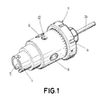
Figure 1 shows a perspective view of the device proposed by the invention. -
Figure 2 shows a cross-section view of the device where its components can be seen, where the pneumatic mechanism can be seen in detail with the piston in the upper position. -
Figure 3 shows a cross-section view of the device with the piston in the lower position. -
Figure 4 shows a plan cross-section view of the device where detail of the pins can be seen. - In view of the drawings described, it can be observed how in one of the possible embodiments of the invention a tool holder device comprising a body (1) and a movable part (2), where the movable part (2) comprises securing means (4) for securing the tool (24), preferably an anchoring clamp which secures the tool (24), which is the object of the vibration of the invention, as can be seen in
Figures 2 ,3 and4 . - The body (1) comprises an anchoring element (5) which is preferably an anchoring cone or a machined shaft for its coupling to a machine, and through which a rotational movement is transmitted to the body (and therefore to the tool) and the compressed air of the machine is transferred to the tool holder device. This compressed air is necessary for the vibratory effect of the tool holder as will be explained below.
- The body (1) comprises a housing inside which the movable part (2) can move axially. The movable part (2) which is preferably a chuck shaft is formed by two parts, a first part (19) which has a conduit (8) through which compressed air enters from inside the anchoring cone and a second part (20) to which there are coupled the anchoring means (4) for anchoring the tool (preferably an anchoring clamp).
- Said first part (19) and second part (20) of the movable part (2) or chuck shaft is preferably fixed by means of tie bolts along the contact area between them, such that the joining of these parts form the movable part (2), as can be seen in
Figures 1 ,2 ,3 and4 . - The movable part (2) comprises a chamber (21) hosting a pneumatic piston (6) which generates the vibratory movement, specifically the second part (20) acts as a sleeve where said pneumatic piston (6) slides in a guided manner.
- The pneumatic piston (6) is the element responsible for generating the axial vibratory movement of the tool holder device, and it comprises distribution holes or inner conduits (22) traversing the pneumatic piston (6) opening into the chamber (21) on axially opposite faces of the pneumatic piston (6) and therefore distribute the compressed air in an alternating manner into the chamber (21) to produce the axial vibratory movement of the pneumatic piston (6).
- The second part (20) comprises conduction means (23) carrying the compressed air from the conduit (8) of the first part (19) to the distribution holes or inner conduits (22) of the piston (6).
- The piston (6) moves by means of the entrance of air through the anchoring cone, where the air is carried through the conduit (8) communicated with the inner conduits (22) traversing the piston (6) which receive the air and are communicated with conduction means (23) receiving the air in an alternating manner, thus allowing the alternating movement of the piston (6).
- The two end positions of the piston (6) in its movement within the chuck shaft are, on one side, the contact position with the first part (1) and on another, the contact position with the inner face of the second part (20) of the chuck shaft, as can be seen in
Figures 2 and3 . - Inside the chamber (21) there is housed a return means (12), which is preferably a spring, aiding the movement of the piston (6), and where the chuck shaft (2) preferably further comprises two holes (17) which are preferably silencing holes, the function of which is to allow the air to exit from the system, as can be seen in
Figures 1 ,2 ,3 and4 . - Antifriction means (16), preferably a bronze bushing, are located in the interface existing between the chuck shaft (2) and the body (1) for guiding the chuck shaft (2), where said bronze bushing is fixed inside the body (1), as can be seen in
Figures 2 ,3 and4 . - To successfully transfer the rotational movement generated on the body (1) to the tool through the chuck shaft (2), attachment means (9), which are preferably three antirotation pins, were placed so that the movable part (2), preferably the chuck shaft, rotates integrally with the body (1), as can be seen in
Figures 1 ,2 ,3 and4 . - Each antirotation pin is preferably made up of two bolts which are anchored to the body (1) such that both the rotational movement and the axial vibratory movement of the piston (6) are transferred to the tool (24) through the chuck shaft (2).
- The tool holder device comprises an axial movement amplitude regulator (7) which is made up of a nut (14) and adjusting means (13) which are preferably studs, it performs the function of fixing the freedom of movement of the chuck shaft (2) inside the body (1), leaving more or less space to perform the vibration with different amplitudes; where the nut (14) acts as a stop to the movement, and the studs are responsible for fixing the nut (14) on the body (1), the space comprised between the chuck shaft (2) and the nut (14) being able to be varied.
- The body (1) has preferably an engraved scribing block on its outer surface indicating the amplitude at all times and facilitating the adjustment in the case of modifying the required amplitude by taking the nut (14) as a reference, as can be seen in
Figures 1 ,2 ,3 and4 . - The type of vibrations of the present invention are considered as low frequency vibrations (between 0 and 5000 Hz) depending on the size of the pneumatic actuator, the tool used, the material to be drilled, etc., the amplitude of the vibrations being able to be regulated, as has been indicated above, by means of the axial movement amplitude regulator (7), adapting the device to the needs of the process itself.
- On the other hand, a first shock-absorbing stop (10) and a second shock-absorbing stop (11), which are preferably rubber stops, are arranged inside the body (1) for minimizing the collision impact between the movable part (2) and the body (1), for which a rubber stop is anchored to the first part (19) of the movable part (2) by fixing means (18), which are preferably two bolts, and another rubber stop is anchored to the second part (20) of the movable part (2) preferably by another two bolts.
- The two rubber stops move integrally with the movable part (2), where said movable part (2) abuts, on one side, with the inner face of the body, and on another side, with the inner face of the amplitude regulator (7), which is that which fixes the clearance between the rubber stop and the amplitude regulator (7).
- In turn, between the anchoring cone and the individual part with the air inlet, there is a sealing element (15), which is preferably a ring joint acting as an air-lock, such that it guides the entry of air to the pneumatic mechanism (3), as can be seen in
Figures 2 ,3 and4 . - Overall, by means of the explanation described herein, a tool holder device which can be coupled to a machine, in which a drilling tool is anchored and which allows obtaining vibratory movements of the latter as it moves forward is made possible through a pneumatic mechanism, where the air enters through coupling to the machine or equipment and causes the movement of a piston which is responsible for providing the tool with an axial vibratory movement with respect to the controlled linear movement of the support, as can be seen in view of
Figures 1 ,2 and3 .
Claims (14)
- Tool holder device which can be coupled to a machine which can rotate the device, the device comprising securing means (4) for securing a tool (24), characterised in that it comprises a movable part (2) which can move in an axial direction and a pneumatic mechanism (3), wherein said pneumatic mechanism (3) can cause an axial vibratory movement of the movable part (2), and in that the securing means (4) are coupled to the movable part (2).
- Tool holder device according to the preceding claim, wherein the pneumatic mechanism (3) comprises a pneumatic piston (6) performing a linear movement in at least two directions.
- Tool holder device according to any of the preceding claims, wherein the movable part (2) comprises a chamber (21) hosting the pneumatic piston (6) such that it can slide axially inside the chamber (21) and conduction means (8, 23) which allow carrying compressed air to inner conduits (22) traversing the piston (6) and opening into the chamber (21) on axially opposite faces of the pneumatic piston (3).
- Tool holder device according to any of the preceding claims, comprising a body (1) which comprises an anchoring element (5) which allows coupling the device to the machine and a housing inside which the movable part (2) can move axially and in that it comprises a conduit communicating a compressed air supply source of the machine with the conduction means (8,23).
- Tool holder device according to any of the preceding claims, comprising a regulator (7) which allows varying the amplitude of the axial movement of the movable part (2).
- Tool holder device according to claim 5, wherein the regulator (7) comprises a nut (14) which is coupled on the body (1) closing the housing in a first direction according to the axial direction to act as a stop to the movement of the movable part (2) in the first direction, whereas the body (1) closes the housing in a second direction according to the axial direction and acts as a stop of the movement and in that the nut (14) can vary its position in the axial direction by varying the axial length of the housing.
- Tool holder device according to any of claims 5 or 6, wherein the regulator (7) comprises adjusting means (13) anchoring the nut (14) to the movable part (2) of the device to fix the position of said nut (14).
- Tool holder device according to any of claims 4 to 7, comprising a first shock-absorbing stop (10) housed inside the housing to absorb the collision impact of the movable part (2) with the body (1).
- Tool holder device according to any of claims 5 to 8, comprising a second shock-absorbing stop (11) in the regulator to absorb the collision impact of the movable part (2) with the regulator (7).
- Tool holder device according to any of claims 4 to 9, comprising attachment means (9) for attaching the movable part (2) to the body (1).
- Tool holder device according to any of the preceding claims, wherein the pneumatic mechanism (3) comprises return means (12).
- Tool holder device according to any of claims 4 to 11, comprising a sealing element (15) between the body (1) and the movable part (2).
- Tool holder device according to any of claims 4 to 12, comprising an antifriction element (16) for the axial guiding between the movable part (2) and the body (1).
- Tool holder device according to any of the preceding claims 4 to 13, wherein the fixed part (1) has silencing through holes (17) made on its surface which allow air to exit the device.
Applications Claiming Priority (1)
| Application Number | Priority Date | Filing Date | Title |
|---|---|---|---|
| PCT/ES2012/070227 WO2013150162A1 (en) | 2012-04-03 | 2012-04-03 | Tool holder device |
Publications (2)
| Publication Number | Publication Date |
|---|---|
| EP2835199A1 true EP2835199A1 (en) | 2015-02-11 |
| EP2835199B1 EP2835199B1 (en) | 2016-05-04 |
Family
ID=46124385
Family Applications (1)
| Application Number | Title | Priority Date | Filing Date |
|---|---|---|---|
| EP12721878.2A Not-in-force EP2835199B1 (en) | 2012-04-03 | 2012-04-03 | Tool holder device |
Country Status (8)
| Country | Link |
|---|---|
| US (1) | US20150023746A1 (en) |
| EP (1) | EP2835199B1 (en) |
| CN (1) | CN104271294B (en) |
| BR (1) | BR112014024808A2 (en) |
| CA (1) | CA2869510A1 (en) |
| ES (1) | ES2584608T3 (en) |
| MX (1) | MX351258B (en) |
| WO (1) | WO2013150162A1 (en) |
Families Citing this family (2)
| Publication number | Priority date | Publication date | Assignee | Title |
|---|---|---|---|---|
| CN106941344A (en) * | 2016-01-05 | 2017-07-11 | 联发科技(新加坡)私人有限公司 | Signal self-calibration circuit and method |
| CN119733859A (en) * | 2024-12-09 | 2025-04-01 | 航工智能装备科技(重庆)有限责任公司 | Auxiliary processing device for regulating and controlling axial movement of main shaft of machine tool |
Family Cites Families (12)
| Publication number | Priority date | Publication date | Assignee | Title |
|---|---|---|---|---|
| US3028771A (en) * | 1958-06-23 | 1962-04-10 | Boyar Schultz Corp | Revolving deep driller |
| US3003372A (en) * | 1959-09-29 | 1961-10-10 | Howard J Findley | Apparatus for cutting material |
| US3608334A (en) * | 1968-07-09 | 1971-09-28 | Richard Glimpel | Device for limiting torque |
| FR2368336A1 (en) * | 1976-10-20 | 1978-05-19 | Irigny Mecanique | Resiliently mounted machine tool cutter holder - has deflection of holder against strong spring measured by dial gauge to determine necessity for tool change |
| SU623658A1 (en) * | 1977-04-01 | 1978-08-09 | Balabanov Nikolaj | Vibrated drilling head |
| US4123188A (en) * | 1977-04-04 | 1978-10-31 | Gardner-Denver Company | Control system for peck drilling tool |
| CH645826A5 (en) * | 1980-07-07 | 1984-10-31 | Ver Pignons Fabriken Ag | Chip breaker for automatic drilling and turning machines |
| FR2765505B1 (en) * | 1997-07-07 | 1999-08-27 | Inst Nat Polytech Grenoble | DRILLING HEAD WITH VIBRATORY EFFECT |
| CN2584328Y (en) * | 2002-12-13 | 2003-11-05 | 天津理工学院 | Vibration bit for deep hole and hardworking material |
| CN1194836C (en) * | 2003-06-18 | 2005-03-30 | 北京航空航天大学 | Vibration equipment for drilling |
| FR2944722B1 (en) * | 2009-04-28 | 2014-10-10 | Arts | AXIAL VIBRATION DRILLING HEAD |
| FR2961729B1 (en) * | 2010-06-25 | 2013-03-29 | Ct Tech De L Ind Du Decolletage | DRILLING HEAD FOR MACHINE TOOL |
-
2012
- 2012-04-03 MX MX2014012029A patent/MX351258B/en active IP Right Grant
- 2012-04-03 CN CN201280072806.0A patent/CN104271294B/en not_active Expired - Fee Related
- 2012-04-03 ES ES12721878.2T patent/ES2584608T3/en active Active
- 2012-04-03 WO PCT/ES2012/070227 patent/WO2013150162A1/en not_active Ceased
- 2012-04-03 EP EP12721878.2A patent/EP2835199B1/en not_active Not-in-force
- 2012-04-03 BR BR112014024808A patent/BR112014024808A2/en not_active Application Discontinuation
- 2012-04-03 CA CA2869510A patent/CA2869510A1/en not_active Abandoned
-
2014
- 2014-10-03 US US14/505,699 patent/US20150023746A1/en not_active Abandoned
Non-Patent Citations (1)
| Title |
|---|
| See references of WO2013150162A1 * |
Also Published As
| Publication number | Publication date |
|---|---|
| CA2869510A1 (en) | 2013-10-10 |
| ES2584608T3 (en) | 2016-09-28 |
| EP2835199B1 (en) | 2016-05-04 |
| MX351258B (en) | 2017-10-06 |
| MX2014012029A (en) | 2014-12-08 |
| CN104271294A (en) | 2015-01-07 |
| CN104271294B (en) | 2016-08-24 |
| BR112014024808A2 (en) | 2017-07-11 |
| WO2013150162A1 (en) | 2013-10-10 |
| US20150023746A1 (en) | 2015-01-22 |
Similar Documents
| Publication | Publication Date | Title |
|---|---|---|
| US11260484B2 (en) | Tool drive having a spindle shaft and operating method | |
| US9981321B2 (en) | Tool, machine tool, and workpiece machining method | |
| CN113814432A (en) | Adjustable stiffness and damping vibration damping boring bar and control method | |
| US7692360B2 (en) | Apparatus for ultrasonic vibration-assisted machining | |
| JP4539499B2 (en) | Vibration processing apparatus and vibration processing method | |
| RU2583109C2 (en) | Pull stud with outer and inner coolant feed and cnc machine using said pull stud | |
| JP6154202B2 (en) | Drilling jig, drilling unit and drilling method | |
| US8430610B2 (en) | Fluttering prevention device for working machine | |
| CN107470995A (en) | A kind of shake table for precision ultrasonic processing | |
| KR101927767B1 (en) | 5-axis machine | |
| CN105612017A (en) | Tool spindle having an active magnetic bearing | |
| EP2835199B1 (en) | Tool holder device | |
| US20160243668A1 (en) | Advancing device for generating a secondary advancing movement of a tool | |
| JP6468788B2 (en) | Deburring device | |
| KR20130069661A (en) | Method for processing an inner face of a housing having an opening | |
| KR20200143603A (en) | Ultrasonic vibration-assisted ultra-slim lathe | |
| WO2019142600A1 (en) | Lathe | |
| US10486236B2 (en) | Tool assembly for a rotating device | |
| JP2009056569A (en) | Vibration cutting device | |
| KR20140143871A (en) | Computer numerical control machine tool | |
| CN106541418A (en) | End effector and industrial robot | |
| JP7287311B2 (en) | Tool guide device | |
| WO2016209145A1 (en) | Orbital machine, method, computer program and a computer program product for using said machine | |
| WO2026038218A9 (en) | A deep boring tool system with a built-in active dynamic absorber, for controlling unwanted machine chatter | |
| US20190070671A1 (en) | Method for machining a workpiece, tool head for a lathe, and lathe |
Legal Events
| Date | Code | Title | Description |
|---|---|---|---|
| PUAI | Public reference made under article 153(3) epc to a published international application that has entered the european phase |
Free format text: ORIGINAL CODE: 0009012 |
|
| 17P | Request for examination filed |
Effective date: 20141016 |
|
| AK | Designated contracting states |
Kind code of ref document: A1 Designated state(s): AL AT BE BG CH CY CZ DE DK EE ES FI FR GB GR HR HU IE IS IT LI LT LU LV MC MK MT NL NO PL PT RO RS SE SI SK SM TR |
|
| AX | Request for extension of the european patent |
Extension state: BA ME |
|
| DAX | Request for extension of the european patent (deleted) | ||
| GRAP | Despatch of communication of intention to grant a patent |
Free format text: ORIGINAL CODE: EPIDOSNIGR1 |
|
| INTG | Intention to grant announced |
Effective date: 20151112 |
|
| GRAS | Grant fee paid |
Free format text: ORIGINAL CODE: EPIDOSNIGR3 |
|
| GRAA | (expected) grant |
Free format text: ORIGINAL CODE: 0009210 |
|
| AK | Designated contracting states |
Kind code of ref document: B1 Designated state(s): AL AT BE BG CH CY CZ DE DK EE ES FI FR GB GR HR HU IE IS IT LI LT LU LV MC MK MT NL NO PL PT RO RS SE SI SK SM TR |
|
| REG | Reference to a national code |
Ref country code: GB Ref legal event code: FG4D |
|
| REG | Reference to a national code |
Ref country code: CH Ref legal event code: EP |
|
| REG | Reference to a national code |
Ref country code: AT Ref legal event code: REF Ref document number: 796454 Country of ref document: AT Kind code of ref document: T Effective date: 20160515 |
|
| REG | Reference to a national code |
Ref country code: IE Ref legal event code: FG4D |
|
| REG | Reference to a national code |
Ref country code: DE Ref legal event code: R096 Ref document number: 602012018058 Country of ref document: DE |
|
| REG | Reference to a national code |
Ref country code: NL Ref legal event code: MP Effective date: 20160504 |
|
| REG | Reference to a national code |
Ref country code: LT Ref legal event code: MG4D |
|
| REG | Reference to a national code |
Ref country code: ES Ref legal event code: FG2A Ref document number: 2584608 Country of ref document: ES Kind code of ref document: T3 Effective date: 20160928 |
|
| PG25 | Lapsed in a contracting state [announced via postgrant information from national office to epo] |
Ref country code: NL Free format text: LAPSE BECAUSE OF FAILURE TO SUBMIT A TRANSLATION OF THE DESCRIPTION OR TO PAY THE FEE WITHIN THE PRESCRIBED TIME-LIMIT Effective date: 20160504 Ref country code: FI Free format text: LAPSE BECAUSE OF FAILURE TO SUBMIT A TRANSLATION OF THE DESCRIPTION OR TO PAY THE FEE WITHIN THE PRESCRIBED TIME-LIMIT Effective date: 20160504 Ref country code: NO Free format text: LAPSE BECAUSE OF FAILURE TO SUBMIT A TRANSLATION OF THE DESCRIPTION OR TO PAY THE FEE WITHIN THE PRESCRIBED TIME-LIMIT Effective date: 20160804 Ref country code: LT Free format text: LAPSE BECAUSE OF FAILURE TO SUBMIT A TRANSLATION OF THE DESCRIPTION OR TO PAY THE FEE WITHIN THE PRESCRIBED TIME-LIMIT Effective date: 20160504 |
|
| REG | Reference to a national code |
Ref country code: AT Ref legal event code: MK05 Ref document number: 796454 Country of ref document: AT Kind code of ref document: T Effective date: 20160504 |
|
| PG25 | Lapsed in a contracting state [announced via postgrant information from national office to epo] |
Ref country code: RS Free format text: LAPSE BECAUSE OF FAILURE TO SUBMIT A TRANSLATION OF THE DESCRIPTION OR TO PAY THE FEE WITHIN THE PRESCRIBED TIME-LIMIT Effective date: 20160504 Ref country code: PT Free format text: LAPSE BECAUSE OF FAILURE TO SUBMIT A TRANSLATION OF THE DESCRIPTION OR TO PAY THE FEE WITHIN THE PRESCRIBED TIME-LIMIT Effective date: 20160905 Ref country code: LV Free format text: LAPSE BECAUSE OF FAILURE TO SUBMIT A TRANSLATION OF THE DESCRIPTION OR TO PAY THE FEE WITHIN THE PRESCRIBED TIME-LIMIT Effective date: 20160504 Ref country code: GR Free format text: LAPSE BECAUSE OF FAILURE TO SUBMIT A TRANSLATION OF THE DESCRIPTION OR TO PAY THE FEE WITHIN THE PRESCRIBED TIME-LIMIT Effective date: 20160805 Ref country code: HR Free format text: LAPSE BECAUSE OF FAILURE TO SUBMIT A TRANSLATION OF THE DESCRIPTION OR TO PAY THE FEE WITHIN THE PRESCRIBED TIME-LIMIT Effective date: 20160504 Ref country code: SE Free format text: LAPSE BECAUSE OF FAILURE TO SUBMIT A TRANSLATION OF THE DESCRIPTION OR TO PAY THE FEE WITHIN THE PRESCRIBED TIME-LIMIT Effective date: 20160504 |
|
| PG25 | Lapsed in a contracting state [announced via postgrant information from national office to epo] |
Ref country code: SK Free format text: LAPSE BECAUSE OF FAILURE TO SUBMIT A TRANSLATION OF THE DESCRIPTION OR TO PAY THE FEE WITHIN THE PRESCRIBED TIME-LIMIT Effective date: 20160504 Ref country code: RO Free format text: LAPSE BECAUSE OF FAILURE TO SUBMIT A TRANSLATION OF THE DESCRIPTION OR TO PAY THE FEE WITHIN THE PRESCRIBED TIME-LIMIT Effective date: 20160504 Ref country code: EE Free format text: LAPSE BECAUSE OF FAILURE TO SUBMIT A TRANSLATION OF THE DESCRIPTION OR TO PAY THE FEE WITHIN THE PRESCRIBED TIME-LIMIT Effective date: 20160504 Ref country code: DK Free format text: LAPSE BECAUSE OF FAILURE TO SUBMIT A TRANSLATION OF THE DESCRIPTION OR TO PAY THE FEE WITHIN THE PRESCRIBED TIME-LIMIT Effective date: 20160504 Ref country code: CZ Free format text: LAPSE BECAUSE OF FAILURE TO SUBMIT A TRANSLATION OF THE DESCRIPTION OR TO PAY THE FEE WITHIN THE PRESCRIBED TIME-LIMIT Effective date: 20160504 |
|
| REG | Reference to a national code |
Ref country code: DE Ref legal event code: R097 Ref document number: 602012018058 Country of ref document: DE |
|
| PG25 | Lapsed in a contracting state [announced via postgrant information from national office to epo] |
Ref country code: BE Free format text: LAPSE BECAUSE OF FAILURE TO SUBMIT A TRANSLATION OF THE DESCRIPTION OR TO PAY THE FEE WITHIN THE PRESCRIBED TIME-LIMIT Effective date: 20160504 Ref country code: SM Free format text: LAPSE BECAUSE OF FAILURE TO SUBMIT A TRANSLATION OF THE DESCRIPTION OR TO PAY THE FEE WITHIN THE PRESCRIBED TIME-LIMIT Effective date: 20160504 Ref country code: PL Free format text: LAPSE BECAUSE OF FAILURE TO SUBMIT A TRANSLATION OF THE DESCRIPTION OR TO PAY THE FEE WITHIN THE PRESCRIBED TIME-LIMIT Effective date: 20160504 Ref country code: AT Free format text: LAPSE BECAUSE OF FAILURE TO SUBMIT A TRANSLATION OF THE DESCRIPTION OR TO PAY THE FEE WITHIN THE PRESCRIBED TIME-LIMIT Effective date: 20160504 |
|
| PLBE | No opposition filed within time limit |
Free format text: ORIGINAL CODE: 0009261 |
|
| STAA | Information on the status of an ep patent application or granted ep patent |
Free format text: STATUS: NO OPPOSITION FILED WITHIN TIME LIMIT |
|
| 26N | No opposition filed |
Effective date: 20170207 |
|
| REG | Reference to a national code |
Ref country code: FR Ref legal event code: PLFP Year of fee payment: 6 |
|
| PG25 | Lapsed in a contracting state [announced via postgrant information from national office to epo] |
Ref country code: SI Free format text: LAPSE BECAUSE OF FAILURE TO SUBMIT A TRANSLATION OF THE DESCRIPTION OR TO PAY THE FEE WITHIN THE PRESCRIBED TIME-LIMIT Effective date: 20160504 |
|
| PG25 | Lapsed in a contracting state [announced via postgrant information from national office to epo] |
Ref country code: MC Free format text: LAPSE BECAUSE OF FAILURE TO SUBMIT A TRANSLATION OF THE DESCRIPTION OR TO PAY THE FEE WITHIN THE PRESCRIBED TIME-LIMIT Effective date: 20160504 |
|
| REG | Reference to a national code |
Ref country code: CH Ref legal event code: PL |
|
| REG | Reference to a national code |
Ref country code: IE Ref legal event code: MM4A |
|
| PG25 | Lapsed in a contracting state [announced via postgrant information from national office to epo] |
Ref country code: LI Free format text: LAPSE BECAUSE OF NON-PAYMENT OF DUE FEES Effective date: 20170430 Ref country code: CH Free format text: LAPSE BECAUSE OF NON-PAYMENT OF DUE FEES Effective date: 20170430 Ref country code: LU Free format text: LAPSE BECAUSE OF NON-PAYMENT OF DUE FEES Effective date: 20170403 |
|
| REG | Reference to a national code |
Ref country code: FR Ref legal event code: PLFP Year of fee payment: 7 |
|
| PG25 | Lapsed in a contracting state [announced via postgrant information from national office to epo] |
Ref country code: IE Free format text: LAPSE BECAUSE OF NON-PAYMENT OF DUE FEES Effective date: 20170403 |
|
| PG25 | Lapsed in a contracting state [announced via postgrant information from national office to epo] |
Ref country code: MT Free format text: LAPSE BECAUSE OF NON-PAYMENT OF DUE FEES Effective date: 20170403 |
|
| PG25 | Lapsed in a contracting state [announced via postgrant information from national office to epo] |
Ref country code: AL Free format text: LAPSE BECAUSE OF FAILURE TO SUBMIT A TRANSLATION OF THE DESCRIPTION OR TO PAY THE FEE WITHIN THE PRESCRIBED TIME-LIMIT Effective date: 20160504 |
|
| PG25 | Lapsed in a contracting state [announced via postgrant information from national office to epo] |
Ref country code: HU Free format text: LAPSE BECAUSE OF FAILURE TO SUBMIT A TRANSLATION OF THE DESCRIPTION OR TO PAY THE FEE WITHIN THE PRESCRIBED TIME-LIMIT; INVALID AB INITIO Effective date: 20120403 |
|
| PGFP | Annual fee paid to national office [announced via postgrant information from national office to epo] |
Ref country code: IT Payment date: 20190423 Year of fee payment: 8 Ref country code: ES Payment date: 20190501 Year of fee payment: 8 Ref country code: DE Payment date: 20190429 Year of fee payment: 8 |
|
| PG25 | Lapsed in a contracting state [announced via postgrant information from national office to epo] |
Ref country code: BG Free format text: LAPSE BECAUSE OF FAILURE TO SUBMIT A TRANSLATION OF THE DESCRIPTION OR TO PAY THE FEE WITHIN THE PRESCRIBED TIME-LIMIT Effective date: 20160504 |
|
| PGFP | Annual fee paid to national office [announced via postgrant information from national office to epo] |
Ref country code: FR Payment date: 20190415 Year of fee payment: 8 |
|
| PG25 | Lapsed in a contracting state [announced via postgrant information from national office to epo] |
Ref country code: CY Free format text: LAPSE BECAUSE OF FAILURE TO SUBMIT A TRANSLATION OF THE DESCRIPTION OR TO PAY THE FEE WITHIN THE PRESCRIBED TIME-LIMIT Effective date: 20160504 |
|
| PGFP | Annual fee paid to national office [announced via postgrant information from national office to epo] |
Ref country code: GB Payment date: 20190429 Year of fee payment: 8 |
|
| PG25 | Lapsed in a contracting state [announced via postgrant information from national office to epo] |
Ref country code: MK Free format text: LAPSE BECAUSE OF FAILURE TO SUBMIT A TRANSLATION OF THE DESCRIPTION OR TO PAY THE FEE WITHIN THE PRESCRIBED TIME-LIMIT Effective date: 20160504 |
|
| PG25 | Lapsed in a contracting state [announced via postgrant information from national office to epo] |
Ref country code: TR Free format text: LAPSE BECAUSE OF FAILURE TO SUBMIT A TRANSLATION OF THE DESCRIPTION OR TO PAY THE FEE WITHIN THE PRESCRIBED TIME-LIMIT Effective date: 20160504 |
|
| PG25 | Lapsed in a contracting state [announced via postgrant information from national office to epo] |
Ref country code: IS Free format text: LAPSE BECAUSE OF FAILURE TO SUBMIT A TRANSLATION OF THE DESCRIPTION OR TO PAY THE FEE WITHIN THE PRESCRIBED TIME-LIMIT Effective date: 20160904 |
|
| REG | Reference to a national code |
Ref country code: DE Ref legal event code: R119 Ref document number: 602012018058 Country of ref document: DE |
|
| PG25 | Lapsed in a contracting state [announced via postgrant information from national office to epo] |
Ref country code: DE Free format text: LAPSE BECAUSE OF NON-PAYMENT OF DUE FEES Effective date: 20201103 Ref country code: FR Free format text: LAPSE BECAUSE OF NON-PAYMENT OF DUE FEES Effective date: 20200430 |
|
| GBPC | Gb: european patent ceased through non-payment of renewal fee |
Effective date: 20200403 |
|
| PG25 | Lapsed in a contracting state [announced via postgrant information from national office to epo] |
Ref country code: GB Free format text: LAPSE BECAUSE OF NON-PAYMENT OF DUE FEES Effective date: 20200403 |
|
| REG | Reference to a national code |
Ref country code: ES Ref legal event code: FD2A Effective date: 20210826 |
|
| PG25 | Lapsed in a contracting state [announced via postgrant information from national office to epo] |
Ref country code: IT Free format text: LAPSE BECAUSE OF NON-PAYMENT OF DUE FEES Effective date: 20200403 |
|
| PG25 | Lapsed in a contracting state [announced via postgrant information from national office to epo] |
Ref country code: ES Free format text: LAPSE BECAUSE OF NON-PAYMENT OF DUE FEES Effective date: 20200404 |