EP2835061A1 - Liquid-containing capsules and tobacco article provided with said capsules - Google Patents
Liquid-containing capsules and tobacco article provided with said capsules Download PDFInfo
- Publication number
- EP2835061A1 EP2835061A1 EP13790801.8A EP13790801A EP2835061A1 EP 2835061 A1 EP2835061 A1 EP 2835061A1 EP 13790801 A EP13790801 A EP 13790801A EP 2835061 A1 EP2835061 A1 EP 2835061A1
- Authority
- EP
- European Patent Office
- Prior art keywords
- capsule
- wall
- end wall
- protrusion
- thin
- Prior art date
- Legal status (The legal status is an assumption and is not a legal conclusion. Google has not performed a legal analysis and makes no representation as to the accuracy of the status listed.)
- Granted
Links
Images









Classifications
-
- A—HUMAN NECESSITIES
- A24—TOBACCO; CIGARS; CIGARETTES; SIMULATED SMOKING DEVICES; SMOKERS' REQUISITES
- A24D—CIGARS; CIGARETTES; TOBACCO SMOKE FILTERS; MOUTHPIECES OF CIGARS OR CIGARETTES; MANUFACTURE OF TOBACCO SMOKE FILTERS OR MOUTHPIECES
- A24D3/00—Tobacco smoke filters, e.g. filter tips or filtering inserts; Filters specially adapted for simulated smoking devices; Mouthpieces of cigars or cigarettes
- A24D3/04—Tobacco smoke filters characterised by their shape or structure
-
- A—HUMAN NECESSITIES
- A24—TOBACCO; CIGARS; CIGARETTES; SIMULATED SMOKING DEVICES; SMOKERS' REQUISITES
- A24D—CIGARS; CIGARETTES; TOBACCO SMOKE FILTERS; MOUTHPIECES OF CIGARS OR CIGARETTES; MANUFACTURE OF TOBACCO SMOKE FILTERS OR MOUTHPIECES
- A24D3/00—Tobacco smoke filters, e.g. filter tips or filtering inserts; Filters specially adapted for simulated smoking devices; Mouthpieces of cigars or cigarettes
- A24D3/06—Use of materials for tobacco smoke filters
- A24D3/061—Use of materials for tobacco smoke filters containing additives entrapped within capsules, sponge-like material or the like, for further release upon smoking
-
- A—HUMAN NECESSITIES
- A24—TOBACCO; CIGARS; CIGARETTES; SIMULATED SMOKING DEVICES; SMOKERS' REQUISITES
- A24D—CIGARS; CIGARETTES; TOBACCO SMOKE FILTERS; MOUTHPIECES OF CIGARS OR CIGARETTES; MANUFACTURE OF TOBACCO SMOKE FILTERS OR MOUTHPIECES
- A24D3/00—Tobacco smoke filters, e.g. filter tips or filtering inserts; Filters specially adapted for simulated smoking devices; Mouthpieces of cigars or cigarettes
- A24D3/02—Manufacture of tobacco smoke filters
- A24D3/0204—Preliminary operations before the filter rod forming process, e.g. crimping, blooming
- A24D3/0212—Applying additives to filter materials
- A24D3/0216—Applying additives to filter materials the additive being in the form of capsules, beads or the like
-
- A—HUMAN NECESSITIES
- A24—TOBACCO; CIGARS; CIGARETTES; SIMULATED SMOKING DEVICES; SMOKERS' REQUISITES
- A24D—CIGARS; CIGARETTES; TOBACCO SMOKE FILTERS; MOUTHPIECES OF CIGARS OR CIGARETTES; MANUFACTURE OF TOBACCO SMOKE FILTERS OR MOUTHPIECES
- A24D3/00—Tobacco smoke filters, e.g. filter tips or filtering inserts; Filters specially adapted for simulated smoking devices; Mouthpieces of cigars or cigarettes
- A24D3/02—Manufacture of tobacco smoke filters
- A24D3/025—Final operations, i.e. after the filter rod forming process
- A24D3/0258—Means for making grooves
-
- A—HUMAN NECESSITIES
- A24—TOBACCO; CIGARS; CIGARETTES; SIMULATED SMOKING DEVICES; SMOKERS' REQUISITES
- A24D—CIGARS; CIGARETTES; TOBACCO SMOKE FILTERS; MOUTHPIECES OF CIGARS OR CIGARETTES; MANUFACTURE OF TOBACCO SMOKE FILTERS OR MOUTHPIECES
- A24D3/00—Tobacco smoke filters, e.g. filter tips or filtering inserts; Filters specially adapted for simulated smoking devices; Mouthpieces of cigars or cigarettes
- A24D3/02—Manufacture of tobacco smoke filters
- A24D3/0275—Manufacture of tobacco smoke filters for filters with special features
- A24D3/0291—Manufacture of tobacco smoke filters for filters with special features for hollow tipped filters, e.g. recess filters
-
- A—HUMAN NECESSITIES
- A24—TOBACCO; CIGARS; CIGARETTES; SIMULATED SMOKING DEVICES; SMOKERS' REQUISITES
- A24D—CIGARS; CIGARETTES; TOBACCO SMOKE FILTERS; MOUTHPIECES OF CIGARS OR CIGARETTES; MANUFACTURE OF TOBACCO SMOKE FILTERS OR MOUTHPIECES
- A24D3/00—Tobacco smoke filters, e.g. filter tips or filtering inserts; Filters specially adapted for simulated smoking devices; Mouthpieces of cigars or cigarettes
- A24D3/04—Tobacco smoke filters characterised by their shape or structure
- A24D3/048—Tobacco smoke filters characterised by their shape or structure containing additives
-
- A—HUMAN NECESSITIES
- A24—TOBACCO; CIGARS; CIGARETTES; SIMULATED SMOKING DEVICES; SMOKERS' REQUISITES
- A24F—SMOKERS' REQUISITES; MATCH BOXES; SIMULATED SMOKING DEVICES
- A24F47/00—Smokers' requisites not otherwise provided for
Definitions
- the present invention relates to a capsule containing a liquid, which is to be incorporated in a smoking article such as a filter cigarette, and a smoking article in which the capsule is incorporated.
- a liquid such as water or an aqueous solution
- a filter of a smoking article such as a filter cigarette
- the capsule is incorporated into the filter in the state containing the liquid, and a user breaks the capsule, prior to smoking of the filter cigarette. Therefore, the liquid is spouted out from the broken capsule, and the spouted liquid soaks into the filter.
- the user adds an external force to the capsule via the filter by pinching the filter between the fingers and breaks the capsule.
- the capsule when the capsule has a cylindrical shape, the capsule can include a plurality of grooves on one end wall thereof, and these grooves extend radially from an axis of the capsule (see FIG. 2 of Patent Document 1).
- the grooves When the capsule is crushed, the grooves are broken, and the liquid in the capsule is spouted through the broken grooves.
- a capsule can include two capsule half bodies, and these capsule half bodies are connected to each other via an annular seal (see FIG. 4C of Patent Document 2). According to the capsule like this, when the capsule is crushed, the annular seal is broken, and the liquid in the capsule is spouted through the broken seal.
- the cooling unit includes the capsule containing a cooling liquid, and a hollow fragile protrusion equipped at the capsule (see FIG. 3 of Patent Document 3).
- the cooling unit like this, when the capsule is crushed, the fragile protrusion section is ruptured, the cooling liquid in the capsule is spouted into the cigarette through the ruptured fragile protrusion section, and the spouted cooling liquid extinguishes the burning cone of the cigarette.
- Patent Document 1 The grooves of Patent Document 1, the annular seal of Patent Document 2 and the fragile protrusion of Patent Document 3 all facilitate breakage of the capsules to some degree.
- An object of the present invention is to provide a capsule containing a liquid in which easiness in breakability is enhanced and a breaking position can be determined, and a smoking article in which the capsule is incorporated.
- a capsule containing a liquid of the present invention comprises an elastically deformable capsule body that has a substantially cylindrical shape, includes an end wall closing a distal end thereof and an open end opening a proximal end thereof, and receive a liquid therein, a thin-walled region formed on the end wall of the capsule body, and the thin-walled region being thinner than thicknesses of the end wall and a circumferential wall of the capsule body, a protrusion integrally protruding from the thin-walled region toward an outside of the capsule body, and a closure wall provided at the open end of the capsule body, the closure wall closing the open end.
- the end wall of the capsule body when the circumferential wall of the capsule body receives an external force and is crushed, the internal pressure of the capsule increases, and therefore, the end wall bulges toward an outside. Such bulging of the end wall pulls the thin-walled region outward in the radial direction of the capsule body with respect to the protrusion. Therefore, in the thin-walled region of the end wall, the specific area adjacent to the root of the protrusion is especially stretched. Therefore, the thickness of the specific area further decreases, and the capsule is broken first in the specific area. Once the thin-walled region is broken in this manner, the liquid in the capsule is spouted from the broken spot of the thin-walled region.
- the capsule has such a size as to be capable of being incorporated into a smoking article such as a filter cigarette, especially into a filter of the smoking article.
- the end wall of the capsule body may have a truncated cone shape or a cup shape.
- the end wall can include a central portion surrounding the protrusion and having a diameter smaller than a diameter of the end wall, and an annular portion connecting the central portion and the circumferential wall of the capsule body, and the thin-walled region is formed in the central portion.
- the central portion may be a concave wall in a spherical shape.
- the thin-walled region may be partially provided in the central portion, and in this case, the thin-walled region may include a plurality of V-shaped grooves extending radially to an outer circumference of the central portion from the protrusion.
- the end wall may be flat, and in this case, the thin-walled region may include a plurality of V-shaped grooves extending radially to an outer circumference of the end wall from the protrusion.
- the capsule body may have an annular extended portion integrally extending from an outer circumferential edge of the end wall, and the extended portion like this and the end wall cooperate with each other to form a distal end portion of the capsule into a concave shape.
- the thin-walled region may include a plurality of V-shaped grooves extending radially to the extended portion from the protrusion, for example.
- the end wall may be a concave wall in a spherical shape, and in this case, the thin-walled region may have an annular shape adjacent to the protrusion and surrounding the protrusion.
- the capsule body may have a plurality of ribs on the circumferential wall, and these ribs are disposed at intervals in a circumferential direction of the capsule body.
- the capsule body has a flange formed on an outer circumference of the open end, and in this case, the closure wall is a seal member in a sheet shape, the closure wall being connected to the flange to close the open end liquid-tightly.
- the present invention provides a smoking article equipped with one of the aforementioned capsules.
- the specific area adjacent to the root of the protrusion is broken first in the thin-walled region of the end wall of the capsule body, and from the broken spot, the liquid in the capsule spouts into the smoking article.
- the aforementioned extended portion and ribs increase the rigidity of the circumferential wall in the capsule body. Therefore, when an external force is applied to the circumferential wall of the capsule body, the end wall is deformed into an elliptical shape, and the deformation of the end wall like this significantly stretches the specific area of the thin-walled region located at the root of the protrusion, and breaks the specific area first.
- the capsule of the present invention is equipped with the combination of the thin-walled region and the protrusion, and therefore, the combination thereof determines the breaking position in the thin-walled region, while enhancing breakage of the thin-walled region, that is, easiness in breakability of the capsule. Further, the smoking article of the present invention can easily and accurately spout the liquid in the capsule into the smoking article.
- the filter cigarette 10 as a smoking article is shown, and a capsule of the present invention is incorporated in the filter cigarette 10.
- the filter cigarette 10 comprises a cigarette 12 and a composite filter 16 that is connected to one end of the cigarette 12 via winding of tip paper 14.
- the composite filter 16 includes filter elements 18 and 20 each in a cylindrical shape, and these filter elements 18 and 20 are separated from each other in an axial direction of the cigarette 12.
- the filter elements 18 and 20 each have a filter material of acetate fibers, paper or the like, for example, and a wrapping material in which the filter material is wrapped.
- the filter element 18 which is positioned at the cigarette 12 side may have particles of activated carbon, an aroma material or the like inside the filter element 18.
- a capsule 22 containing a liquid of the present invention is disposed between the filter elements 18 and 20, and the capsule 22 and the filter elements 18 and 20 are disposed in tubular shaped paper (not illustrated) to form the composite filter 16.
- a user applies an external force F to the capsule 22 from outside of the composite filter 16, prior to smoking the filter cigarette 10 or between puffs.
- the external force easily breaks the capsule 22 in a specific breaking position thereof. Therefore, the liquid in the capsule 22 is spouted toward the filter element 18 from the breaking position, and soaks into the filter element 18.
- a water-soluble component contained in mainstream smoke of the cigarette 12 dissolves in the liquid soaked into the filter element 18, and thereby, the water-soluble component in the mainstream smoke which passes through the filter element 18 is decreased. As a result, flavor and taste of the cigarette 12 change. If an aromatic is contained in the liquid, fragrance and flavor of the aroma material are added to the mainstream smoke.
- FIG. 2 to FIG. 4 show a capsule 22a of embodiment E1.
- the capsule 22a includes a substantially cylindrical capsule body 24, and the capsule body 24 is elastically deformable.
- the capsule body 24 has an end wall 26 and an open end 28, and the end wall 26 closes a distal end of the capsule body 24.
- the capsule body 24 like this is obtained by injection-molding a synthetic resin.
- a synthetic resin for example, as the synthetic resin forming the capsule body 24, low density polyethylene (NOVATEC LD manufactured by Japan Polyethylene Corporation) is usable.
- the capsule 22a has such a size as to be capable of being disposed in a cylindrical cavity which is secured between the filter elements 18 and 20 of the composite filter 16.
- a length along a longitudinal direction of the capsule 22a is preferably shorter than a length along a longitudinal direction of the cavity by approximately 1 to 3 mm
- a maximum outside diameter of the capsule 22a is preferably smaller than an inside diameter of the cavity (diameters of the filter elements 18 and 20) by approximately 0.5 to 2 mm. More specifically, the maximum outside diameter of the capsule 22a is approximately 6 mm.
- the capsule 22a has the aforementioned size with respect to the cavity, not only production of the composite filter 16 which contains the capsule 22 in the cavity is facilitated, but also the user can easily recognize the capsule 22a in the composite filter 16, and further, a position and an orientation of the capsule 22a in the cavity are stabilized.
- the end wall 26 has a truncated cone shape, and includes a central portion 30 and a tapered portion 34.
- the central portion 30 has a diameter smaller than a diameter of the end wall 26, while the tapered portion 34 forms an annular portion which connects the central portion 30 and a circumferential wall 32 of the capsule body 24.
- the central portion 30 has a diameter Dc (see FIG. 4 ) of 2 mm, for example, and a taper angle ⁇ of the tapered portion 34 is 45°, for example.
- an outside diameter, an inside diameter and a wall thickness of the circumferential wall 32 are gradually decreased slightly toward the tapered portion 34 from the open end 28.
- the circumferential wall 32 also forms a taper shape, and the diameter of the end wall 26 is smaller than a diameter of the open end 28, and a thickness of an end of the circumferential wall 32 adjacent to the end wall 26 corresponds to a thickness Tt of the tapered portion 34.
- the thickness Tt is 0.3 mm.
- a thickness Tc of the central portion 30 is smaller than the thickness Tt of the tapered portion 34.
- the thickness Tc is preferably from 0.1 mm to 0.2 mm.
- a whole of the central portion 30 forms a thin-walled region.
- a rod-shaped protrusion 36 is formed in a center of the central portion 30, and the protrusion 36 protrudes toward outside the capsule body 24.
- a diameter Dp and a protrusion length L of the protrusion 36 are respectively 0.4 to 0.5 mm and 0.4 mm, for example.
- the open end 28 of the capsule body 24 has a flange 38 on an outer circumference thereof, and a thickness and an outside diameter of the flange 38 are respectively 0.5 mm and 6.6 mm, for example.
- the open end 28 is liquid-tightly closed by a seal member 40 as a closure wall.
- the seal member 40 is a sheet having flexibility, and is bonded to the flange 38 without inhibiting the elastic deformation of the capsule body 24.
- the seal member 40 is formed by a polyamide/low density polyethylene laminate sheet (NY #15/DL/LC-21, 50 ⁇ m, manufactured by TAMAPOLY CO., LTD.), and is bonded to the flange 38 by a heat seal.
- a contact area (a heat seal area) between the seal member 40 and the flange 38 increases when the seal member 40 is bonded to the flange 38, and therefore, the seal strength of the seal member 40 is increased.
- the capsule body 24 and the seal member 40 described above form the capsule 22a, and the capsule 22a like this contains a liquid inside it.
- a liquid which is contained in the capsule 22a, in addition to distilled water, an aqueous solution in which an additive such as an aroma material is dissolved in the distilled water is conceivable.
- the capsule 22a of embodiment E1 described above contains 130 mg of liquid, for example.
- the capsule 22a When the capsule 22a is disposed in the composite filter 16, the capsule 22a has a posture in which the end wall 26 is oriented to the filter element 18 at the cigarette 12 side, as is obvious from FIG. 1 .
- the user holds the composite filter 16 with the fingers via the tip paper 14 prior to smoking the filter cigarette 10 or between puffs, and the external force F (see FIG. 1 ) can be applied to the capsule 22a in the composite filter 16 from both sides in a diameter direction of the capsule 22a.
- the external force F like this is followed by the elastic deformation of the capsule body 24, and crushes the capsule 22a. As a result, an internal pressure of the capsule 22a is increased.
- the circumferential wall 32 of the capsule body 24 has the flange 38 at the open end 28, and slightly forms the taper shape, and therefore, in the circumferential wall 32, a portion at the end wall 26 side is crushed more easily as compared with a portion at the flange 38 side.
- the increase of the internal pressure in the capsule 22a causes the end wall 26 to bulge toward the outside. That is, the taper portion 34 of the end wall 26 is elastically deformed so as to expand toward the outside. The elastic deformation of the tapered portion 34 pulls the central portion 30 toward the outside in the radial direction with respect to the protrusion 36. Therefore, a specific area adjacent to a root of the protrusion 36 in the central portion 30 is especially stretched, and the thickness of the specific area significantly decreases. As a result, the central portion 30 is broken first in the specific area. In this case, the protrusion 36 becomes a trigger at the time of breaking the specific area of the central portion 30 and has a function of determining the breaking position in the central portion 30 and facilitating breakage of the central portion 30 as a thin-walled region.
- the breaking spot is limited to the specific area adjacent to the protrusion 36. Further abrupt reduction in the internal pressure is sensed by the user through the fingers of the user, and the user can confirm the breakage of the capsule 22a.
- the liquid in the capsule 22a spouts toward the filter element 18 from the breaking spot of the central portion 30, and soaks into the filter element 18.
- the breaking position of the central portion 30 is limited to the specific position adjacent to the root of the protrusion 36, that is, the center of the end wall 26 as described above, the liquid spouted from the capsule 22a soaks into the center of the end surface in the filter element 18, and forms a liquid soaked area LA ( FIG. 1 ) in a central region in the filter element 18. Accordingly the liquid spouted from the capsule 22a does not wet the tubular shaped paper and the tip paper of the composite filter 16.
- the filter cigarette 10 is smoked in a state in which the liquid soaks into the filter element 18, the water-soluble component contained in the mainstream smoke dissolves into the liquid in the filter element 18, and therefore, the water-soluble component in the mainstream smoke passing through the filter element 18 decreases, whereby the flavor and the taste of the mainstream smoke change.
- an aroma material is contained in the liquid, the fragrance and flavor of the aroma material are added to the mainstream smoke, and the user also can enjoy the fragrance and the flavor of the aroma material at the same time.
- the present invention is not limited to the capsule 22a of embodiment E1 described above.
- FIG. 5 to FIG. 8 respectively show modifications of the capsule 22a of embodiment E1. Capsules 22a 1 to 22a 4 of these modifications differ in the following points when compared with the capsule 22a of embodiment E1 or the capsule of the modification already described.
- the capsule 22a 1 in FIG. 5 differs from the capsule 22a in a point that a protrusion length L1 of the protrusion 36 is increased to 1.0 mm.
- the capsule 22a 2 in FIG. 6 differs from the capsule 22a 1 in a point that the end wall 26 has a cup shape.
- the capsule 22a 3 in FIG. 7 differs from the capsule 22a in a point that a diameter Dc1 of the central portion 30 is increased to 3 mm.
- the capsule 22a 4 in FIG. 8 differs from the capsule 22a 3 in a point that the protrusion length L1 of the protrusion 36 is increased to 1.0 mm.
- the capsule 22a 1 to 22a 4 have similar advantages to the advantage of the capsule 22a of embodiment E1.
- FIG. 9 to FIG. 11 respectively show a capsule 22b of embodiment E2 and a part of the capsule 22b.
- the capsule 22b differs from a group of the capsule 22a of embodiment E1 only in the shape of the central portion 30.
- a central portion 42 has a plurality of V-shaped grooves 44 as a thin-walled region, while having a thickness Tc1 substantially the same as a thickness of the other region of the capsule body 24.
- the V-shaped grooves 44 are disposed radially on an outer surface of the central portion 42 with the protrusion 36 as a center, and extend to an outer circumference of the central portion 42 from the root of the protrusion 36.
- a V-shape angle ⁇ of each of the V-shaped grooves 44 is 90°, for example, and a thickness Tc2 of a bottom of the V-shaped groove 44 is 0.17 mm, for example.
- the tapered portion 34 of the end wall 26 is expanded by elastic deformation as described above. Therefore, the bottom of each of the V-shaped grooves 44 is pulled outward in the radial direction of the end wall 26 with respect to the protrusion 36, the bottom is especially stretched at a specific area adjacent to the root of the protrusion 36, and the thickness of the bottom is reduced. As a result, the bottom of any of the V-shaped grooves 44 is broken first in the specific area, and from the breaking spot, the liquid in the capsule 22b is spouted.
- FIG. 12 and FIG. 13 show a capsule 22c of embodiment E3.
- a capsule 22c differs from the capsule 22a only in the shape of the central portion 30 of the end wall 26.
- a central portion 46 of the capsule 22c is not flat, but is formed as a concave wall in a spherical shape which is recessed toward the inside of the capsule body 24, and has the diameter Dc and the wall thickness Tc.
- the central portion 46 is pulled outward in the radial direction from the protrusion 36 when the external force F is applied to the capsule 22c, and the central portion 46 is broken first in a specific area adjacent to the protrusion 36.
- FIG. 14 to FIG. 17 respectively show a capsule 22d of embodiment E4 and a part thereof.
- the capsule 22d differs in the following point.
- the end wall 26 of the capsule 22d does not have the tapered portion 34, and a whole of the end wall 26 is formed as a flat wall. Further, in the case of the capsule 22d, the V-shaped groove 44 extends to the outer circumference of the end wall 26 from the protrusion 36, and has a bottom of a thickness Tc3.
- the thickness Tc3 is a value between Tc (0.12 mm) and Tc2 (0.17 mm), for example, 0.13 mm.
- a plurality of thin ribs 48 are formed on an inner circumferential surface of the capsule body 24 as is obvious from FIG. 16 .
- These ribs 48 are disposed at equal intervals in a circumferential direction of the capsule body 24, and extend in an axial direction of the capsule body 24 to the open end 28 from the end wall 26.
- a thickness of the rib 48 is 0.2 mm.
- a bottom of any of the V-shaped grooves 44 is broken first in a specific area adjacent to the root of the protrusion 36 when the external force F is applied to the capsule 22d.
- FIG. 18 to FIG. 20 show a capsule 22e of embodiment E5.
- the end wall 26 of the capsule body 24 is also formed as a recessed wall, and has an annular flat outer circumferential portion 70, and a central portion 72 which is recessed more than the outer circumferential portion 70, and the central portion 72 is formed as a spherical wall similarly to the central portion 46 of the aforementioned capsule 22c.
- the central portion 72 includes the protrusion 36 in a center thereof and an annular region 74 as a thin-walled region.
- the annular region 74 is adjacent to the root of the protrusion 36, surrounds the protrusion 36, and has the aforementioned thickness Tc.
- a thickness of the central portion 72 gradually increases as it is closer to the outer circumferential portion 70 from the annular region 74, and as shown in FIG. 19 , an outer periphery of the central portion 72 connects to a corner edge at an inner side of an inner circumferential surface in the outer circumferential portion 70.
- a distal end surface of the protrusion 36 and an outer end surface of the outer circumferential portion 70 are located on the same virtual plane.
- FIG. 21 to FIG. 23 show a capsule 22f of embodiment E6.
- the end wall 26 of the capsule body 24 is formed as a concave wall, and the outer circumferential portion 70 of the end wall 26 forms an extended portion of the circumferential wall 32.
- a central portion 74 of the end wall 26 has a female conical shape, and is slightly recessed toward the inside of the capsule body 24.
- a plurality of V-shaped grooves 44 are formed as thin-walled regions similarly to the capsule 22b in FIG. 9 . These V-shaped grooves 44 are disposed at equal intervals in the circumferential direction of the capsule body 24, and extend radially to the outer circumferential portion 70 from the protrusion 36. Note that in FIG. 22 , only one of the V-shaped grooves 44 is shown.
- ribs 76 are integrally formed on the circumferential wall 32 of the capsule body 24. These ribs 76 extend in the axial direction of the capsule body 24 to the flange 38 from a distal end of the outer circumferential portion 70, and are disposed at equal intervals in the circumferential direction of the capsule body 24.
- a width of the aforementioned rib 76 is not constant along the axial direction of the capsule body 24, and is gradually decreased toward the distal end of the outer circumferential portion 70 from the flange 38 as is obvious from FIG. 23 .
- FIG. 24 shows breaking loads (average values and standard deviations (S. D.)) of the capsules 22a to 22f of embodiments E1 to E6 respectively.
- the result of FIG. 24 is obtained by measuring the breaking loads at the point of time when the external force F is applied to the capsules 22a to 22f, and the central portions 30 and 46, or V-shaped grooves 44 of these capsules are broken at the aforementioned specific areas. Further, FIG. 24 also shows the measurement result of the breaking loads of the capsules in comparative examples C1 to C4 in combination.
- Each of the capsules is filled with a liquid (distilled water) which occupies 94% of a capacity of the capsule, and in measurement of the breaking load, a creep meter (RHEOMETER II, manufactured by YAMADEN co., ltd.) is used.
- a creep meter RHEOMETER II, manufactured by YAMADEN co., ltd.
- the capsules of comparative examples C1 to C4 basically have structures similar to those of the capsules 22a to 22d of embodiments E1 to E4, but differ in the following point.
- FIG. 25 and FIG. 26 show a capsule of comparative example C1.
- the capsule of comparative example C1 has a capsule body which has a substantially hexagonal shape and is slightly tapered, and an end wall 50 in a shape of a flat hexagonal pyramid.
- each ridge of the end wall 50 has V-shaped grooves 52a and 52b respectively on outer and inner sides of the ridge , and the V-shaped grooves 52a and 52b form a thin-walled region that extends along the ridge. Therefore, a thickness of a bottom of the V-shaped grooves 52a and 52b is smaller than a thickness (for example, 0.45 mm) of the ridge, and is 0.12 mm, for example.
- any of the V-shaped grooves 52 of the end wall 50 is firstly broken in a bottom thereof when the aforementioned external force F is applied to the capsule.
- FIG. 27 and FIG. 28 show a capsule of comparative example C2.
- the capsule of comparative example C2 differs from the capsule of comparative example C1 in a point that the capsule of comparative example C2 includes an end wall 54 having a shape of a flat truncated hexagonal pyramid, and on each of ridges of the end wall 54, and a V-shaped groove 56 similar to the V-shaped grooves 52a and 52b is formed only on an inner side of the ridge, respectively.
- any of the V-shaped grooves 56 of the end wall 54 is firstly broken in a bottom thereof, when the aforementioned external force F is applied to the capsule.
- FIG. 29 and FIG. 30 show a capsule of comparative example C3.
- the capsule of comparative example C3 is of the same type as the capsule of Patent Document 1 described above, and includes a cylindrical capsule body, a flat end wall 58, and a plurality of V-shaped grooves 60 as thin-walled regions which are formed on only an inner surface of the end wall 58. These V-shaped grooves 60 are radially distributed with a central portion of the end wall 58 left. Note that a thickness of a bottom of the V-shaped groove 60 is 0.13 mm.
- a capsule of comparative example C4 differs from the capsule 22a only a point that the capsule of comparative example C4 does not have the protrusion 36, when the capsule is compared with the capsule 22a of embodiment E1.
- the capsules of comparative examples C1 to C4 do not have the protrusions 36 which the capsules 22a to 22d of embodiments E1 to E4 have. Therefore, in the case of the capsules of comparative examples C1 to C4, the breaking position in the end wall cannot be determined. Further, the breaking loads of the capsules of embodiments E1 to E6 are smaller than the breaking loads of the capsules of comparative examples C2, C3 and C4. This shows that the protrusion 36 not only determines the breaking position in the end wall, but also contributes to reduction of the breaking load.
- the end wall 26 has the annular outer circumferential portion 70 which protrudes outward from the central portion 72 in addition to the protrusion 36.
- the outer circumferential portion 70 like this increases rigidity of the end wall 26. Therefore, in the case of the capsules 22e and 22f, the end wall 26 is deformed into an elliptical shape when the external force F applied to the capsule body 24 is transmitted to the end wall 26, and the central portion 72 is significantly pulled especially along a longitudinal axis of the ellipse.
- the thin-walled regions (the annular region 74 and the V-shaped grooves 44) of the end wall 26 are easily broken at the root of the protrusion 36. Accordingly, as is obvious from FIG. 24 , the capsules 22e and 22f of embodiments E5 and E6 have the breaking loads smaller than the breaking loads of the capsules 22a to 22d of embodiments E1 to E4. The breaking loads of the capsules 22e and 22f are about the same as the breaking load of the seamless capsule incorporated in a commercially available filter cigarette.
- the breaking loads of the capsule 22c were 64.4 N, 70.1 N, and 95.0 N respectively.
- the breaking load of the capsule varies in accordance with the filling rate of the liquid contained in the capsule, and as the filling rate of the liquid is higher, the breaking load of the capsule decreases. Therefore, as long as a hindrance does not occur to manufacture of a capsule, a higher filling rate of the liquid into the capsule is desirable.
- FIG. 31 to FIG. 33 relate to the capsule 22a, the capsule 22e and the capsule 22f, and show relations between loads repeatedly applied to the capsule bodies of the capsules and distortions of the end walls in the capsule bodies. As is obvious when FIG. 31 to FIG. 33 are compared, it is found that the capsules 22e and 22f are distorted significantly with small loads as compared with the capsule 22a.
- the ribs 76 of the capsule 22f increase rigidity of the circumferential wall 32 more than the rigidity of the circumferential wall 32 of the capsule 22e.
- the central portion 72 has the female conical shape, and therefore, the external force F transmitted to the end wall 26 effectively concentrates on the root of the protrusion 36.
- the breaking load of the capsule 22f becomes smaller than the breaking load of the capsule 22e. Therefore, the capsule 22e may also have the ribs 76.
- the outer circumferential portion 70 effectively works in inhibiting an undesired external force from being directly applied to the protrusion 36. Therefore, the possibility of the capsules 22e and 22f being undesirably broken can be decreased at the time of manufacture of filter cigarettes.
- the capsule body 24 and the seal member 40 as a closure wall are both formed from low density polyethylene
- the capsule body and the closure wall of the present invention can be also formed by a synthetic resin other than low density polyethylene, and are further formable from materials other than synthetic resins.
- the capsule body 24 of the capsule 22a has a tapered shape in which the end wall 26 side has a small diameter
- the capsule body of the present invention may be in a straight cylindrical shape, or a tapered shape in which the open end side has a small diameter.
- the end wall of the capsule body of the present invention is not limited to the truncated conical shape, the cup shape, a flat shape, a concave shape, or the like illustrated in the aforementioned embodiment, and further, the central portion of the end wall is not limited to the flat wall or the spherical wall as illustrated, either.
- the entire region of the end wall of the capsule body may form the thin-walled region, and the groove as the thin-walled region can have a shape other than the V-shape. Further, disposition of the groove is not limited to the radial shape, either.
- the thickness of the thin-walled region is preferably from 0.12 mm to 0.17 mm in the range illustrated with respect to the capsule 22a, on the condition that the thickness of the thin-walled region is smaller than the thicknesses of the end wall and the circumferential wall of the capsule body.
- the capsule body 24 of the capsule 22d has the plurality of ribs 48 on the inner circumferential surface thereof, whereas the capsule body 24 of the capsule 22f has the plurality of ribs 76 on the outer circumferential surface thereof.
- These ribs 48 and 76 are also similarly applicable to the capsules of the other embodiments and the modifications described above.
- the central portion 72 of the end wall 26 may be a flat wall, and the annular outer circumferential portion 70 (the extended portion of the circumferential wall 32) is also applicable to the capsules of the other embodiments and the modifications.
- the capsule of the present invention includes the basic structure constituted of the capsule body, the thin-walled region, the protrusion and the closure wall, the other components (the shapes, disposition and the like) which the capsules of the respective embodiments have are applicable by being optionally combined with the capsules of the other embodiments.
- the capsule of the present invention can be not only incorporated into the filter of a filter cigarette, but also incorporated similarly into various smoking articles equipped with filters.
Landscapes
- Chemical & Material Sciences (AREA)
- Engineering & Computer Science (AREA)
- Materials Engineering (AREA)
- Cigarettes, Filters, And Manufacturing Of Filters (AREA)
- Manufacturing Of Micro-Capsules (AREA)
- Medical Preparation Storing Or Oral Administration Devices (AREA)
- Pens And Brushes (AREA)
- Thermotherapy And Cooling Therapy Devices (AREA)
Abstract
Description
- The present invention relates to a capsule containing a liquid, which is to be incorporated in a smoking article such as a filter cigarette, and a smoking article in which the capsule is incorporated.
- If a liquid such as water or an aqueous solution is soaked into a filter of a smoking article such as a filter cigarette, not only are the characteristics of the flavor and taste of the mainstream smoke generated from the cigarette improved, but also a flavor or taste different from the original flavor or taste of the mainstream smoke can be added to the mainstream smoke, at the time of smoking. In this case, the capsule is incorporated into the filter in the state containing the liquid, and a user breaks the capsule, prior to smoking of the filter cigarette. Therefore, the liquid is spouted out from the broken capsule, and the spouted liquid soaks into the filter. For example, the user adds an external force to the capsule via the filter by pinching the filter between the fingers and breaks the capsule.
- For example, when the capsule has a cylindrical shape, the capsule can include a plurality of grooves on one end wall thereof, and these grooves extend radially from an axis of the capsule (see
FIG. 2 of Patent Document 1). When the capsule is crushed, the grooves are broken, and the liquid in the capsule is spouted through the broken grooves. - Further, a capsule can include two capsule half bodies, and these capsule half bodies are connected to each other via an annular seal (see
FIG. 4C of Patent Document 2). According to the capsule like this, when the capsule is crushed, the annular seal is broken, and the liquid in the capsule is spouted through the broken seal. - Furthermore, there is known a cooling unit for a cigarette, and the cooling unit includes the capsule containing a cooling liquid, and a hollow fragile protrusion equipped at the capsule (see
FIG. 3 of Patent Document 3). According to the cooling unit like this, when the capsule is crushed, the fragile protrusion section is ruptured, the cooling liquid in the capsule is spouted into the cigarette through the ruptured fragile protrusion section, and the spouted cooling liquid extinguishes the burning cone of the cigarette. -
- Patent Document 1: Japanese Patent No.
2515794 - Patent Document 2: Japanese Unexamined Patent Application No.
2008-528053 - Patent Document 3: Japanese Unexamined Patent Application No.
2005-318806 - The grooves of
Patent Document 1, the annular seal ofPatent Document 2 and the fragile protrusion ofPatent Document 3 all facilitate breakage of the capsules to some degree. However, breakage of the grooves and the annular seal, and rupture of the fragile protrusion still require considerable forces, and further easiness in breakability of the capsules is required. - Further, even if the grooves, the seal and the fragile protrusion are broken or ruptured, the spots of breakage or rupture are not unambiguously uniquely determined in the grooves, the seal and the fragile protrusion. Therefore, there is the fear that even when the liquid or the cooling liquid is spouted from the capsule, the spouted liquid or cooling liquid does not effectively soak into the filter or the cigarette.
- An object of the present invention is to provide a capsule containing a liquid in which easiness in breakability is enhanced and a breaking position can be determined, and a smoking article in which the capsule is incorporated.
- The aforementioned object is achieved by a capsule containing a liquid of the present invention, and the capsule comprises an elastically deformable capsule body that has a substantially cylindrical shape, includes an end wall closing a distal end thereof and an open end opening a proximal end thereof, and receive a liquid therein, a thin-walled region formed on the end wall of the capsule body, and the thin-walled region being thinner than thicknesses of the end wall and a circumferential wall of the capsule body, a protrusion integrally protruding from the thin-walled region toward an outside of the capsule body, and a closure wall provided at the open end of the capsule body, the closure wall closing the open end.
- According to the aforementioned capsule, when the circumferential wall of the capsule body receives an external force and is crushed, the internal pressure of the capsule increases, and therefore, the end wall bulges toward an outside. Such bulging of the end wall pulls the thin-walled region outward in the radial direction of the capsule body with respect to the protrusion. Therefore, in the thin-walled region of the end wall, the specific area adjacent to the root of the protrusion is especially stretched. Therefore, the thickness of the specific area further decreases, and the capsule is broken first in the specific area. Once the thin-walled region is broken in this manner, the liquid in the capsule is spouted from the broken spot of the thin-walled region.
- The capsule has such a size as to be capable of being incorporated into a smoking article such as a filter cigarette, especially into a filter of the smoking article.
- The end wall of the capsule body may have a truncated cone shape or a cup shape. In this case, the end wall can include a central portion surrounding the protrusion and having a diameter smaller than a diameter of the end wall, and an annular portion connecting the central portion and the circumferential wall of the capsule body, and the thin-walled region is formed in the central portion. For example, the central portion may be a concave wall in a spherical shape.
- Furthermore, the thin-walled region may be partially provided in the central portion, and in this case, the thin-walled region may include a plurality of V-shaped grooves extending radially to an outer circumference of the central portion from the protrusion.
- Meanwhile, the end wall may be flat, and in this case, the thin-walled region may include a plurality of V-shaped grooves extending radially to an outer circumference of the end wall from the protrusion.
- Whichever shape among the above described shapes the thin-walled region is in, bulging of the end wall especially stretches the specific area of the thin-walled region adjacent to the root of the protrusion when an external force is applied to the capsule, and as a result, the thin-walled region is broken first in the specific area.
- Meanwhile, the capsule body may have an annular extended portion integrally extending from an outer circumferential edge of the end wall, and the extended portion like this and the end wall cooperate with each other to form a distal end portion of the capsule into a concave shape. In this case, the thin-walled region may include a plurality of V-shaped grooves extending radially to the extended portion from the protrusion, for example.
- Furthermore, the end wall may be a concave wall in a spherical shape, and in this case, the thin-walled region may have an annular shape adjacent to the protrusion and surrounding the protrusion. Further, the capsule body may have a plurality of ribs on the circumferential wall, and these ribs are disposed at intervals in a circumferential direction of the capsule body.
- Furthermore, the capsule body has a flange formed on an outer circumference of the open end, and in this case, the closure wall is a seal member in a sheet shape, the closure wall being connected to the flange to close the open end liquid-tightly.
- Further, the present invention provides a smoking article equipped with one of the aforementioned capsules.
- According to the aforementioned smoking article, when the user applies an external force from outside the smoking article to crush the capsule body of the capsule, the specific area adjacent to the root of the protrusion is broken first in the thin-walled region of the end wall of the capsule body, and from the broken spot, the liquid in the capsule spouts into the smoking article.
- Further, the aforementioned extended portion and ribs increase the rigidity of the circumferential wall in the capsule body. Therefore, when an external force is applied to the circumferential wall of the capsule body, the end wall is deformed into an elliptical shape, and the deformation of the end wall like this significantly stretches the specific area of the thin-walled region located at the root of the protrusion, and breaks the specific area first.
- The capsule of the present invention is equipped with the combination of the thin-walled region and the protrusion, and therefore, the combination thereof determines the breaking position in the thin-walled region, while enhancing breakage of the thin-walled region, that is, easiness in breakability of the capsule. Further, the smoking article of the present invention can easily and accurately spout the liquid in the capsule into the smoking article.
-
-
FIG. 1 is a sectional view showing a filter cigarette in which a capsule is incorporated, as a smoking article. -
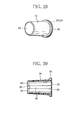
FIG. 2 is a perspective view showing a capsule of embodiment E1. -
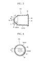
FIG. 3 is a vertical sectional view of the capsule inFIG. 2 . -
FIG. 4 is an end view of the capsule inFIG. 2 seen from an end wall side. -
FIG. 5 is a side view of a capsule which is one of modifications of embodiment E1. -
FIG. 6 is a side view of a capsule which is one of the modifications of embodiment E1. -
FIG. 7 is a side view of a capsule which is one of the modifications of embodiment E1. -
FIG. 8 is a side view of a capsule which is one of the modifications of embodiment E1. -
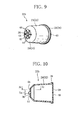
FIG. 9 is a perspective view showing a capsule of embodiment E2. -
FIG. 10 is a vertical sectional view of the capsule inFIG. 9 . -
FIG. 11 is a sectional view taken along line XI-XI inFIG. 10 . -
FIG. 12 is a perspective view showing a capsule of embodiment E3. -
FIG. 13 is a vertical sectional view of the capsule inFIG. 12 . -
FIG. 14 is a perspective view showing a capsule of embodiment E4. -
FIG. 15 is a vertical sectional view of the capsule inFIG. 14 . -
FIG. 16 is a perspective view of a capsule body inFIG. 14 . -
FIG. 17 is a sectional view taken along line XVII-XVII inFIG. 15 . -
FIG. 18 is a perspective view showing a capsule of embodiment E5. -
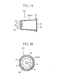
FIG. 19 is a vertical sectional view of the capsule inFIG. 18 . -
FIG. 20 is an end view of the capsule inFIG. 18 seen from a distal end side thereof. -
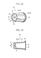
FIG. 21 is a perspective view showing a capsule of embodiment E6. -
FIG. 22 is a vertical sectional view of the capsule inFIG. 21 . -
FIG. 23 is an end view of the capsule inFIG. 21 seen from a distal end side thereof. -
FIG. 24 is a graph showing a breaking load of capsules of embodiments E1 to E6 and comparative examples C1 to C4. -
FIG. 25 is a perspective view of a capsule of comparative example C1. -
FIG. 26 is a vertical sectional view of the capsule inFIG. 25 . -
FIG. 27 is a perspective view of a capsule of comparative example C2. -
FIG. 28 is a vertical sectional view of the capsule inFIG. 27 . -
FIG. 29 is a perspective view of a capsule of comparative example C3. -
FIG. 30 is a vertical sectional view of the capsule inFIG. 29 . -
FIG. 31 is a graph relating to the capsule inFIG. 2 and showing a relation of a load and a distortion. -
FIG. 32 is a graph relating to the capsule inFIG. 18 and showing a relation of a load and a distortion. -
FIG. 33 is a graph relating to the capsule inFIG. 21 and showing a relation of a load and a distortion. - Referring to
FIG. 1 , afilter cigarette 10 as a smoking article is shown, and a capsule of the present invention is incorporated in thefilter cigarette 10. In this case, thefilter cigarette 10 comprises acigarette 12 and acomposite filter 16 that is connected to one end of thecigarette 12 via winding oftip paper 14. - For example, the
composite filter 16 includesfilter elements filter elements cigarette 12. Thefilter elements filter element 18 which is positioned at thecigarette 12 side may have particles of activated carbon, an aroma material or the like inside thefilter element 18. - A
capsule 22 containing a liquid of the present invention is disposed between thefilter elements capsule 22 and thefilter elements composite filter 16. - According to the
aforementioned filter cigarette 10, a user applies an external force F to thecapsule 22 from outside of thecomposite filter 16, prior to smoking thefilter cigarette 10 or between puffs. As will be clear from the explanation that will be described later, the external force easily breaks thecapsule 22 in a specific breaking position thereof. Therefore, the liquid in thecapsule 22 is spouted toward thefilter element 18 from the breaking position, and soaks into thefilter element 18. - A water-soluble component contained in mainstream smoke of the
cigarette 12 dissolves in the liquid soaked into thefilter element 18, and thereby, the water-soluble component in the mainstream smoke which passes through thefilter element 18 is decreased. As a result, flavor and taste of thecigarette 12 change. If an aromatic is contained in the liquid, fragrance and flavor of the aroma material are added to the mainstream smoke. - As the
capsule 22 of the present invention described above, various shapes are conceivable, and specific embodiments of thecapsule 22 will be described hereinafter. -
FIG. 2 to FIG. 4 show acapsule 22a of embodiment E1. Thecapsule 22a includes a substantiallycylindrical capsule body 24, and thecapsule body 24 is elastically deformable. Thecapsule body 24 has anend wall 26 and anopen end 28, and theend wall 26 closes a distal end of thecapsule body 24. Thecapsule body 24 like this is obtained by injection-molding a synthetic resin. For example, as the synthetic resin forming thecapsule body 24, low density polyethylene (NOVATEC LD manufactured by Japan Polyethylene Corporation) is usable. - As is obvious from
FIG. 1 , thecapsule 22a has such a size as to be capable of being disposed in a cylindrical cavity which is secured between thefilter elements composite filter 16. For example, a length along a longitudinal direction of thecapsule 22a is preferably shorter than a length along a longitudinal direction of the cavity by approximately 1 to 3 mm, and a maximum outside diameter of thecapsule 22a is preferably smaller than an inside diameter of the cavity (diameters of thefilter elements 18 and 20) by approximately 0.5 to 2 mm. More specifically, the maximum outside diameter of thecapsule 22a is approximately 6 mm. - If the
capsule 22a has the aforementioned size with respect to the cavity, not only production of thecomposite filter 16 which contains thecapsule 22 in the cavity is facilitated, but also the user can easily recognize thecapsule 22a in thecomposite filter 16, and further, a position and an orientation of thecapsule 22a in the cavity are stabilized. - In the case of embodiment E1, as is clear from
FIG. 2 andFIG. 3 , theend wall 26 has a truncated cone shape, and includes acentral portion 30 and a taperedportion 34. Thecentral portion 30 has a diameter smaller than a diameter of theend wall 26, while the taperedportion 34 forms an annular portion which connects thecentral portion 30 and acircumferential wall 32 of thecapsule body 24. Thecentral portion 30 has a diameter Dc (seeFIG. 4 ) of 2 mm, for example, and a taper angle α of the taperedportion 34 is 45°, for example. In addition, an outside diameter, an inside diameter and a wall thickness of thecircumferential wall 32 are gradually decreased slightly toward the taperedportion 34 from theopen end 28. Therefore, strictly speaking, thecircumferential wall 32 also forms a taper shape, and the diameter of theend wall 26 is smaller than a diameter of theopen end 28, and a thickness of an end of thecircumferential wall 32 adjacent to theend wall 26 corresponds to a thickness Tt of the taperedportion 34. For example, the thickness Tt is 0.3 mm. - A thickness Tc of the
central portion 30 is smaller than the thickness Tt of the taperedportion 34. For example, the thickness Tc is preferably from 0.1 mm to 0.2 mm. In the case of embodiment E1, a whole of thecentral portion 30 forms a thin-walled region. Further, a rod-shapedprotrusion 36 is formed in a center of thecentral portion 30, and theprotrusion 36 protrudes toward outside thecapsule body 24. A diameter Dp and a protrusion length L of theprotrusion 36 are respectively 0.4 to 0.5 mm and 0.4 mm, for example. - The
open end 28 of thecapsule body 24 has aflange 38 on an outer circumference thereof, and a thickness and an outside diameter of theflange 38 are respectively 0.5 mm and 6.6 mm, for example. Theopen end 28 is liquid-tightly closed by aseal member 40 as a closure wall. Theseal member 40 is a sheet having flexibility, and is bonded to theflange 38 without inhibiting the elastic deformation of thecapsule body 24. - For example, the
seal member 40 is formed by a polyamide/low density polyethylene laminate sheet (NY #15/DL/LC-21, 50µm, manufactured by TAMAPOLY CO., LTD.), and is bonded to theflange 38 by a heat seal. As compared with the case in which theseal member 40 is directly bonded to theopen end 28, a contact area (a heat seal area) between theseal member 40 and theflange 38 increases when theseal member 40 is bonded to theflange 38, and therefore, the seal strength of theseal member 40 is increased. - The
capsule body 24 and theseal member 40 described above form thecapsule 22a, and thecapsule 22a like this contains a liquid inside it. For example, as the liquid which is contained in thecapsule 22a, in addition to distilled water, an aqueous solution in which an additive such as an aroma material is dissolved in the distilled water is conceivable. - The
capsule 22a of embodiment E1 described above contains 130 mg of liquid, for example. When thecapsule 22a is disposed in thecomposite filter 16, thecapsule 22a has a posture in which theend wall 26 is oriented to thefilter element 18 at thecigarette 12 side, as is obvious fromFIG. 1 . - According to the
filter cigarette 10 in which thecapsule 22a is incorporated, the user holds thecomposite filter 16 with the fingers via thetip paper 14 prior to smoking thefilter cigarette 10 or between puffs, and the external force F (seeFIG. 1 ) can be applied to thecapsule 22a in thecomposite filter 16 from both sides in a diameter direction of thecapsule 22a. The external force F like this is followed by the elastic deformation of thecapsule body 24, and crushes thecapsule 22a. As a result, an internal pressure of thecapsule 22a is increased. - As described above, the
circumferential wall 32 of thecapsule body 24 has theflange 38 at theopen end 28, and slightly forms the taper shape, and therefore, in thecircumferential wall 32, a portion at theend wall 26 side is crushed more easily as compared with a portion at theflange 38 side. - Therefore, the increase of the internal pressure in the
capsule 22a causes theend wall 26 to bulge toward the outside. That is, thetaper portion 34 of theend wall 26 is elastically deformed so as to expand toward the outside. The elastic deformation of the taperedportion 34 pulls thecentral portion 30 toward the outside in the radial direction with respect to theprotrusion 36. Therefore, a specific area adjacent to a root of theprotrusion 36 in thecentral portion 30 is especially stretched, and the thickness of the specific area significantly decreases. As a result, thecentral portion 30 is broken first in the specific area. In this case, theprotrusion 36 becomes a trigger at the time of breaking the specific area of thecentral portion 30 and has a function of determining the breaking position in thecentral portion 30 and facilitating breakage of thecentral portion 30 as a thin-walled region. - Once the
central portion 30 is broken, the internal pressure of thecapsule 22a abruptly reduces, and the breakage of thecentral portion 30 does not further progress. Therefore, the breaking spot is limited to the specific area adjacent to theprotrusion 36. Further abrupt reduction in the internal pressure is sensed by the user through the fingers of the user, and the user can confirm the breakage of thecapsule 22a. - If the user keeps crushing the
capsule 22a after the breakage of thecentral portion 30, the liquid in thecapsule 22a spouts toward thefilter element 18 from the breaking spot of thecentral portion 30, and soaks into thefilter element 18. - Since the breaking position of the
central portion 30 is limited to the specific position adjacent to the root of theprotrusion 36, that is, the center of theend wall 26 as described above, the liquid spouted from thecapsule 22a soaks into the center of the end surface in thefilter element 18, and forms a liquid soaked area LA (FIG. 1 ) in a central region in thefilter element 18. Accordingly the liquid spouted from thecapsule 22a does not wet the tubular shaped paper and the tip paper of thecomposite filter 16. - If the
filter cigarette 10 is smoked in a state in which the liquid soaks into thefilter element 18, the water-soluble component contained in the mainstream smoke dissolves into the liquid in thefilter element 18, and therefore, the water-soluble component in the mainstream smoke passing through thefilter element 18 decreases, whereby the flavor and the taste of the mainstream smoke change. If an aroma material is contained in the liquid, the fragrance and flavor of the aroma material are added to the mainstream smoke, and the user also can enjoy the fragrance and the flavor of the aroma material at the same time. - The present invention is not limited to the
capsule 22a of embodiment E1 described above. - Modifications and the other embodiments of the
capsule 22 will be described hereinafter. Note that on explanation of the modifications and the other embodiments, members and portions which exhibit the same functions as the members and the portions of the embodiment and modification already described are assigned with the same reference sings, and explanation thereof will be omitted. -
FIG. 5 to FIG. 8 respectively show modifications of thecapsule 22a of embodiment E1.Capsules 22a1 to 22a4 of these modifications differ in the following points when compared with thecapsule 22a of embodiment E1 or the capsule of the modification already described. - In more detail, the
capsule 22a1 inFIG. 5 differs from thecapsule 22a in a point that a protrusion length L1 of theprotrusion 36 is increased to 1.0 mm. - The
capsule 22a2 inFIG. 6 differs from thecapsule 22a1 in a point that theend wall 26 has a cup shape. - The
capsule 22a3 inFIG. 7 differs from thecapsule 22a in a point that a diameter Dc1 of thecentral portion 30 is increased to 3 mm. - The
capsule 22a4 inFIG. 8 differs from thecapsule 22a3 in a point that the protrusion length L1 of theprotrusion 36 is increased to 1.0 mm. - Needless to say, the
capsule 22a1 to 22a4 have similar advantages to the advantage of thecapsule 22a of embodiment E1. -
FIG. 9 to FIG. 11 respectively show acapsule 22b of embodiment E2 and a part of thecapsule 22b. - The
capsule 22b differs from a group of thecapsule 22a of embodiment E1 only in the shape of thecentral portion 30. - In the case of the
capsule 22b, acentral portion 42 has a plurality of V-shapedgrooves 44 as a thin-walled region, while having a thickness Tc1 substantially the same as a thickness of the other region of thecapsule body 24. The V-shapedgrooves 44 are disposed radially on an outer surface of thecentral portion 42 with theprotrusion 36 as a center, and extend to an outer circumference of thecentral portion 42 from the root of theprotrusion 36. As shown inFIG. 11 , a V-shape angle β of each of the V-shapedgrooves 44 is 90°, for example, and a thickness Tc2 of a bottom of the V-shapedgroove 44 is 0.17 mm, for example. - When the external force F is applied to the
capsule 22b, the taperedportion 34 of theend wall 26 is expanded by elastic deformation as described above. Therefore, the bottom of each of the V-shapedgrooves 44 is pulled outward in the radial direction of theend wall 26 with respect to theprotrusion 36, the bottom is especially stretched at a specific area adjacent to the root of theprotrusion 36, and the thickness of the bottom is reduced. As a result, the bottom of any of the V-shapedgrooves 44 is broken first in the specific area, and from the breaking spot, the liquid in thecapsule 22b is spouted. - Note that once any of the V-shaped grooves is broken, the internal pressure of the
capsule 22b abruptly reduces, and therefore, the breaking spot is not further enlarged on the broken bottom of the V-shaped groove thereafter, or the bottoms of the other V-shaped grooves are not broken. -
FIG. 12 andFIG. 13 show acapsule 22c of embodiment E3. - A
capsule 22c differs from thecapsule 22a only in the shape of thecentral portion 30 of theend wall 26. In more detail, namely, acentral portion 46 of thecapsule 22c is not flat, but is formed as a concave wall in a spherical shape which is recessed toward the inside of thecapsule body 24, and has the diameter Dc and the wall thickness Tc. - In the
capsule 22c like this, thecentral portion 46 is pulled outward in the radial direction from theprotrusion 36 when the external force F is applied to thecapsule 22c, and thecentral portion 46 is broken first in a specific area adjacent to theprotrusion 36. -
FIG. 14 to FIG. 17 respectively show acapsule 22d of embodiment E4 and a part thereof. - When the
capsule 22b and thecapsule 22d are compared, thecapsule 22d differs in the following point. - The
end wall 26 of thecapsule 22d does not have the taperedportion 34, and a whole of theend wall 26 is formed as a flat wall. Further, in the case of thecapsule 22d, the V-shapedgroove 44 extends to the outer circumference of theend wall 26 from theprotrusion 36, and has a bottom of a thickness Tc3. The thickness Tc3 is a value between Tc (0.12 mm) and Tc2 (0.17 mm), for example, 0.13 mm. - Furthermore, in the case of the
capsule 22d, while a diameter Dp1 of theprotrusion 36 is increased to 0.8 mm, a plurality ofthin ribs 48 are formed on an inner circumferential surface of thecapsule body 24 as is obvious fromFIG. 16 . Theseribs 48 are disposed at equal intervals in a circumferential direction of thecapsule body 24, and extend in an axial direction of thecapsule body 24 to theopen end 28 from theend wall 26. For example, a thickness of therib 48 is 0.2 mm. - In the
capsule 22d like this, a bottom of any of the V-shapedgrooves 44 is broken first in a specific area adjacent to the root of theprotrusion 36 when the external force F is applied to thecapsule 22d. -
FIG. 18 to FIG. 20 show acapsule 22e of embodiment E5. - In the case of the
capsule 22e, theend wall 26 of thecapsule body 24 is also formed as a recessed wall, and has an annular flat outercircumferential portion 70, and a central portion 72 which is recessed more than the outercircumferential portion 70, and the central portion 72 is formed as a spherical wall similarly to thecentral portion 46 of theaforementioned capsule 22c. - The central portion 72 includes the
protrusion 36 in a center thereof and anannular region 74 as a thin-walled region. Theannular region 74 is adjacent to the root of theprotrusion 36, surrounds theprotrusion 36, and has the aforementioned thickness Tc. A thickness of the central portion 72 gradually increases as it is closer to the outercircumferential portion 70 from theannular region 74, and as shown inFIG. 19 , an outer periphery of the central portion 72 connects to a corner edge at an inner side of an inner circumferential surface in the outercircumferential portion 70. Furthermore, a distal end surface of theprotrusion 36 and an outer end surface of the outercircumferential portion 70 are located on the same virtual plane. -
FIG. 21 to FIG. 23 show acapsule 22f of embodiment E6. - In the case of the
capsule 22f, theend wall 26 of thecapsule body 24 is formed as a concave wall, and the outercircumferential portion 70 of theend wall 26 forms an extended portion of thecircumferential wall 32. - As is obvious from
FIG. 22 , acentral portion 74 of theend wall 26 has a female conical shape, and is slightly recessed toward the inside of thecapsule body 24. On an inner surface of thecentral portion 74, a plurality of V-shapedgrooves 44 are formed as thin-walled regions similarly to thecapsule 22b inFIG. 9 . These V-shapedgrooves 44 are disposed at equal intervals in the circumferential direction of thecapsule body 24, and extend radially to the outercircumferential portion 70 from theprotrusion 36. Note that inFIG. 22 , only one of the V-shapedgrooves 44 is shown. - Furthermore, a plurality of
ribs 76 are integrally formed on thecircumferential wall 32 of thecapsule body 24. Theseribs 76 extend in the axial direction of thecapsule body 24 to theflange 38 from a distal end of the outercircumferential portion 70, and are disposed at equal intervals in the circumferential direction of thecapsule body 24. - A width of the
aforementioned rib 76 is not constant along the axial direction of thecapsule body 24, and is gradually decreased toward the distal end of the outercircumferential portion 70 from theflange 38 as is obvious fromFIG. 23 . -
FIG. 24 shows breaking loads (average values and standard deviations (S. D.)) of thecapsules 22a to 22f of embodiments E1 to E6 respectively. The result ofFIG. 24 is obtained by measuring the breaking loads at the point of time when the external force F is applied to thecapsules 22a to 22f, and thecentral portions grooves 44 of these capsules are broken at the aforementioned specific areas. Further,FIG. 24 also shows the measurement result of the breaking loads of the capsules in comparative examples C1 to C4 in combination. - Each of the capsules is filled with a liquid (distilled water) which occupies 94% of a capacity of the capsule, and in measurement of the breaking load, a creep meter (RHEOMETER II, manufactured by YAMADEN co., ltd.) is used.
- Before the measurement result in
FIG. 24 is mentioned, the capsules of comparative examples C1 to C4 will be briefly described. The capsules of comparative examples C1 to C4 basically have structures similar to those of thecapsules 22a to 22d of embodiments E1 to E4, but differ in the following point. -
FIG. 25 and FIG. 26 show a capsule of comparative example C1. - The capsule of comparative example C1 has a capsule body which has a substantially hexagonal shape and is slightly tapered, and an
end wall 50 in a shape of a flat hexagonal pyramid. As is obvious fromFIG. 26 , each ridge of theend wall 50 has V-shapedgrooves grooves grooves grooves 52 of theend wall 50 is firstly broken in a bottom thereof when the aforementioned external force F is applied to the capsule. -
FIG. 27 and FIG. 28 show a capsule of comparative example C2. - When comparative examples C1 and C2 are compared, the capsule of comparative example C2 differs from the capsule of comparative example C1 in a point that the capsule of comparative example C2 includes an
end wall 54 having a shape of a flat truncated hexagonal pyramid, and on each of ridges of theend wall 54, and a V-shapedgroove 56 similar to the V-shapedgrooves grooves 56 of theend wall 54 is firstly broken in a bottom thereof, when the aforementioned external force F is applied to the capsule. -
FIG. 29 and FIG. 30 show a capsule of comparative example C3. - The capsule of comparative example C3 is of the same type as the capsule of
Patent Document 1 described above, and includes a cylindrical capsule body, aflat end wall 58, and a plurality of V-shapedgrooves 60 as thin-walled regions which are formed on only an inner surface of theend wall 58. These V-shapedgrooves 60 are radially distributed with a central portion of theend wall 58 left. Note that a thickness of a bottom of the V-shapedgroove 60 is 0.13 mm. - Though not illustrated, a capsule of comparative example C4 differs from the
capsule 22a only a point that the capsule of comparative example C4 does not have theprotrusion 36, when the capsule is compared with thecapsule 22a of embodiment E1. - As is obvious from
FIG. 24 , except for the capsule of comparative example C3, all the capsules of embodiments E1 to E6 and comparative examples C1, C2 and C4 have the breaking loads of 20 to 80 N. If the breaking load is within the range like this, the user can easily break the capsule. In this regard, the breaking load of the capsule of comparative example C3 corresponding to the capsule ofPatent Document 1 exceeds 80 N, and breaking this capsule is not easy. - Meanwhile, the capsules of comparative examples C1 to C4 do not have the
protrusions 36 which thecapsules 22a to 22d of embodiments E1 to E4 have. Therefore, in the case of the capsules of comparative examples C1 to C4, the breaking position in the end wall cannot be determined. Further, the breaking loads of the capsules of embodiments E1 to E6 are smaller than the breaking loads of the capsules of comparative examples C2, C3 and C4. This shows that theprotrusion 36 not only determines the breaking position in the end wall, but also contributes to reduction of the breaking load. - Furthermore, in the case of each of the
capsules end wall 26 has the annular outercircumferential portion 70 which protrudes outward from the central portion 72 in addition to theprotrusion 36. The outercircumferential portion 70 like this increases rigidity of theend wall 26. Therefore, in the case of thecapsules end wall 26 is deformed into an elliptical shape when the external force F applied to thecapsule body 24 is transmitted to theend wall 26, and the central portion 72 is significantly pulled especially along a longitudinal axis of the ellipse. - In this case, the thin-walled regions (the
annular region 74 and the V-shaped grooves 44) of theend wall 26 are easily broken at the root of theprotrusion 36. Accordingly, as is obvious fromFIG. 24 , thecapsules capsules 22a to 22d of embodiments E1 to E4. The breaking loads of thecapsules - Meanwhile, in the case of the
capsule 22c of embodiment E3, when a filling rate of a liquid (distilled water) was changed to 71% (v/v), 46% (v/v), and 21% (v/v) of the capacity of thecapsule 22c, the breaking loads of thecapsule 22c were 64.4 N, 70.1 N, and 95.0 N respectively. This means that the breaking load of the capsule varies in accordance with the filling rate of the liquid contained in the capsule, and as the filling rate of the liquid is higher, the breaking load of the capsule decreases. Therefore, as long as a hindrance does not occur to manufacture of a capsule, a higher filling rate of the liquid into the capsule is desirable. -
FIG. 31 to FIG. 33 relate to thecapsule 22a, thecapsule 22e and thecapsule 22f, and show relations between loads repeatedly applied to the capsule bodies of the capsules and distortions of the end walls in the capsule bodies. As is obvious whenFIG. 31 to FIG. 33 are compared, it is found that thecapsules capsule 22a. - Furthermore, the
ribs 76 of thecapsule 22f increase rigidity of thecircumferential wall 32 more than the rigidity of thecircumferential wall 32 of thecapsule 22e. Further, in the case of thecapsule 22f, the central portion 72 has the female conical shape, and therefore, the external force F transmitted to theend wall 26 effectively concentrates on the root of theprotrusion 36. As a result, the breaking load of thecapsule 22f becomes smaller than the breaking load of thecapsule 22e. Therefore, thecapsule 22e may also have theribs 76. - Meanwhile, the outer
circumferential portion 70 effectively works in inhibiting an undesired external force from being directly applied to theprotrusion 36. Therefore, the possibility of thecapsules - Finally, the present invention is not limited by embodiment E1 and the modifications thereof and embodiments E2 to E6 mentioned above.
- For example, while the
capsule body 24 and theseal member 40 as a closure wall are both formed from low density polyethylene, the capsule body and the closure wall of the present invention can be also formed by a synthetic resin other than low density polyethylene, and are further formable from materials other than synthetic resins. - For example, while the
capsule body 24 of thecapsule 22a has a tapered shape in which theend wall 26 side has a small diameter, the capsule body of the present invention may be in a straight cylindrical shape, or a tapered shape in which the open end side has a small diameter. - Further, the end wall of the capsule body of the present invention is not limited to the truncated conical shape, the cup shape, a flat shape, a concave shape, or the like illustrated in the aforementioned embodiment, and further, the central portion of the end wall is not limited to the flat wall or the spherical wall as illustrated, either.
- Further, the entire region of the end wall of the capsule body may form the thin-walled region, and the groove as the thin-walled region can have a shape other than the V-shape. Further, disposition of the groove is not limited to the radial shape, either.
- The thickness of the thin-walled region is preferably from 0.12 mm to 0.17 mm in the range illustrated with respect to the
capsule 22a, on the condition that the thickness of the thin-walled region is smaller than the thicknesses of the end wall and the circumferential wall of the capsule body. - The
capsule body 24 of thecapsule 22d has the plurality ofribs 48 on the inner circumferential surface thereof, whereas thecapsule body 24 of thecapsule 22f has the plurality ofribs 76 on the outer circumferential surface thereof. Theseribs - In the case of the
capsule body 24 of thecapsule 22f, the central portion 72 of theend wall 26 may be a flat wall, and the annular outer circumferential portion 70 (the extended portion of the circumferential wall 32) is also applicable to the capsules of the other embodiments and the modifications. - In short, if only the capsule of the present invention includes the basic structure constituted of the capsule body, the thin-walled region, the protrusion and the closure wall, the other components (the shapes, disposition and the like) which the capsules of the respective embodiments have are applicable by being optionally combined with the capsules of the other embodiments.
- Furthermore, it is needless to say that the capsule of the present invention can be not only incorporated into the filter of a filter cigarette, but also incorporated similarly into various smoking articles equipped with filters.
-
- 10 Filter cigarette
- 14 Tip paper
- 16 Composite filter
- 18, 20 Filter element
- 22 ((22a to 22f) Capsule
- 26 End wall
- 28 Open end
- 30, 46 Central portion (thin-walled region)
- 32 Circumferential wall
- 34 Tapered portion (annular portion)
- 36 Protrusion
- 40 Seal member
- 42, 72 Central portion
- 44 V-shaped groove (thin-walled region)
- 70 Outer circumferential portion
- 48, 76 Rib
Claims (13)
- A capsule containing a liquid, comprising:an elastically deformable capsule body that has a substantially cylindrical shape, includes an end wall closing a distal end thereof and an open end opening a proximal end thereof, and receives a liquid therein;a thin-walled region formed on the end wall of said capsule body, said thin-walled region being thinner than thicknesses of the end wall and a circumferential wall of said capsule body;a protrusion integrally protruding from said thin-walled region toward an outside of said capsule body; anda closure wall provided at the open end of said capsule body, said closure wall closing the open end.
- The capsule according to claim 1,
wherein the capsule has such a size as to be capable of being incorporated into a smoking article. - The capsule according to claim 1,
wherein the end wall has a truncated conical shape or a cup shape. - The capsule according to claim 1,
wherein the end wall has a truncated conical shape or a cup shape, and includes a central portion surrounding said protrusion and having a diameter smaller than a diameter of the end wall, and an annular portion connecting the central portion and the circumferential wall of said capsule body, and
said thin-walled region is formed in the central portion. - The capsule according to claim 4,
wherein the central portion is a concave wall in a spherical shape. - The capsule according to claim 4,
wherein said thin-walled region includes a plurality of V-shaped grooves extending radially to an outer circumference of the central portion from said protrusion. - The capsule according to claim 1,
wherein the end wall is flat, and
said thin-walled region includes a plurality of V-shaped grooves extending radially to an outer circumference of the end wall from said protrusion. - The capsule according to claim 1,
wherein said capsule body has an annular extended portion integrally extending from an outer circumferential edge of the end wall, and
the extended portion and the end wall cooperate with each other to form a distal end portion of the capsule into a concave shape. - The capsule according to claim 8,
wherein said thin-walled region includes a plurality of V-shaped grooves extending radially to the extended portion from said protrusion. - The capsule according to claim 8,
wherein the end wall is a concave wall in a spherical shape, and
said thin-walled region has an annular shape adjacent to said protrusion and surrounding said protrusion. - The capsule according to claim 1,
wherein said capsule body further includes a plurality of ribs on the circumferential wall, and these ribs are disposed at intervals in a circumferential direction of said capsule body. - The capsule according to any one of claims 1 to 11,
wherein said capsule body further includes a flange formed on an outer circumference of the open end, and
said closure wall is a seal member in a sheet shape, said closure wall being connected to the flange to close the open end liquid-tightly. - A smoking article, comprising:the capsule according to any one of claims 1 to 12.
Applications Claiming Priority (3)
| Application Number | Priority Date | Filing Date | Title |
|---|---|---|---|
| JP2012111504 | 2012-05-15 | ||
| JP2012227821 | 2012-10-15 | ||
| PCT/JP2013/062417 WO2013172186A1 (en) | 2012-05-15 | 2013-04-26 | Liquid-containing capsules and tobacco article provided with said capsules |
Publications (3)
| Publication Number | Publication Date |
|---|---|
| EP2835061A1 true EP2835061A1 (en) | 2015-02-11 |
| EP2835061A4 EP2835061A4 (en) | 2015-12-30 |
| EP2835061B1 EP2835061B1 (en) | 2019-01-02 |
Family
ID=49583595
Family Applications (1)
| Application Number | Title | Priority Date | Filing Date |
|---|---|---|---|
| EP13790801.8A Active EP2835061B1 (en) | 2012-05-15 | 2013-04-26 | Capsule containing liquid and smoking article equipped with the capsule |
Country Status (8)
| Country | Link |
|---|---|
| EP (1) | EP2835061B1 (en) |
| JP (1) | JP5815855B2 (en) |
| KR (1) | KR101697415B1 (en) |
| CN (1) | CN104379006B (en) |
| EA (1) | EA027927B1 (en) |
| MY (1) | MY182159A (en) |
| TW (1) | TWI489950B (en) |
| WO (1) | WO2013172186A1 (en) |
Cited By (5)
| Publication number | Priority date | Publication date | Assignee | Title |
|---|---|---|---|---|
| WO2018077717A1 (en) * | 2016-10-24 | 2018-05-03 | Jt International S.A. | Filter element for a smoking article |
| WO2020053388A1 (en) * | 2018-09-14 | 2020-03-19 | Nerudia Limited | Consumable |
| US11224251B2 (en) | 2016-12-29 | 2022-01-18 | Philip Morris Products S.A. | Aerosol-generating article comprising a liquid delivery element |
| US11737491B2 (en) | 2017-10-03 | 2023-08-29 | Japan Tobacco Inc. | Filtered smoking article |
| US12048329B2 (en) | 2018-09-14 | 2024-07-30 | Imperial Tobacco Limited | Consumable for a smoking substitute device |
Families Citing this family (13)
| Publication number | Priority date | Publication date | Assignee | Title |
|---|---|---|---|---|
| EP3200630B1 (en) * | 2014-09-29 | 2021-10-27 | JT International SA | Breakable capsule for smoking article |
| US20170055574A1 (en) * | 2015-08-31 | 2017-03-02 | British American Tobacco (Investments) Limited | Cartridge for use with apparatus for heating smokable material |
| US11632984B2 (en) * | 2016-07-07 | 2023-04-25 | Philip Morris Products S.A. | Smoking article mouthpiece for receiving an insert unit |
| CA3029166A1 (en) * | 2016-07-27 | 2018-02-01 | Jt International S.A. | Method and apparatus for manufacturing a liquid-filled capsule |
| CN107912808B (en) * | 2016-10-10 | 2021-04-02 | 湖南中烟工业有限责任公司 | A hand-kneaded electronic cigarette liquid capsule |
| CN107912809A (en) * | 2016-10-10 | 2018-04-17 | 湖南中烟工业有限责任公司 | A kind of tobacco juice for electronic smoke capsule |
| EP3531846B1 (en) * | 2016-10-31 | 2020-12-02 | JT International SA | Smoking article with liquid-filled directional capsule |
| CN108523220A (en) * | 2018-06-20 | 2018-09-14 | 湖北中烟工业有限责任公司 | A kind of improved cooling filter stick and the low temperature cigarette containing the filter stick |
| CN108652077A (en) * | 2018-07-04 | 2018-10-16 | 云南中烟工业有限责任公司 | A kind of liquid storage capsule and its preparation method and application |
| CN208842966U (en) * | 2018-07-27 | 2019-05-10 | 常州市派腾电子技术服务有限公司 | Vacuum Packed Products |
| CN108903058A (en) * | 2018-08-20 | 2018-11-30 | 南京焦耳科技有限责任公司 | A kind of container, preparation method and the cigarette filter of the aqueous fragrance of targeted release |
| CN109123766A (en) * | 2018-09-18 | 2019-01-04 | 南京焦耳科技有限责任公司 | A kind of cigarette with filter element |
| PT3863443T (en) * | 2018-10-12 | 2024-03-12 | Jt Int Sa | Aerosol generation device, and heating chamber therefor |
Family Cites Families (13)
| Publication number | Priority date | Publication date | Assignee | Title |
|---|---|---|---|---|
| JP2628476B2 (en) * | 1987-01-23 | 1997-07-09 | 大日本印刷株式会社 | Easy rupture plastic container |
| JP2515794B2 (en) * | 1987-05-06 | 1996-07-10 | 日本たばこ産業株式会社 | Water filter for cigarette |
| JPH062164B1 (en) * | 1990-07-18 | 1994-01-12 | 日本たばこ産業株式会社 | Smoking articles |
| KR20030009800A (en) * | 2001-07-24 | 2003-02-05 | 김진희 | Taste changeable tobacco |
| JP2005318806A (en) * | 2004-05-06 | 2005-11-17 | Isei Jo | Cigarette |
| US20050268926A1 (en) * | 2004-06-02 | 2005-12-08 | Wei-Cheng Hsu | Cigarette |
| US7578298B2 (en) | 2005-02-04 | 2009-08-25 | Philip Morris Usa Inc. | Flavor capsule for enhanced flavor delivery in cigarettes |
| KR20070118989A (en) * | 2007-11-20 | 2007-12-18 | 이광석 | Taking smoke capsule |
| CN102106606A (en) * | 2009-12-25 | 2011-06-29 | 湖北中烟工业有限责任公司 | Filter rod with visual perfumed beads as well as production process and equipment thereof |
| ES2426266T3 (en) * | 2010-06-11 | 2013-10-22 | Alain Frydman | Capsule with rupture onset zone |
| KR20100010924U (en) * | 2010-10-15 | 2010-11-05 | 신종현 | cigaret-light extinguish capsule filter |
| JP2015012806A (en) * | 2011-10-28 | 2015-01-22 | 日本たばこ産業株式会社 | Capsule and cigarette with filter using the same |
| CN102669817A (en) * | 2012-05-22 | 2012-09-19 | 南通烟滤嘴有限责任公司 | Filter tip and filter stick pre-buried with solid capsules |
-
2013
- 2013-04-26 KR KR1020147030703A patent/KR101697415B1/en not_active Expired - Fee Related
- 2013-04-26 WO PCT/JP2013/062417 patent/WO2013172186A1/en not_active Ceased
- 2013-04-26 CN CN201380031414.4A patent/CN104379006B/en not_active Expired - Fee Related
- 2013-04-26 JP JP2014515563A patent/JP5815855B2/en not_active Expired - Fee Related
- 2013-04-26 EA EA201492083A patent/EA027927B1/en not_active IP Right Cessation
- 2013-04-26 MY MYPI2014703200A patent/MY182159A/en unknown
- 2013-04-26 EP EP13790801.8A patent/EP2835061B1/en active Active
- 2013-05-10 TW TW102116663A patent/TWI489950B/en not_active IP Right Cessation
Cited By (5)
| Publication number | Priority date | Publication date | Assignee | Title |
|---|---|---|---|---|
| WO2018077717A1 (en) * | 2016-10-24 | 2018-05-03 | Jt International S.A. | Filter element for a smoking article |
| US11224251B2 (en) | 2016-12-29 | 2022-01-18 | Philip Morris Products S.A. | Aerosol-generating article comprising a liquid delivery element |
| US11737491B2 (en) | 2017-10-03 | 2023-08-29 | Japan Tobacco Inc. | Filtered smoking article |
| WO2020053388A1 (en) * | 2018-09-14 | 2020-03-19 | Nerudia Limited | Consumable |
| US12048329B2 (en) | 2018-09-14 | 2024-07-30 | Imperial Tobacco Limited | Consumable for a smoking substitute device |
Also Published As
| Publication number | Publication date |
|---|---|
| TWI489950B (en) | 2015-07-01 |
| EA027927B1 (en) | 2017-09-29 |
| WO2013172186A1 (en) | 2013-11-21 |
| JPWO2013172186A1 (en) | 2016-01-12 |
| TW201400041A (en) | 2014-01-01 |
| JP5815855B2 (en) | 2015-11-17 |
| CN104379006B (en) | 2017-10-20 |
| KR20150003247A (en) | 2015-01-08 |
| MY182159A (en) | 2021-01-18 |
| EA201492083A1 (en) | 2015-03-31 |
| CN104379006A (en) | 2015-02-25 |
| EP2835061A4 (en) | 2015-12-30 |
| KR101697415B1 (en) | 2017-02-01 |
| EP2835061B1 (en) | 2019-01-02 |
Similar Documents
| Publication | Publication Date | Title |
|---|---|---|
| EP2835061B1 (en) | Capsule containing liquid and smoking article equipped with the capsule | |
| JP5885318B2 (en) | Capsule enclosing liquid and smoking article provided with the capsule | |
| EP2982254B1 (en) | Capsule for smoking article, filter in which said capsule for smoking article is installed, and smoking article provided with said filter | |
| JP5984232B2 (en) | Filter equipped with capsule enclosing liquid and smoking article provided with this filter | |
| EP0276021A2 (en) | An easily breakable plastic capsule and a water filter for a cigarette using the same | |
| AU2021201472B2 (en) | A filter for a smoking article or an aerosol generating product | |
| EP3200630B1 (en) | Breakable capsule for smoking article | |
| TWI508671B (en) | "cigarette | |
| TW201332460A (en) | Capsule and a filter cigarette using such capsule | |
| CN110049691A (en) | Aerosol including liquid delivery element generates product | |
| IT202100027125A1 (en) | CAPSULE FOR PREPARING COFFEE OR INSTANT DRINKS |
Legal Events
| Date | Code | Title | Description |
|---|---|---|---|
| PUAI | Public reference made under article 153(3) epc to a published international application that has entered the european phase |
Free format text: ORIGINAL CODE: 0009012 |
|
| 17P | Request for examination filed |
Effective date: 20141031 |
|
| AK | Designated contracting states |
Kind code of ref document: A1 Designated state(s): AL AT BE BG CH CY CZ DE DK EE ES FI FR GB GR HR HU IE IS IT LI LT LU LV MC MK MT NL NO PL PT RO RS SE SI SK SM TR |
|
| AX | Request for extension of the european patent |
Extension state: BA ME |
|
| DAX | Request for extension of the european patent (deleted) | ||
| RA4 | Supplementary search report drawn up and despatched (corrected) |
Effective date: 20151130 |
|
| RIC1 | Information provided on ipc code assigned before grant |
Ipc: A24D 3/06 20060101ALI20151124BHEP Ipc: B65D 83/00 20060101ALI20151124BHEP Ipc: A24D 3/04 20060101AFI20151124BHEP Ipc: A24D 3/16 20060101ALI20151124BHEP |
|
| STAA | Information on the status of an ep patent application or granted ep patent |
Free format text: STATUS: EXAMINATION IS IN PROGRESS |
|
| 17Q | First examination report despatched |
Effective date: 20180424 |
|
| GRAP | Despatch of communication of intention to grant a patent |
Free format text: ORIGINAL CODE: EPIDOSNIGR1 |
|
| STAA | Information on the status of an ep patent application or granted ep patent |
Free format text: STATUS: GRANT OF PATENT IS INTENDED |
|
| INTG | Intention to grant announced |
Effective date: 20180710 |
|
| GRAS | Grant fee paid |
Free format text: ORIGINAL CODE: EPIDOSNIGR3 |
|
| RAP1 | Party data changed (applicant data changed or rights of an application transferred) |
Owner name: JAPAN TOBACCO INC. |
|
| GRAA | (expected) grant |
Free format text: ORIGINAL CODE: 0009210 |
|
| STAA | Information on the status of an ep patent application or granted ep patent |
Free format text: STATUS: THE PATENT HAS BEEN GRANTED |
|
| AK | Designated contracting states |
Kind code of ref document: B1 Designated state(s): AL AT BE BG CH CY CZ DE DK EE ES FI FR GB GR HR HU IE IS IT LI LT LU LV MC MK MT NL NO PL PT RO RS SE SI SK SM TR |
|
| REG | Reference to a national code |
Ref country code: GB Ref legal event code: FG4D |
|
| REG | Reference to a national code |
Ref country code: CH Ref legal event code: EP Ref country code: AT Ref legal event code: REF Ref document number: 1083299 Country of ref document: AT Kind code of ref document: T Effective date: 20190115 |
|
| REG | Reference to a national code |
Ref country code: IE Ref legal event code: FG4D |
|
| REG | Reference to a national code |
Ref country code: DE Ref legal event code: R096 Ref document number: 602013049270 Country of ref document: DE |
|
| REG | Reference to a national code |
Ref country code: CH Ref legal event code: NV Representative=s name: NOVAGRAAF INTERNATIONAL SA, CH |
|
| REG | Reference to a national code |
Ref country code: NL Ref legal event code: MP Effective date: 20190102 |
|
| REG | Reference to a national code |
Ref country code: LT Ref legal event code: MG4D |
|
| REG | Reference to a national code |
Ref country code: AT Ref legal event code: MK05 Ref document number: 1083299 Country of ref document: AT Kind code of ref document: T Effective date: 20190102 |
|
| PG25 | Lapsed in a contracting state [announced via postgrant information from national office to epo] |
Ref country code: NL Free format text: LAPSE BECAUSE OF FAILURE TO SUBMIT A TRANSLATION OF THE DESCRIPTION OR TO PAY THE FEE WITHIN THE PRESCRIBED TIME-LIMIT Effective date: 20190102 |
|
| PG25 | Lapsed in a contracting state [announced via postgrant information from national office to epo] |
Ref country code: ES Free format text: LAPSE BECAUSE OF FAILURE TO SUBMIT A TRANSLATION OF THE DESCRIPTION OR TO PAY THE FEE WITHIN THE PRESCRIBED TIME-LIMIT Effective date: 20190102 Ref country code: FI Free format text: LAPSE BECAUSE OF FAILURE TO SUBMIT A TRANSLATION OF THE DESCRIPTION OR TO PAY THE FEE WITHIN THE PRESCRIBED TIME-LIMIT Effective date: 20190102 Ref country code: SE Free format text: LAPSE BECAUSE OF FAILURE TO SUBMIT A TRANSLATION OF THE DESCRIPTION OR TO PAY THE FEE WITHIN THE PRESCRIBED TIME-LIMIT Effective date: 20190102 Ref country code: NO Free format text: LAPSE BECAUSE OF FAILURE TO SUBMIT A TRANSLATION OF THE DESCRIPTION OR TO PAY THE FEE WITHIN THE PRESCRIBED TIME-LIMIT Effective date: 20190402 Ref country code: PT Free format text: LAPSE BECAUSE OF FAILURE TO SUBMIT A TRANSLATION OF THE DESCRIPTION OR TO PAY THE FEE WITHIN THE PRESCRIBED TIME-LIMIT Effective date: 20190502 Ref country code: LT Free format text: LAPSE BECAUSE OF FAILURE TO SUBMIT A TRANSLATION OF THE DESCRIPTION OR TO PAY THE FEE WITHIN THE PRESCRIBED TIME-LIMIT Effective date: 20190102 Ref country code: PL Free format text: LAPSE BECAUSE OF FAILURE TO SUBMIT A TRANSLATION OF THE DESCRIPTION OR TO PAY THE FEE WITHIN THE PRESCRIBED TIME-LIMIT Effective date: 20190102 |
|
| PG25 | Lapsed in a contracting state [announced via postgrant information from national office to epo] |
Ref country code: GR Free format text: LAPSE BECAUSE OF FAILURE TO SUBMIT A TRANSLATION OF THE DESCRIPTION OR TO PAY THE FEE WITHIN THE PRESCRIBED TIME-LIMIT Effective date: 20190403 Ref country code: HR Free format text: LAPSE BECAUSE OF FAILURE TO SUBMIT A TRANSLATION OF THE DESCRIPTION OR TO PAY THE FEE WITHIN THE PRESCRIBED TIME-LIMIT Effective date: 20190102 Ref country code: BG Free format text: LAPSE BECAUSE OF FAILURE TO SUBMIT A TRANSLATION OF THE DESCRIPTION OR TO PAY THE FEE WITHIN THE PRESCRIBED TIME-LIMIT Effective date: 20190402 Ref country code: RS Free format text: LAPSE BECAUSE OF FAILURE TO SUBMIT A TRANSLATION OF THE DESCRIPTION OR TO PAY THE FEE WITHIN THE PRESCRIBED TIME-LIMIT Effective date: 20190102 Ref country code: LV Free format text: LAPSE BECAUSE OF FAILURE TO SUBMIT A TRANSLATION OF THE DESCRIPTION OR TO PAY THE FEE WITHIN THE PRESCRIBED TIME-LIMIT Effective date: 20190102 Ref country code: IS Free format text: LAPSE BECAUSE OF FAILURE TO SUBMIT A TRANSLATION OF THE DESCRIPTION OR TO PAY THE FEE WITHIN THE PRESCRIBED TIME-LIMIT Effective date: 20190502 |
|
| REG | Reference to a national code |
Ref country code: DE Ref legal event code: R097 Ref document number: 602013049270 Country of ref document: DE |
|
| PG25 | Lapsed in a contracting state [announced via postgrant information from national office to epo] |
Ref country code: RO Free format text: LAPSE BECAUSE OF FAILURE TO SUBMIT A TRANSLATION OF THE DESCRIPTION OR TO PAY THE FEE WITHIN THE PRESCRIBED TIME-LIMIT Effective date: 20190102 Ref country code: SK Free format text: LAPSE BECAUSE OF FAILURE TO SUBMIT A TRANSLATION OF THE DESCRIPTION OR TO PAY THE FEE WITHIN THE PRESCRIBED TIME-LIMIT Effective date: 20190102 Ref country code: AT Free format text: LAPSE BECAUSE OF FAILURE TO SUBMIT A TRANSLATION OF THE DESCRIPTION OR TO PAY THE FEE WITHIN THE PRESCRIBED TIME-LIMIT Effective date: 20190102 Ref country code: EE Free format text: LAPSE BECAUSE OF FAILURE TO SUBMIT A TRANSLATION OF THE DESCRIPTION OR TO PAY THE FEE WITHIN THE PRESCRIBED TIME-LIMIT Effective date: 20190102 Ref country code: DK Free format text: LAPSE BECAUSE OF FAILURE TO SUBMIT A TRANSLATION OF THE DESCRIPTION OR TO PAY THE FEE WITHIN THE PRESCRIBED TIME-LIMIT Effective date: 20190102 Ref country code: AL Free format text: LAPSE BECAUSE OF FAILURE TO SUBMIT A TRANSLATION OF THE DESCRIPTION OR TO PAY THE FEE WITHIN THE PRESCRIBED TIME-LIMIT Effective date: 20190102 Ref country code: CZ Free format text: LAPSE BECAUSE OF FAILURE TO SUBMIT A TRANSLATION OF THE DESCRIPTION OR TO PAY THE FEE WITHIN THE PRESCRIBED TIME-LIMIT Effective date: 20190102 |
|
| PLBE | No opposition filed within time limit |
Free format text: ORIGINAL CODE: 0009261 |
|
| STAA | Information on the status of an ep patent application or granted ep patent |
Free format text: STATUS: NO OPPOSITION FILED WITHIN TIME LIMIT |
|
| PG25 | Lapsed in a contracting state [announced via postgrant information from national office to epo] |
Ref country code: SM Free format text: LAPSE BECAUSE OF FAILURE TO SUBMIT A TRANSLATION OF THE DESCRIPTION OR TO PAY THE FEE WITHIN THE PRESCRIBED TIME-LIMIT Effective date: 20190102 |
|
| 26N | No opposition filed |
Effective date: 20191003 |
|
| REG | Reference to a national code |
Ref country code: BE Ref legal event code: MM Effective date: 20190430 |
|
| PG25 | Lapsed in a contracting state [announced via postgrant information from national office to epo] |
Ref country code: MC Free format text: LAPSE BECAUSE OF FAILURE TO SUBMIT A TRANSLATION OF THE DESCRIPTION OR TO PAY THE FEE WITHIN THE PRESCRIBED TIME-LIMIT Effective date: 20190102 Ref country code: LU Free format text: LAPSE BECAUSE OF NON-PAYMENT OF DUE FEES Effective date: 20190426 |
|
| PG25 | Lapsed in a contracting state [announced via postgrant information from national office to epo] |
Ref country code: SI Free format text: LAPSE BECAUSE OF FAILURE TO SUBMIT A TRANSLATION OF THE DESCRIPTION OR TO PAY THE FEE WITHIN THE PRESCRIBED TIME-LIMIT Effective date: 20190102 Ref country code: BE Free format text: LAPSE BECAUSE OF NON-PAYMENT OF DUE FEES Effective date: 20190430 |
|
| PG25 | Lapsed in a contracting state [announced via postgrant information from national office to epo] |
Ref country code: TR Free format text: LAPSE BECAUSE OF FAILURE TO SUBMIT A TRANSLATION OF THE DESCRIPTION OR TO PAY THE FEE WITHIN THE PRESCRIBED TIME-LIMIT Effective date: 20190102 |
|
| PG25 | Lapsed in a contracting state [announced via postgrant information from national office to epo] |
Ref country code: IE Free format text: LAPSE BECAUSE OF NON-PAYMENT OF DUE FEES Effective date: 20190426 |
|
| PG25 | Lapsed in a contracting state [announced via postgrant information from national office to epo] |
Ref country code: CY Free format text: LAPSE BECAUSE OF FAILURE TO SUBMIT A TRANSLATION OF THE DESCRIPTION OR TO PAY THE FEE WITHIN THE PRESCRIBED TIME-LIMIT Effective date: 20190102 |
|
| PG25 | Lapsed in a contracting state [announced via postgrant information from national office to epo] |
Ref country code: MT Free format text: LAPSE BECAUSE OF FAILURE TO SUBMIT A TRANSLATION OF THE DESCRIPTION OR TO PAY THE FEE WITHIN THE PRESCRIBED TIME-LIMIT Effective date: 20190102 Ref country code: HU Free format text: LAPSE BECAUSE OF FAILURE TO SUBMIT A TRANSLATION OF THE DESCRIPTION OR TO PAY THE FEE WITHIN THE PRESCRIBED TIME-LIMIT; INVALID AB INITIO Effective date: 20130426 |
|
| PG25 | Lapsed in a contracting state [announced via postgrant information from national office to epo] |
Ref country code: MK Free format text: LAPSE BECAUSE OF FAILURE TO SUBMIT A TRANSLATION OF THE DESCRIPTION OR TO PAY THE FEE WITHIN THE PRESCRIBED TIME-LIMIT Effective date: 20190102 |
|
| PGFP | Annual fee paid to national office [announced via postgrant information from national office to epo] |
Ref country code: FR Payment date: 20221222 Year of fee payment: 11 |
|
| P01 | Opt-out of the competence of the unified patent court (upc) registered |
Effective date: 20230530 |
|
| PGFP | Annual fee paid to national office [announced via postgrant information from national office to epo] |
Ref country code: IT Payment date: 20230426 Year of fee payment: 11 Ref country code: DE Payment date: 20220620 Year of fee payment: 11 Ref country code: CH Payment date: 20230502 Year of fee payment: 11 |
|
| PGFP | Annual fee paid to national office [announced via postgrant information from national office to epo] |
Ref country code: GB Payment date: 20230419 Year of fee payment: 11 |
|
| REG | Reference to a national code |
Ref country code: DE Ref legal event code: R119 Ref document number: 602013049270 Country of ref document: DE |
|
| REG | Reference to a national code |
Ref country code: CH Ref legal event code: PL |
|
| GBPC | Gb: european patent ceased through non-payment of renewal fee |
Effective date: 20240426 |
|
| PG25 | Lapsed in a contracting state [announced via postgrant information from national office to epo] |
Ref country code: DE Free format text: LAPSE BECAUSE OF NON-PAYMENT OF DUE FEES Effective date: 20241105 |
|
| PG25 | Lapsed in a contracting state [announced via postgrant information from national office to epo] |
Ref country code: GB Free format text: LAPSE BECAUSE OF NON-PAYMENT OF DUE FEES Effective date: 20240426 |
|
| PG25 | Lapsed in a contracting state [announced via postgrant information from national office to epo] |
Ref country code: FR Free format text: LAPSE BECAUSE OF NON-PAYMENT OF DUE FEES Effective date: 20240430 |
|
| PG25 | Lapsed in a contracting state [announced via postgrant information from national office to epo] |
Ref country code: GB Free format text: LAPSE BECAUSE OF NON-PAYMENT OF DUE FEES Effective date: 20240426 Ref country code: FR Free format text: LAPSE BECAUSE OF NON-PAYMENT OF DUE FEES Effective date: 20240430 Ref country code: DE Free format text: LAPSE BECAUSE OF NON-PAYMENT OF DUE FEES Effective date: 20241105 Ref country code: CH Free format text: LAPSE BECAUSE OF NON-PAYMENT OF DUE FEES Effective date: 20240430 |
|
| PG25 | Lapsed in a contracting state [announced via postgrant information from national office to epo] |
Ref country code: IT Free format text: LAPSE BECAUSE OF NON-PAYMENT OF DUE FEES Effective date: 20240426 |