EP2834142B1 - Elektrisch angetriebenes zweirad - Google Patents
Elektrisch angetriebenes zweirad Download PDFInfo
- Publication number
- EP2834142B1 EP2834142B1 EP13712555.5A EP13712555A EP2834142B1 EP 2834142 B1 EP2834142 B1 EP 2834142B1 EP 13712555 A EP13712555 A EP 13712555A EP 2834142 B1 EP2834142 B1 EP 2834142B1
- Authority
- EP
- European Patent Office
- Prior art keywords
- permanent magnets
- stator
- wheeled vehicle
- rotor
- vehicle according
- Prior art date
- Legal status (The legal status is an assumption and is not a legal conclusion. Google has not performed a legal analysis and makes no representation as to the accuracy of the status listed.)
- Active
Links
Images

Classifications
-
- B—PERFORMING OPERATIONS; TRANSPORTING
- B62—LAND VEHICLES FOR TRAVELLING OTHERWISE THAN ON RAILS
- B62M—RIDER PROPULSION OF WHEELED VEHICLES OR SLEDGES; POWERED PROPULSION OF SLEDGES OR SINGLE-TRACK CYCLES; TRANSMISSIONS SPECIALLY ADAPTED FOR SUCH VEHICLES
- B62M6/00—Rider propulsion of wheeled vehicles with additional source of power, e.g. combustion engine or electric motor
- B62M6/40—Rider propelled cycles with auxiliary electric motor
-
- H—ELECTRICITY
- H02—GENERATION; CONVERSION OR DISTRIBUTION OF ELECTRIC POWER
- H02K—DYNAMO-ELECTRIC MACHINES
- H02K1/00—Details of the magnetic circuit
- H02K1/06—Details of the magnetic circuit characterised by the shape, form or construction
- H02K1/22—Rotating parts of the magnetic circuit
- H02K1/27—Rotor cores with permanent magnets
- H02K1/2786—Outer rotors
- H02K1/2787—Outer rotors the magnetisation axis of the magnets being perpendicular to the rotor axis
- H02K1/2789—Outer rotors the magnetisation axis of the magnets being perpendicular to the rotor axis the rotor consisting of two or more circumferentially positioned magnets
- H02K1/2791—Surface mounted magnets; Inset magnets
-
- B—PERFORMING OPERATIONS; TRANSPORTING
- B60—VEHICLES IN GENERAL
- B60L—PROPULSION OF ELECTRICALLY-PROPELLED VEHICLES; SUPPLYING ELECTRIC POWER FOR AUXILIARY EQUIPMENT OF ELECTRICALLY-PROPELLED VEHICLES; ELECTRODYNAMIC BRAKE SYSTEMS FOR VEHICLES IN GENERAL; MAGNETIC SUSPENSION OR LEVITATION FOR VEHICLES; MONITORING OPERATING VARIABLES OF ELECTRICALLY-PROPELLED VEHICLES; ELECTRIC SAFETY DEVICES FOR ELECTRICALLY-PROPELLED VEHICLES
- B60L15/00—Methods, circuits, or devices for controlling the traction-motor speed of electrically-propelled vehicles
- B60L15/02—Methods, circuits, or devices for controlling the traction-motor speed of electrically-propelled vehicles characterised by the form of the current used in the control circuit
- B60L15/025—Methods, circuits, or devices for controlling the traction-motor speed of electrically-propelled vehicles characterised by the form of the current used in the control circuit using field orientation; Vector control; Direct Torque Control [DTC]
-
- B—PERFORMING OPERATIONS; TRANSPORTING
- B60—VEHICLES IN GENERAL
- B60L—PROPULSION OF ELECTRICALLY-PROPELLED VEHICLES; SUPPLYING ELECTRIC POWER FOR AUXILIARY EQUIPMENT OF ELECTRICALLY-PROPELLED VEHICLES; ELECTRODYNAMIC BRAKE SYSTEMS FOR VEHICLES IN GENERAL; MAGNETIC SUSPENSION OR LEVITATION FOR VEHICLES; MONITORING OPERATING VARIABLES OF ELECTRICALLY-PROPELLED VEHICLES; ELECTRIC SAFETY DEVICES FOR ELECTRICALLY-PROPELLED VEHICLES
- B60L15/00—Methods, circuits, or devices for controlling the traction-motor speed of electrically-propelled vehicles
- B60L15/20—Methods, circuits, or devices for controlling the traction-motor speed of electrically-propelled vehicles for control of the vehicle or its driving motor to achieve a desired performance, e.g. speed, torque, programmed variation of speed
-
- B—PERFORMING OPERATIONS; TRANSPORTING
- B62—LAND VEHICLES FOR TRAVELLING OTHERWISE THAN ON RAILS
- B62M—RIDER PROPULSION OF WHEELED VEHICLES OR SLEDGES; POWERED PROPULSION OF SLEDGES OR SINGLE-TRACK CYCLES; TRANSMISSIONS SPECIALLY ADAPTED FOR SUCH VEHICLES
- B62M6/00—Rider propulsion of wheeled vehicles with additional source of power, e.g. combustion engine or electric motor
- B62M6/40—Rider propelled cycles with auxiliary electric motor
- B62M6/60—Rider propelled cycles with auxiliary electric motor power-driven at axle parts
- B62M6/65—Rider propelled cycles with auxiliary electric motor power-driven at axle parts with axle and driving shaft arranged coaxially
-
- B—PERFORMING OPERATIONS; TRANSPORTING
- B60—VEHICLES IN GENERAL
- B60L—PROPULSION OF ELECTRICALLY-PROPELLED VEHICLES; SUPPLYING ELECTRIC POWER FOR AUXILIARY EQUIPMENT OF ELECTRICALLY-PROPELLED VEHICLES; ELECTRODYNAMIC BRAKE SYSTEMS FOR VEHICLES IN GENERAL; MAGNETIC SUSPENSION OR LEVITATION FOR VEHICLES; MONITORING OPERATING VARIABLES OF ELECTRICALLY-PROPELLED VEHICLES; ELECTRIC SAFETY DEVICES FOR ELECTRICALLY-PROPELLED VEHICLES
- B60L2200/00—Type of vehicles
- B60L2200/12—Bikes
-
- B—PERFORMING OPERATIONS; TRANSPORTING
- B60—VEHICLES IN GENERAL
- B60L—PROPULSION OF ELECTRICALLY-PROPELLED VEHICLES; SUPPLYING ELECTRIC POWER FOR AUXILIARY EQUIPMENT OF ELECTRICALLY-PROPELLED VEHICLES; ELECTRODYNAMIC BRAKE SYSTEMS FOR VEHICLES IN GENERAL; MAGNETIC SUSPENSION OR LEVITATION FOR VEHICLES; MONITORING OPERATING VARIABLES OF ELECTRICALLY-PROPELLED VEHICLES; ELECTRIC SAFETY DEVICES FOR ELECTRICALLY-PROPELLED VEHICLES
- B60L2220/00—Electrical machine types; Structures or applications thereof
- B60L2220/10—Electrical machine types
- B60L2220/18—Reluctance machines
-
- B—PERFORMING OPERATIONS; TRANSPORTING
- B60—VEHICLES IN GENERAL
- B60L—PROPULSION OF ELECTRICALLY-PROPELLED VEHICLES; SUPPLYING ELECTRIC POWER FOR AUXILIARY EQUIPMENT OF ELECTRICALLY-PROPELLED VEHICLES; ELECTRODYNAMIC BRAKE SYSTEMS FOR VEHICLES IN GENERAL; MAGNETIC SUSPENSION OR LEVITATION FOR VEHICLES; MONITORING OPERATING VARIABLES OF ELECTRICALLY-PROPELLED VEHICLES; ELECTRIC SAFETY DEVICES FOR ELECTRICALLY-PROPELLED VEHICLES
- B60L2220/00—Electrical machine types; Structures or applications thereof
- B60L2220/40—Electrical machine applications
- B60L2220/44—Wheel Hub motors, i.e. integrated in the wheel hub
-
- H—ELECTRICITY
- H02—GENERATION; CONVERSION OR DISTRIBUTION OF ELECTRIC POWER
- H02K—DYNAMO-ELECTRIC MACHINES
- H02K7/00—Arrangements for handling mechanical energy structurally associated with dynamo-electric machines, e.g. structural association with mechanical driving motors or auxiliary dynamo-electric machines
- H02K7/14—Structural association with mechanical loads, e.g. with hand-held machine tools or fans
-
- Y—GENERAL TAGGING OF NEW TECHNOLOGICAL DEVELOPMENTS; GENERAL TAGGING OF CROSS-SECTIONAL TECHNOLOGIES SPANNING OVER SEVERAL SECTIONS OF THE IPC; TECHNICAL SUBJECTS COVERED BY FORMER USPC CROSS-REFERENCE ART COLLECTIONS [XRACs] AND DIGESTS
- Y02—TECHNOLOGIES OR APPLICATIONS FOR MITIGATION OR ADAPTATION AGAINST CLIMATE CHANGE
- Y02T—CLIMATE CHANGE MITIGATION TECHNOLOGIES RELATED TO TRANSPORTATION
- Y02T10/00—Road transport of goods or passengers
- Y02T10/60—Other road transportation technologies with climate change mitigation effect
- Y02T10/64—Electric machine technologies in electromobility
-
- Y—GENERAL TAGGING OF NEW TECHNOLOGICAL DEVELOPMENTS; GENERAL TAGGING OF CROSS-SECTIONAL TECHNOLOGIES SPANNING OVER SEVERAL SECTIONS OF THE IPC; TECHNICAL SUBJECTS COVERED BY FORMER USPC CROSS-REFERENCE ART COLLECTIONS [XRACs] AND DIGESTS
- Y02—TECHNOLOGIES OR APPLICATIONS FOR MITIGATION OR ADAPTATION AGAINST CLIMATE CHANGE
- Y02T—CLIMATE CHANGE MITIGATION TECHNOLOGIES RELATED TO TRANSPORTATION
- Y02T10/00—Road transport of goods or passengers
- Y02T10/60—Other road transportation technologies with climate change mitigation effect
- Y02T10/72—Electric energy management in electromobility
Definitions
- the invention relates to an electrically driven bicycle with at least one electric machine, which has an axle-fixed stator and a rim-fixed rotor, wherein the rotor has a return ring with a plurality of distributed over the circumference arranged permanent magnet.
- the invention relates to a method for operating such a two-wheeler.
- Bikes of the type mentioned are known from the prior art.
- electric scooters are operated in the power class up to 4 kW, sometimes up to 11 kW, often with gearless wheel hub motors on the rear wheel.
- These motors are usually brushless, electrically commutated motors.
- These have an axle-fixed stator with a generally high number of slots.
- the cooperating with the stator rotor is directly part of the rim or rim fixed and typically has a, arranged on an iron yoke ring of permanent magnets, in particular rare earth magnets in a high number of poles.
- the permanent magnets are usually arranged laterally adjacent to each other on the inside of the return ring. The amount of rare earth magnets used contributes the highest proportion to the total cost of the drive.
- a disadvantage of this embodiment is that the engine can be operated only in the anchorage range usable. As soon as the voltage induced in the stator phases by the rotation of the rotor reaches the maximum available phase voltage from the operating voltage source, the Electric motor off and the torque drops to zero, whereby the maximum possible speed is limited / is.
- the closest prior art has become known to the document US 2004/140725 refer to.
- the electrically driven bicycle according to the invention with the features of claim 1 has the advantage that the rotor has a pronounced salience.
- a salience is understood to mean a degree of the magnetic fluxes generated by the stator current and the permanent magnets.
- the machine can on the one hand be added a reluctance torque, and on the other hand can be achieved by weakening of the excitation field by means of the stator field higher engine speeds.
- the electrically driven two-wheeled vehicle is designed in such a way that the return ring has pockets on its inner side facing the stator, in each of which a permanent magnet, in particular a ferrite magnet, is arranged at least substantially.
- the permanent magnets are thus not on the inside of the rotor or the return ring, but are embedded in the material of the return ring or buried. Since a pocket is provided for each permanent magnet, the permanent magnets, viewed in the circumferential direction, are arranged at a distance from one another in the return ring. As a result, the salience of the electric machine is achieved in a simple manner, which leads to the advantages mentioned above.
- the distance between adjacent permanent magnets is at least twice as large as an air gap width between rotor and stator.
- the air gap width is the radial distance between the opposing rotor inner surface and stator outer surface.
- the stator each facing surface of the permanent magnet is exposed. While the permanent magnets are thus preferably surrounded or surrounded by the material of the return ring, the surfaces which face the stator, free of the material of the return ring, whereby a radially narrow rotor is provided.
- a web located between two adjacent permanent magnets of the return ring is flush with the stator facing surfaces of the permanent magnets.
- the web is formed by the material of the return ring, as described above. Due to the flush design, a continuous surface is formed on the inside, which in particular has a noise-reducing effect during operation.
- the respective web has a semicircular end.
- the semicircular end or the D-shaped design of the web in the region between adjacent permanent magnets causes a magnetic leakage flux between adjacent permanent magnets is minimized as far as possible.
- the permanent magnets in the pockets are completely surrounded by the material of the return ring.
- the bags are so far formed as a closed pockets that completely absorb the permanent magnets and enclose.
- the permanent magnets are arranged tangentially to the return ring in their longitudinal extent, so that the pockets are formed flat.
- the return ring on the inside in the region of the permanent magnets, ie in the area covering the free surface of the permanent magnets a cycloid-like shape in the direction of the air gap or the rotor in such a way that the Aufsetzthe the cycloids are respectively in the middle of the webs, and especially preferably at a radius outside the inner magnetic surface, whereby the stray magnetic flux between adjacent permanent magnets is further minimized.
- an air pocket is provided between the permanent magnet and the webs in each case.
- the air pocket is thus seen laterally or in the circumferential direction between the permanent magnet and located between adjacent permanent magnets webs of the return ring.
- the leakage flux between the adjacent permanent magnets is further reduced.
- the respective air pocket is designed in such a way that it forms a narrow, magnetically rapidly saturating transverse web in the return ring material between adjacent cover regions of the return ring, whereby the magnetic leakage flux between adjacent permanent magnets is minimized.
- the magnets are arranged tangentially in their longitudinal extent on the return ring or the respective pockets, so that flat pockets and thus a flat return ring are ensured.
- the permanent magnets are spoke-shaped, in particular with an alternating tangential magnetization, arranged in the return ring.
- the permanent magnets expediently have a square or rectangular basic shape, with a low height compared to the basic shape. In this case, they are radially aligned with their longitudinal extension, so that the permanent magnets face each other with their large surfaces, while a narrow edge surface faces the stator.
- the magnets are tangentially magnetized in their spoke-like arrangement, so that different magnetic poles of adjacent permanent magnets are opposite.
- the pockets of the return ring in this case are radially open on both sides. The radial side surfaces of the permanent magnets are thus exposed, whereby an undesirable in this case inference by the material of the return ring is avoided.
- the return ring In the spoke-like arrangement of the permanent magnets, the return ring thus loses its actual conclusion effect.
- the return ring is preferably interrupted in the region of the permanent magnets, so that it consists of a plurality of, in particular, individual return ring segments lying between adjacent permanent magnets. These can be connected, for example, by a cohesive connection with the permanent magnets. For example, can be provided here for bonding the return ring segments with the permanent magnet.
- adjacent permanent magnets V-shaped, in particular with alternating orientation of adjacent permanent magnet pairs are arranged to each other.
- This arrangement is particularly suitable for use with ferrite magnets.
- the V-shaped orientation differs from a spoke-shaped arrangement in that the permanent magnets are not radially aligned with respect to the axis of rotation but have a greater angle therebetween than the radial orientation.
- this leads to a flux concentration acting radially in the stator direction.
- the V-shaped spreading of the adjacent permanent magnets thereby increases the effective reluctance torque of the electric machine.
- air pockets are also introduced in this case in the direction perpendicular to the direction of magnetization between permanent magnets and return material, whereby magnetic stray fluxes between adjacent permanent magnets are minimized.
- the method according to the invention with the features of claim 9 is characterized in that the electric machine is controlled with an electrical pre-commutation or Nachkommut réelle for generating a reluctance torque.
- the electric machine is particularly preferable for the electric machine to be electrically pre-commutated or commutated in order in each case to obtain the additional reluctance torque, as a result of which the speed range and torque range of the electric machine are widened.
- a set is optimized Control parameters stored for example in a corresponding map to be considered in the operation.
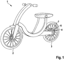
- FIG. 1 shows in a perspective view of an electrically driven bicycle 1, the front wheel 2 steerable and the rear wheel 3 by an electric machine 4, which is presently designed as a wheel hub motor 5, can be driven.
- the electric machine 4 has an axle-fixed stator 6 and a rim-fixed rotor 7, wherein the rotor 7 is arranged and aligned coaxially with the stator 6.
- the rotor 7 is provided with a plurality of permanent magnets arranged side by side on the inside, typically rare-earth magnets.
- the usual construction has the disadvantage that known rotors have virtually no pronounced salience.
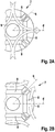
- Salience which comes from the English word “salience”, is meant to refer to FIGS. 2A and 2B be explained in more detail.
- the so-called q-axis describes the direction of magnetic flux generated by the stator current of a return ring 9, perpendicular to the excitation generated by the permanent magnets 8, as in FIGS. 2A and 2B shown.
- the d axis denotes the direction of the magnetic flux generated primarily by the permanent magnets 8.
- L d , L q represent the instantaneous, virtual stator inductances in d and q direction
- Z p corresponds to the number of pole pairs
- ⁇ d , ⁇ q and ⁇ PM the respective flux component in the d and q direction and the permanent magnets PM is.
- the virtual inductances L d and L q result in a motor topology after backward calculation from a ring integral along the considered magnetic fluxes. Since the magnetic permeability of ferromagnetic materials is almost equal to that of air, it can be seen that in permanent magnet motors in the typical surface arrangement the virtual inductances L d and Lq are nearly equal, it does not matter an air gap is kept between the permanent magnets or whether, as usual, the permanent magnets are applied laterally adjacent to each other.
- the permanent magnets of the electric machine 4 are at least partially buried, as in FIGS. 4 to 9 represented, arranged. Due to the advantageous arrangement of the permanent magnets within the return ring 9 carrying the permanent magnets 8, the ring integrals provide different values for L d and Lq. Since L d and Lq describe instantaneous, virtual inductances, these are typically also dependent on the operating state of the electric machine 4, in particular its speed.
- the torque is added due to the at least partially buried arrangements of the permanent magnets 8 in the return ring 9, an additional torque component, the so-called reluctance torque (L d -L q ) * I d * I q .
- MTPA Max Torque per Ampere
- MTPV Maximum Torque per Volt
- ⁇ describes the electric rotor position angle of the rotor 7.
- the measured terminal inductance oscillates with the cosine of the position angle between 3/2 L d and 3/2 Lq.
- the ambiguity of the cosine can be resolved by means of suitable iteration method also without additional sensor and thus a sensorless rotor position angle detection can be performed.
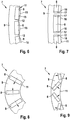
- FIGS. 4 to 9 show, as already mentioned, different embodiments of the advantageous arrangement of the permanent magnet 8 on the return ring. 9
- FIG. 4 shows a first embodiment in which the return ring 9 is provided on its inside with inwardly opened pockets 10, in each of which one of the permanent magnets 8 rests.
- the permanent magnets 8 have a substantially rectangular or square basic shape with a small height compared to the longitudinal extent.
- the pockets 10 are formed such that the permanent magnets 8 are arranged flat on the inner side 11 of the return ring 9, so that their height extends substantially radially.
- the pockets 10 are adapted in shape to the shape of the permanent magnets 8, so that they are kept recorded in the pockets 10 substantially free of play.
- the pockets 10 and permanent magnets 8 are arranged on the inner side 11 of the return ring 9 in the circumferential direction spaced apart from each other, wherein between adjacent permanent magnets 8 and pockets 10 each have a web 12 of the material of the return ring 9 remains.
- the permanent magnets 8 are arranged buried in the pockets 10 or in the return ring 9.
- the width of the webs 12 and thus the minimum distance between adjacent permanent magnets 8 is at least twice as large as the air gap width between the rotor 7 and the inner stator 6.
- the web 12 is magnetically connected to the permanent magnet 8 and is so far in particular to the Sides of the adjacent permanent magnets 8 so as to be in contact with each other. Furthermore, the radial depth of the pockets 10 is selected such that the permanent magnets 8 are flush with the exposed surface 13 with the webs 12 flush on the inside 11, so that substantially a continuous inner surface is formed on the inside 11, which contributes to noise reduction.
- the usable Torque speed range of the electric machine 4 increases without the size of the electric machine 4 itself would have to be extended.
- the pronounced salience allows the electric machine 4 to provide boost power of up to 50% over rated power for up to 30 seconds without overheating.
- the electric machine 4 can be operated for control and regulation by means of encoderless rotor position detection, wherein the rotor position can be accurately detected especially at standstill.
- the control can be determined by the suitably electrically commutated electric machine 4 in conjunction with a field-oriented control for sensorless rotor position detection by measuring the Motorimpendanz, for example by introducing a high-frequency test signal into the stator and measuring the inductive response.
- the permanent magnets 8 are presently designed as ferrite magnets, which are much cheaper to purchase in comparison to the otherwise used rare earth magnets, whereby the manufacturing cost of the electric machine 4 and the bicycle 1 are lowered.
- FIG. 5 shown second embodiment of the rotor 7 differs from the previous embodiment in that the lying between adjacent permanent magnets 8 webs 12 is not flush with the free surfaces 13 of the permanent magnets 8, but have a semi-circular end 14 which the respective web 12 a D Gives shape.
- FIG. 6 shows a third embodiment, which differs from the embodiment FIG. 4 differs in that the pockets 10 are formed closed, so that the permanent magnets 8 are completely buried in the return ring 9.
- the pockets 10 are provided on the inner side 11 of the return ring 9 with an overlap 15, which is formed from the material of the return ring 9 and in particular is formed integrally therewith.
- the respective cover 15 extends from one web 12 to the next via a pocket 10 and the permanent magnets 8 located therein FIG.
- the cover 15 is advantageously provided in the direction of the air gap, ie in the direction of the stator 6, with a cycloid-like shape, so that the attachment point of the cycloids is in each case in the middle of the respective web 12, on a radius outside the inner magnetic surface or the previously free surface 13 of the respective permanent magnet 8 in order to minimize the leakage magnetic flux between adjacent permanent magnets 8.
- FIG. 7 shown fourth embodiment differs from the previous embodiment in that between the webs 12 and the permanent magnet 8 each have a lateral air pocket 16 is provided.
- the air pockets 16 are introduced to the permanent magnet 8 and the webs 12 that they each air gap side each have a narrow, magnetically rapidly saturating transverse web 17 which closes the return ring 9 on the inside to minimize the magnetic leakage flux between adjacent permanent magnets 8.
- the air pockets 16 thus extend radially beyond the height of the permanent magnets 8 into the material of the return ring 9 as far as the respective transverse webs 17.
- FIG. 8 shown fifth embodiment shows the return ring 9 of the rotor 7, in which the permanent magnets 8 are also arranged buried.
- the permanent magnets 8 are arranged in the shape of a spike in the return ring material, so that they extend radially in the return ring 9. Adjacent permanent magnets 8 are thus V-shaped to each other in the return ring 9.
- FIG. 9 shows a sixth embodiment in which the permanent magnets 8 are completely buried in the return ring 9 and V-shaped with alternating orientation of adjacent permanent magnet pairs are arranged.
- the alternating orientation results in a zigzag-shaped course of the permanent magnets 8 in the return ring 9.
- this leads to a flux concentration acting radially in the stator direction.
- the spreading of the permanent magnet pairs thereby increases the effective reluctance torque of the electric machine 4.
- it proves to be advantageous if in the direction perpendicular to the direction of magnetization between the permanent magnet and the material of the return ring 9 air pockets are introduced (not shown here) to magnetic Minimize leakage flux between adjacent magnets.
Landscapes
- Engineering & Computer Science (AREA)
- Power Engineering (AREA)
- Chemical & Material Sciences (AREA)
- Combustion & Propulsion (AREA)
- Transportation (AREA)
- Mechanical Engineering (AREA)
- Permanent Field Magnets Of Synchronous Machinery (AREA)
- Permanent Magnet Type Synchronous Machine (AREA)
- Connection Of Motors, Electrical Generators, Mechanical Devices, And The Like (AREA)
- Arrangement Or Mounting Of Propulsion Units For Vehicles (AREA)
Applications Claiming Priority (2)
| Application Number | Priority Date | Filing Date | Title |
|---|---|---|---|
| DE102012205558A DE102012205558A1 (de) | 2012-04-04 | 2012-04-04 | Elektrisch angetriebenes Zweirad |
| PCT/EP2013/056501 WO2013149902A1 (de) | 2012-04-04 | 2013-03-27 | Elektrisch angetriebenes zweirad |
Publications (2)
| Publication Number | Publication Date |
|---|---|
| EP2834142A1 EP2834142A1 (de) | 2015-02-11 |
| EP2834142B1 true EP2834142B1 (de) | 2017-07-05 |
Family
ID=47998451
Family Applications (1)
| Application Number | Title | Priority Date | Filing Date |
|---|---|---|---|
| EP13712555.5A Active EP2834142B1 (de) | 2012-04-04 | 2013-03-27 | Elektrisch angetriebenes zweirad |
Country Status (6)
| Country | Link |
|---|---|
| EP (1) | EP2834142B1 (en:Method) |
| KR (1) | KR20150000883A (en:Method) |
| CN (1) | CN104185591A (en:Method) |
| DE (1) | DE102012205558A1 (en:Method) |
| IN (1) | IN2014DN07814A (en:Method) |
| WO (1) | WO2013149902A1 (en:Method) |
Families Citing this family (1)
| Publication number | Priority date | Publication date | Assignee | Title |
|---|---|---|---|---|
| US10811946B1 (en) * | 2019-04-02 | 2020-10-20 | GM Global Technology Operations LLC | Cycloidal reluctance motor with rotor permanent magnets |
Family Cites Families (8)
| Publication number | Priority date | Publication date | Assignee | Title |
|---|---|---|---|---|
| DE3028269A1 (de) * | 1980-07-25 | 1982-02-11 | Siemens AG, 1000 Berlin und 8000 München | Permanentmagneterregte elektrische maschine |
| JP3835201B2 (ja) * | 2001-05-08 | 2006-10-18 | 株式会社明電舎 | 電動アシスト自転車用モータ |
| JP4662220B2 (ja) * | 2001-05-31 | 2011-03-30 | 本田技研工業株式会社 | 電動補助自転車 |
| JP2004222455A (ja) * | 2003-01-16 | 2004-08-05 | Moric Co Ltd | 回転電気機器 |
| CN1521919A (zh) * | 2003-01-16 | 2004-08-18 | 株式会社萌力克 | 旋转电气设备 |
| CA2667784A1 (en) * | 2006-12-12 | 2008-06-19 | Tm4 Inc. | Permanent magnet rotor assembly |
| FR2932618B1 (fr) * | 2008-06-16 | 2010-11-19 | Leroy Somer Moteurs | Rotor a aimants permanents et machine tournante comportant un tel rotor |
| CN201742192U (zh) * | 2010-07-08 | 2011-02-09 | 中国电子科技集团公司第二十一研究所 | 永磁电机切向磁钢转子结构 |
-
2012
- 2012-04-04 DE DE102012205558A patent/DE102012205558A1/de not_active Withdrawn
-
2013
- 2013-03-27 KR KR1020147027882A patent/KR20150000883A/ko not_active Withdrawn
- 2013-03-27 CN CN201380018323.7A patent/CN104185591A/zh active Pending
- 2013-03-27 WO PCT/EP2013/056501 patent/WO2013149902A1/de not_active Ceased
- 2013-03-27 EP EP13712555.5A patent/EP2834142B1/de active Active
- 2013-03-27 IN IN7814DEN2014 patent/IN2014DN07814A/en unknown
Also Published As
| Publication number | Publication date |
|---|---|
| WO2013149902A1 (de) | 2013-10-10 |
| DE102012205558A1 (de) | 2013-10-10 |
| CN104185591A (zh) | 2014-12-03 |
| EP2834142A1 (de) | 2015-02-11 |
| KR20150000883A (ko) | 2015-01-05 |
| IN2014DN07814A (en:Method) | 2015-05-15 |
Similar Documents
| Publication | Publication Date | Title |
|---|---|---|
| DE69629419T2 (de) | Motor mit eingebauten Permanentmagneten | |
| DE69928363T2 (de) | Motor mit im Rotor eingebetteten geteilten Dauermagneten | |
| DE102012220613B4 (de) | Drehende elektrische Maschine | |
| EP2639936B1 (de) | Elektrische Maschine mit permanent erregtem Läufer und zugehöriger permanent erregter Läufer | |
| DE102013101186A1 (de) | Synchronmotor | |
| DE102012222438B4 (de) | Gestalten von Rotorbarrieren zur Abschwächung der Entmagnetisierung in einer Maschine mit innenliegenden Permanentmagneten | |
| DE112012000835T5 (de) | Antriebssystem einer rotierenden elektrischen Maschine | |
| DE112012000830T5 (de) | Antriebssystem für rotierende elektrische Maschine | |
| EP2018696B1 (de) | Elektrische maschine | |
| DE102009038268B4 (de) | Drehstrommotor vom Permanentmagnet-Typ | |
| DE112013006430T5 (de) | Motor | |
| DE112017002761T5 (de) | Drehende elektrische maschine | |
| DE19934033A1 (de) | Reluktanzmotor | |
| EP3172829B1 (de) | Verfahren zum bestimmen einer rotorfrequenz und/oder eines rotorwinkels eines rotors einer reluktanzmaschine, steuereinrichtung sowie antriebsanordnung | |
| DE102019214623B4 (de) | Synchronmaschine, elektrische Antriebseinrichtung umfassend eine Synchronmaschine, sowie Ansteuerverfahren für eine Synchronmaschine | |
| DE102014222064B4 (de) | Elektrische Maschine | |
| DE112017000584T5 (de) | Rotor und Verfahren zur Auslegung des Rotors | |
| DE102013219067A1 (de) | Elektrische drehmaschine mit innenliegenden dauermagneten | |
| DE102013219106A1 (de) | Elektrische drehmaschine mit innenliegenden dauermagneten | |
| EP2999090B1 (de) | Permanenterregter Läufer mit geführtem Magnetfeld | |
| DE102012205672A1 (de) | Elektrisch angetriebenes Zweirad | |
| DE102013219222B4 (de) | Elektrische Drehmaschine mit innenliegenden Dauermagneten | |
| EP2834142B1 (de) | Elektrisch angetriebenes zweirad | |
| DE102020126339A1 (de) | Magnetische Einheit einer rotierenden elektrischen Maschine | |
| DE102010010434A1 (de) | Rotor für eine elektrische Maschine |
Legal Events
| Date | Code | Title | Description |
|---|---|---|---|
| PUAI | Public reference made under article 153(3) epc to a published international application that has entered the european phase |
Free format text: ORIGINAL CODE: 0009012 |
|
| 17P | Request for examination filed |
Effective date: 20141104 |
|
| AK | Designated contracting states |
Kind code of ref document: A1 Designated state(s): AL AT BE BG CH CY CZ DE DK EE ES FI FR GB GR HR HU IE IS IT LI LT LU LV MC MK MT NL NO PL PT RO RS SE SI SK SM TR |
|
| AX | Request for extension of the european patent |
Extension state: BA ME |
|
| DAX | Request for extension of the european patent (deleted) | ||
| GRAP | Despatch of communication of intention to grant a patent |
Free format text: ORIGINAL CODE: EPIDOSNIGR1 |
|
| INTG | Intention to grant announced |
Effective date: 20170120 |
|
| GRAS | Grant fee paid |
Free format text: ORIGINAL CODE: EPIDOSNIGR3 |
|
| GRAA | (expected) grant |
Free format text: ORIGINAL CODE: 0009210 |
|
| AK | Designated contracting states |
Kind code of ref document: B1 Designated state(s): AL AT BE BG CH CY CZ DE DK EE ES FI FR GB GR HR HU IE IS IT LI LT LU LV MC MK MT NL NO PL PT RO RS SE SI SK SM TR |
|
| REG | Reference to a national code |
Ref country code: GB Ref legal event code: FG4D Free format text: NOT ENGLISH |
|
| REG | Reference to a national code |
Ref country code: CH Ref legal event code: EP |
|
| REG | Reference to a national code |
Ref country code: AT Ref legal event code: REF Ref document number: 906390 Country of ref document: AT Kind code of ref document: T Effective date: 20170715 |
|
| REG | Reference to a national code |
Ref country code: IE Ref legal event code: FG4D Free format text: LANGUAGE OF EP DOCUMENT: GERMAN |
|
| REG | Reference to a national code |
Ref country code: DE Ref legal event code: R096 Ref document number: 502013007688 Country of ref document: DE |
|
| REG | Reference to a national code |
Ref country code: NL Ref legal event code: MP Effective date: 20170705 |
|
| REG | Reference to a national code |
Ref country code: LT Ref legal event code: MG4D |
|
| PG25 | Lapsed in a contracting state [announced via postgrant information from national office to epo] |
Ref country code: NL Free format text: LAPSE BECAUSE OF FAILURE TO SUBMIT A TRANSLATION OF THE DESCRIPTION OR TO PAY THE FEE WITHIN THE PRESCRIBED TIME-LIMIT Effective date: 20170705 Ref country code: NO Free format text: LAPSE BECAUSE OF FAILURE TO SUBMIT A TRANSLATION OF THE DESCRIPTION OR TO PAY THE FEE WITHIN THE PRESCRIBED TIME-LIMIT Effective date: 20171005 Ref country code: FI Free format text: LAPSE BECAUSE OF FAILURE TO SUBMIT A TRANSLATION OF THE DESCRIPTION OR TO PAY THE FEE WITHIN THE PRESCRIBED TIME-LIMIT Effective date: 20170705 Ref country code: SE Free format text: LAPSE BECAUSE OF FAILURE TO SUBMIT A TRANSLATION OF THE DESCRIPTION OR TO PAY THE FEE WITHIN THE PRESCRIBED TIME-LIMIT Effective date: 20170705 Ref country code: HR Free format text: LAPSE BECAUSE OF FAILURE TO SUBMIT A TRANSLATION OF THE DESCRIPTION OR TO PAY THE FEE WITHIN THE PRESCRIBED TIME-LIMIT Effective date: 20170705 Ref country code: LT Free format text: LAPSE BECAUSE OF FAILURE TO SUBMIT A TRANSLATION OF THE DESCRIPTION OR TO PAY THE FEE WITHIN THE PRESCRIBED TIME-LIMIT Effective date: 20170705 |
|
| PG25 | Lapsed in a contracting state [announced via postgrant information from national office to epo] |
Ref country code: PL Free format text: LAPSE BECAUSE OF FAILURE TO SUBMIT A TRANSLATION OF THE DESCRIPTION OR TO PAY THE FEE WITHIN THE PRESCRIBED TIME-LIMIT Effective date: 20170705 Ref country code: BG Free format text: LAPSE BECAUSE OF FAILURE TO SUBMIT A TRANSLATION OF THE DESCRIPTION OR TO PAY THE FEE WITHIN THE PRESCRIBED TIME-LIMIT Effective date: 20171005 Ref country code: ES Free format text: LAPSE BECAUSE OF FAILURE TO SUBMIT A TRANSLATION OF THE DESCRIPTION OR TO PAY THE FEE WITHIN THE PRESCRIBED TIME-LIMIT Effective date: 20170705 Ref country code: RS Free format text: LAPSE BECAUSE OF FAILURE TO SUBMIT A TRANSLATION OF THE DESCRIPTION OR TO PAY THE FEE WITHIN THE PRESCRIBED TIME-LIMIT Effective date: 20170705 Ref country code: LV Free format text: LAPSE BECAUSE OF FAILURE TO SUBMIT A TRANSLATION OF THE DESCRIPTION OR TO PAY THE FEE WITHIN THE PRESCRIBED TIME-LIMIT Effective date: 20170705 Ref country code: GR Free format text: LAPSE BECAUSE OF FAILURE TO SUBMIT A TRANSLATION OF THE DESCRIPTION OR TO PAY THE FEE WITHIN THE PRESCRIBED TIME-LIMIT Effective date: 20171006 Ref country code: IS Free format text: LAPSE BECAUSE OF FAILURE TO SUBMIT A TRANSLATION OF THE DESCRIPTION OR TO PAY THE FEE WITHIN THE PRESCRIBED TIME-LIMIT Effective date: 20171105 |
|
| REG | Reference to a national code |
Ref country code: DE Ref legal event code: R097 Ref document number: 502013007688 Country of ref document: DE |
|
| PG25 | Lapsed in a contracting state [announced via postgrant information from national office to epo] |
Ref country code: CZ Free format text: LAPSE BECAUSE OF FAILURE TO SUBMIT A TRANSLATION OF THE DESCRIPTION OR TO PAY THE FEE WITHIN THE PRESCRIBED TIME-LIMIT Effective date: 20170705 Ref country code: RO Free format text: LAPSE BECAUSE OF FAILURE TO SUBMIT A TRANSLATION OF THE DESCRIPTION OR TO PAY THE FEE WITHIN THE PRESCRIBED TIME-LIMIT Effective date: 20170705 Ref country code: DK Free format text: LAPSE BECAUSE OF FAILURE TO SUBMIT A TRANSLATION OF THE DESCRIPTION OR TO PAY THE FEE WITHIN THE PRESCRIBED TIME-LIMIT Effective date: 20170705 |
|
| PLBE | No opposition filed within time limit |
Free format text: ORIGINAL CODE: 0009261 |
|
| STAA | Information on the status of an ep patent application or granted ep patent |
Free format text: STATUS: NO OPPOSITION FILED WITHIN TIME LIMIT |
|
| PG25 | Lapsed in a contracting state [announced via postgrant information from national office to epo] |
Ref country code: EE Free format text: LAPSE BECAUSE OF FAILURE TO SUBMIT A TRANSLATION OF THE DESCRIPTION OR TO PAY THE FEE WITHIN THE PRESCRIBED TIME-LIMIT Effective date: 20170705 Ref country code: SM Free format text: LAPSE BECAUSE OF FAILURE TO SUBMIT A TRANSLATION OF THE DESCRIPTION OR TO PAY THE FEE WITHIN THE PRESCRIBED TIME-LIMIT Effective date: 20170705 Ref country code: IT Free format text: LAPSE BECAUSE OF FAILURE TO SUBMIT A TRANSLATION OF THE DESCRIPTION OR TO PAY THE FEE WITHIN THE PRESCRIBED TIME-LIMIT Effective date: 20170705 Ref country code: SK Free format text: LAPSE BECAUSE OF FAILURE TO SUBMIT A TRANSLATION OF THE DESCRIPTION OR TO PAY THE FEE WITHIN THE PRESCRIBED TIME-LIMIT Effective date: 20170705 |
|
| 26N | No opposition filed |
Effective date: 20180406 |
|
| PG25 | Lapsed in a contracting state [announced via postgrant information from national office to epo] |
Ref country code: SI Free format text: LAPSE BECAUSE OF FAILURE TO SUBMIT A TRANSLATION OF THE DESCRIPTION OR TO PAY THE FEE WITHIN THE PRESCRIBED TIME-LIMIT Effective date: 20170705 |
|
| PG25 | Lapsed in a contracting state [announced via postgrant information from national office to epo] |
Ref country code: MT Free format text: LAPSE BECAUSE OF FAILURE TO SUBMIT A TRANSLATION OF THE DESCRIPTION OR TO PAY THE FEE WITHIN THE PRESCRIBED TIME-LIMIT Effective date: 20170705 |
|
| REG | Reference to a national code |
Ref country code: CH Ref legal event code: PL |
|
| GBPC | Gb: european patent ceased through non-payment of renewal fee |
Effective date: 20180327 |
|
| PG25 | Lapsed in a contracting state [announced via postgrant information from national office to epo] |
Ref country code: MC Free format text: LAPSE BECAUSE OF FAILURE TO SUBMIT A TRANSLATION OF THE DESCRIPTION OR TO PAY THE FEE WITHIN THE PRESCRIBED TIME-LIMIT Effective date: 20170705 |
|
| REG | Reference to a national code |
Ref country code: BE Ref legal event code: MM Effective date: 20180331 |
|
| REG | Reference to a national code |
Ref country code: IE Ref legal event code: MM4A |
|
| PG25 | Lapsed in a contracting state [announced via postgrant information from national office to epo] |
Ref country code: LU Free format text: LAPSE BECAUSE OF NON-PAYMENT OF DUE FEES Effective date: 20180327 |
|
| PG25 | Lapsed in a contracting state [announced via postgrant information from national office to epo] |
Ref country code: IE Free format text: LAPSE BECAUSE OF NON-PAYMENT OF DUE FEES Effective date: 20180327 |
|
| PG25 | Lapsed in a contracting state [announced via postgrant information from national office to epo] |
Ref country code: BE Free format text: LAPSE BECAUSE OF NON-PAYMENT OF DUE FEES Effective date: 20180331 Ref country code: LI Free format text: LAPSE BECAUSE OF NON-PAYMENT OF DUE FEES Effective date: 20180331 Ref country code: GB Free format text: LAPSE BECAUSE OF NON-PAYMENT OF DUE FEES Effective date: 20180327 Ref country code: CH Free format text: LAPSE BECAUSE OF NON-PAYMENT OF DUE FEES Effective date: 20180331 |
|
| PG25 | Lapsed in a contracting state [announced via postgrant information from national office to epo] |
Ref country code: FR Free format text: LAPSE BECAUSE OF NON-PAYMENT OF DUE FEES Effective date: 20180331 |
|
| REG | Reference to a national code |
Ref country code: AT Ref legal event code: MM01 Ref document number: 906390 Country of ref document: AT Kind code of ref document: T Effective date: 20180327 |
|
| PG25 | Lapsed in a contracting state [announced via postgrant information from national office to epo] |
Ref country code: AT Free format text: LAPSE BECAUSE OF NON-PAYMENT OF DUE FEES Effective date: 20180327 |
|
| PG25 | Lapsed in a contracting state [announced via postgrant information from national office to epo] |
Ref country code: TR Free format text: LAPSE BECAUSE OF FAILURE TO SUBMIT A TRANSLATION OF THE DESCRIPTION OR TO PAY THE FEE WITHIN THE PRESCRIBED TIME-LIMIT Effective date: 20170705 |
|
| PG25 | Lapsed in a contracting state [announced via postgrant information from national office to epo] |
Ref country code: PT Free format text: LAPSE BECAUSE OF FAILURE TO SUBMIT A TRANSLATION OF THE DESCRIPTION OR TO PAY THE FEE WITHIN THE PRESCRIBED TIME-LIMIT Effective date: 20170705 |
|
| PG25 | Lapsed in a contracting state [announced via postgrant information from national office to epo] |
Ref country code: HU Free format text: LAPSE BECAUSE OF FAILURE TO SUBMIT A TRANSLATION OF THE DESCRIPTION OR TO PAY THE FEE WITHIN THE PRESCRIBED TIME-LIMIT; INVALID AB INITIO Effective date: 20130327 Ref country code: CY Free format text: LAPSE BECAUSE OF FAILURE TO SUBMIT A TRANSLATION OF THE DESCRIPTION OR TO PAY THE FEE WITHIN THE PRESCRIBED TIME-LIMIT Effective date: 20170705 Ref country code: MK Free format text: LAPSE BECAUSE OF NON-PAYMENT OF DUE FEES Effective date: 20170705 |
|
| PG25 | Lapsed in a contracting state [announced via postgrant information from national office to epo] |
Ref country code: AL Free format text: LAPSE BECAUSE OF FAILURE TO SUBMIT A TRANSLATION OF THE DESCRIPTION OR TO PAY THE FEE WITHIN THE PRESCRIBED TIME-LIMIT Effective date: 20170705 |
|
| PGFP | Annual fee paid to national office [announced via postgrant information from national office to epo] |
Ref country code: DE Payment date: 20250522 Year of fee payment: 13 |