EP2833977B1 - Chemical oxygen generator with chemical cores arranged in parallel - Google Patents
Chemical oxygen generator with chemical cores arranged in parallel Download PDFInfo
- Publication number
- EP2833977B1 EP2833977B1 EP13712115.8A EP13712115A EP2833977B1 EP 2833977 B1 EP2833977 B1 EP 2833977B1 EP 13712115 A EP13712115 A EP 13712115A EP 2833977 B1 EP2833977 B1 EP 2833977B1
- Authority
- EP
- European Patent Office
- Prior art keywords
- chemical
- oxygen generator
- sequentially connected
- core sections
- parallel
- Prior art date
- Legal status (The legal status is an assumption and is not a legal conclusion. Google has not performed a legal analysis and makes no representation as to the accuracy of the status listed.)
- Active
Links
Images


Classifications
-
- A—HUMAN NECESSITIES
- A62—LIFE-SAVING; FIRE-FIGHTING
- A62B—DEVICES, APPARATUS OR METHODS FOR LIFE-SAVING
- A62B7/00—Respiratory apparatus
- A62B7/08—Respiratory apparatus containing chemicals producing oxygen
-
- A—HUMAN NECESSITIES
- A62—LIFE-SAVING; FIRE-FIGHTING
- A62B—DEVICES, APPARATUS OR METHODS FOR LIFE-SAVING
- A62B21/00—Devices for producing oxygen from chemical substances for respiratory apparatus
-
- C—CHEMISTRY; METALLURGY
- C01—INORGANIC CHEMISTRY
- C01B—NON-METALLIC ELEMENTS; COMPOUNDS THEREOF; METALLOIDS OR COMPOUNDS THEREOF NOT COVERED BY SUBCLASS C01C
- C01B13/00—Oxygen; Ozone; Oxides or hydroxides in general
- C01B13/02—Preparation of oxygen
-
- C—CHEMISTRY; METALLURGY
- C01—INORGANIC CHEMISTRY
- C01B—NON-METALLIC ELEMENTS; COMPOUNDS THEREOF; METALLOIDS OR COMPOUNDS THEREOF NOT COVERED BY SUBCLASS C01C
- C01B13/00—Oxygen; Ozone; Oxides or hydroxides in general
- C01B13/02—Preparation of oxygen
- C01B13/0203—Preparation of oxygen from inorganic compounds
- C01B13/0218—Chlorate
-
- C—CHEMISTRY; METALLURGY
- C01—INORGANIC CHEMISTRY
- C01B—NON-METALLIC ELEMENTS; COMPOUNDS THEREOF; METALLOIDS OR COMPOUNDS THEREOF NOT COVERED BY SUBCLASS C01C
- C01B13/00—Oxygen; Ozone; Oxides or hydroxides in general
- C01B13/02—Preparation of oxygen
- C01B13/0229—Purification or separation processes
- C01B13/0233—Chemical processing only
-
- C—CHEMISTRY; METALLURGY
- C01—INORGANIC CHEMISTRY
- C01B—NON-METALLIC ELEMENTS; COMPOUNDS THEREOF; METALLOIDS OR COMPOUNDS THEREOF NOT COVERED BY SUBCLASS C01C
- C01B13/00—Oxygen; Ozone; Oxides or hydroxides in general
- C01B13/02—Preparation of oxygen
- C01B13/0296—Generators releasing in a self-sustaining way pure oxygen from a solid charge, without interaction of it with a fluid nor external heating, e.g. chlorate candles or canisters containing them
-
- A—HUMAN NECESSITIES
- A62—LIFE-SAVING; FIRE-FIGHTING
- A62B—DEVICES, APPARATUS OR METHODS FOR LIFE-SAVING
- A62B7/00—Respiratory apparatus
- A62B7/14—Respiratory apparatus for high-altitude aircraft
Definitions
- This invention relates generally to chemical oxygen generators for civilian and military airplanes to provide supplemental oxygen, and more particularly relates to a chemical oxygen generator having a chemical oxygen generating core assembly composed of multiple sections, with at least two of the sections arranged in parallel so that a duration of operation of the chemical oxygen generator can be extended without increasing the length of the generator.
- Chemical oxygen generators are typically used in situations requiring the generation of supplemental oxygen, such as in aviation and in submarines, for example, and in other similar settings where it is useful to furnish a convenient and reliable supply of oxygen gas of breathable quality.
- Chemical oxygen generating compositions based upon the decomposition of alkali metal chlorates or perchlorates have long been used as an emergency source of breathable oxygen in passenger aircraft, for example.
- An aircraft oxygen generator is commonly preprogrammed according to the descent profile of a given type of airplane, and must meet the minimum oxygen flow requirement at all times during a descent.
- the oxygen generating reaction is initiated at one end of the core, the reaction front propagates along the longitudinal axis toward the other end of the core as oxygen is generated.
- the reaction zone moves at a steady, repeatable rate governed by the amounts of fuel and catalyst incorporated at a given point along the length of the core.
- a reaction front moves from the ignition end to the outlet end of the generator, producing oxygen.
- One conventional chemical oxygen generator includes an oxygen generating candle having a chemical core with a slightly tapered cylindrical shape. Once initiated, the candle will sustain decomposition to release breathable oxygen until the candle is completely reacted. However, since the reaction front needs to move at a certain linear rate, the length of the chemical core has to be increased when a relatively longer duration of operation is needed. Due to the limited space available in aircraft, it is difficult to increase the generator length beyond the length of the typical space envelope provided for an oxygen generator, so that heavier cores are typically used in such conventional chemical oxygen generators to insure the chemical cores have sufficient duration.
- One known chemical oxygen generator includes an elongate rigid thermal insulating section, and a conduit section on one side of the rigid section providing multiple gas flow paths for conducting released oxygen from a burning candle along the plate for increasing the burning action of the burning portion of the candle and pre-heating the unburned portion of the candle.
- a plurality of the plates are combined to form a honeycomb type separator assembly made from interlocking ceramic plates for surrounding a candle, and a number of such separator assemblies are combined to form a multi-candle oxygen generator for oxygen supply flow profiles that require a high initial flow rate.
- the honeycomb type separator occupies a substantial volume and increases weight of the chemical candle, and is not suitable for aviation use.
- the reaction front In order for the oxygen generating reaction in a chemical oxygen generator to remain sufficiently stable that the reaction is not extinguished, the reaction front must move with a sufficiently high linear velocity. If the reaction front moves too slowly, the reaction becomes less controllable, and may stop. In order to maintain a minimum reaction front linear velocity and meet requirements for a duration of operation of the chemical oxygen generator, typically it has been necessary to increase the weight or length of the chemical core of the chemical oxygen generator, resulting in an increase in the weight or length of the chemical oxygen generator. Some aircraft may require a very long duration, while requiring a high flow rate in the first few minutes, such as the profile shown in FIG. 3 .
- Chlorate/perchlorate based oxygen generating compositions contain about 0.5-15% by weight of metal powder for use as a fuel selected from the group consisting of iron, nickel, cobalt and mixtures thereof; about 0.1% to about 15% by weight of at least one transition metal oxide catalyst; greater than 5% to about 25% by weight of an alkali metal silicate as a reaction rate and core rheology modifier, binder and chlorine suppresser; and the remainder substantially comprising an oxygen source selected from the group consisting of alkali metal chlorates, alkali metal perchlorates, and mixtures thereof.
- the alkali metal silicate can be selected from the group consisting of sodium metasilicate, sodium orthosilicate, lithium metasilicate, potassium silicate, and mixtures thereof.
- the oxygen generating composition can also optionally contain a binder selected from the group consisting of glass powder, fiber glass and mixtures thereof.
- the present invention provides for a chemical oxygen generator including a plurality of parallel sequentially connected chemical core sections that extend the duration of operation of the chemical oxygen generator without increasing the weight or length of the generator.
- the present invention accordingly provides for a chemical oxygen generator 10 including a chemical oxygen generator housing 12 containing a chemical core assembly 14 including one or more oxygen generating compositions for producing a supplemental breathable gas when a reaction front propagates through the oxygen generating composition.
- the chemical oxygen generator housing is typically formed of stainless steel, and can be formed by wrapping the chemical core assembly in a stainless steel sheet, perforated stainless steel sheet, or stainless steel wire mesh, for example, to form the main generally cylindrical body 18 of the chemical oxygen generator housing, although other suitable similar materials may also be used.
- the wrapped core assembly is typically held tightly between two stainless steel cups 20 that are fixedly attached to both ends 22a, 22b of the main generally cylindrical body of the chemical oxygen generator housing.
- the oxygen generating compositions of the chemical core assembly are typically sodium chlorate based oxygen generating compositions.
- the chemical core assembly includes a first or ignition end 24, shown at the top of the figures, and an opposing second or outlet end 26, shown at the bottom of the figures.
- the chemical core assembly preferably is formed of solid material, and is generally is constructed so as to have the form of a cylinder, with a length much longer than its diameter.
- the chemical core assembly also preferably has higher activity at the ignition or combustion initiation end, and becomes progressively less active toward the other end, so as to have an oxygen generation profile or oxygen flow curve that satisfies the oxygen requirements for a given aircraft descent profile.
- the chemical core assembly preferably is formed to have a chemical core ignition plate or hot plate 28 disposed in the first or ignition end of the chemical oxygen generator housing, and typically includes a percussion primer cap 30.
- the chemical core ignition plate can be ignited directly by the percussion primer cap, or by the heat of an activation powder that is ignited by the percussion primer cap.
- the chemical core ignition plate can also be ignited by other means such as hot wire or a water initiated chemical composition.
- a chemical core high reactivity section 32 including a highly reactive oxygen generating composition is preferably disposed in the chemical oxygen generator housing immediately adjacent to and contiguous with or touching the chemical core ignition plate. Once ignited, the ignition plate reacts rapidly, and the heat from the reaction will start the reaction of the high reactivity section.
- the ignition plate may have the same diameter as that of the high reactive section, or may have a much smaller diameter than the high reactive section.
- a recess 34 can be formed in a middle area of the high reactivity section, and a portion of the chemical core ignition plate can be located inside this recess.
- the ignition plate and the high reactivity section can also be constructed as a single piece.
- the chemical core assembly also advantageously includes a plurality of parallel chemical core sections disposed in the chemical oxygen generator housing, such as first and second parallel chemical core sections 38a, 38b, although the plurality of parallel chemical core sections may alternatively include three or more parallel sections.
- the high reactivity section preferably not only has a high chemical reactivity relative to the chemical reactivity of the plurality of parallel chemical core sections, but also preferably has a cross sectional area that is relatively larger than the cross sectional area of each of the plurality of parallel chemical core sections, so that the chemical core high reactivity section thus is capable of generating oxygen gas comparatively rapidly to provide a relatively high initial oxygen flow rate that is required by many aircraft descent profiles, as shown in Fig. 3 .
- the ignition plate and high reactivity layer may substantially cover the plurality of parallel core sections, although as is illustrated in Figs. 2A and 2B , the ignition plate and high reactivity layer may cover only one of the plurality of parallel core sections.
- the plurality of parallel chemical core sections are formed of at least one oxygen generating composition, and include first ends 40a, 40b oriented toward the ignition end of the chemical oxygen generator, second ends 42a, 42b oriented toward the outlet end of the chemical oxygen generator, and body portions 44a, 44b between the first and second ends, respectively, extending a length 46a, 46b along a longitudinal axis 48 of the chemical oxygen generator housing.
- the first end of the first parallel chemical core section is preferably disposed immediately adjacent to and contiguous with or touching the chemical core high reactivity section.
- the parallel sections can be made with substantial equal cross sectional area, or alternatively, the parallel section that is positioned to react first can be made to have a slightly larger cross sectional area than that of the other parallel section or sections.
- a thermal insulation layer 50 is also preferably disposed in the chemical oxygen generator housing between the first end of the second parallel chemical core section and the chemical core ignition plate, between the first end of the second parallel chemical core section and the first end of the first parallel chemical core section, and between the body of the second parallel chemical core section and the body of said first parallel chemical core section.
- the thermal insulation layer between the high reactivity section and the second parallel section and between the parallel sections prevents the second parallel section from reacting before the first parallel section is consumed.
- the insulation can be a prefabricated material or can be incorporated in-situ as part of the chemical core manufacturing process, and is typically formed as a light weight and rigid thermal insulating plate from a refractory fiber, such as an alumino-silicate refractory ceramic fiber, or a ceramic fiber paper for high temperature thermal insulation such as a ceramic wool impregnated with calcium hydroxide, for example, both available from UNIFRAX CORPORATION, under the brand name FIBERFRAX, or other similar high temperature thermal insulation materials, may be suitable. Calcium hydroxide can also be included in the thermal insulation layer to help remove residual chlorine in the oxygen produced.
- a light weight refractory board such as a refractory board made from calcium silicate, flexible insulating materials such as a refractory ceramic fiber high temperature insulation sheet material, glass wool, or lightweight flexible and organic impurity free aerogel insulation for high temperature applications may also be used.
- the chemical core assembly also typically includes a transition section 52, preferably including a highly reactive oxygen generating composition, disposed in the chemical oxygen generator housing between and immediately adjacent to and contiguous with or touching the second end of the first parallel chemical core section and the first end of the second parallel chemical core section.
- a transition section 52 preferably including a highly reactive oxygen generating composition, disposed in the chemical oxygen generator housing between and immediately adjacent to and contiguous with or touching the second end of the first parallel chemical core section and the first end of the second parallel chemical core section.
- this high activity layer at the bottom of the second section makes it easier for the reaction front to propagate from the section on the left hand side to the right hand side.
- the transition section is preferably configured to insure that the reaction front propagates from the second end of the first parallel chemical core section to the second end of the second parallel chemical core section when the reaction front reaches the second end of the first parallel chemical core section.
- the parallel core sections thereby effectively prolong the reaction time without an increase in length.
- the transition section is preferably configured to force the reaction
- the heat starts the reaction of the high reactivity section.
- the reaction then proceeds through the parallel section on the left hand side, the transition section, and then the parallel section on the right hand side.
- the operation duration of the chemical oxygen generator can be nearly doubled without increase in the generator length.
- the heat from the high reactivity section will then start the reaction of the first parallel chemical core section, and the reaction front will propagate toward the outlet end of the first core parallel section.
- the insulation layer between the high reactivity section and the second parallel chemical core section and between the first and second parallel chemical core sections prevents the second parallel chemical core section from reacting before the first parallel chemical core section is consumed.
- the reaction front Once the reaction front reaches the transition section, the reaction front causes the transition section to react. Heat from the transition section then starts the reaction of the second parallel chemical core section, and the reaction front propagates in the second parallel chemical core section from the outlet end toward the ignition end.
- the two parallel core sections can therefore effectively prolong the reaction time without an increase in length.
- the transition section can be oriented at an angle of approximately 45 degrees relative to the longitudinal axis of the chemical oxygen generator housing.
- a split core was loaded with an ignition plate on top of only one half of the chemical core. The transition was done by closing the gap with an extension of the second core half, incorporating a highly reactive layer. This layer was oriented at approximately 45 degrees to the bottom, to force the reaction front to travel orthogonal to the core orientation.
- the ignition plate is ignited by a starting powder 30.
- the reaction heat ignites the chemical core section on the left hand side.
- the reaction front then propagates toward the outlet end (bottom of the core in FIGS. 2A and 2B ).
- reaction front When the reaction front reaches the end of the first section, it starts the reaction of the high reactivity layer. The high reactivity layer then starts the reaction of the section on the right hand side. Once the reaction front reaches the transition section, the reaction front causes the transition section to react. Heat from the transition section then starts the reaction of the second parallel section, and the reaction front then continues to propagate, from the outlet end toward the ignition end.
- the transition section and the two parallel sections may also be made into a single section with a slit in the middle and filled with an insulating layer.
- the oxygen generation flow curve of the one of the chemical oxygen generators with this chemical core arrangement is shown in FIG. 4 . This chemical oxygen generator ran over 60 minutes. The peak at around 32 minutes was due to the high activity transition layer. The peak height can be reduced by modifying the shape of the high activity transition layer.
- the chemical core with the same length without a parallel section arrangement typically runs less than 30 minutes.
Landscapes
- Chemical & Material Sciences (AREA)
- Organic Chemistry (AREA)
- Health & Medical Sciences (AREA)
- Inorganic Chemistry (AREA)
- General Health & Medical Sciences (AREA)
- Pulmonology (AREA)
- Emergency Medicine (AREA)
- Business, Economics & Management (AREA)
- Emergency Management (AREA)
- Chemical Kinetics & Catalysis (AREA)
- General Chemical & Material Sciences (AREA)
- Analytical Chemistry (AREA)
- Oxygen, Ozone, And Oxides In General (AREA)
Description
- This invention relates generally to chemical oxygen generators for civilian and military airplanes to provide supplemental oxygen, and more particularly relates to a chemical oxygen generator having a chemical oxygen generating core assembly composed of multiple sections, with at least two of the sections arranged in parallel so that a duration of operation of the chemical oxygen generator can be extended without increasing the length of the generator.
- Chemical oxygen generators are typically used in situations requiring the generation of supplemental oxygen, such as in aviation and in submarines, for example, and in other similar settings where it is useful to furnish a convenient and reliable supply of oxygen gas of breathable quality. Chemical oxygen generating compositions based upon the decomposition of alkali metal chlorates or perchlorates have long been used as an emergency source of breathable oxygen in passenger aircraft, for example.
- An aircraft oxygen generator is commonly preprogrammed according to the descent profile of a given type of airplane, and must meet the minimum oxygen flow requirement at all times during a descent. When the oxygen generating reaction is initiated at one end of the core, the reaction front propagates along the longitudinal axis toward the other end of the core as oxygen is generated. Ideally, the reaction zone moves at a steady, repeatable rate governed by the amounts of fuel and catalyst incorporated at a given point along the length of the core. Once initiated, a reaction front moves from the ignition end to the outlet end of the generator, producing oxygen.
- One conventional chemical oxygen generator is known that includes an oxygen generating candle having a chemical core with a slightly tapered cylindrical shape. Once initiated, the candle will sustain decomposition to release breathable oxygen until the candle is completely reacted. However, since the reaction front needs to move at a certain linear rate, the length of the chemical core has to be increased when a relatively longer duration of operation is needed. Due to the limited space available in aircraft, it is difficult to increase the generator length beyond the length of the typical space envelope provided for an oxygen generator, so that heavier cores are typically used in such conventional chemical oxygen generators to insure the chemical cores have sufficient duration.
- One known chemical oxygen generator includes an elongate rigid thermal insulating section, and a conduit section on one side of the rigid section providing multiple gas flow paths for conducting released oxygen from a burning candle along the plate for increasing the burning action of the burning portion of the candle and pre-heating the unburned portion of the candle. A plurality of the plates are combined to form a honeycomb type separator assembly made from interlocking ceramic plates for surrounding a candle, and a number of such separator assemblies are combined to form a multi-candle oxygen generator for oxygen supply flow profiles that require a high initial flow rate. The honeycomb type separator occupies a substantial volume and increases weight of the chemical candle, and is not suitable for aviation use.
- In order for the oxygen generating reaction in a chemical oxygen generator to remain sufficiently stable that the reaction is not extinguished, the reaction front must move with a sufficiently high linear velocity. If the reaction front moves too slowly, the reaction becomes less controllable, and may stop. In order to maintain a minimum reaction front linear velocity and meet requirements for a duration of operation of the chemical oxygen generator, typically it has been necessary to increase the weight or length of the chemical core of the chemical oxygen generator, resulting in an increase in the weight or length of the chemical oxygen generator. Some aircraft may require a very long duration, while requiring a high flow rate in the first few minutes, such as the profile shown in
FIG. 3 . - Particularly for aircraft, it would be desirable to provide a chemical oxygen generator that permits extension of the duration of operation of the chemical oxygen generator without increasing the weight or length of the generator. The present invention meets these and other needs.
- Swiss patent publication no.
CH 139956 DE 4142504 and UK patent application publication no.GB 2160187 - US patent no.
US 6,193,907 describes an oxygen generating formulation. Chlorate/perchlorate based oxygen generating compositions contain about 0.5-15% by weight of metal powder for use as a fuel selected from the group consisting of iron, nickel, cobalt and mixtures thereof; about 0.1% to about 15% by weight of at least one transition metal oxide catalyst; greater than 5% to about 25% by weight of an alkali metal silicate as a reaction rate and core rheology modifier, binder and chlorine suppresser; and the remainder substantially comprising an oxygen source selected from the group consisting of alkali metal chlorates, alkali metal perchlorates, and mixtures thereof. The alkali metal silicate can be selected from the group consisting of sodium metasilicate, sodium orthosilicate, lithium metasilicate, potassium silicate, and mixtures thereof. The oxygen generating composition can also optionally contain a binder selected from the group consisting of glass powder, fiber glass and mixtures thereof. - In accordance with the present invention, there is provided a chemical oxygen generator as recited in the accompanying claims.
-
-
Figure 1A is a cross-sectional schematic view of a first embodiment of a chemical oxygen generator core assembly according to the present invention. -
Fig. 1B is a cross-sectional schematic view taken alongline 1B-1B ofFig. 1A . -
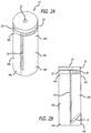
Fig. 2A is a perspective view of a second embodiment of a chemical oxygen generator core assembly according to the present invention. -
Fig. 2B is a cross-sectional schematic view of the chemical oxygen generator core assembly ofFig. 2A . -
Fig. 3 is an idealized oxygen flow profile of a chemical oxygen generator with a relatively long duration. -
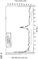
Fig. 4 is an oxygen flow profile of a chemical oxygen generator with a chemical core assembly with parallel sections, according to the present invention. - Referring to the drawings, which are provided by way of example, and not by way of limitation, the present invention provides for a chemical oxygen generator including a plurality of parallel sequentially connected chemical core sections that extend the duration of operation of the chemical oxygen generator without increasing the weight or length of the generator. The present invention accordingly provides for a
chemical oxygen generator 10 including a chemicaloxygen generator housing 12 containing achemical core assembly 14 including one or more oxygen generating compositions for producing a supplemental breathable gas when a reaction front propagates through the oxygen generating composition. The chemical oxygen generator housing is typically formed of stainless steel, and can be formed by wrapping the chemical core assembly in a stainless steel sheet, perforated stainless steel sheet, or stainless steel wire mesh, for example, to form the main generallycylindrical body 18 of the chemical oxygen generator housing, although other suitable similar materials may also be used. The wrapped core assembly is typically held tightly between twostainless steel cups 20 that are fixedly attached to bothends - The oxygen generating compositions of the chemical core assembly are typically sodium chlorate based oxygen generating compositions. As is illustrated in
Figs. 1A to 2B , the chemical core assembly includes a first orignition end 24, shown at the top of the figures, and an opposing second oroutlet end 26, shown at the bottom of the figures. The chemical core assembly preferably is formed of solid material, and is generally is constructed so as to have the form of a cylinder, with a length much longer than its diameter. The chemical core assembly also preferably has higher activity at the ignition or combustion initiation end, and becomes progressively less active toward the other end, so as to have an oxygen generation profile or oxygen flow curve that satisfies the oxygen requirements for a given aircraft descent profile. - The chemical core assembly preferably is formed to have a chemical core ignition plate or
hot plate 28 disposed in the first or ignition end of the chemical oxygen generator housing, and typically includes apercussion primer cap 30. The chemical core ignition plate can be ignited directly by the percussion primer cap, or by the heat of an activation powder that is ignited by the percussion primer cap. The chemical core ignition plate can also be ignited by other means such as hot wire or a water initiated chemical composition. - A chemical core
high reactivity section 32 including a highly reactive oxygen generating composition is preferably disposed in the chemical oxygen generator housing immediately adjacent to and contiguous with or touching the chemical core ignition plate. Once ignited, the ignition plate reacts rapidly, and the heat from the reaction will start the reaction of the high reactivity section. The ignition plate may have the same diameter as that of the high reactive section, or may have a much smaller diameter than the high reactive section. Arecess 34 can be formed in a middle area of the high reactivity section, and a portion of the chemical core ignition plate can be located inside this recess. Alternatively, the ignition plate and the high reactivity section can also be constructed as a single piece. - The chemical core assembly also advantageously includes a plurality of parallel chemical core sections disposed in the chemical oxygen generator housing, such as first and second parallel
chemical core sections Fig. 3 . As is illustrated inFig. 1A , the ignition plate and high reactivity layer may substantially cover the plurality of parallel core sections, although as is illustrated inFigs. 2A and 2B , the ignition plate and high reactivity layer may cover only one of the plurality of parallel core sections. - The plurality of parallel chemical core sections are formed of at least one oxygen generating composition, and include first ends 40a, 40b oriented toward the ignition end of the chemical oxygen generator, second ends 42a, 42b oriented toward the outlet end of the chemical oxygen generator, and body portions 44a, 44b between the first and second ends, respectively, extending a
length longitudinal axis 48 of the chemical oxygen generator housing. The first end of the first parallel chemical core section is preferably disposed immediately adjacent to and contiguous with or touching the chemical core high reactivity section. The parallel sections can be made with substantial equal cross sectional area, or alternatively, the parallel section that is positioned to react first can be made to have a slightly larger cross sectional area than that of the other parallel section or sections. - A
thermal insulation layer 50 is also preferably disposed in the chemical oxygen generator housing between the first end of the second parallel chemical core section and the chemical core ignition plate, between the first end of the second parallel chemical core section and the first end of the first parallel chemical core section, and between the body of the second parallel chemical core section and the body of said first parallel chemical core section. The thermal insulation layer between the high reactivity section and the second parallel section and between the parallel sections prevents the second parallel section from reacting before the first parallel section is consumed. The insulation can be a prefabricated material or can be incorporated in-situ as part of the chemical core manufacturing process, and is typically formed as a light weight and rigid thermal insulating plate from a refractory fiber, such as an alumino-silicate refractory ceramic fiber, or a ceramic fiber paper for high temperature thermal insulation such as a ceramic wool impregnated with calcium hydroxide, for example, both available from UNIFRAX CORPORATION, under the brand name FIBERFRAX, or other similar high temperature thermal insulation materials, may be suitable. Calcium hydroxide can also be included in the thermal insulation layer to help remove residual chlorine in the oxygen produced. A light weight refractory board such as a refractory board made from calcium silicate, flexible insulating materials such as a refractory ceramic fiber high temperature insulation sheet material, glass wool, or lightweight flexible and organic impurity free aerogel insulation for high temperature applications may also be used. - The chemical core assembly also typically includes a
transition section 52, preferably including a highly reactive oxygen generating composition, disposed in the chemical oxygen generator housing between and immediately adjacent to and contiguous with or touching the second end of the first parallel chemical core section and the first end of the second parallel chemical core section. Referring toFigs. 1A ,2A and 2B , this high activity layer at the bottom of the second section makes it easier for the reaction front to propagate from the section on the left hand side to the right hand side. The transition section is preferably configured to insure that the reaction front propagates from the second end of the first parallel chemical core section to the second end of the second parallel chemical core section when the reaction front reaches the second end of the first parallel chemical core section. The parallel core sections thereby effectively prolong the reaction time without an increase in length. The transition section is preferably configured to force the reaction front to travel from the second end of the first parallel chemical core section to the second end of the second parallel chemical core section orthogonally to the longitudinal axis of the chemical oxygen generator housing. - Once the ignition plate is ignited, the heat starts the reaction of the high reactivity section. The reaction then proceeds through the parallel section on the left hand side, the transition section, and then the parallel section on the right hand side. In the arrangement, the operation duration of the chemical oxygen generator can be nearly doubled without increase in the generator length. The heat from the high reactivity section will then start the reaction of the first parallel chemical core section, and the reaction front will propagate toward the outlet end of the first core parallel section. The insulation layer between the high reactivity section and the second parallel chemical core section and between the first and second parallel chemical core sections prevents the second parallel chemical core section from reacting before the first parallel chemical core section is consumed. Once the reaction front reaches the transition section, the reaction front causes the transition section to react. Heat from the transition section then starts the reaction of the second parallel chemical core section, and the reaction front propagates in the second parallel chemical core section from the outlet end toward the ignition end. The two parallel core sections can therefore effectively prolong the reaction time without an increase in length.
- As is illustrated in
Fig. 2B , in one presently preferred aspect, the transition section can be oriented at an angle of approximately 45 degrees relative to the longitudinal axis of the chemical oxygen generator housing. In this arrangement, a split core was loaded with an ignition plate on top of only one half of the chemical core. The transition was done by closing the gap with an extension of the second core half, incorporating a highly reactive layer. This layer was oriented at approximately 45 degrees to the bottom, to force the reaction front to travel orthogonal to the core orientation. The ignition plate is ignited by a startingpowder 30. The reaction heat ignites the chemical core section on the left hand side. The reaction front then propagates toward the outlet end (bottom of the core inFIGS. 2A and 2B ). When the reaction front reaches the end of the first section, it starts the reaction of the high reactivity layer. The high reactivity layer then starts the reaction of the section on the right hand side. Once the reaction front reaches the transition section, the reaction front causes the transition section to react. Heat from the transition section then starts the reaction of the second parallel section, and the reaction front then continues to propagate, from the outlet end toward the ignition end. The transition section and the two parallel sections may also be made into a single section with a slit in the middle and filled with an insulating layer. The oxygen generation flow curve of the one of the chemical oxygen generators with this chemical core arrangement is shown inFIG. 4 . This chemical oxygen generator ran over 60 minutes. The peak at around 32 minutes was due to the high activity transition layer. The peak height can be reduced by modifying the shape of the high activity transition layer. The chemical core with the same length without a parallel section arrangement typically runs less than 30 minutes. - It will be apparent from the foregoing that while particular forms of the invention have been illustrated and described, various modifications can be made without departing from the scope of the invention as defined by the appended claims.
Claims (13)
- A chemical oxygen generator (10) including an oxygen generating composition for producing a supplemental breathable gas when a reaction front propagates through the oxygen generating composition, the chemical oxygen generator (10) comprising:a chemical oxygen generator housing (12) having an ignition end (24) and an opposing oxygen outlet end (26);a chemical core ignition plate (28) disposed in said ignition end (24) of said chemical oxygen generator housing (12);a chemical core high reactivity section (32) including an oxygen generating composition disposed in said chemical oxygen generator housing (12) immediately adjacent to and contiguous with said chemical core ignition plate (28);a plurality of parallel sequentially connected chemical core sections (38a, 38b) disposed in said chemical oxygen generator housing (12), said plurality of parallel sequentially connected chemical core sections (38a, 38b) each including an oxygen generating composition and having first ends (40a, 40b) oriented toward said ignition end (24) of said chemical oxygen generator (10), second ends (42a, 42b) oriented toward said outlet end (26) of said chemical oxygen generator (10), and body portions between said first and second ends extending a length (46a, 46b) along a longitudinal axis (48) of said chemical oxygen generator housing (12), a first end (40a) of a first one (38a) of said plurality of parallel sequentially connected chemical core sections (38a, 38b) disposed immediately adjacent to and contiguous with said chemical core high reactivity section (32);a thermal insulation layer (50) disposed in said chemical oxygen generator housing (12) between said first end (40b) of a second one (38b) of said plurality of parallel sequentially connected chemical core sections (38a, 38b) and said chemical core ignition plate, between said first end (40b) of said second one (38b) of said plurality of parallel sequentially connected chemical core sections (38a, 38b) and said first end (40a) of said first one (38a) of said plurality of parallel sequentially connected chemical core sections (38a, 38b), and between said body of said second one (38b) of said plurality of parallel sequentially connected chemical core sections (38a, 38b) and said body of said first one (38a) of said plurality of parallel sequentially connected chemical core sections (38a,38b); anda chemical core transition section (52) including an oxygen generating composition disposed in said chemical oxygen generator housing (12), the chemical core transition section (52) being disposed either:(a) between and immediately adjacent to and contiguous with said second end (42a) of said first one (38a) of said plurality of parallel sequentially connected chemical core sections (38a, 38b) and said second end (42b) of said second one (38b) of said plurality of parallel sequentially connected chemical core sections (38a, 38b), or(b) within the second one (38b) of the plurality of parallel sequentially connected core sections (38a, 38b), adjacent to the second end (42b), and oriented at an angle of approximately 45 degrees relative to the longitudinal axis (48), in which case a portion of said insulation (50), extending between the body portion of said second one (38b) of said plurality of parallel sequentially connected chemical core sections (38a, 38b) and the body portion of said first one (38a) of said plurality of parallel sequentially connected chemical core sections (38a, 38b), does not extend all the way from the first end (40a, 40b) to the second end (42a, 42b) of parallel sequentially connected chemical core sections (38a, 38b), but leaves a gap near the second ends (42a, 42b) to allow propagation of the reaction front from said first (38a) to said second (38b) of said plurality of parallel sequentially connected chemical core sections,
whereby in the chemical oxygen generator (10)a portion of the thermal insulation layer (50) extends across said first end (40b) of said second one (38b) of said plurality of parallel sequentially connected chemical core sections (38a, 38b) between said first end (40b) of said second one (38b) of said plurality of parallel sequentially connected chemical core sections (38a, 38b) and said chemical core ignition plate (28); andsaid transition section comprises a highly reactive oxygen generating composition layer configured to insure that the reaction front propagates from said second end (42a) of said first one (38a) of said plurality of parallel sequentially connected chemical core sections (38a, 38b) to said second end (42b) of said second one (38b) of said plurality of parallel sequentially connected chemical core sections (38a, 38b) when the reaction front reaches said second end (42a) of said first one (38a) of said plurality of parallel sequentially connected chemical core sections (38a, 38b). - The chemical oxygen generator of claim 1, wherein said ignition plate (28) and said high reactivity section (32) have the same diameter.
- The chemical oxygen generator of claim 1, wherein said plurality of parallel sequentially connected chemical core sections (38a, 38b) are arranged generally in the form of a cylinder.
- The chemical oxygen generator of claim 1, wherein said plurality of parallel sequentially connected chemical core sections (38a, 38b) have a length substantially longer than a diameter of said plurality of parallel sequentially connected chemical core sections (38a, 38b).
- The chemical oxygen generator of claim 1, wherein the first one (38a) of said plurality of parallel sequentially connected chemical core sections (38a, 38b) has higher activity at said ignition end (24), and progressively less activity toward said outlet end (26), and the second one (38b) has higher activity at the second end (42b) and progressively less activity toward the first end (40b).
- The chemical oxygen generator of claim 1, wherein said plurality of parallel chemical core sections (38a, 38b) are formed with equal cross sectional area.
- The chemical oxygen generator of claim 1, wherein said thermal insulation layer (50) comprises a plate formed of a refractory fiber material.
- The chemical oxygen generator of claim 7, wherein said refractory fiber material comprises an alumino-silicate refractory ceramic fiber.
- The chemical oxygen generator of claim 7, wherein said refractory fiber material comprises a ceramic fiber paper.
- The chemical oxygen generator of claim 7, wherein said refractory fiber material comprises a ceramic wool impregnated with calcium hydroxide.
- The chemical oxygen generator of claim 7, wherein said refractory fiber material comprises refractory board formed from calcium silicate.
- The chemical oxygen generator of claim 7, wherein said refractory fiber material comprises glass wool.
- The chemical oxygen generator of claim 1, wherein said chemical core transition section (52) is orthogonal to the longitudinal axis (48) of said chemical oxygen generator housing (12), such that said chemical core transition section (52) is configured to force the reaction front to travel from the second end (42a) of said first one (38a) of said plurality of parallel chemical core sections (38a, 38b) to said second end (42b) of said second one (38b) of said plurality of parallel chemical core sections (38a, 38b).
Applications Claiming Priority (2)
| Application Number | Priority Date | Filing Date | Title |
|---|---|---|---|
| US13/438,723 US8741221B2 (en) | 2012-04-03 | 2012-04-03 | Chemical oxygen generator with chemical cores arranged in parallel |
| PCT/US2013/031436 WO2013151721A2 (en) | 2012-04-03 | 2013-03-14 | Chemical oxygen generator with chemical cores arranged in parallel |
Publications (2)
| Publication Number | Publication Date |
|---|---|
| EP2833977A2 EP2833977A2 (en) | 2015-02-11 |
| EP2833977B1 true EP2833977B1 (en) | 2018-10-03 |
Family
ID=47997972
Family Applications (1)
| Application Number | Title | Priority Date | Filing Date |
|---|---|---|---|
| EP13712115.8A Active EP2833977B1 (en) | 2012-04-03 | 2013-03-14 | Chemical oxygen generator with chemical cores arranged in parallel |
Country Status (6)
| Country | Link |
|---|---|
| US (2) | US8741221B2 (en) |
| EP (1) | EP2833977B1 (en) |
| JP (1) | JP6317729B2 (en) |
| CN (1) | CN104519964B (en) |
| CA (1) | CA2869185C (en) |
| WO (1) | WO2013151721A2 (en) |
Families Citing this family (7)
| Publication number | Priority date | Publication date | Assignee | Title |
|---|---|---|---|---|
| US8741221B2 (en) * | 2012-04-03 | 2014-06-03 | B/E Aerospace, Inc. | Chemical oxygen generator with chemical cores arranged in parallel |
| GB201511177D0 (en) | 2015-06-25 | 2015-08-12 | Molecular Oxygen Ltd | Oxygen generators |
| CN105381527B (en) * | 2015-12-29 | 2019-05-31 | 深圳中物兴华科技发展有限公司 | Automatic oxygen supply apparatus |
| AU2017306528B2 (en) | 2016-08-03 | 2021-08-12 | 3Deo, Inc. | Devices and methods for three-dimensional printing |
| US9987682B2 (en) | 2016-08-03 | 2018-06-05 | 3Deo, Inc. | Devices and methods for three-dimensional printing |
| JP2021512040A (en) * | 2018-01-30 | 2021-05-13 | エイヴォックス システムズ インコーポレイテッド | Chemical oxygen system for aircraft crew with short-term and long-term duration |
| USD849218S1 (en) * | 2018-04-27 | 2019-05-21 | Jingqing Liang | Humidifier |
Family Cites Families (21)
| Publication number | Priority date | Publication date | Assignee | Title |
|---|---|---|---|---|
| CH139956A (en) * | 1928-01-17 | 1930-05-15 | Inhabad Ges Mit Beschraenkter | Process for producing oxygen breathing apparatus and equipment for its execution. |
| CH180448A (en) * | 1935-02-19 | 1935-10-31 | Liais Lucien | Oxygen generator for supplying an enclosed space, such as a shelter, etc. |
| US3536456A (en) * | 1967-04-03 | 1970-10-27 | Automatic Sprinkler Corp | Oxygen supply system |
| US4055434A (en) * | 1976-04-23 | 1977-10-25 | Johns-Manville Corporation | Refractory fiber composition and intermediate temperature range fibrous insulation composed thereof |
| FR2558388B1 (en) * | 1984-01-23 | 1986-05-16 | Ruggieri Ets | CHEMICAL OXYGEN GENERATOR WITH REDUCED IMPURITY RATE |
| GB2160187B (en) * | 1984-06-14 | 1987-11-25 | Draegerwerk Ag | Chemical oxygen-generator |
| DE3422021C2 (en) * | 1984-06-14 | 1987-03-26 | Drägerwerk AG, 2400 Lübeck | Chemical oxygen generator |
| JPH0348176Y2 (en) * | 1986-09-03 | 1991-10-15 | ||
| CN1035248A (en) * | 1989-01-28 | 1989-09-06 | 中国科学院青海盐湖研究所 | Oxygen candle of sodium chlorate |
| US5198147A (en) | 1991-04-10 | 1993-03-30 | Puritan-Bennett Corporation | Chemical oxygen generator |
| DE4142504C1 (en) * | 1991-12-21 | 1993-03-18 | Draegerwerk Ag, 2400 Luebeck, De | |
| DE4142505C2 (en) | 1991-12-21 | 1994-12-08 | Draegerwerk Ag | Chemical oxygen generator with reaction controls |
| US5443798A (en) | 1993-10-27 | 1995-08-22 | The Charles Stark Draper Laboratories | Separator plate for a chemical oxygen generator candle and assembly and generator made therefrom |
| JPH08333101A (en) * | 1995-04-07 | 1996-12-17 | Daicel Chem Ind Ltd | Oxygen generator |
| US5725834A (en) | 1995-04-07 | 1998-03-10 | Daicel Chemical Industries, Ltd. | Chemical oxygen generator |
| AU6026596A (en) * | 1995-06-01 | 1996-12-18 | Figgie International Inc. | Chemical gas generator |
| US6143196A (en) * | 1998-01-30 | 2000-11-07 | Nellcor Puritan Bennett Incorporated | Oxygen generating formulation with high structural integrity |
| US6054067A (en) * | 1998-01-30 | 2000-04-25 | Be Intellectual Property | Low temperature sensitivity oxygen generating compositions |
| RU2443605C2 (en) * | 2006-06-02 | 2012-02-27 | Эйрбас Оперейшнз Гмбх | System and method of oxygen supply |
| CN201643286U (en) * | 2010-03-22 | 2010-11-24 | 中国兵器工业集团第五二一研究所 | Portable individual oxygen supply device |
| US8741221B2 (en) * | 2012-04-03 | 2014-06-03 | B/E Aerospace, Inc. | Chemical oxygen generator with chemical cores arranged in parallel |
-
2012
- 2012-04-03 US US13/438,723 patent/US8741221B2/en active Active
-
2013
- 2013-03-14 JP JP2015504584A patent/JP6317729B2/en active Active
- 2013-03-14 EP EP13712115.8A patent/EP2833977B1/en active Active
- 2013-03-14 CA CA2869185A patent/CA2869185C/en active Active
- 2013-03-14 CN CN201380018775.5A patent/CN104519964B/en active Active
- 2013-03-14 WO PCT/US2013/031436 patent/WO2013151721A2/en not_active Ceased
-
2014
- 2014-05-08 US US14/272,683 patent/US9388043B2/en active Active
Non-Patent Citations (1)
| Title |
|---|
| None * |
Also Published As
| Publication number | Publication date |
|---|---|
| WO2013151721A2 (en) | 2013-10-10 |
| US20140241961A1 (en) | 2014-08-28 |
| US9388043B2 (en) | 2016-07-12 |
| WO2013151721A3 (en) | 2014-06-12 |
| CN104519964B (en) | 2017-12-12 |
| US8741221B2 (en) | 2014-06-03 |
| CA2869185A1 (en) | 2013-10-10 |
| EP2833977A2 (en) | 2015-02-11 |
| CA2869185C (en) | 2018-10-30 |
| JP6317729B2 (en) | 2018-04-25 |
| JP2015512366A (en) | 2015-04-27 |
| CN104519964A (en) | 2015-04-15 |
| US20130259756A1 (en) | 2013-10-03 |
Similar Documents
| Publication | Publication Date | Title |
|---|---|---|
| US9388043B2 (en) | Chemical oxygen generator with chemical cores arranged in parallel | |
| US4197213A (en) | Method and apparatus for the pyrotechnic generation of multi-component gases | |
| EP0581829A1 (en) | Chemical oxygen generator | |
| RU2302993C2 (en) | Chemical oxygen generator | |
| SE437260B (en) | TENDSTUBIN, WHICH HAS A LONG STRENGTH CORE OF A TENDABLE, NON-DETONING MATERIALS COVERED BY A SHELL | |
| WO2018217264A1 (en) | Multi-stage solid rocket motor | |
| CN110963468B (en) | Solid oxygen generator started by utilizing instantaneous high pressure | |
| WO2019111566A1 (en) | Gas generator | |
| CN105752933A (en) | Device for creating oxygen | |
| CN112960651B (en) | Chemical oxygen generator with gas circuit and medicine core fixing structure | |
| GB2220410A (en) | Apparatus for preparing oxygen | |
| US11008263B2 (en) | Reactive burning rate accelerators, solid energetic materials comprising the same, and methods of using the same | |
| US12037240B2 (en) | Aircraft occupant chemical oxygen system with short and long duration | |
| AU739293B2 (en) | Low temperature sensitivity oxygen generating compositions | |
| CN113800475A (en) | Oxygen production flux core of chemical oxygen generator for civil aviation and preparation method thereof | |
| EP2838619B1 (en) | Chemical oxygen generator | |
| CN215676696U (en) | A heater that is used for explosion formula propeller of forest fire extinguishing bomb | |
| KR102934844B1 (en) | Automatic Fire extinguishing Apparatus of Cord Type for Small Enclosure | |
| KR101655067B1 (en) | Heating plates for fuel cell | |
| RU2286844C2 (en) | Gas generator | |
| CN109438148A (en) | A kind of thermal cell activation high burn rate pyrotechnic compound and preparation method and application | |
| RU157476U1 (en) | GAS GENERATOR | |
| RU87918U1 (en) | AEROSOL GENERATOR WITH FILTER BLOCK | |
| Starikovskii et al. | Deflagration-to-detonation transition control by high voltage nanosecond discharges | |
| Graf | Oxygen Candle Background for Subs and Space |
Legal Events
| Date | Code | Title | Description |
|---|---|---|---|
| PUAI | Public reference made under article 153(3) epc to a published international application that has entered the european phase |
Free format text: ORIGINAL CODE: 0009012 |
|
| 17P | Request for examination filed |
Effective date: 20141022 |
|
| AK | Designated contracting states |
Kind code of ref document: A2 Designated state(s): AL AT BE BG CH CY CZ DE DK EE ES FI FR GB GR HR HU IE IS IT LI LT LU LV MC MK MT NL NO PL PT RO RS SE SI SK SM TR |
|
| AX | Request for extension of the european patent |
Extension state: BA ME |
|
| DAX | Request for extension of the european patent (deleted) | ||
| STAA | Information on the status of an ep patent application or granted ep patent |
Free format text: STATUS: EXAMINATION IS IN PROGRESS |
|
| 17Q | First examination report despatched |
Effective date: 20170725 |
|
| RIC1 | Information provided on ipc code assigned before grant |
Ipc: C01B 13/02 20060101ALI20180307BHEP Ipc: A62B 7/08 20060101AFI20180307BHEP Ipc: A62B 7/14 20060101ALN20180307BHEP Ipc: A62B 21/00 20060101ALI20180307BHEP |
|
| GRAP | Despatch of communication of intention to grant a patent |
Free format text: ORIGINAL CODE: EPIDOSNIGR1 |
|
| STAA | Information on the status of an ep patent application or granted ep patent |
Free format text: STATUS: GRANT OF PATENT IS INTENDED |
|
| INTG | Intention to grant announced |
Effective date: 20180416 |
|
| RAP1 | Party data changed (applicant data changed or rights of an application transferred) |
Owner name: B/E AEROSPACE, INC. |
|
| GRAS | Grant fee paid |
Free format text: ORIGINAL CODE: EPIDOSNIGR3 |
|
| GRAA | (expected) grant |
Free format text: ORIGINAL CODE: 0009210 |
|
| STAA | Information on the status of an ep patent application or granted ep patent |
Free format text: STATUS: THE PATENT HAS BEEN GRANTED |
|
| AK | Designated contracting states |
Kind code of ref document: B1 Designated state(s): AL AT BE BG CH CY CZ DE DK EE ES FI FR GB GR HR HU IE IS IT LI LT LU LV MC MK MT NL NO PL PT RO RS SE SI SK SM TR |
|
| RAP1 | Party data changed (applicant data changed or rights of an application transferred) |
Owner name: B/E AEROSPACE, INC. |
|
| REG | Reference to a national code |
Ref country code: GB Ref legal event code: FG4D |
|
| REG | Reference to a national code |
Ref country code: CH Ref legal event code: EP Ref country code: AT Ref legal event code: REF Ref document number: 1047987 Country of ref document: AT Kind code of ref document: T Effective date: 20181015 |
|
| REG | Reference to a national code |
Ref country code: IE Ref legal event code: FG4D Ref country code: DE Ref legal event code: R096 Ref document number: 602013044442 Country of ref document: DE |
|
| REG | Reference to a national code |
Ref country code: NL Ref legal event code: FP |
|
| REG | Reference to a national code |
Ref country code: LT Ref legal event code: MG4D |
|
| REG | Reference to a national code |
Ref country code: AT Ref legal event code: MK05 Ref document number: 1047987 Country of ref document: AT Kind code of ref document: T Effective date: 20181003 |
|
| PG25 | Lapsed in a contracting state [announced via postgrant information from national office to epo] |
Ref country code: ES Free format text: LAPSE BECAUSE OF FAILURE TO SUBMIT A TRANSLATION OF THE DESCRIPTION OR TO PAY THE FEE WITHIN THE PRESCRIBED TIME-LIMIT Effective date: 20181003 Ref country code: PL Free format text: LAPSE BECAUSE OF FAILURE TO SUBMIT A TRANSLATION OF THE DESCRIPTION OR TO PAY THE FEE WITHIN THE PRESCRIBED TIME-LIMIT Effective date: 20181003 Ref country code: HR Free format text: LAPSE BECAUSE OF FAILURE TO SUBMIT A TRANSLATION OF THE DESCRIPTION OR TO PAY THE FEE WITHIN THE PRESCRIBED TIME-LIMIT Effective date: 20181003 Ref country code: LV Free format text: LAPSE BECAUSE OF FAILURE TO SUBMIT A TRANSLATION OF THE DESCRIPTION OR TO PAY THE FEE WITHIN THE PRESCRIBED TIME-LIMIT Effective date: 20181003 Ref country code: IS Free format text: LAPSE BECAUSE OF FAILURE TO SUBMIT A TRANSLATION OF THE DESCRIPTION OR TO PAY THE FEE WITHIN THE PRESCRIBED TIME-LIMIT Effective date: 20190203 Ref country code: FI Free format text: LAPSE BECAUSE OF FAILURE TO SUBMIT A TRANSLATION OF THE DESCRIPTION OR TO PAY THE FEE WITHIN THE PRESCRIBED TIME-LIMIT Effective date: 20181003 Ref country code: BG Free format text: LAPSE BECAUSE OF FAILURE TO SUBMIT A TRANSLATION OF THE DESCRIPTION OR TO PAY THE FEE WITHIN THE PRESCRIBED TIME-LIMIT Effective date: 20190103 Ref country code: LT Free format text: LAPSE BECAUSE OF FAILURE TO SUBMIT A TRANSLATION OF THE DESCRIPTION OR TO PAY THE FEE WITHIN THE PRESCRIBED TIME-LIMIT Effective date: 20181003 Ref country code: CZ Free format text: LAPSE BECAUSE OF FAILURE TO SUBMIT A TRANSLATION OF THE DESCRIPTION OR TO PAY THE FEE WITHIN THE PRESCRIBED TIME-LIMIT Effective date: 20181003 Ref country code: AT Free format text: LAPSE BECAUSE OF FAILURE TO SUBMIT A TRANSLATION OF THE DESCRIPTION OR TO PAY THE FEE WITHIN THE PRESCRIBED TIME-LIMIT Effective date: 20181003 Ref country code: NO Free format text: LAPSE BECAUSE OF FAILURE TO SUBMIT A TRANSLATION OF THE DESCRIPTION OR TO PAY THE FEE WITHIN THE PRESCRIBED TIME-LIMIT Effective date: 20190103 |
|
| PG25 | Lapsed in a contracting state [announced via postgrant information from national office to epo] |
Ref country code: RS Free format text: LAPSE BECAUSE OF FAILURE TO SUBMIT A TRANSLATION OF THE DESCRIPTION OR TO PAY THE FEE WITHIN THE PRESCRIBED TIME-LIMIT Effective date: 20181003 Ref country code: PT Free format text: LAPSE BECAUSE OF FAILURE TO SUBMIT A TRANSLATION OF THE DESCRIPTION OR TO PAY THE FEE WITHIN THE PRESCRIBED TIME-LIMIT Effective date: 20190203 Ref country code: GR Free format text: LAPSE BECAUSE OF FAILURE TO SUBMIT A TRANSLATION OF THE DESCRIPTION OR TO PAY THE FEE WITHIN THE PRESCRIBED TIME-LIMIT Effective date: 20190104 Ref country code: SE Free format text: LAPSE BECAUSE OF FAILURE TO SUBMIT A TRANSLATION OF THE DESCRIPTION OR TO PAY THE FEE WITHIN THE PRESCRIBED TIME-LIMIT Effective date: 20181003 Ref country code: AL Free format text: LAPSE BECAUSE OF FAILURE TO SUBMIT A TRANSLATION OF THE DESCRIPTION OR TO PAY THE FEE WITHIN THE PRESCRIBED TIME-LIMIT Effective date: 20181003 |
|
| REG | Reference to a national code |
Ref country code: DE Ref legal event code: R097 Ref document number: 602013044442 Country of ref document: DE |
|
| PG25 | Lapsed in a contracting state [announced via postgrant information from national office to epo] |
Ref country code: DK Free format text: LAPSE BECAUSE OF FAILURE TO SUBMIT A TRANSLATION OF THE DESCRIPTION OR TO PAY THE FEE WITHIN THE PRESCRIBED TIME-LIMIT Effective date: 20181003 Ref country code: IT Free format text: LAPSE BECAUSE OF FAILURE TO SUBMIT A TRANSLATION OF THE DESCRIPTION OR TO PAY THE FEE WITHIN THE PRESCRIBED TIME-LIMIT Effective date: 20181003 |
|
| PLBE | No opposition filed within time limit |
Free format text: ORIGINAL CODE: 0009261 |
|
| STAA | Information on the status of an ep patent application or granted ep patent |
Free format text: STATUS: NO OPPOSITION FILED WITHIN TIME LIMIT |
|
| PG25 | Lapsed in a contracting state [announced via postgrant information from national office to epo] |
Ref country code: SK Free format text: LAPSE BECAUSE OF FAILURE TO SUBMIT A TRANSLATION OF THE DESCRIPTION OR TO PAY THE FEE WITHIN THE PRESCRIBED TIME-LIMIT Effective date: 20181003 Ref country code: EE Free format text: LAPSE BECAUSE OF FAILURE TO SUBMIT A TRANSLATION OF THE DESCRIPTION OR TO PAY THE FEE WITHIN THE PRESCRIBED TIME-LIMIT Effective date: 20181003 Ref country code: SM Free format text: LAPSE BECAUSE OF FAILURE TO SUBMIT A TRANSLATION OF THE DESCRIPTION OR TO PAY THE FEE WITHIN THE PRESCRIBED TIME-LIMIT Effective date: 20181003 Ref country code: RO Free format text: LAPSE BECAUSE OF FAILURE TO SUBMIT A TRANSLATION OF THE DESCRIPTION OR TO PAY THE FEE WITHIN THE PRESCRIBED TIME-LIMIT Effective date: 20181003 |
|
| 26N | No opposition filed |
Effective date: 20190704 |
|
| PG25 | Lapsed in a contracting state [announced via postgrant information from national office to epo] |
Ref country code: SI Free format text: LAPSE BECAUSE OF FAILURE TO SUBMIT A TRANSLATION OF THE DESCRIPTION OR TO PAY THE FEE WITHIN THE PRESCRIBED TIME-LIMIT Effective date: 20181003 Ref country code: MC Free format text: LAPSE BECAUSE OF FAILURE TO SUBMIT A TRANSLATION OF THE DESCRIPTION OR TO PAY THE FEE WITHIN THE PRESCRIBED TIME-LIMIT Effective date: 20181003 |
|
| REG | Reference to a national code |
Ref country code: CH Ref legal event code: PL |
|
| PG25 | Lapsed in a contracting state [announced via postgrant information from national office to epo] |
Ref country code: LU Free format text: LAPSE BECAUSE OF NON-PAYMENT OF DUE FEES Effective date: 20190314 |
|
| REG | Reference to a national code |
Ref country code: BE Ref legal event code: MM Effective date: 20190331 |
|
| PG25 | Lapsed in a contracting state [announced via postgrant information from national office to epo] |
Ref country code: IE Free format text: LAPSE BECAUSE OF NON-PAYMENT OF DUE FEES Effective date: 20190314 Ref country code: LI Free format text: LAPSE BECAUSE OF NON-PAYMENT OF DUE FEES Effective date: 20190331 Ref country code: CH Free format text: LAPSE BECAUSE OF NON-PAYMENT OF DUE FEES Effective date: 20190331 |
|
| PG25 | Lapsed in a contracting state [announced via postgrant information from national office to epo] |
Ref country code: BE Free format text: LAPSE BECAUSE OF NON-PAYMENT OF DUE FEES Effective date: 20190331 |
|
| PG25 | Lapsed in a contracting state [announced via postgrant information from national office to epo] |
Ref country code: TR Free format text: LAPSE BECAUSE OF FAILURE TO SUBMIT A TRANSLATION OF THE DESCRIPTION OR TO PAY THE FEE WITHIN THE PRESCRIBED TIME-LIMIT Effective date: 20181003 |
|
| PG25 | Lapsed in a contracting state [announced via postgrant information from national office to epo] |
Ref country code: MT Free format text: LAPSE BECAUSE OF NON-PAYMENT OF DUE FEES Effective date: 20190314 |
|
| PG25 | Lapsed in a contracting state [announced via postgrant information from national office to epo] |
Ref country code: CY Free format text: LAPSE BECAUSE OF FAILURE TO SUBMIT A TRANSLATION OF THE DESCRIPTION OR TO PAY THE FEE WITHIN THE PRESCRIBED TIME-LIMIT Effective date: 20181003 |
|
| PG25 | Lapsed in a contracting state [announced via postgrant information from national office to epo] |
Ref country code: HU Free format text: LAPSE BECAUSE OF FAILURE TO SUBMIT A TRANSLATION OF THE DESCRIPTION OR TO PAY THE FEE WITHIN THE PRESCRIBED TIME-LIMIT; INVALID AB INITIO Effective date: 20130314 |
|
| PG25 | Lapsed in a contracting state [announced via postgrant information from national office to epo] |
Ref country code: MK Free format text: LAPSE BECAUSE OF FAILURE TO SUBMIT A TRANSLATION OF THE DESCRIPTION OR TO PAY THE FEE WITHIN THE PRESCRIBED TIME-LIMIT Effective date: 20181003 |
|
| PGFP | Annual fee paid to national office [announced via postgrant information from national office to epo] |
Ref country code: NL Payment date: 20260219 Year of fee payment: 14 |
|
| PGFP | Annual fee paid to national office [announced via postgrant information from national office to epo] |
Ref country code: GB Payment date: 20260220 Year of fee payment: 14 |
|
| PGFP | Annual fee paid to national office [announced via postgrant information from national office to epo] |
Ref country code: DE Payment date: 20260219 Year of fee payment: 14 |
|
| PGFP | Annual fee paid to national office [announced via postgrant information from national office to epo] |
Ref country code: FR Payment date: 20260219 Year of fee payment: 14 |