EP2833844B1 - Commande du taux de gonflage de ballonnet pendant le déploiement d'un échafaudage - Google Patents
Commande du taux de gonflage de ballonnet pendant le déploiement d'un échafaudage Download PDFInfo
- Publication number
- EP2833844B1 EP2833844B1 EP13714179.2A EP13714179A EP2833844B1 EP 2833844 B1 EP2833844 B1 EP 2833844B1 EP 13714179 A EP13714179 A EP 13714179A EP 2833844 B1 EP2833844 B1 EP 2833844B1
- Authority
- EP
- European Patent Office
- Prior art keywords
- inflation
- pressure
- chamber
- catheter
- fluid
- Prior art date
- Legal status (The legal status is an assumption and is not a legal conclusion. Google has not performed a legal analysis and makes no representation as to the accuracy of the status listed.)
- Not-in-force
Links
Images

Classifications
-
- A—HUMAN NECESSITIES
- A61—MEDICAL OR VETERINARY SCIENCE; HYGIENE
- A61F—FILTERS IMPLANTABLE INTO BLOOD VESSELS; PROSTHESES; DEVICES PROVIDING PATENCY TO, OR PREVENTING COLLAPSING OF, TUBULAR STRUCTURES OF THE BODY, e.g. STENTS; ORTHOPAEDIC, NURSING OR CONTRACEPTIVE DEVICES; FOMENTATION; TREATMENT OR PROTECTION OF EYES OR EARS; BANDAGES, DRESSINGS OR ABSORBENT PADS; FIRST-AID KITS
- A61F2/00—Filters implantable into blood vessels; Prostheses, i.e. artificial substitutes or replacements for parts of the body; Appliances for connecting them with the body; Devices providing patency to, or preventing collapsing of, tubular structures of the body, e.g. stents
- A61F2/95—Instruments specially adapted for placement or removal of stents or stent-grafts
- A61F2/958—Inflatable balloons for placing stents or stent-grafts
-
- A—HUMAN NECESSITIES
- A61—MEDICAL OR VETERINARY SCIENCE; HYGIENE
- A61M—DEVICES FOR INTRODUCING MEDIA INTO, OR ONTO, THE BODY; DEVICES FOR TRANSDUCING BODY MEDIA OR FOR TAKING MEDIA FROM THE BODY; DEVICES FOR PRODUCING OR ENDING SLEEP OR STUPOR
- A61M25/00—Catheters; Hollow probes
- A61M25/10—Balloon catheters
- A61M25/1018—Balloon inflating or inflation-control devices
- A61M25/10181—Means for forcing inflation fluid into the balloon
-
- A—HUMAN NECESSITIES
- A61—MEDICAL OR VETERINARY SCIENCE; HYGIENE
- A61M—DEVICES FOR INTRODUCING MEDIA INTO, OR ONTO, THE BODY; DEVICES FOR TRANSDUCING BODY MEDIA OR FOR TAKING MEDIA FROM THE BODY; DEVICES FOR PRODUCING OR ENDING SLEEP OR STUPOR
- A61M25/00—Catheters; Hollow probes
- A61M25/10—Balloon catheters
- A61M25/1018—Balloon inflating or inflation-control devices
- A61M25/10184—Means for controlling or monitoring inflation or deflation
- A61M25/10185—Valves
-
- A—HUMAN NECESSITIES
- A61—MEDICAL OR VETERINARY SCIENCE; HYGIENE
- A61F—FILTERS IMPLANTABLE INTO BLOOD VESSELS; PROSTHESES; DEVICES PROVIDING PATENCY TO, OR PREVENTING COLLAPSING OF, TUBULAR STRUCTURES OF THE BODY, e.g. STENTS; ORTHOPAEDIC, NURSING OR CONTRACEPTIVE DEVICES; FOMENTATION; TREATMENT OR PROTECTION OF EYES OR EARS; BANDAGES, DRESSINGS OR ABSORBENT PADS; FIRST-AID KITS
- A61F2250/00—Special features of prostheses classified in groups A61F2/00 - A61F2/26 or A61F2/82 or A61F9/00 or A61F11/00 or subgroups thereof
- A61F2250/0004—Special features of prostheses classified in groups A61F2/00 - A61F2/26 or A61F2/82 or A61F9/00 or A61F11/00 or subgroups thereof adjustable
- A61F2250/0013—Special features of prostheses classified in groups A61F2/00 - A61F2/26 or A61F2/82 or A61F9/00 or A61F11/00 or subgroups thereof adjustable for adjusting fluid pressure
Definitions
- This invention relates to an apparatus for deployment of a stent or scaffold in the treatment of coronary and peripheral artery disease.
- This invention relates generally to methods of treatment with radially expandable endoprostheses that are adapted to be implanted in a bodily lumen.
- An "endoprosthesis” corresponds to an artificial device that is placed inside the body.
- a “lumen” refers to a cavity of a tubular organ such as a blood vessel.
- a scaffold is an example of such an endoprosthesis.
- Stents are generally cylindrically shaped devices that function to hold open and sometimes expand a segment of a blood vessel or other anatomical lumen such as urinary tracts and bile ducts. Stents are often used in the treatment of atherosclerotic stenosis in blood vessels.
- Steps refers to a narrowing or constriction of a bodily passage or orifice. In such treatments, stents reinforce body vessels and prevent restenosis following angioplasty in the vascular system.
- Restenosis refers to the reoccurrence of stenosis in a blood vessel or heart valve after it has been treated (as by balloon angioplasty, stenting, or valvuloplasty) with apparent success.
- Stents are typically composed of a scaffold or scaffolding that includes a pattern or network of interconnecting structural elements or struts, formed from wires, tubes, or sheets of material rolled into a cylindrical shape. This scaffold gets its name because it physically holds open and, if desired, expands the wall of a passageway in a patient.
- stents are capable of being compressed or crimped onto a catheter so that they can be delivered to and deployed at a treatment site.
- Stents are typically implanted by use of a catheter which is inserted at an easily accessible location and then advanced through the vasculature to the deployment site.
- the stent is initially maintained in a radially compressed or collapsed state to enable it to be maneuvered through a body lumen. Once in position, the stent is usually deployed either automatically by the removal of a restraint, actively by the inflation of a balloon about which the stent carried on the deployment catheter, or both.
- the stent In reference to balloon catheter stents, the stent is mounted on and crimped to the balloon portion the catheter.
- the catheter is introduced transluminally with the stent mounted on the balloon and the stent and balloon are positioned at the location of a lesion.
- the balloon is then inflated to expand the stent to a larger diameter to implant it the artery at the lesion.
- An optimal clinical outcome requires correct sizing and deployment of the stent.
- stent deployment An important aspect of stent deployment is the rapidity with which the stent is expanded. For balloon deployed stents, this is controlled by balloon inflation. Inflation is usually achieved through manual inflation/deflation devices (indeflators) or an indeflator unit that possesses some automation.
- indeflators manual inflation/deflation devices
- indeflator unit that possesses some automation.
- Stents made from biostable or non-degradable materials such as metals that do not corrode or have minimal corrosion during a patient's lifetime, have become the standard of care for percutaneous coronary intervention (PCI) as well as in peripheral applications, such as the superficial femoral artery (SFA).
- PCI percutaneous coronary intervention
- SFA superficial femoral artery
- Such stents, especially antiproliferative drug coated stents have been shown to be capable of preventing early and later recoil and restenosis.
- a bioresorbable stent or scaffold obviates the permanent metal implant in vessel, allowing late expansive luminal and vessel remodeling, leaving only healed native vessel tissue after the full resorption of the scaffold.
- Stents fabricated from bioresorbable, biodegradable, bioabsorbable, and/or bioerodable materials such as bioabsorbable polymers can be designed to completely absorb only after or some time after the clinical need for them has ended.
- a system for deployment of a stent as claimed in claim 1, comprising: a delivery balloon; a catheter comprising an inflation lumen in fluid communication with the delivery balloon, wherein a proximal end of the catheter is adapted to be connected to an inflation device, wherein the connection allows the inflation device to inject inflation fluid into the inflation lumen of the catheter to inflate the delivery balloon; and a pressure attenuator for controlling an inflation rate of the balloon, the pressure attenuator comprising a chamber connected with the inflation lumen of the catheter, wherein a movable containing wall of the chamber allows the volume of the chamber to vary in response to pressure of inflation fluid that flows into the chamber from the inflation lumen, and wherein a biasing element associated with the movable containing wall that applies a biasing force opposing an increase in the volume of the chamber.
- a method for deployment of a stent comprising: injecting an inflation fluid from a fluid source into an inflation lumen of a catheter in fluid communication with a delivery balloon to inflate the balloon, wherein a pressure of the fluid in the catheter and balloon increases as the fluid is injected; and controlling a rate of fluid pressure increase with a pressure attenuator comprising a chamber filled with inflation fluid from the inflation lumen; and allowing the chamber volume to vary to control the rate of fluid pressure increase, wherein the chamber volume varies in response to variation in the pressure of inflation fluid, wherein a biasing force modulates the variation in the chamber volume.
- the present invention includes delivery systems for deploying stents in lumens or vessels. More specifically, the present invention relates to systems for controlling the inflation rate of a balloon that deploys a stent.
- Such scaffolds can include a support structure in the form of a scaffold made of a material that is bioresorbable, for example, a bioresorbable polymer such as a lactide-based polymer.
- the scaffold is designed to completely erode away from an implant site after treatment of an artery is completed.
- the scaffold can further include a drug, such as an antiproliferative or antiinflammatory agent.
- a polymer coating disposed over the scaffold can include the drug which is released from the coating after implantation of the stent.
- the polymer of the coating is may also be bioresorbable.
- the present invention is not limited for use with bioresorbable scaffolds or even stents. It is also applicable to various polymeric scaffolds /stents, metallic stents, stent-grafts, and generally tubular medical devices in the treatment of bodily lumens where is desirable to control the expansion of such devices in the lumens.
- a stent or scaffold can include a plurality of cylindrical rings connected or coupled with linking elements.
- the rings may have an undulating sinusoidal structure.
- the cylindrical rings When deployed in a section of a vessel, the cylindrical rings are load bearing and support the vessel wall at an expanded diameter or a diameter range due to cyclical forces in the vessel.
- Load bearing refers to supporting of the load imposed by radially inward directed forces.
- Structural elements, such as the linking elements or struts are generally non-load bearing, serving to maintain connectivity between the rings.
- a stent may include a scaffold composed of a pattern or network of interconnecting structural elements or struts.
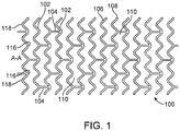
- FIG. 1 illustrates a portion of an exemplary stent or scaffold pattern 100 shown in a flattened view.
- the pattern 100 of FIG. 1 represents a tubular scaffold structure so that a cylindrical axis A-A is parallel to the central or longitudinal axis of the scaffold.
- FIG. 1 shows the scaffold in a state prior to crimping or after deployment.
- Pattern 100 is composed of a plurality of ring struts 102 and link struts 104.
- the ring struts 102 form a plurality of cylindrical rings, for example, rings 106 and 108, arranged about the cylindrical axis A-A.
- the rings have an undulating or sinusoidal structure with alternating crests or peaks 116 and troughs or valleys 118.
- the rings are connected by the link struts 104.
- the scaffold has an open framework of struts and links that define a generally tubular body with gaps 110 in the body defined by rings and struts.
- a cylindrical tube may be formed into this open framework of struts and links by a laser cutting device that cuts such a pattern into a thin-walled tube that may initially have no gaps in the tube wall.
- FIG. 1 The structural pattern in FIG. 1 is merely exemplary and serves to illustrate the basic structure and features of a stent pattern.
- a stent such as stent 100 may be fabricated from a polymeric tube or a sheet by rolling and bonding the sheet to form the tube.
- a tube or sheet can be formed by extrusion or injection molding.
- a stent pattern, such as the one pictured in FIG. 1 can be formed on a tube or sheet with a technique such as laser cutting or chemical etching.
- a bioresorbable scaffold like a metallic stent, is tightly compressed onto a balloon. Plastic deformation of the crimped scaffold induced by the crimping process helps retain that the scaffold on the balloon. Once it is positioned at an implant site, the bioresorbable scaffold is expanded by the balloon. The expansion of the scaffold induces areas of plastic stress in the bioresorbable material to cause the scaffold to achieve and maintain the appropriate diameter on deployment.
- An exemplary scaffold for coronary applications has the stent pattern described in US 2010/0004735 .
- Other examples of stent patterns suitable for bioresorbable polymers are found in US 2008/0275537 , specifically, the pattern depicted in FIG. 15.
- a stent or scaffold delivery system includes a hollow catheter with an inflation lumen.
- a proximal end of the catheter has a catheter hub that connects to an inflation device, which can be an indeflator.
- the distal end of the catheter is connected to a stent-balloon assembly.
- the balloon prior to insertion into a patient, the balloon is in a deflated state in a low profile configuration with the stent crimped thereon.
- the inflation device has access to a source of inflation fluid.
- the inflation device injects inflation fluid into the inflation lumen of the catheter.
- the fluid flows through the inflation lumen into the balloon.
- the pressure therein increases with time, causing the balloon to inflate and expand the stent.
- the balloon is deflated and withdrawn from the implant site, leaving the stent at the implant site apposed against the vessel wall.
- the balloon is deflated by a negative pressure in the inflation lumen imposed by the inflation device which withdraws inflation fluid from the balloon.
- An exemplary inflation device is the 20/30 Indeflator Inflation Device made by Abbott Vascular-Cardiac Therapies of Temecula, CA, USA.
- the indeflator includes a pressure injector at a proximal end and an exit port at a distal end at the tip of a flexible tube that connects to a catheter hub.
- the inflation device has a chamber for holding inflation fluid for injecting into the catheter.
- the inflation device has a pressure gauge that measures the pressure of the injected inflation fluid.
- the inflation fluid may assist a user in visualizing the catheter and balloon during delivery.
- a fluid that is visible to an imaging technique such as x-ray fluoroscopy or magnetic resonance imaging (MRI)
- MRI magnetic resonance imaging
- a contrast agent can include a radiopaque agent or a magnetic resonance imaging agent.
- Radiopaque refers to the ability of a substance to absorb x-rays.
- An MRI agent has a magnetic susceptibility that allows it to be visible with MRI.
- Polymers that are stiff or rigid under conditions within a human body are promising for use as a scaffold material.
- polymers that have a glass transition temperature (Tg) sufficiently above human body temperature should be stiff or rigid upon implantation.
- Tg glass transition temperature
- PLLA poly(L-lactide)
- PLLA-based polymers have relatively high strength and stiffness at human body temperature.
- the advantages of a slower inflation rate during deployment for metallic stents may also apply to bioresorbable scaffolds.
- the inventors have hypothesized that an additional reason for a slower inflation rate for polymer scaffolds or stents is that potential for damage (e.g., fracture, breaking of struts) to a polymer scaffold increases at higher inflation rate.
- susceptibility of a polymer scaffold to damage may be a function of inflation rate.
- the potential for damage to a polymer scaffold at higher inflation rates may be greater than for metal stents.
- Certain polymers may have suitable strength and stiffness properties, however, such polymers tend to have lower ultimate elongation (i.e., elongation at break) or ductility than metals. This potential weakness can be mitigated by a combination of scaffold design and polymer processing. Also, polymers (e.g., PLLA) exhibit viscoelastic behavior where the accumulated stress in the material is a function of the strain history, including the strain rate. Therefore, bioresorbable polymer scaffolds may be more susceptible to strut material damage as the inflation or expansion rate increases.
- the inventors have observed that deployment begins in end rings and propagates toward the middle.
- the inventors hypothesize that high rate of crest opening in the middle increases risk of premature fractures.
- the inventors further hypothesize that employing directional control on inflation will drive overall more consistent deployment speed and eliminate the potential for premature fractures.
- bioresorbable polymer scaffolds may be more susceptible to damage at higher inflation rates.
- Bench tests on bioresorbable scaffolds were performed to evaluate the effect of inflation rate on damage.
- the scaffolds used in the test have a pattern similar to that shown in FIG. 15 of US 2008/0275537 .
- the scaffolds are 3 mm in diameter and 18 mm long.
- the thickness and width of the scaffolds is about 150 microns.
- Detailed discussion of the manufacturing process of the bioresorbable scaffold can be found elsewhere, e.g., U.S. Patent Publication No. 2007/0283552 .
- the test involved moving two parallel pins apart that are disposed within and along the axis of a scaffold. As the pins were extended or moved apart, the load applied to the scaffold was measured as a function of extension of the pins. Four runs were performed at different rates to simulate different inflation rates. A discontinuity in the load vs. extension curves indicates the extension at which failure of ring struts occur. Table 1 below shows the extension at which ring struts fractured for each run. The data is Table 1 shows that as the extension rate increases, the extension at break or fracture of the scaffold decreases. These results imply that damage to a polymer scaffold depends on the inflation rate of a balloon during deployment.
- the inflation rate can be expressed in terms of the pressure of the inflation fluid within the inflation lumen and the balloon, for example, in psi/s.
- Interventional procedures sometimes require a fast inflation of a balloon, stent, or scaffold.
- One reason would be the presence of a coronary perforation. Balloons by themselves, or balloons with scaffolds, are inflated rapidly to hold perforations closed and, hopefully, seal them. The patient may be experiencing other forms of duress such as ischemia induced angina, tachycardia, of fibrillation which pushes the physician to perform the procedure rapidly.
- ischemia induced angina tachycardia
- Embodiments of the present invention include delivery systems that incorporate a pressure attenuator connected to the inflation fluid path that controls the pressure of the inflation fluid.
- the pressure attenuator is in the form of a fluid accumulator.
- the rate of pressure increase or pressurization rate during all or part of the inflation process can be controlled by the accumulator to be within a specified pressurization rate range or below a maximum specified pressurization rate.
- the pressurization rate can controlled all the way up to the maximum deployment pressure, which is the maximum pressure reached during the deployment process.
- the maximum deployment pressure is typically reached when the scaffold deployment is complete and secure in the vessel.
- the pressure control by the accumulator may start only when the pressure exceeds a specified maximum pressure.
- the balloon pressure is not high enough to expand or significantly expand the scaffold.
- the pressurization rate can be higher than the maximum specified pressurization rate.
- the maximum specified pressure may be about 200 kPa (2atm), about 300 kPa (3 atm), about 400 kPa (4 atm), 200 to 400 kPa (2 to 4 atm), 200 to 300 kPa (2 to 3 atm), or 300 - 400 kPa (3 to 4 atm).
- the pressurization rate can be up to 69 kPa/s (10 psi/s), up to 138 kPa/s (20 psi/s), about 207 kPa/s (30 psi/s), 69 to 138 kPa/s (10 to 20 psi/s), or 138 to 207 kPa/s (20 to 30 psi/s).
- the pressurization rate below the maximum specified pressure may be entirely under the control of the operator of the inflation device.
- the average pressurization rate between the maximum specified pressure and the maximum deployment pressure may be controlled to be about 34 kPa/s (5 psi/s), about 41 kPa/s (6 psi/s), about 48 kPa/s (7 psi/s), about 55 kPa/s (8 psi/s), about 69 kPa/s (10 psi/s), 41 to 55 kPa/s (6 to 8 psi/s), 41 to 69 kPa/s (6 to 10 psi/s), 55 to 69 kPa/s (8 to 10 psi /s).
- the instantaneous pressurization rate may also be controlled to within these ranges.
- the maximum deployment pressure can depend on the desired diameter of deployment.
- the maximum pressure may be about 709 kPa (7 atm), about 811 kPa (8 atm), about 1013 kPa (10 atm), about 1216 kPa (12 atm), about 1416 kPa (14 atm), about 1621 kPa (16 atm), 709 to 811 kPa (7 to 8 atm), 811 to 1013 kPa (8 to 10 atm), or 1013 to 1621 kPa (10 to 16 atm).
- the fluid accumulator can be connected to the inflation lumen between the proximal end of the catheter and the delivery balloon. Alternatively, the fluid accumulator can be connected to the inflation device.
- the accumulator may include a fluid chamber or reservoir defined by a structure or part of a structure with containing walls.
- the structure may be a hollow tube.
- the volume of the chamber is variable and increases in response to an increase in pressure of fluid in the chamber. The volume varies due to a section of the containing walls being moveable. The movement of the section is modulated by a biasing element associated with the movable section that applies a biasing force that opposes movement that increases the volume of the chamber.
- the biasing element can be a spring that applies a compression force to the movable section that opposes the force arising from the pressure of the fluid in the chamber.
- An increase in pressure in the chamber causes the movable section to compress the spring, thereby increasing the volume of the chamber and allowing more fluid into the chamber.
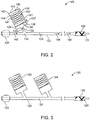
- FIG. 2 depicts a cross-section of a delivery system 120 that incorporates a fluid accumulator 130 for controlling the inflation rate during deployment.
- Delivery system 120 includes a catheter 122 with an inflation lumen 124 through which inflation fluid flows.
- a deflated balloon 125 is connected to a distal end of catheter 122.
- a scaffold 126 is crimped over balloon 125.
- a proximal end of catheter 122 includes a catheter hub 128 that is adapted to be connected to an inflation device (not shown) that is configured to inject inflation fluid into inflation lumen 124 of catheter 122.
- a fluid accumulator 130 is connected to catheter 122 by means of passage way 132. Fluid accumulator 130 is or is capable of fluid communication with inflation lumen 124 through passage way 132.
- a pressure-actuated valve (not shown) can be incorporated in catheter 122, passage way 132, or fluid accumulator 130. The pressure actuated valve allows fluid to enter the chamber only when the pressure of the fluid in the catheter exceeds a specified maximum pressure.
- a body of fluid accumulator 130 can be formed of a hollow tube 141 that includes a chamber 136 at the distal end of tube 141 for holding inflation fluid that flows from inflation lumen 124.
- Chamber 136 is defined by walls 140 of tube 141 and a movable wall or piston 138.
- Piston 138 separates chamber 136 from a compartment 142.
- a spring 144 is disposed within compartment 142.
- a distal end of spring 144 can apply a compression force to piston 138 on a surface opposite to chamber 136, and thus opposes movement of piston 138 is a direction shown by an arrow 137.
- a proximal end of spring 144 can apply a compression force on proximal interior surface 143 of the tube 141.
- an inflation device Prior to deploying stent 126 at an implant site, an inflation device (not shown) is affixed to catheter hub 128. An operator (physician) positions the stent and balloon at an implant site. The operator then manipulates the inflation device to pump inflation fluid into inflation lumen 124 which flows in the direction shown by arrows 148 into balloon 125. As the inflation fluid is injected, the pressure in inflation lumen 124 and balloon 125 increases.
- the control of the pressurization rate of balloon 125 by fluid accumulator 130 can be delayed until for example, the pressure of the inflation fluid reaches a maximum specified value.
- One way of delaying such control is that during an initial time period after injection begins, inflation fluid is prevented from flowing into chamber 136 of fluid accumulator 130. During this time, the rate of injection and pressurization rate are completely controlled by adjustments made by the operator to the inflation device to inject inflation fluid.
- inflation fluid is allowed to flow through passage way 132, as shown by an arrow 133, into chamber 136.
- a pressure actuated valve may prevent flow until the specified maximum pressure is reached and then allow the flow above this pressure.
- the pressure of the inflation fluid in chamber 136 applies a force on piston 138. If the force from the pressure is larger than the opposing compression force of spring 144, piston 138 moves, as shown by arrow 137, which increases the volume of chamber 136.
- the flow of fluid into chamber 136 and the variation in the volume of chamber 136 due to compression of spring 144 by piston 138 control the pressurization rate in catheter 122 and balloon 125.
- the pressurization rate can be controlled by fluid accumulator 130 to be within a specified range or below a specified value. Therefore, above the specified maximum pressure, the pressurization rate depends on the adjustments by the operator and actions of fluid accumulator 130.
- spring 144 may have a nonlinear compression force such that it has a higher or complete resistance to compression below the specified maximum pressure.
- piston 138 may be configured to have a complete resistance or have a higher resistance to movement until the specified maximum pressure is reached.
- Fluid accumulator 130 can control the pressurization rate to be within a specified pressurization rate range or less than a specified pressurization rate. For example, parameters such as the volume of chamber 136 and the compression force of the spring can be selected or adjusted to achieve a desired control of the pressurization rate. The compression force of the spring can be adjusted through selection of the stiffness of the spring. Increasing the volume of the chamber and decreasing the stiffness of the spring will control the pressurization rate to a lower value.
- FIG. 3 depicts a cross-section of a delivery system 150 that incorporates two fluid accumulators 152 and 154 for controlling the inflation rate during deployment.
- the function of each fluid accumulator is as described above.
- Each fluid accumulator can also have a pressure actuated valve.
- the different fluid accumulators can have the same chamber volume and spring constant. The specified maximum pressure of the pressure actuation valves can also be the same. Alternatively, the chamber volumes, spring constants, and specified actuation pressures can be different.
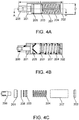
- FIGs. 4A-B depict detailed views of a fluid accumulator.
- FIG. 4A is a side view and FIG. 4B is a cross-sectional view across line A-A.
- FIG. 4C is view of the fluid accumulator with component parts separated from one another.
- the fluid accumulator is composed of a plastic tube 207 with a compression spring 204 disposed within a proximal compartment of plastic tube 207.
- a proximal cap seals the proximal end of tube 207.
- a piston 203 is disposed within the tube distal to compression spring 204.
- a distal cap 201 and an O-Ring 205 seal the distal end of tube 207.
- An adapter 206 disposed within distal cap 201 is configured to connect to the inflation lumen of a catheter.
- FIG. 5 shows the pressure during the deployment as a function of time. The slope of this curve is the pressurization rate. The results showed that the inflation rate was slowed down significantly with the attenuator between about 2 and 8 atm.
Claims (10)
- Un système de déploiement d'un stent comprenant :un ballonnet d'administration (125) ;un stent (126) serti sur le ballonnet d'administration (125) ;un cathéter (122) comprenant une lumière de gonflage (124) en communication fluidique avec le ballonnet d'administration, dans lequel une extrémité proximale du cathéter est adaptée pour être connectée à un dispositif de gonflage, dans lequel la connexion permet l'injection de fluide de gonflage dans la lumière de gonflage du cathéter par le dispositif de gonflage afin de gonfler le ballonnet d'administration ; caractérisé en ce qu'il comprend en outreun dispositif atténuateur de pression (130, 152, 154) pour contrôler un débit de gonflage du ballonnet, comprenant le dispositif atténuateur de pression une chambre (136) connectée avec la lumière de gonflage du cathéter,dans lequel une paroi de pourtour déplaçable (138, 203) de la chambre permet une variation du volume de la chambre en réponse à la pression de fluide de gonflage qui coule de la lumière de gonflage à la chambre, etdans lequel un élément de rappel (144, 204) est associé avec la paroi de pourtour déplaçable pour appliquer une force de rappel s'opposant à une augmentation du volume de la chambre.
- Le système de la revendication 1, dans lequel l'élément de rappel est un ressort et la force de rappel est une force de compression appliquée par le ressort.
- Le système de la revendication 1, dans lequel le dispositif atténuateur de pression est connecté entre l'extrémité proximale du cathéter et le ballonnet d'administration.
- Le système de la revendication 1, comprenant en outre le dispositif de gonflage couplé à une extrémité proximale du cathéter.
- Le système de la revendication 1, dans lequel le dispositif atténuateur de pression comprend un tube (141, 207) et la paroi de pourtour déplaçable est un piston partageant le tube en la chambre et en un compartiment (142) comprenant l'élément de rappel.
- Le système de la revendication 6, comprenant en outre une butée (147) dans le compartiment qui évite un mouvement du piston au-delà de la butée qui augmente le volume de la chambre.
- Le système de la revendication 1, comprenant en outre une soupape actionnée par pression configurée pour permettre l'écoulement du fluide de gonflage de la lumière de gonflage à la chambre seulement lorsque la pression du fluide de gonflage dépasse une pression maximale spécifiée.
- Le système de la revendication 1, comprenant en outre un deuxième dispositif atténuateur de pression (154) en communication fluidique avec la lumière de gonflage entre l'extrémité proximale du cathéter et le ballonnet d'administration.
- Le système de la revendication 8, dans lequel un volume de la chambre du deuxième dispositif atténuateur de pression est différent du volume de la chambre du dispositif atténuateur de pression.
- Le système de la revendication 8, dans lequel une force de rappel du deuxième dispositif atténuateur de pression est différente de la force de rappel du dispositif atténuateur de pression.
Applications Claiming Priority (2)
| Application Number | Priority Date | Filing Date | Title |
|---|---|---|---|
| US13/436,527 US9517151B2 (en) | 2012-03-30 | 2012-03-30 | Control of balloon inflation rate during deployment of scaffold |
| PCT/US2013/034139 WO2013148860A1 (fr) | 2012-03-30 | 2013-03-27 | Commande du taux de gonflage de ballonnet pendant le déploiement d'un échafaudage |
Publications (2)
| Publication Number | Publication Date |
|---|---|
| EP2833844A1 EP2833844A1 (fr) | 2015-02-11 |
| EP2833844B1 true EP2833844B1 (fr) | 2016-12-21 |
Family
ID=48045804
Family Applications (1)
| Application Number | Title | Priority Date | Filing Date |
|---|---|---|---|
| EP13714179.2A Not-in-force EP2833844B1 (fr) | 2012-03-30 | 2013-03-27 | Commande du taux de gonflage de ballonnet pendant le déploiement d'un échafaudage |
Country Status (5)
| Country | Link |
|---|---|
| US (1) | US9517151B2 (fr) |
| EP (1) | EP2833844B1 (fr) |
| JP (1) | JP6219364B2 (fr) |
| HK (1) | HK1206584A1 (fr) |
| WO (1) | WO2013148860A1 (fr) |
Families Citing this family (23)
| Publication number | Priority date | Publication date | Assignee | Title |
|---|---|---|---|---|
| US10022497B2 (en) | 2012-08-28 | 2018-07-17 | Osprey Medical, Inc. | Reservoir for collection and reuse of diverted medium |
| US11116892B2 (en) | 2012-08-28 | 2021-09-14 | Osprey Medical, Inc. | Medium injection diversion and measurement |
| US11219719B2 (en) | 2012-08-28 | 2022-01-11 | Osprey Medical, Inc. | Volume monitoring systems |
| US9320846B2 (en) | 2012-08-28 | 2016-04-26 | Osprey Medical, Inc. | Devices and methods for modulating medium delivery |
| US9999718B2 (en) | 2012-08-28 | 2018-06-19 | Osprey Medical, Inc. | Volume monitoring device utilizing light-based systems |
| US10010673B2 (en) | 2012-08-28 | 2018-07-03 | Osprey Medical, Inc. | Adjustable medium diverter |
| US10413677B2 (en) | 2012-08-28 | 2019-09-17 | Osprey Medical, Inc. | Volume monitoring device |
| JP6378979B2 (ja) * | 2014-09-03 | 2018-08-22 | テルモ株式会社 | 拡張デバイス |
| US9707112B2 (en) * | 2014-09-09 | 2017-07-18 | Mark Conrad Biedebach | Concentric catheter for positioning a polymeric urethral stent implementing resistance heating |
| US10729454B2 (en) | 2014-09-10 | 2020-08-04 | Teleflex Life Sciences Limited | Guidewire capture |
| CN107296638B (zh) | 2014-09-10 | 2020-06-16 | 泰利福生命科学有限公司 | 灌注导管及相关方法 |
| US10231770B2 (en) | 2015-01-09 | 2019-03-19 | Medtronic Holding Company Sárl | Tumor ablation system |
| US10376681B2 (en) | 2016-02-29 | 2019-08-13 | Edwards Lifesciences Corporation | Vacuum-based compliance restoration |
| JP2019511338A (ja) * | 2016-04-12 | 2019-04-25 | セイフ・メディカル・デザイン・インコーポレイテッド | 安全な導尿カテーテル及びその製造方法 |
| US10265111B2 (en) | 2016-04-26 | 2019-04-23 | Medtronic Holding Company Sárl | Inflatable bone tamp with flow control and methods of use |
| US10398484B2 (en) | 2016-06-22 | 2019-09-03 | Medtronic Holding Company Sárl | Inflatable bone tamp with flow control and methods of use |
| US10245050B2 (en) | 2016-09-30 | 2019-04-02 | Teleflex Innovations S.À.R.L. | Methods for facilitating revascularization of occlusion |
| CN107510527A (zh) * | 2017-09-29 | 2017-12-26 | 中山大学附属第医院 | 一种象鼻支架扩张塑形器 |
| US11027102B2 (en) | 2018-07-20 | 2021-06-08 | Teleflex Life Sciences Limited | Perfusion catheters and related methods |
| EP3837000A1 (fr) | 2018-08-16 | 2021-06-23 | Teleflex Life Sciences Limited | Cathéters de perfusion d'élution |
| WO2020210623A1 (fr) | 2019-04-12 | 2020-10-15 | Osprey Medical Inc. | Détermination de position économe en énergie avec de multiples capteurs |
| US11484355B2 (en) | 2020-03-02 | 2022-11-01 | Medtronic Holding Company Sàrl | Inflatable bone tamp and method for use of inflatable bone tamp |
| CN218589504U (zh) * | 2021-04-09 | 2023-03-10 | 爱德华兹生命科学公司 | 带液压减震器的导管系统 |
Family Cites Families (22)
| Publication number | Priority date | Publication date | Assignee | Title |
|---|---|---|---|---|
| US3841319A (en) | 1969-10-20 | 1974-10-15 | T Michael | Method for sealing the oesophagus and providing artificial respiration |
| US5019041A (en) * | 1988-03-08 | 1991-05-28 | Scimed Life Systems, Inc. | Balloon catheter inflation device |
| US5078681A (en) | 1989-10-23 | 1992-01-07 | Olympus Optical Co., Ltd. | Balloon catheter apparatus with releasable distal seal and method of operation |
| WO1995033510A1 (fr) * | 1994-06-07 | 1995-12-14 | Allan Willis | DISPOSITIF DE PROTECTION CONTRE LE SURGONFLAGE DE CATHETER à BALLONNET |
| US5749851A (en) | 1995-03-02 | 1998-05-12 | Scimed Life Systems, Inc. | Stent installation method using balloon catheter having stepped compliance curve |
| US5634910A (en) * | 1995-09-22 | 1997-06-03 | Ryder International Corporation | Syringe instrument |
| US5893868A (en) | 1997-03-05 | 1999-04-13 | Scimed Life Systems, Inc. | Catheter with removable balloon protector and stent delivery system with removable stent protector |
| US5993416A (en) * | 1998-01-15 | 1999-11-30 | Medtronic Ave, Inc. | Method and apparatus for regulating the fluid flow rate to and preventing over-pressurization of a balloon catheter |
| US6547760B1 (en) * | 1998-08-06 | 2003-04-15 | Cardeon Corporation | Aortic catheter with porous aortic arch balloon and methods for selective aortic perfusion |
| GB0011053D0 (en) * | 2000-05-09 | 2000-06-28 | Hudson John O | Medical device and use thereof |
| JP2003535622A (ja) * | 2000-05-09 | 2003-12-02 | ユナイテッド ステーツ エンドスコピー グループ インコーポレイテッド | バレット食道細胞学デバイス |
| US6419657B1 (en) | 2000-08-22 | 2002-07-16 | Advanced Cardiovascular Systems, Inc. | Flow regulator valve to optimize stent deployment and method of using the same |
| US20030078538A1 (en) | 2000-12-28 | 2003-04-24 | Neale Paul V. | Inflation device for dual balloon catheter |
| US20060058866A1 (en) * | 2003-01-17 | 2006-03-16 | Cully Edward H | Deployment system for an expandable device |
| US7537580B2 (en) * | 2004-06-23 | 2009-05-26 | Boston Scientific Scimed, Inc. | Intravascular dilatation infusion catheter |
| US20050288766A1 (en) * | 2004-06-28 | 2005-12-29 | Xtent, Inc. | Devices and methods for controlling expandable prostheses during deployment |
| US7971333B2 (en) | 2006-05-30 | 2011-07-05 | Advanced Cardiovascular Systems, Inc. | Manufacturing process for polymetric stents |
| US7921874B2 (en) | 2004-11-12 | 2011-04-12 | Cook Medical Technologies Llc | Flow variation valve assembly |
| US8002817B2 (en) | 2007-05-04 | 2011-08-23 | Abbott Cardiovascular Systems Inc. | Stents with high radial strength and methods of manufacturing same |
| US8388673B2 (en) | 2008-05-02 | 2013-03-05 | Abbott Cardiovascular Systems Inc. | Polymeric stent |
| US8162902B2 (en) * | 2008-04-04 | 2012-04-24 | Becton, Dickinson And Company | Systems and methods for providing an automatic occlusion device |
| US8708996B2 (en) | 2010-04-30 | 2014-04-29 | Abbott Cardiovascular Systems, Inc. | Methods and device for synergistic mitigation of reperfusion injury after an ischemic event |
-
2012
- 2012-03-30 US US13/436,527 patent/US9517151B2/en active Active
-
2013
- 2013-03-27 EP EP13714179.2A patent/EP2833844B1/fr not_active Not-in-force
- 2013-03-27 WO PCT/US2013/034139 patent/WO2013148860A1/fr active Application Filing
- 2013-03-27 JP JP2015503540A patent/JP6219364B2/ja not_active Expired - Fee Related
-
2015
- 2015-08-04 HK HK15107453.8A patent/HK1206584A1/xx not_active IP Right Cessation
Also Published As
| Publication number | Publication date |
|---|---|
| JP2015516196A (ja) | 2015-06-11 |
| HK1206584A1 (en) | 2016-01-15 |
| US20130261729A1 (en) | 2013-10-03 |
| WO2013148860A1 (fr) | 2013-10-03 |
| EP2833844A1 (fr) | 2015-02-11 |
| JP6219364B2 (ja) | 2017-10-25 |
| US9517151B2 (en) | 2016-12-13 |
Similar Documents
| Publication | Publication Date | Title |
|---|---|---|
| EP2833844B1 (fr) | Commande du taux de gonflage de ballonnet pendant le déploiement d'un échafaudage | |
| JP6344727B2 (ja) | 圧潰復元可能なポリマースキャフォールドの作製方法 | |
| EP2849691B1 (fr) | Vanne de régulation de débit permettant de réguler un taux de gonflage d'un ballonnet déployant un échafaudage | |
| EP3481342B1 (fr) | Système de cathéter pour le traitement de maladies vasculaires et non vasculaires | |
| EP1755485B1 (fr) | Procede et systeme de retenue d'endoprothese a l'aide d'un adhesif | |
| EP1470798B1 (fr) | Méthode pour la rétention d'un stent avec des adhésifs | |
| US9814610B2 (en) | Stent with elongating struts | |
| EP2911622B1 (fr) | Procédé de sertissage de stents biorésorbables | |
| JP2016510625A (ja) | 末梢血管に埋め込まれるスキャフォールドのリコイルの低減 | |
| EP1836998B1 (fr) | Système de mise en place d'une gaine fendue d'endoprothèse vasculaire auto-étendue | |
| WO2016081279A1 (fr) | Dispositif gonflable avec des modifications gravées |
Legal Events
| Date | Code | Title | Description |
|---|---|---|---|
| PUAI | Public reference made under article 153(3) epc to a published international application that has entered the european phase |
Free format text: ORIGINAL CODE: 0009012 |
|
| 17P | Request for examination filed |
Effective date: 20141030 |
|
| AK | Designated contracting states |
Kind code of ref document: A1 Designated state(s): AL AT BE BG CH CY CZ DE DK EE ES FI FR GB GR HR HU IE IS IT LI LT LU LV MC MK MT NL NO PL PT RO RS SE SI SK SM TR |
|
| AX | Request for extension of the european patent |
Extension state: BA ME |
|
| RAP1 | Party data changed (applicant data changed or rights of an application transferred) |
Owner name: ABBOTT CARDIOVASCULAR SYSTEMS INC. |
|
| DAX | Request for extension of the european patent (deleted) | ||
| REG | Reference to a national code |
Ref country code: HK Ref legal event code: DE Ref document number: 1206584 Country of ref document: HK |
|
| GRAP | Despatch of communication of intention to grant a patent |
Free format text: ORIGINAL CODE: EPIDOSNIGR1 |
|
| INTG | Intention to grant announced |
Effective date: 20160630 |
|
| GRAS | Grant fee paid |
Free format text: ORIGINAL CODE: EPIDOSNIGR3 |
|
| GRAA | (expected) grant |
Free format text: ORIGINAL CODE: 0009210 |
|
| AK | Designated contracting states |
Kind code of ref document: B1 Designated state(s): AL AT BE BG CH CY CZ DE DK EE ES FI FR GB GR HR HU IE IS IT LI LT LU LV MC MK MT NL NO PL PT RO RS SE SI SK SM TR |
|
| REG | Reference to a national code |
Ref country code: GB Ref legal event code: FG4D |
|
| REG | Reference to a national code |
Ref country code: CH Ref legal event code: EP |
|
| REG | Reference to a national code |
Ref country code: IE Ref legal event code: FG4D |
|
| REG | Reference to a national code |
Ref country code: AT Ref legal event code: REF Ref document number: 854820 Country of ref document: AT Kind code of ref document: T Effective date: 20170115 |
|
| REG | Reference to a national code |
Ref country code: DE Ref legal event code: R096 Ref document number: 602013015579 Country of ref document: DE |
|
| PG25 | Lapsed in a contracting state [announced via postgrant information from national office to epo] |
Ref country code: LV Free format text: LAPSE BECAUSE OF FAILURE TO SUBMIT A TRANSLATION OF THE DESCRIPTION OR TO PAY THE FEE WITHIN THE PRESCRIBED TIME-LIMIT Effective date: 20161221 |
|
| REG | Reference to a national code |
Ref country code: NL Ref legal event code: FP |
|
| REG | Reference to a national code |
Ref country code: LT Ref legal event code: MG4D |
|
| PG25 | Lapsed in a contracting state [announced via postgrant information from national office to epo] |
Ref country code: GR Free format text: LAPSE BECAUSE OF FAILURE TO SUBMIT A TRANSLATION OF THE DESCRIPTION OR TO PAY THE FEE WITHIN THE PRESCRIBED TIME-LIMIT Effective date: 20170322 Ref country code: NO Free format text: LAPSE BECAUSE OF FAILURE TO SUBMIT A TRANSLATION OF THE DESCRIPTION OR TO PAY THE FEE WITHIN THE PRESCRIBED TIME-LIMIT Effective date: 20170321 Ref country code: SE Free format text: LAPSE BECAUSE OF FAILURE TO SUBMIT A TRANSLATION OF THE DESCRIPTION OR TO PAY THE FEE WITHIN THE PRESCRIBED TIME-LIMIT Effective date: 20161221 Ref country code: LT Free format text: LAPSE BECAUSE OF FAILURE TO SUBMIT A TRANSLATION OF THE DESCRIPTION OR TO PAY THE FEE WITHIN THE PRESCRIBED TIME-LIMIT Effective date: 20161221 |
|
| REG | Reference to a national code |
Ref country code: AT Ref legal event code: MK05 Ref document number: 854820 Country of ref document: AT Kind code of ref document: T Effective date: 20161221 |
|
| PG25 | Lapsed in a contracting state [announced via postgrant information from national office to epo] |
Ref country code: FI Free format text: LAPSE BECAUSE OF FAILURE TO SUBMIT A TRANSLATION OF THE DESCRIPTION OR TO PAY THE FEE WITHIN THE PRESCRIBED TIME-LIMIT Effective date: 20161221 Ref country code: HR Free format text: LAPSE BECAUSE OF FAILURE TO SUBMIT A TRANSLATION OF THE DESCRIPTION OR TO PAY THE FEE WITHIN THE PRESCRIBED TIME-LIMIT Effective date: 20161221 Ref country code: RS Free format text: LAPSE BECAUSE OF FAILURE TO SUBMIT A TRANSLATION OF THE DESCRIPTION OR TO PAY THE FEE WITHIN THE PRESCRIBED TIME-LIMIT Effective date: 20161221 |
|
| PG25 | Lapsed in a contracting state [announced via postgrant information from national office to epo] |
Ref country code: RO Free format text: LAPSE BECAUSE OF FAILURE TO SUBMIT A TRANSLATION OF THE DESCRIPTION OR TO PAY THE FEE WITHIN THE PRESCRIBED TIME-LIMIT Effective date: 20161221 Ref country code: IS Free format text: LAPSE BECAUSE OF FAILURE TO SUBMIT A TRANSLATION OF THE DESCRIPTION OR TO PAY THE FEE WITHIN THE PRESCRIBED TIME-LIMIT Effective date: 20170421 Ref country code: SK Free format text: LAPSE BECAUSE OF FAILURE TO SUBMIT A TRANSLATION OF THE DESCRIPTION OR TO PAY THE FEE WITHIN THE PRESCRIBED TIME-LIMIT Effective date: 20161221 Ref country code: CZ Free format text: LAPSE BECAUSE OF FAILURE TO SUBMIT A TRANSLATION OF THE DESCRIPTION OR TO PAY THE FEE WITHIN THE PRESCRIBED TIME-LIMIT Effective date: 20161221 Ref country code: EE Free format text: LAPSE BECAUSE OF FAILURE TO SUBMIT A TRANSLATION OF THE DESCRIPTION OR TO PAY THE FEE WITHIN THE PRESCRIBED TIME-LIMIT Effective date: 20161221 |
|
| PG25 | Lapsed in a contracting state [announced via postgrant information from national office to epo] |
Ref country code: BG Free format text: LAPSE BECAUSE OF FAILURE TO SUBMIT A TRANSLATION OF THE DESCRIPTION OR TO PAY THE FEE WITHIN THE PRESCRIBED TIME-LIMIT Effective date: 20170321 Ref country code: BE Free format text: LAPSE BECAUSE OF FAILURE TO SUBMIT A TRANSLATION OF THE DESCRIPTION OR TO PAY THE FEE WITHIN THE PRESCRIBED TIME-LIMIT Effective date: 20161221 Ref country code: SM Free format text: LAPSE BECAUSE OF FAILURE TO SUBMIT A TRANSLATION OF THE DESCRIPTION OR TO PAY THE FEE WITHIN THE PRESCRIBED TIME-LIMIT Effective date: 20161221 Ref country code: PT Free format text: LAPSE BECAUSE OF FAILURE TO SUBMIT A TRANSLATION OF THE DESCRIPTION OR TO PAY THE FEE WITHIN THE PRESCRIBED TIME-LIMIT Effective date: 20170421 Ref country code: AT Free format text: LAPSE BECAUSE OF FAILURE TO SUBMIT A TRANSLATION OF THE DESCRIPTION OR TO PAY THE FEE WITHIN THE PRESCRIBED TIME-LIMIT Effective date: 20161221 Ref country code: ES Free format text: LAPSE BECAUSE OF FAILURE TO SUBMIT A TRANSLATION OF THE DESCRIPTION OR TO PAY THE FEE WITHIN THE PRESCRIBED TIME-LIMIT Effective date: 20161221 Ref country code: PL Free format text: LAPSE BECAUSE OF FAILURE TO SUBMIT A TRANSLATION OF THE DESCRIPTION OR TO PAY THE FEE WITHIN THE PRESCRIBED TIME-LIMIT Effective date: 20161221 Ref country code: IT Free format text: LAPSE BECAUSE OF FAILURE TO SUBMIT A TRANSLATION OF THE DESCRIPTION OR TO PAY THE FEE WITHIN THE PRESCRIBED TIME-LIMIT Effective date: 20161221 |
|
| REG | Reference to a national code |
Ref country code: DE Ref legal event code: R097 Ref document number: 602013015579 Country of ref document: DE |
|
| REG | Reference to a national code |
Ref country code: HK Ref legal event code: GR Ref document number: 1206584 Country of ref document: HK |
|
| PLBE | No opposition filed within time limit |
Free format text: ORIGINAL CODE: 0009261 |
|
| STAA | Information on the status of an ep patent application or granted ep patent |
Free format text: STATUS: NO OPPOSITION FILED WITHIN TIME LIMIT |
|
| REG | Reference to a national code |
Ref country code: CH Ref legal event code: PL |
|
| 26N | No opposition filed |
Effective date: 20170922 |
|
| PG25 | Lapsed in a contracting state [announced via postgrant information from national office to epo] |
Ref country code: DK Free format text: LAPSE BECAUSE OF FAILURE TO SUBMIT A TRANSLATION OF THE DESCRIPTION OR TO PAY THE FEE WITHIN THE PRESCRIBED TIME-LIMIT Effective date: 20161221 Ref country code: MC Free format text: LAPSE BECAUSE OF FAILURE TO SUBMIT A TRANSLATION OF THE DESCRIPTION OR TO PAY THE FEE WITHIN THE PRESCRIBED TIME-LIMIT Effective date: 20161221 |
|
| REG | Reference to a national code |
Ref country code: FR Ref legal event code: ST Effective date: 20171130 |
|
| PG25 | Lapsed in a contracting state [announced via postgrant information from national office to epo] |
Ref country code: LU Free format text: LAPSE BECAUSE OF NON-PAYMENT OF DUE FEES Effective date: 20170327 Ref country code: FR Free format text: LAPSE BECAUSE OF NON-PAYMENT OF DUE FEES Effective date: 20170331 |
|
| PG25 | Lapsed in a contracting state [announced via postgrant information from national office to epo] |
Ref country code: SI Free format text: LAPSE BECAUSE OF FAILURE TO SUBMIT A TRANSLATION OF THE DESCRIPTION OR TO PAY THE FEE WITHIN THE PRESCRIBED TIME-LIMIT Effective date: 20161221 Ref country code: CH Free format text: LAPSE BECAUSE OF NON-PAYMENT OF DUE FEES Effective date: 20170331 Ref country code: LI Free format text: LAPSE BECAUSE OF NON-PAYMENT OF DUE FEES Effective date: 20170331 |
|
| PG25 | Lapsed in a contracting state [announced via postgrant information from national office to epo] |
Ref country code: MT Free format text: LAPSE BECAUSE OF NON-PAYMENT OF DUE FEES Effective date: 20170327 |
|
| PG25 | Lapsed in a contracting state [announced via postgrant information from national office to epo] |
Ref country code: HU Free format text: LAPSE BECAUSE OF FAILURE TO SUBMIT A TRANSLATION OF THE DESCRIPTION OR TO PAY THE FEE WITHIN THE PRESCRIBED TIME-LIMIT; INVALID AB INITIO Effective date: 20130327 |
|
| PG25 | Lapsed in a contracting state [announced via postgrant information from national office to epo] |
Ref country code: CY Free format text: LAPSE BECAUSE OF FAILURE TO SUBMIT A TRANSLATION OF THE DESCRIPTION OR TO PAY THE FEE WITHIN THE PRESCRIBED TIME-LIMIT Effective date: 20161221 |
|
| PG25 | Lapsed in a contracting state [announced via postgrant information from national office to epo] |
Ref country code: MK Free format text: LAPSE BECAUSE OF FAILURE TO SUBMIT A TRANSLATION OF THE DESCRIPTION OR TO PAY THE FEE WITHIN THE PRESCRIBED TIME-LIMIT Effective date: 20161221 |
|
| PG25 | Lapsed in a contracting state [announced via postgrant information from national office to epo] |
Ref country code: TR Free format text: LAPSE BECAUSE OF FAILURE TO SUBMIT A TRANSLATION OF THE DESCRIPTION OR TO PAY THE FEE WITHIN THE PRESCRIBED TIME-LIMIT Effective date: 20161221 |
|
| PGFP | Annual fee paid to national office [announced via postgrant information from national office to epo] |
Ref country code: DE Payment date: 20200214 Year of fee payment: 8 Ref country code: GB Payment date: 20200228 Year of fee payment: 8 Ref country code: NL Payment date: 20200227 Year of fee payment: 8 Ref country code: IE Payment date: 20200225 Year of fee payment: 8 |
|
| PG25 | Lapsed in a contracting state [announced via postgrant information from national office to epo] |
Ref country code: AL Free format text: LAPSE BECAUSE OF FAILURE TO SUBMIT A TRANSLATION OF THE DESCRIPTION OR TO PAY THE FEE WITHIN THE PRESCRIBED TIME-LIMIT Effective date: 20161221 |
|
| REG | Reference to a national code |
Ref country code: DE Ref legal event code: R119 Ref document number: 602013015579 Country of ref document: DE |
|
| REG | Reference to a national code |
Ref country code: NL Ref legal event code: MM Effective date: 20210401 |
|
| GBPC | Gb: european patent ceased through non-payment of renewal fee |
Effective date: 20210327 |
|
| PG25 | Lapsed in a contracting state [announced via postgrant information from national office to epo] |
Ref country code: NL Free format text: LAPSE BECAUSE OF NON-PAYMENT OF DUE FEES Effective date: 20210401 Ref country code: DE Free format text: LAPSE BECAUSE OF NON-PAYMENT OF DUE FEES Effective date: 20211001 Ref country code: IE Free format text: LAPSE BECAUSE OF NON-PAYMENT OF DUE FEES Effective date: 20210327 Ref country code: GB Free format text: LAPSE BECAUSE OF NON-PAYMENT OF DUE FEES Effective date: 20210327 |