EP2833519A2 - A stator winding arrangement for an electrical machine - Google Patents
A stator winding arrangement for an electrical machine Download PDFInfo
- Publication number
- EP2833519A2 EP2833519A2 EP14177275.6A EP14177275A EP2833519A2 EP 2833519 A2 EP2833519 A2 EP 2833519A2 EP 14177275 A EP14177275 A EP 14177275A EP 2833519 A2 EP2833519 A2 EP 2833519A2
- Authority
- EP
- European Patent Office
- Prior art keywords
- winding
- windings
- short
- phase
- stator
- Prior art date
- Legal status (The legal status is an assumption and is not a legal conclusion. Google has not performed a legal analysis and makes no representation as to the accuracy of the status listed.)
- Granted
Links
- 238000004804 winding Methods 0.000 title claims abstract description 148
- 230000004907 flux Effects 0.000 claims abstract description 6
- 230000010363 phase shift Effects 0.000 description 10
- 238000010438 heat treatment Methods 0.000 description 5
- 238000010079 rubber tapping Methods 0.000 description 4
- 230000001360 synchronised effect Effects 0.000 description 4
- 239000004020 conductor Substances 0.000 description 3
- 238000010586 diagram Methods 0.000 description 3
- 230000005540 biological transmission Effects 0.000 description 2
- 230000001143 conditioned effect Effects 0.000 description 2
- 230000003071 parasitic effect Effects 0.000 description 2
- 230000002457 bidirectional effect Effects 0.000 description 1
- 230000003750 conditioning effect Effects 0.000 description 1
- 238000001816 cooling Methods 0.000 description 1
- 230000001419 dependent effect Effects 0.000 description 1
- 230000008030 elimination Effects 0.000 description 1
- 238000003379 elimination reaction Methods 0.000 description 1
- 230000010355 oscillation Effects 0.000 description 1
Images


Classifications
-
- H—ELECTRICITY
- H02—GENERATION; CONVERSION OR DISTRIBUTION OF ELECTRIC POWER
- H02K—DYNAMO-ELECTRIC MACHINES
- H02K3/00—Details of windings
- H02K3/04—Windings characterised by the conductor shape, form or construction, e.g. with bar conductors
-
- H—ELECTRICITY
- H02—GENERATION; CONVERSION OR DISTRIBUTION OF ELECTRIC POWER
- H02K—DYNAMO-ELECTRIC MACHINES
- H02K3/00—Details of windings
- H02K3/04—Windings characterised by the conductor shape, form or construction, e.g. with bar conductors
- H02K3/28—Layout of windings or of connections between windings
-
- H—ELECTRICITY
- H02—GENERATION; CONVERSION OR DISTRIBUTION OF ELECTRIC POWER
- H02K—DYNAMO-ELECTRIC MACHINES
- H02K1/00—Details of the magnetic circuit
- H02K1/06—Details of the magnetic circuit characterised by the shape, form or construction
- H02K1/12—Stationary parts of the magnetic circuit
- H02K1/16—Stator cores with slots for windings
-
- H—ELECTRICITY
- H02—GENERATION; CONVERSION OR DISTRIBUTION OF ELECTRIC POWER
- H02K—DYNAMO-ELECTRIC MACHINES
- H02K21/00—Synchronous motors having permanent magnets; Synchronous generators having permanent magnets
- H02K21/12—Synchronous motors having permanent magnets; Synchronous generators having permanent magnets with stationary armatures and rotating magnets
-
- H—ELECTRICITY
- H02—GENERATION; CONVERSION OR DISTRIBUTION OF ELECTRIC POWER
- H02K—DYNAMO-ELECTRIC MACHINES
- H02K3/00—Details of windings
- H02K3/46—Fastening of windings on the stator or rotor structure
- H02K3/48—Fastening of windings on the stator or rotor structure in slots
-
- H—ELECTRICITY
- H02—GENERATION; CONVERSION OR DISTRIBUTION OF ELECTRIC POWER
- H02M—APPARATUS FOR CONVERSION BETWEEN AC AND AC, BETWEEN AC AND DC, OR BETWEEN DC AND DC, AND FOR USE WITH MAINS OR SIMILAR POWER SUPPLY SYSTEMS; CONVERSION OF DC OR AC INPUT POWER INTO SURGE OUTPUT POWER; CONTROL OR REGULATION THEREOF
- H02M7/00—Conversion of ac power input into dc power output; Conversion of dc power input into ac power output
-
- H—ELECTRICITY
- H02—GENERATION; CONVERSION OR DISTRIBUTION OF ELECTRIC POWER
- H02K—DYNAMO-ELECTRIC MACHINES
- H02K11/00—Structural association of dynamo-electric machines with electric components or with devices for shielding, monitoring or protection
- H02K11/04—Structural association of dynamo-electric machines with electric components or with devices for shielding, monitoring or protection for rectification
- H02K11/049—Rectifiers associated with stationary parts, e.g. stator cores
- H02K11/05—Rectifiers associated with casings, enclosures or brackets
-
- H—ELECTRICITY
- H02—GENERATION; CONVERSION OR DISTRIBUTION OF ELECTRIC POWER
- H02K—DYNAMO-ELECTRIC MACHINES
- H02K3/00—Details of windings
- H02K3/04—Windings characterised by the conductor shape, form or construction, e.g. with bar conductors
- H02K3/12—Windings characterised by the conductor shape, form or construction, e.g. with bar conductors arranged in slots
-
- Y—GENERAL TAGGING OF NEW TECHNOLOGICAL DEVELOPMENTS; GENERAL TAGGING OF CROSS-SECTIONAL TECHNOLOGIES SPANNING OVER SEVERAL SECTIONS OF THE IPC; TECHNICAL SUBJECTS COVERED BY FORMER USPC CROSS-REFERENCE ART COLLECTIONS [XRACs] AND DIGESTS
- Y02—TECHNOLOGIES OR APPLICATIONS FOR MITIGATION OR ADAPTATION AGAINST CLIMATE CHANGE
- Y02E—REDUCTION OF GREENHOUSE GAS [GHG] EMISSIONS, RELATED TO ENERGY GENERATION, TRANSMISSION OR DISTRIBUTION
- Y02E10/00—Energy generation through renewable energy sources
- Y02E10/70—Wind energy
- Y02E10/72—Wind turbines with rotation axis in wind direction
Definitions
- This invention relates to a winding arrangement for an electrical machine.
- the invention relates to a stator winding for a synchronous machine which is driven in use by a variable speed prime mover.
- the invention finds particular utility where electrical power is provided to a network or load via a 12 pulse rectifier arrangement.
- Permanent Magnet, PM, electrical machines provide robust and compact motors and generators in many industries, such as aerospace for powers up to several 10's of kW's and marine propulsion systems and wind turbine plants up to and potentially above 5MW.
- the fixed magnets located on the rotor of a PM machine result in a rotating magnetic field having a constant magnitude.
- the magnitude and frequency of the generated output voltage varies with the rotor speed.
- the rotor speed will be generally controlled by and proportional to the speed of the gas turbine jet engine and the drive shaft taken from one of the spools. In current applications, this speed may vary during a flight cycle by as much as 10:1 which relates to significant changes in voltage and frequency beyond acceptable limits for many applications. Consequently, the variable voltage and frequency is conditioned by a fully rated AC to DC converter which is arranged to produce a constant DC voltage by controlling the reactive power flow in the machine stator windings.
- FIG. 1 shows a typical drive arrangement 10 for providing a DC voltage from a PM machine.
- a machine rotor 12 which carries a permanent magnet 14 and which is driveably connected to a prime mover, for example a gas turbine engine via an appropriate transmission (not shown).
- the rotor 12 is rotatably located within the stator 16 of the machine such that a voltage is induced in the stator windings upon rotation of the permanent magnet.
- the stator is electrically connected to and outputs current to an active convertor 18 which is operated to provide a constant DC voltage 20 for a load (not shown).
- FIG. 2 shows an electrical system 210 which includes a PM machine 12 which outputs a current to a 6-pulse diode rectifier 214 and single transistor DC to DC converter 216.
- the 6-pulse diode rectifier 214 converts the variable magnitude, variable frequency voltage provided by the PM machine 212 to a variable magnitude direct voltage. This is conditioned by the DC to DC convertor 216 to provide a constant direct voltage to a direct voltage 218 power bus.
- the inductor 220 shown as part of the DC to DC convertor can be effectively replaced in favour of the PM machine stator windings.
- US7595612 provides an example of a drive similar to that shown in Figure 2 .
- a drawback with the simple arrangement shown in Figure 2 is that the use of a 6 pulse rectifier introduces significant levels of 5th and 7th harmonic currents into the system and stator windings. These currents are parasitic in that they do not contribute to the useful electrical power generated and create additional heating in the stator windings, thereby reducing the current carrying capacity. Further, the harmonic currents cause eddy current heating in the permanent magnets of the rotor and create additional torque oscillations in the mechanical drive train.
- the arrangement 310 shown in Figure 3a includes a star-delta (YD) stator winding 314 arrangement to provide the two channels 316a,b which are 30 degrees out of phase with one another.
- the two channels 316a,b are connected to respective 6 pulse diode rectifiers 318a,b which each feed respective loads 320a,b.
- the 5 th and 7 th harmonic currents can be calculated and analysed after an FFT analysis and also measuring the Total Harmonic Distortion (THD)
- TDD Total Harmonic Distortion
- the 30 degree phase shift provided by the YD windings 314 results in the 5th and 7th harmonic currents being out of phase so as to largely cancel out one another within the stator. This reduces rotor eddy current heating and the torque ripple seen by the rotor.
- the YD stator windings 314 are overly complex and do not address the additional current flow in the windings which still suffer from parasitic power dissipation as a result of the 5th and 7th harmonics.
- the present invention seeks to provide an improved PM machine for DC systems.
- the present invention provides an electrical system comprising an electrical machine, comprising: a rotor having a magnetic flux source mounted thereto; a stator winding arrangement having a first set of electrical connections to provide a first output channel, and a second set of electrical connections to provide a second output channel, the first and second channels being electrically out of phase, wherein the stator winding arrangement is constructed from a plurality of winding portions connected in electrical series, wherein each output channel is connected to a load or network.
- stator winding which is tapped at various points to provide a plurality of winding portions allows a two channel machine to be provided in a compact way with fewer losses than known systems.
- the winding portions may comprise a plurality of alternately connected long and short windings.
- the output channels may be poly phase and the short windings may provide the phase difference between the two output channels in that each phase of the first channel is taken from one end of a short winding.
- Each phase of the second channel may be taken from the respective other end of the short winding.
- the first and second output channels may be approximately 30 degrees out of phase.
- a third channel may be taken from the midpoint of the short winding for each phase.
- the stator may include slots and turns of each long winding may be located in the same slot as turns of at least one short winding. All of the stator slots of a stator pole may be occupied by both the long and short windings.
- the long and short windings may be arranged around the stator such that the circumferential pole length of the long and short windings are the same.
- the magnetic flux source may be a permanent magnet.
- the stator winding arrangement may be three phase.
- the electrical machine may have three or more output channels.
- Each channel may be connected to the load or network via a DC convertor.
- the invention provides an aircraft, marine vessel or wind turbine having the electrical machine or the electrical system of the preceding aspects.
- Figure 4 shows a schematic representation of an electrical machine 410 in the form of a synchronous machine which is driven by a variable speed drive.
- the machine in this instance is a permanent magnet machine and as such produces an electrical output having variable magnitude and frequency which is dependent on the speed of the drive, as described above.
- the electrical machine 410 has two electrical outputs or channels 412a,b which are electrically offset from one another. That is, the electrical outputs are electrically out of phase by a predetermined amount.
- the determination of the degree of phase shift between the channels 412a,b is described in detail below with reference to Figure 6 , but is generally provided by having an electrical machine 410 including a rotor 414 having a magnetic flux source mounted thereto; a stator winding arrangement 418 having a first set of electrical connections R1, Y1, B1, to provide the first output channel 412a and a second set of electrical connections R2, Y2, B2, to provide the second output channel 412b in which the first 412a and second 412b channels are electrically out of phase.
- the stator winding arrangement 418 is constructed from a plurality of winding portions which are connected in electrical series to provide a plurality of electrical tapping points between adjacent winding portions. The winding portions are arranged such that the tapping points provide two phase sets.
- the phase connections in a given phase set are equally distributed about the stator winding so as to be (in the three phase case) 120 degrees out of phase, with each phase set being 30 degrees out of phase.
- FIG. 4 there is a three phase stator winding 418 which can provide a first phase set of electrical connections R1, Y1, B1 which are placed at 0, 120 and 240 degrees around the winding 418, and a second set R2, Y2, B2 which are placed at 30, 150 and 270 degrees, with the 0 and 30, 120 and 150, and 240 and 270 connection points each nominally representing the respective red R1, R2, yellow, Y1, Y2, and blue B1, B2, phases of each channel 412a,b.
- a polyphase stator winding arrangement having a plurality of serially connected windings arranged to provide n phases, where in each phase includes at least two electrical terminals which are electrically offset from one another by a predetermined and equal amount so as to provide the electrical machine with 2n phases sets which are electrically out of phase from each other.
- the electrical machine 410 finds particular utility for providing an electrical generating system which provides power to DC convertors which suffer from 5 th and 7 th harmonic current distortions as described above.
- the two electrical channels 412a,b are connected to two six diode bridge rectifier 424a,b and convertor 426a,b arrangements which rectify the alternating current outputted from the PM machine 410 into DC which is the passed through a basic chopper circuit for adjusting the magnitude of the output DC voltage.
- Other arrangements of rectifying convertor arrangement are possible and other areas of application for the two channel machine are envisaged within the scope of the invention.
- the invention is particularly advantageous as it provides a machine having low harmonic current distortion in the dominant stator windings, low levels of induced eddy current flow in the rotor and reduced torque ripple on the mechanical drive train which provides torque to the rotor.
- the improvement in stator and rotor current waveforms will lead to less localised heating and therefore the requirement for less cooling.
- the stator windings 418 are made up from a plurality of long and short windings 422R,r,Y,y,B,b, which are connected in electrical series and arranged so as to provide a 30 degree phase shift across the short windings 422r,y,b.
- the stator arrangement is three phase, with each phase being represented by a short 422r,y,b and a long 422R,Y,B winding, with the two being opposite one another as shown in Figure 4 .
- Figure 4 shows the electrical connection of the windings 422R,r,Y,y,B,b.
- providing a physical series connection of windings 422R,r,Y,y,B,b around the stator in this way in a practical machine is not desirable because of the large harmonics that would arise in the air-gap due to the stator's space harmonics.
- turns of the long winding 422R,Y,B are associated with and in the same slot as turns of the short winding 422r,y,b.
- the windings of a pole may partially overlap or fully overlap around the stator pole pitch. Where there is a partial overlap, it is necessary to ensure that the mid-point of the long and short windings are co-located with respect to the stator. This will ensure that the voltages in the long and short windings are in phase with one another.
- all six slots may be occupied by turns of the long winding, with the middle two additionally occupied by the short windings. In this way, the mid-points of the long and short windings are co-located with each other and the mid-point of the pole.
- a preferred embodiment includes both the long and short windings being common to all of the slots of a given pole to reduce the space harmonics.
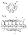
- Figure 5a shows a schematic representation of a stator 510 in axial section having circumferentially distributed slots 512(1-18) for the windings 522R,r,Y,y,B,b arranged around a rotor.
- Figure 5b shows a corresponding windings 522R,r,Y,y,B,b for the stator slots 512 of Figure 5a .
- Figure 5b represents the stator 510 in an unwrapped state so as to more readily show the arrangement of the individual windings 522R,r,Y,y,B,b.
- a two pole machine having a stator 510 which includes eighteen slots 512 evenly distributed around the circumference of the machine. This provides three slots per pole per phase.
- the selection of a two pole machine is for illustration only and should not be taken to limit the scope of the invention.
- the long windings 522R,Y,B are shown above the slots 512, the short windings 522r,y,b below with the +/- signs depicting the direction of the winding direction in which + indicates the winding is travelling out of the paper as shown, whilst - indicates the winding travelling into the paper.
- R, Y and B denote the long windings and r, y, b denote the short windings.
- Both the long 522R,Y,B and the short 522r,y,b windings are distributed windings and the connections between the phases are such that it provides the polygonal arrangement shown in Figure 4 .
- the connections between the windings 522R,r,Y,y,B,b are not shown in Figure 5b for the sake of clarity but the skilled person will appreciate that from an analysis of the two drawings that slots 1 and 10 are partially filled with turns of the red phase long winding 522R before slots 2 and 11, and then 3 and 12 are partially filled to provide a distributed pole.
- the extent of filling in each case is determined by multiple factors including the number of turns required, conductor size and available filling factor etc. This will be application specific and determined at least in part by the required phase shift required across each of the short windings.
- FIG. 4 shows a polygon winding arrangement 418 according to the invention.
- a three phase winding having nominal red, yellow and blue phases.
- Each of the phases includes a long 422R,Y,B and short 422r,y,b winding which are physically arranged within the stator 418 as described above.
- the phase vector diagram for one of the electrically adjacent long 422R,Y,B and short 422r,y,b windings is shown in Figure 6a and Figure 6b .
- ⁇ is the phase shift required across the short winding 422r,y,b.
- setting ⁇ to a predetermined amount, 30 degrees in the described embodiment provides the required turns ratio for the long 422R,Y,B and short 422r,y,b windings via n.
- the short windings 422r,y,b have approximately a third of the turns of the long windings 422 R,Y, B.
- the difference in the winding lengths and the voltages leads to different currents flowing through the long windings 422R,Y,B relative to the short windings 422r,y,b. It has been shown in one exemplary machine that the power provided from the long windings 422R,Y,B was 47.75kW and the power from the short windings 422r,y,b was 13.21kW, making the total power from machine 60.96kW. Thus, the short windings 422r,y,b provided 27.6% of the power of the long windings 422R,Y,B whilst having 36.6% of the voltage due to the different electrical length of the windings.
- Figure 7 shows electrical voltage and current wave forms for the long and short winding with the respective 12 pulse currents being shown on each.
- the 5 th and 7 th harmonic currents in the short and long winding correspondingly will be out of phase (30 degrees) and thus largely cancelling one another within the stator winding.
- the elimination of the 5 th and 7 th harmonic current could be analysed after FFT analysis of the current waveforms.
- the invention provides a relatively compact winding arrangement for an electrical machine which can provide output waveforms which are substantially free of 5 th and 7 th harmonic currents.
- the voltages and currents in both the long and short windings are in phase, meaning that there is no reactive power within these windings, therefore less losses, less heating effort and also reduced power rate of the machine.
- the compact nature of the machine can be further increased in embodiments where the rectifier and convertor are co-located within the electrical machine, thus providing a DC generator which requires minimal electronic control circuitry.
- Figure 8 shows an 18 pulse electrical machine 810 in which the stator windings 818 provide three channels 812a-c, which are 20 degrees out of phase from one another.
- the three channels are provided by tapping the windings at either end of the short windings 822r,y,b and a mid-point as illustrated.
- the Total Harmonic Distortion is reduced using the 18 pulse polygon but the power rating of PM machine is higher as there is a small phase shift between voltages and currents in the short windings. This results in some reactive power flow.
- Other embodiments, such as 24 pulse machines are also envisaged.
- the electrical machine described in the above examples is a permanent magnetic machine.
- the invention may be applied to other suitable electrical machines where appropriate.
- the invention may find application in a wound field synchronous machine.
- the present invention is particularly advantageous to applications having variable speed drives, it may be applicable in scenarios which utilise a constant speed prime mover.
- the phase shift of 30 degrees and 20 degrees achieved across the windings should be taken as approximate. A phase shift which achieves significant cancellation of the 5 th and 7 th harmonics in 12 and 24 pulse machines respectively is considered to be within the scope of the claims.
Abstract
Description
- This invention relates to a winding arrangement for an electrical machine. In particular, the invention relates to a stator winding for a synchronous machine which is driven in use by a variable speed prime mover. The invention finds particular utility where electrical power is provided to a network or load via a 12 pulse rectifier arrangement.
- Permanent Magnet, PM, electrical machines provide robust and compact motors and generators in many industries, such as aerospace for powers up to several 10's of kW's and marine propulsion systems and wind turbine plants up to and potentially above 5MW.
- The fixed magnets located on the rotor of a PM machine result in a rotating magnetic field having a constant magnitude. This means that the magnitude and frequency of the generated output voltage varies with the rotor speed. In aerospace applications, the rotor speed will be generally controlled by and proportional to the speed of the gas turbine jet engine and the drive shaft taken from one of the spools. In current applications, this speed may vary during a flight cycle by as much as 10:1 which relates to significant changes in voltage and frequency beyond acceptable limits for many applications. Consequently, the variable voltage and frequency is conditioned by a fully rated AC to DC converter which is arranged to produce a constant DC voltage by controlling the reactive power flow in the machine stator windings.
- In marine propulsion systems shaft generators driven by the main propulsion engine(s) to provide electrical power are limited by the fact that the ship's electrical system normally requires a fixed frequency. This means that engine speed has to be kept constant which is generally inefficient. The use of a power electronics converter in a marine electrical network has the benefit that the main engine can operate at an optimum speed to maximise its efficiency, effectively decoupling it from the requirement to operate at fixed speed to support the fixed frequency marine electrical network.
-
Figure 1 shows atypical drive arrangement 10 for providing a DC voltage from a PM machine. Thus, there is depicted amachine rotor 12 which carries apermanent magnet 14 and which is driveably connected to a prime mover, for example a gas turbine engine via an appropriate transmission (not shown). Therotor 12 is rotatably located within thestator 16 of the machine such that a voltage is induced in the stator windings upon rotation of the permanent magnet. The stator is electrically connected to and outputs current to anactive convertor 18 which is operated to provide aconstant DC voltage 20 for a load (not shown). - In many applications, the PM machine is only required to act as an electrical power generator in which case the fully active, bidirectional converter as shown in
Figure 1 is unnecessary and a simpler unidirectional conditioning scheme can be used.Figure 2 shows anelectrical system 210 which includes aPM machine 12 which outputs a current to a 6-pulse diode rectifier 214 and single transistor DC toDC converter 216. Here the 6-pulse diode rectifier 214 converts the variable magnitude, variable frequency voltage provided by the PM machine 212 to a variable magnitude direct voltage. This is conditioned by the DC toDC convertor 216 to provide a constant direct voltage to adirect voltage 218 power bus. It will be appreciated that in some applications, theinductor 220 shown as part of the DC to DC convertor can be effectively replaced in favour of the PM machine stator windings.US7595612 provides an example of a drive similar to that shown inFigure 2 . - A drawback with the simple arrangement shown in
Figure 2 is that the use of a 6 pulse rectifier introduces significant levels of 5th and 7th harmonic currents into the system and stator windings. These currents are parasitic in that they do not contribute to the useful electrical power generated and create additional heating in the stator windings, thereby reducing the current carrying capacity. Further, the harmonic currents cause eddy current heating in the permanent magnets of the rotor and create additional torque oscillations in the mechanical drive train. - It is known that providing a 12-pulse system can help reduce the 5th and 7th harmonic currents in the PM machine. A two channel approach is known to construct 12-pulse transformer-rectifier system in high power electrical power transmission and distribution systems, and a similar approach may be applicable to a PM machine. Another known configuration is a 6 pulse synchronous system achieved by connecting the stator windings in a star and delta configuration which provides two channels electrically displaced 30 degrees.
- The
arrangement 310 shown inFigure 3a includes a star-delta (YD) stator winding 314 arrangement to provide the twochannels 316a,b which are 30 degrees out of phase with one another. The twochannels 316a,b are connected to respective 6pulse diode rectifiers 318a,b which each feedrespective loads 320a,b. The 5th and 7th harmonic currents can be calculated and analysed after an FFT analysis and also measuring the Total Harmonic Distortion (THD) As can be seen fromFigure 3b , the 30 degree phase shift provided by theYD windings 314 results in the 5th and 7th harmonic currents being out of phase so as to largely cancel out one another within the stator. This reduces rotor eddy current heating and the torque ripple seen by the rotor. - Although this provides an improvement over the PM machine with conventional stator windings, the
YD stator windings 314 are overly complex and do not address the additional current flow in the windings which still suffer from parasitic power dissipation as a result of the 5th and 7th harmonics. - The present invention seeks to provide an improved PM machine for DC systems.
- The present invention provides an electrical system comprising an electrical machine, comprising: a rotor having a magnetic flux source mounted thereto; a stator winding arrangement having a first set of electrical connections to provide a first output channel, and a second set of electrical connections to provide a second output channel, the first and second channels being electrically out of phase, wherein the stator winding arrangement is constructed from a plurality of winding portions connected in electrical series, wherein each output channel is connected to a load or network.
- Having a stator winding which is tapped at various points to provide a plurality of winding portions allows a two channel machine to be provided in a compact way with fewer losses than known systems.
- The winding portions may comprise a plurality of alternately connected long and short windings.
- The output channels may be poly phase and the short windings may provide the phase difference between the two output channels in that each phase of the first channel is taken from one end of a short winding. Each phase of the second channel may be taken from the respective other end of the short winding.
- The first and second output channels may be approximately 30 degrees out of phase.
- A third channel may be taken from the midpoint of the short winding for each phase.
- The stator may include slots and turns of each long winding may be located in the same slot as turns of at least one short winding. All of the stator slots of a stator pole may be occupied by both the long and short windings. The long and short windings may be arranged around the stator such that the circumferential pole length of the long and short windings are the same.
- The magnetic flux source may be a permanent magnet.
- The stator winding arrangement may be three phase.
- The electrical machine may have three or more output channels.
- Each channel may be connected to the load or network via a DC convertor.
- In a yet further aspect, the invention provides an aircraft, marine vessel or wind turbine having the electrical machine or the electrical system of the preceding aspects.
- Embodiments of the invention will now be described with the aid of the following drawings in which:
-
Figure 1 shows a typical drive arrangement for providing a DC voltage from a PM machine. -
Figure 2 shows an electrical system which includes a PM machine which outputs a current to a 6-pulse diode rectifier and single transistor DC to DC converter. -
Figure 3a shows a PM machine with a star-delta winding arrangement which provides two channels which are 30 degrees out of phase. -
Figure 3b shows the voltage waveforms for the star and delta windings with the respective 6 pulse current harmonics. -
Figures 4 shows a schematic diagram of an electrical machine according to the present invention. -
Figures 5a and 5b show an axial section of a 2 pole electrical machine and the associated winding arrangement. -
Figures 6a and 6b show the phasor arrangement of the windings. -
Figure 7 shows the voltages and currents of both the long and short windings (12 pulse winding arrangement) within the stator winding arrangement for an exemplary machine. -
Figure 8 shows the implementation of the invention to provide an 18 pulse electrical machine. -
Figure 4 shows a schematic representation of an electrical machine 410 in the form of a synchronous machine which is driven by a variable speed drive. The machine in this instance is a permanent magnet machine and as such produces an electrical output having variable magnitude and frequency which is dependent on the speed of the drive, as described above. - In order to provide a constant electrical output for a network or load, the electrical machine 410 has two electrical outputs or
channels 412a,b which are electrically offset from one another. That is, the electrical outputs are electrically out of phase by a predetermined amount. - The determination of the degree of phase shift between the
channels 412a,b is described in detail below with reference toFigure 6 , but is generally provided by having an electrical machine 410 including arotor 414 having a magnetic flux source mounted thereto; astator winding arrangement 418 having a first set of electrical connections R1, Y1, B1, to provide thefirst output channel 412a and a second set of electrical connections R2, Y2, B2, to provide thesecond output channel 412b in which the first 412a and second 412b channels are electrically out of phase. Thestator winding arrangement 418 is constructed from a plurality of winding portions which are connected in electrical series to provide a plurality of electrical tapping points between adjacent winding portions. The winding portions are arranged such that the tapping points provide two phase sets. The phase connections in a given phase set are equally distributed about the stator winding so as to be (in the three phase case) 120 degrees out of phase, with each phase set being 30 degrees out of phase. - Thus, as shown in
Figure 4 , there is a three phase stator winding 418 which can provide a first phase set of electrical connections R1, Y1, B1 which are placed at 0, 120 and 240 degrees around the winding 418, and a second set R2, Y2, B2 which are placed at 30, 150 and 270 degrees, with the 0 and 30, 120 and 150, and 240 and 270 connection points each nominally representing the respective red R1, R2, yellow, Y1, Y2, and blue B1, B2, phases of eachchannel 412a,b. - More generally, there is provided a polyphase stator winding arrangement having a plurality of serially connected windings arranged to provide n phases, where in each phase includes at least two electrical terminals which are electrically offset from one another by a predetermined and equal amount so as to provide the electrical machine with 2n phases sets which are electrically out of phase from each other.
- The electrical machine 410 finds particular utility for providing an electrical generating system which provides power to DC convertors which suffer from 5th and 7th harmonic current distortions as described above. Thus, in the described embodiment, the two
electrical channels 412a,b are connected to two sixdiode bridge rectifier 424a,b andconvertor 426a,b arrangements which rectify the alternating current outputted from the PM machine 410 into DC which is the passed through a basic chopper circuit for adjusting the magnitude of the output DC voltage. Other arrangements of rectifying convertor arrangement are possible and other areas of application for the two channel machine are envisaged within the scope of the invention. - The invention is particularly advantageous as it provides a machine having low harmonic current distortion in the dominant stator windings, low levels of induced eddy current flow in the rotor and reduced torque ripple on the mechanical drive train which provides torque to the rotor. The improvement in stator and rotor current waveforms will lead to less localised heating and therefore the requirement for less cooling.
- The
stator windings 418 are made up from a plurality of long andshort windings 422R,r,Y,y,B,b, which are connected in electrical series and arranged so as to provide a 30 degree phase shift across theshort windings 422r,y,b. The stator arrangement is three phase, with each phase being represented by a short 422r,y,b and a long 422R,Y,B winding, with the two being opposite one another as shown inFigure 4 . -
Figure 4 shows the electrical connection of thewindings 422R,r,Y,y,B,b. However, providing a physical series connection ofwindings 422R,r,Y,y,B,b around the stator in this way in a practical machine is not desirable because of the large harmonics that would arise in the air-gap due to the stator's space harmonics. Rather, it is preferable to distribute the turns of the short winding 422r,y,b equally across the slots of its associated long winding 422R,Y,B to reduce the space harmonics. In this way turns of the long winding 422R,Y,B are associated with and in the same slot as turns of the short winding 422r,y,b. - The windings of a pole may partially overlap or fully overlap around the stator pole pitch. Where there is a partial overlap, it is necessary to ensure that the mid-point of the long and short windings are co-located with respect to the stator. This will ensure that the voltages in the long and short windings are in phase with one another. Hence, in a stator having six slots per pole, all six slots may be occupied by turns of the long winding, with the middle two additionally occupied by the short windings. In this way, the mid-points of the long and short windings are co-located with each other and the mid-point of the pole. As shown below, a preferred embodiment includes both the long and short windings being common to all of the slots of a given pole to reduce the space harmonics.
-
Figure 5a shows a schematic representation of astator 510 in axial section having circumferentially distributed slots 512(1-18) for the windings 522R,r,Y,y,B,b arranged around a rotor.Figure 5b shows a corresponding windings 522R,r,Y,y,B,b for thestator slots 512 ofFigure 5a . Hence,Figure 5b represents thestator 510 in an unwrapped state so as to more readily show the arrangement of the individual windings 522R,r,Y,y,B,b. - In the described embodiment a two pole machine is shown having a
stator 510 which includes eighteenslots 512 evenly distributed around the circumference of the machine. This provides three slots per pole per phase. The selection of a two pole machine is for illustration only and should not be taken to limit the scope of the invention. - With reference to
Figure 5b the long windings 522R,Y,B are shown above theslots 512, theshort windings 522r,y,b below with the +/- signs depicting the direction of the winding direction in which + indicates the winding is travelling out of the paper as shown, whilst - indicates the winding travelling into the paper. R, Y and B denote the long windings and r, y, b denote the short windings. - Both the long 522R,Y,B and the short 522r,y,b windings are distributed windings and the connections between the phases are such that it provides the polygonal arrangement shown in
Figure 4 . The connections between the windings 522R,r,Y,y,B,b are not shown inFigure 5b for the sake of clarity but the skilled person will appreciate that from an analysis of the two drawings thatslots 1 and 10 are partially filled with turns of the red phase long winding 522R beforeslots respective slots 512. As will be appreciated, the extent of filling in each case is determined by multiple factors including the number of turns required, conductor size and available filling factor etc. This will be application specific and determined at least in part by the required phase shift required across each of the short windings. - Once the distributed windings are in place for each of the long 522R,Y,B and short 522r,y,b windings and for each phase there will be two conductor ends per winding which are connected to provide the polygonal winding arrangement shown in
Figure 4 , with appropriate tapping points for terminal connections. Hence, one end of the red phase short winding 522r inslot 3 is connected to the end of the yellow phase long winding 522Y inslot 4, and the other end of the yellow phase long winding 522Y inslot 6 is connected with the adjacent end of the blue phase short winding 522B in slot 7 and so on. The outputs for R1 and R2 shown onFigure 4 are taken from the connection betweenslots 1 and 4, andslots - To provide the necessary phase shift between the ends of the short windings (and long windings) whilst having the windings in the same slots requires the windings to have the necessary relative electrical length. In order to do this, the number of turns for the long and short windings are selected to provide a desired voltage ratio. The equations set out below and explained with reference to
Figures 6a and 6b can be used to determine the necessary ratio. -
Figure 4 shows apolygon winding arrangement 418 according to the invention. Thus, there is provided a three phase winding having nominal red, yellow and blue phases. Each of the phases includes a long 422R,Y,B and short 422r,y,b winding which are physically arranged within thestator 418 as described above. The phase vector diagram for one of the electrically adjacent long 422R,Y,B and short 422r,y,b windings is shown inFigure 6a and Figure 6b . Hence, from the polygon vector diagram:
- With the polygon long winding 422R,Y,B voltage being defined by:

- And the polygon short winding 422r,y,b voltage being defined by:

- From the polygon vector drawing it can be found that:

- And so for a turns ratio given by


- Where ϕ is the phase shift required across the short winding 422r,y,b. Hence, setting ϕ to a predetermined amount, 30 degrees in the described embodiment, provides the required turns ratio for the long 422R,Y,B and short 422r,y,b windings via n. For a phase shift of approximately 30 degrees, the
short windings 422r,y,b have approximately a third of the turns of thelong windings 422 R,Y, B. - The difference in the winding lengths and the voltages leads to different currents flowing through the
long windings 422R,Y,B relative to theshort windings 422r,y,b. It has been shown in one exemplary machine that the power provided from thelong windings 422R,Y,B was 47.75kW and the power from theshort windings 422r,y,b was 13.21kW, making the total power from machine 60.96kW. Thus, theshort windings 422r,y,b provided 27.6% of the power of thelong windings 422R,Y,B whilst having 36.6% of the voltage due to the different electrical length of the windings. This results in a short winding 422r,y,b current flow of around three-quarters of that in the long winding 422R,Y,B. This means the short winding 422r,y,b can be made from thinner section conductor whilst operating at the same current density as the long winding 422R,Y,B. -
Figure 7 shows electrical voltage and current wave forms for the long and short winding with the respective 12 pulse currents being shown on each. As a result of the 12 pulse winding arrangement the 5th and 7th harmonic currents in the short and long winding correspondingly will be out of phase (30 degrees) and thus largely cancelling one another within the stator winding. The elimination of the 5th and 7th harmonic current could be analysed after FFT analysis of the current waveforms. Thus, the invention provides a relatively compact winding arrangement for an electrical machine which can provide output waveforms which are substantially free of 5th and 7th harmonic currents. It will also be noted that the voltages and currents in both the long and short windings are in phase, meaning that there is no reactive power within these windings, therefore less losses, less heating effort and also reduced power rate of the machine. The compact nature of the machine can be further increased in embodiments where the rectifier and convertor are co-located within the electrical machine, thus providing a DC generator which requires minimal electronic control circuitry. - The principles of the invention can be extended to cover other embodiments. For example,
Figure 8 shows an 18 pulseelectrical machine 810 in which thestator windings 818 provide threechannels 812a-c, which are 20 degrees out of phase from one another. The three channels are provided by tapping the windings at either end of theshort windings 822r,y,b and a mid-point as illustrated. The Total Harmonic Distortion is reduced using the 18 pulse polygon but the power rating of PM machine is higher as there is a small phase shift between voltages and currents in the short windings. This results in some reactive power flow. Other embodiments, such as 24 pulse machines are also envisaged. - The electrical machine described in the above examples is a permanent magnetic machine. However, it will be appreciated that the invention may be applied to other suitable electrical machines where appropriate. For example, the invention may find application in a wound field synchronous machine. Further, although the present invention is particularly advantageous to applications having variable speed drives, it may be applicable in scenarios which utilise a constant speed prime mover. It will also be appreciated, that the phase shift of 30 degrees and 20 degrees achieved across the windings should be taken as approximate. A phase shift which achieves significant cancellation of the 5th and 7th harmonics in 12 and 24 pulse machines respectively is considered to be within the scope of the claims.
Claims (13)
- An electrical system comprising:an electrical machine (410), having:a rotor (414) having a magnetic flux source (416) mounted thereto;a stator winding arrangement (418) having a first set of electrical connections to provide a first output channel (412a), and a second set of electrical connections to provide a second output channel (412b), the first and second channels (412a,b) being electrically out of phase,wherein the stator winding (418) arrangement is constructed from a plurality of winding portions (422R,r,Y,y,B,b) connected in electrical series,wherein each output channel is connected to a load or network.
- An electrical system as claimed in claim 1 wherein the winding portions (422R,r,Y,y,B,b) comprise a plurality of alternately connected long (422R,Y,B) and short (422r,y,b) windings.
- An electrical system as claimed in claim 2, wherein the output channels are polyphase and the short windings (422r,y,b) provide the phase difference between the two output channels in that each phase of the first channel is taken from one end of a short winding (422r,y,b), and each phase of the second channel is taken from the respective other end of the short winding (422r,y,b).
- An electrical system as claimed in any preceding claim wherein the first and second output channels are approximately 30 degrees out of phase.
- An electrical system as claimed in any of claims 2 to 4, further comprising a third channel which is taken from the midpoint of the short winding (422r,y,b) for each phase.
- An electrical system as claimed in any of claims 2 to 5, wherein the long (422R,Y,B) and short (422r,y,b) windings are arranged around the stator such that the mid-point of the windings are located at the mid-point of a stator pole.
- An electrical system as claimed in any of claims 2 to 6, wherein the stator (510) includes slots (512(1-18)) and turns of each long (522R,Y,B) winding are located in the same slot (512(1-18)) as turns of at least one short winding (522r,y,b).
- An electrical system as claimed in claim 7, wherein all of the stator slots of a stator pole include turns of both the long and short windings.
- An electrical system as claimed in any preceding claim wherein the magnetic flux source (416) is a permanent magnet.
- An electrical system as claimed in any preceding claim wherein the stator winding arrangement is three phase.
- An electrical system as claimed in any preceding claim having three or more output channels.
- An electrical system as claimed in any preceding claim, wherein each channel is connected to the load or network via a DC convertor.
- An aircraft, marine vessel or wind turbine having the electrical system of claims 1 to 12.
Applications Claiming Priority (1)
| Application Number | Priority Date | Filing Date | Title |
|---|---|---|---|
| GBGB1313684.1A GB201313684D0 (en) | 2013-07-31 | 2013-07-31 | A stator winding arrangement for an electrical machine |
Publications (3)
| Publication Number | Publication Date |
|---|---|
| EP2833519A2 true EP2833519A2 (en) | 2015-02-04 |
| EP2833519A3 EP2833519A3 (en) | 2016-05-25 |
| EP2833519B1 EP2833519B1 (en) | 2018-01-10 |
Family
ID=49167248
Family Applications (1)
| Application Number | Title | Priority Date | Filing Date |
|---|---|---|---|
| EP14177275.6A Active EP2833519B1 (en) | 2013-07-31 | 2014-07-16 | A stator winding arrangement for an electrical machine |
Country Status (3)
| Country | Link |
|---|---|
| US (1) | US9853512B2 (en) |
| EP (1) | EP2833519B1 (en) |
| GB (1) | GB201313684D0 (en) |
Cited By (1)
| Publication number | Priority date | Publication date | Assignee | Title |
|---|---|---|---|---|
| AT521291B1 (en) * | 2018-05-15 | 2021-04-15 | Maketronic E U | SYNCHRONOUS MOTOR |
Families Citing this family (7)
| Publication number | Priority date | Publication date | Assignee | Title |
|---|---|---|---|---|
| US10693408B2 (en) * | 2014-07-29 | 2020-06-23 | Dana Tm4 Inc. | Multiple phase electric machine, drive and control |
| US9641112B2 (en) * | 2014-12-10 | 2017-05-02 | Clark Equipment Company | Protection method for a generator |
| US9847687B2 (en) * | 2015-03-16 | 2017-12-19 | Caterpillar Inc. | Multiphase induction motor with flux weakening |
| GB2549086B (en) | 2016-03-30 | 2022-09-07 | Advanced Electric Machines Group Ltd | Electrical sub-assembly |
| US10651770B2 (en) | 2018-08-29 | 2020-05-12 | Hamilton Sundstrand Corporation | Direct current voltage regulation of a six-phase permanent magnet generator |
| US10778127B2 (en) * | 2018-09-10 | 2020-09-15 | Hamilton Sundstrand Corporation | Direct current voltage regulation of permanent magnet generator |
| US10855216B2 (en) | 2018-09-10 | 2020-12-01 | Hamilton Sundstrand Corporation | Voltage regulation of multi-phase permanent magnet generator |
Family Cites Families (22)
| Publication number | Priority date | Publication date | Assignee | Title |
|---|---|---|---|---|
| GB330790A (en) | 1928-10-10 | 1930-06-19 | Naamlooze Vennootschap Hengelo | Improvements in asynchronous motors |
| JPS5357415A (en) * | 1976-11-02 | 1978-05-24 | Mitsubishi Electric Corp | Solid commutator motor device |
| WO2006065988A2 (en) * | 2004-12-13 | 2006-06-22 | Borealis Technical Limited | Motor winding |
| CA2238504C (en) * | 1997-05-26 | 2001-03-13 | Atsushi Umeda | Stator arrangement of alternator for vehicle |
| JP3384337B2 (en) * | 1998-09-07 | 2003-03-10 | 株式会社デンソー | Stator of vehicle alternator |
| JP3621635B2 (en) * | 2000-08-10 | 2005-02-16 | 三菱電機株式会社 | Rotating electric machine |
| JP3948009B2 (en) * | 2001-10-03 | 2007-07-25 | 株式会社安川電機 | Winding switching device for three-phase AC motor |
| WO2004051828A1 (en) * | 2002-12-05 | 2004-06-17 | Linear Propulsion Motor Company (Pty) Ltd | A motor |
| US6995546B2 (en) * | 2004-04-29 | 2006-02-07 | Shindaiwa Kogyo Co., Ltd. | Alternating current generator |
| US6940202B1 (en) * | 2004-05-19 | 2005-09-06 | Visteon Global Technologies, Inc. | Electrical machine having a stator winding with a plurality of filars |
| JP4339757B2 (en) * | 2004-07-12 | 2009-10-07 | 株式会社日立製作所 | Vehicle drive power generation system |
| US7075206B1 (en) | 2005-02-07 | 2006-07-11 | Visteon Global Technologies, Inc. | Vehicle alternator stator winding having dual slot configuration |
| DE502006000995D1 (en) * | 2005-03-31 | 2008-08-07 | Alstom Technology Ltd | GENERATOR WITH HIGH PHASE ORDER |
| JP4617992B2 (en) * | 2005-04-28 | 2011-01-26 | トヨタ自動車株式会社 | Winding structure of rotating electrical machine |
| JP4654068B2 (en) * | 2005-05-24 | 2011-03-16 | 日立オートモティブシステムズ株式会社 | Bonded electric wire, method of processing the bonded electric wire, rotating electric machine stator, rotating electric machine stator manufacturing method, and bonded electric wire manufacturing apparatus |
| DE102005063271A1 (en) * | 2005-12-30 | 2007-07-19 | Robert Bosch Gmbh | Generator, in particular for motor vehicles |
| US7388300B2 (en) * | 2006-09-20 | 2008-06-17 | Honeywell International, Inc. | Starter-generator operable with multiple variable frequencies and voltages |
| US7710081B2 (en) * | 2006-10-27 | 2010-05-04 | Direct Drive Systems, Inc. | Electromechanical energy conversion systems |
| US7595612B2 (en) * | 2007-05-21 | 2009-09-29 | Honeywell International Inc. | Wide speed range electric power generation system using high reactance permanent magnet machine |
| US7939959B2 (en) * | 2008-06-30 | 2011-05-10 | General Electric Company | Wind turbine with parallel converters utilizing a plurality of isolated transformer windings |
| CN103762811B (en) * | 2008-06-30 | 2017-04-12 | 株式会社美姿把 | Electric motor |
| CN202068252U (en) | 2011-05-11 | 2011-12-07 | 高玉森 | Special variable-torque rare-earth permanent magnet motor for pumping unit |
-
2013
- 2013-07-31 GB GBGB1313684.1A patent/GB201313684D0/en not_active Ceased
-
2014
- 2014-07-16 EP EP14177275.6A patent/EP2833519B1/en active Active
- 2014-07-16 US US14/332,879 patent/US9853512B2/en active Active
Cited By (1)
| Publication number | Priority date | Publication date | Assignee | Title |
|---|---|---|---|---|
| AT521291B1 (en) * | 2018-05-15 | 2021-04-15 | Maketronic E U | SYNCHRONOUS MOTOR |
Also Published As
| Publication number | Publication date |
|---|---|
| GB201313684D0 (en) | 2013-09-11 |
| US20150035395A1 (en) | 2015-02-05 |
| US9853512B2 (en) | 2017-12-26 |
| EP2833519B1 (en) | 2018-01-10 |
| EP2833519A3 (en) | 2016-05-25 |
Similar Documents
| Publication | Publication Date | Title |
|---|---|---|
| EP2833519B1 (en) | A stator winding arrangement for an electrical machine | |
| US7615904B2 (en) | Brushless high-frequency alternator and excitation method for three-phase AC power-frequency generation | |
| US8076814B2 (en) | Brushless high-frequency alternator and excitation method for DC, single-phase and multi-phase AC power-frequency generation | |
| EP2149964B1 (en) | Synchronous generator and synchronous generator system | |
| US20150349687A1 (en) | Electric Power Generation and Distribution for Islanded or Weakly-Connected Systems | |
| US10033302B2 (en) | Rotary solar converter | |
| US9742331B2 (en) | Doubly-fed, variable-speed, dual-voltage AC generation and distribution systems | |
| US9680344B2 (en) | Multiphase electrical machine and method of use | |
| WO2002035689A1 (en) | High phase order motor with mesh connected windings | |
| RU2010141915A (en) | POWER DISTRIBUTION SYSTEM | |
| Xiong et al. | Design and performance analysis of a brushless doubly-fed machine for stand-alone ship shaft generator systems | |
| US7990115B2 (en) | High frequency generator without rotating diode rectifier | |
| JPH0865976A (en) | Brushless self-excited three-phase synchronous generator | |
| Vizireanu et al. | Polyphased modular direct-drive wind turbine generator | |
| Schreier et al. | Effect of combined stator winding on reduction of higher spatial harmonics in induction machine | |
| Beik et al. | High voltage generator for wind turbines | |
| Beik et al. | A brushless exciter design for a hybrid permanent magnet generator applied to series hybrid electric vehicles | |
| Tessarolo | Experimental performance assessment of multiphase alternators supplying multiple AC/DC power converters | |
| Schreier et al. | Analysis of IM with combined six-phase configuration of stator phase windings with respect to higher spatial harmonics | |
| US20230170753A1 (en) | Generator common core winding | |
| Koptjaev et al. | A New Brushless Generator with Nonsalient Poles | |
| Ahmed et al. | Reduction of cogging torque and back EMF harmonics in modulated pole machine by variations in tooth span | |
| JP5349258B2 (en) | Power generator for distributed power supply | |
| RU2617713C2 (en) | High-speed small marine gen-set | |
| RU2636053C2 (en) | Method of generation of ac voltages of two different frequencies in three-phase current turbo-generator |
Legal Events
| Date | Code | Title | Description |
|---|---|---|---|
| 17P | Request for examination filed |
Effective date: 20140716 |
|
| AK | Designated contracting states |
Kind code of ref document: A2 Designated state(s): AL AT BE BG CH CY CZ DE DK EE ES FI FR GB GR HR HU IE IS IT LI LT LU LV MC MK MT NL NO PL PT RO RS SE SI SK SM TR |
|
| AX | Request for extension of the european patent |
Extension state: BA ME |
|
| PUAI | Public reference made under article 153(3) epc to a published international application that has entered the european phase |
Free format text: ORIGINAL CODE: 0009012 |
|
| RAP1 | Party data changed (applicant data changed or rights of an application transferred) |
Owner name: ROLLS-ROYCE PLC |
|
| PUAL | Search report despatched |
Free format text: ORIGINAL CODE: 0009013 |
|
| RIC1 | Information provided on ipc code assigned before grant |
Ipc: H02K 3/28 20060101AFI20160411BHEP |
|
| AK | Designated contracting states |
Kind code of ref document: A3 Designated state(s): AL AT BE BG CH CY CZ DE DK EE ES FI FR GB GR HR HU IE IS IT LI LT LU LV MC MK MT NL NO PL PT RO RS SE SI SK SM TR |
|
| AX | Request for extension of the european patent |
Extension state: BA ME |
|
| RIC1 | Information provided on ipc code assigned before grant |
Ipc: H02K 3/28 20060101AFI20160418BHEP |
|
| R17P | Request for examination filed (corrected) |
Effective date: 20161124 |
|
| RBV | Designated contracting states (corrected) |
Designated state(s): AL AT BE BG CH CY CZ DE DK EE ES FI FR GB GR HR HU IE IS IT LI LT LU LV MC MK MT NL NO PL PT RO RS SE SI SK SM TR |
|
| GRAP | Despatch of communication of intention to grant a patent |
Free format text: ORIGINAL CODE: EPIDOSNIGR1 |
|
| INTG | Intention to grant announced |
Effective date: 20170802 |
|
| GRAS | Grant fee paid |
Free format text: ORIGINAL CODE: EPIDOSNIGR3 |
|
| GRAA | (expected) grant |
Free format text: ORIGINAL CODE: 0009210 |
|
| AK | Designated contracting states |
Kind code of ref document: B1 Designated state(s): AL AT BE BG CH CY CZ DE DK EE ES FI FR GB GR HR HU IE IS IT LI LT LU LV MC MK MT NL NO PL PT RO RS SE SI SK SM TR |
|
| REG | Reference to a national code |
Ref country code: CH Ref legal event code: EP Ref country code: AT Ref legal event code: REF Ref document number: 963456 Country of ref document: AT Kind code of ref document: T Effective date: 20180115 |
|
| REG | Reference to a national code |
Ref country code: IE Ref legal event code: FG4D |
|
| REG | Reference to a national code |
Ref country code: DE Ref legal event code: R096 Ref document number: 602014019607 Country of ref document: DE |
|
| REG | Reference to a national code |
Ref country code: NL Ref legal event code: MP Effective date: 20180110 |
|
| REG | Reference to a national code |
Ref country code: AT Ref legal event code: MK05 Ref document number: 963456 Country of ref document: AT Kind code of ref document: T Effective date: 20180110 |
|
| PG25 | Lapsed in a contracting state [announced via postgrant information from national office to epo] |
Ref country code: NL Free format text: LAPSE BECAUSE OF FAILURE TO SUBMIT A TRANSLATION OF THE DESCRIPTION OR TO PAY THE FEE WITHIN THE PRESCRIBED TIME-LIMIT Effective date: 20180110 |
|
| REG | Reference to a national code |
Ref country code: FR Ref legal event code: PLFP Year of fee payment: 5 |
|
| PG25 | Lapsed in a contracting state [announced via postgrant information from national office to epo] |
Ref country code: FI Free format text: LAPSE BECAUSE OF FAILURE TO SUBMIT A TRANSLATION OF THE DESCRIPTION OR TO PAY THE FEE WITHIN THE PRESCRIBED TIME-LIMIT Effective date: 20180110 Ref country code: CY Free format text: LAPSE BECAUSE OF FAILURE TO SUBMIT A TRANSLATION OF THE DESCRIPTION OR TO PAY THE FEE WITHIN THE PRESCRIBED TIME-LIMIT Effective date: 20180110 Ref country code: ES Free format text: LAPSE BECAUSE OF FAILURE TO SUBMIT A TRANSLATION OF THE DESCRIPTION OR TO PAY THE FEE WITHIN THE PRESCRIBED TIME-LIMIT Effective date: 20180110 Ref country code: LT Free format text: LAPSE BECAUSE OF FAILURE TO SUBMIT A TRANSLATION OF THE DESCRIPTION OR TO PAY THE FEE WITHIN THE PRESCRIBED TIME-LIMIT Effective date: 20180110 Ref country code: HR Free format text: LAPSE BECAUSE OF FAILURE TO SUBMIT A TRANSLATION OF THE DESCRIPTION OR TO PAY THE FEE WITHIN THE PRESCRIBED TIME-LIMIT Effective date: 20180110 Ref country code: NO Free format text: LAPSE BECAUSE OF FAILURE TO SUBMIT A TRANSLATION OF THE DESCRIPTION OR TO PAY THE FEE WITHIN THE PRESCRIBED TIME-LIMIT Effective date: 20180410 |
|
| PG25 | Lapsed in a contracting state [announced via postgrant information from national office to epo] |
Ref country code: BG Free format text: LAPSE BECAUSE OF FAILURE TO SUBMIT A TRANSLATION OF THE DESCRIPTION OR TO PAY THE FEE WITHIN THE PRESCRIBED TIME-LIMIT Effective date: 20180410 Ref country code: RS Free format text: LAPSE BECAUSE OF FAILURE TO SUBMIT A TRANSLATION OF THE DESCRIPTION OR TO PAY THE FEE WITHIN THE PRESCRIBED TIME-LIMIT Effective date: 20180110 Ref country code: AT Free format text: LAPSE BECAUSE OF FAILURE TO SUBMIT A TRANSLATION OF THE DESCRIPTION OR TO PAY THE FEE WITHIN THE PRESCRIBED TIME-LIMIT Effective date: 20180110 Ref country code: LV Free format text: LAPSE BECAUSE OF FAILURE TO SUBMIT A TRANSLATION OF THE DESCRIPTION OR TO PAY THE FEE WITHIN THE PRESCRIBED TIME-LIMIT Effective date: 20180110 Ref country code: SE Free format text: LAPSE BECAUSE OF FAILURE TO SUBMIT A TRANSLATION OF THE DESCRIPTION OR TO PAY THE FEE WITHIN THE PRESCRIBED TIME-LIMIT Effective date: 20180110 Ref country code: PL Free format text: LAPSE BECAUSE OF FAILURE TO SUBMIT A TRANSLATION OF THE DESCRIPTION OR TO PAY THE FEE WITHIN THE PRESCRIBED TIME-LIMIT Effective date: 20180110 Ref country code: IS Free format text: LAPSE BECAUSE OF FAILURE TO SUBMIT A TRANSLATION OF THE DESCRIPTION OR TO PAY THE FEE WITHIN THE PRESCRIBED TIME-LIMIT Effective date: 20180510 Ref country code: GR Free format text: LAPSE BECAUSE OF FAILURE TO SUBMIT A TRANSLATION OF THE DESCRIPTION OR TO PAY THE FEE WITHIN THE PRESCRIBED TIME-LIMIT Effective date: 20180411 |
|
| REG | Reference to a national code |
Ref country code: DE Ref legal event code: R097 Ref document number: 602014019607 Country of ref document: DE |
|
| PG25 | Lapsed in a contracting state [announced via postgrant information from national office to epo] |
Ref country code: EE Free format text: LAPSE BECAUSE OF FAILURE TO SUBMIT A TRANSLATION OF THE DESCRIPTION OR TO PAY THE FEE WITHIN THE PRESCRIBED TIME-LIMIT Effective date: 20180110 Ref country code: RO Free format text: LAPSE BECAUSE OF FAILURE TO SUBMIT A TRANSLATION OF THE DESCRIPTION OR TO PAY THE FEE WITHIN THE PRESCRIBED TIME-LIMIT Effective date: 20180110 Ref country code: IT Free format text: LAPSE BECAUSE OF FAILURE TO SUBMIT A TRANSLATION OF THE DESCRIPTION OR TO PAY THE FEE WITHIN THE PRESCRIBED TIME-LIMIT Effective date: 20180110 Ref country code: AL Free format text: LAPSE BECAUSE OF FAILURE TO SUBMIT A TRANSLATION OF THE DESCRIPTION OR TO PAY THE FEE WITHIN THE PRESCRIBED TIME-LIMIT Effective date: 20180110 |
|
| PLBE | No opposition filed within time limit |
Free format text: ORIGINAL CODE: 0009261 |
|
| STAA | Information on the status of an ep patent application or granted ep patent |
Free format text: STATUS: NO OPPOSITION FILED WITHIN TIME LIMIT |
|
| PG25 | Lapsed in a contracting state [announced via postgrant information from national office to epo] |
Ref country code: SK Free format text: LAPSE BECAUSE OF FAILURE TO SUBMIT A TRANSLATION OF THE DESCRIPTION OR TO PAY THE FEE WITHIN THE PRESCRIBED TIME-LIMIT Effective date: 20180110 Ref country code: DK Free format text: LAPSE BECAUSE OF FAILURE TO SUBMIT A TRANSLATION OF THE DESCRIPTION OR TO PAY THE FEE WITHIN THE PRESCRIBED TIME-LIMIT Effective date: 20180110 Ref country code: SM Free format text: LAPSE BECAUSE OF FAILURE TO SUBMIT A TRANSLATION OF THE DESCRIPTION OR TO PAY THE FEE WITHIN THE PRESCRIBED TIME-LIMIT Effective date: 20180110 Ref country code: CZ Free format text: LAPSE BECAUSE OF FAILURE TO SUBMIT A TRANSLATION OF THE DESCRIPTION OR TO PAY THE FEE WITHIN THE PRESCRIBED TIME-LIMIT Effective date: 20180110 |
|
| 26N | No opposition filed |
Effective date: 20181011 |
|
| PG25 | Lapsed in a contracting state [announced via postgrant information from national office to epo] |
Ref country code: SI Free format text: LAPSE BECAUSE OF FAILURE TO SUBMIT A TRANSLATION OF THE DESCRIPTION OR TO PAY THE FEE WITHIN THE PRESCRIBED TIME-LIMIT Effective date: 20180110 |
|
| REG | Reference to a national code |
Ref country code: CH Ref legal event code: PL |
|
| PG25 | Lapsed in a contracting state [announced via postgrant information from national office to epo] |
Ref country code: LU Free format text: LAPSE BECAUSE OF NON-PAYMENT OF DUE FEES Effective date: 20180716 Ref country code: MC Free format text: LAPSE BECAUSE OF FAILURE TO SUBMIT A TRANSLATION OF THE DESCRIPTION OR TO PAY THE FEE WITHIN THE PRESCRIBED TIME-LIMIT Effective date: 20180110 |
|
| REG | Reference to a national code |
Ref country code: BE Ref legal event code: MM Effective date: 20180731 |
|
| REG | Reference to a national code |
Ref country code: IE Ref legal event code: MM4A |
|
| PG25 | Lapsed in a contracting state [announced via postgrant information from national office to epo] |
Ref country code: IE Free format text: LAPSE BECAUSE OF NON-PAYMENT OF DUE FEES Effective date: 20180716 Ref country code: CH Free format text: LAPSE BECAUSE OF NON-PAYMENT OF DUE FEES Effective date: 20180731 Ref country code: LI Free format text: LAPSE BECAUSE OF NON-PAYMENT OF DUE FEES Effective date: 20180731 |
|
| PG25 | Lapsed in a contracting state [announced via postgrant information from national office to epo] |
Ref country code: BE Free format text: LAPSE BECAUSE OF NON-PAYMENT OF DUE FEES Effective date: 20180731 |
|
| PG25 | Lapsed in a contracting state [announced via postgrant information from national office to epo] |
Ref country code: MT Free format text: LAPSE BECAUSE OF NON-PAYMENT OF DUE FEES Effective date: 20180716 |
|
| PG25 | Lapsed in a contracting state [announced via postgrant information from national office to epo] |
Ref country code: TR Free format text: LAPSE BECAUSE OF FAILURE TO SUBMIT A TRANSLATION OF THE DESCRIPTION OR TO PAY THE FEE WITHIN THE PRESCRIBED TIME-LIMIT Effective date: 20180110 |
|
| PG25 | Lapsed in a contracting state [announced via postgrant information from national office to epo] |
Ref country code: HU Free format text: LAPSE BECAUSE OF FAILURE TO SUBMIT A TRANSLATION OF THE DESCRIPTION OR TO PAY THE FEE WITHIN THE PRESCRIBED TIME-LIMIT; INVALID AB INITIO Effective date: 20140716 Ref country code: PT Free format text: LAPSE BECAUSE OF FAILURE TO SUBMIT A TRANSLATION OF THE DESCRIPTION OR TO PAY THE FEE WITHIN THE PRESCRIBED TIME-LIMIT Effective date: 20180110 |
|
| PG25 | Lapsed in a contracting state [announced via postgrant information from national office to epo] |
Ref country code: MK Free format text: LAPSE BECAUSE OF NON-PAYMENT OF DUE FEES Effective date: 20180110 |
|
| P01 | Opt-out of the competence of the unified patent court (upc) registered |
Effective date: 20230528 |
|
| PGFP | Annual fee paid to national office [announced via postgrant information from national office to epo] |
Ref country code: GB Payment date: 20230725 Year of fee payment: 10 |
|
| PGFP | Annual fee paid to national office [announced via postgrant information from national office to epo] |
Ref country code: FR Payment date: 20230725 Year of fee payment: 10 Ref country code: DE Payment date: 20230726 Year of fee payment: 10 |