EP2833485A1 - Power supply connector - Google Patents
Power supply connector Download PDFInfo
- Publication number
- EP2833485A1 EP2833485A1 EP13769934.4A EP13769934A EP2833485A1 EP 2833485 A1 EP2833485 A1 EP 2833485A1 EP 13769934 A EP13769934 A EP 13769934A EP 2833485 A1 EP2833485 A1 EP 2833485A1
- Authority
- EP
- European Patent Office
- Prior art keywords
- lock lever
- case
- connector
- plunger
- state
- Prior art date
- Legal status (The legal status is an assumption and is not a legal conclusion. Google has not performed a legal analysis and makes no representation as to the accuracy of the status listed.)
- Withdrawn
Links
- 238000001514 detection method Methods 0.000 claims description 13
- 230000005611 electricity Effects 0.000 claims description 3
- 230000008014 freezing Effects 0.000 abstract description 6
- 238000007710 freezing Methods 0.000 abstract description 6
- 230000007246 mechanism Effects 0.000 description 17
- 238000000034 method Methods 0.000 description 11
- 239000000203 mixture Substances 0.000 description 5
- 238000010891 electric arc Methods 0.000 description 4
- 238000003780 insertion Methods 0.000 description 4
- 230000037431 insertion Effects 0.000 description 4
- 230000001105 regulatory effect Effects 0.000 description 4
- 230000008569 process Effects 0.000 description 3
- 230000000694 effects Effects 0.000 description 2
- 238000000605 extraction Methods 0.000 description 2
- 238000012790 confirmation Methods 0.000 description 1
- 230000008878 coupling Effects 0.000 description 1
- 238000010168 coupling process Methods 0.000 description 1
- 238000005859 coupling reaction Methods 0.000 description 1
- 230000007423 decrease Effects 0.000 description 1
- 238000010586 diagram Methods 0.000 description 1
- 230000007613 environmental effect Effects 0.000 description 1
- 239000002803 fossil fuel Substances 0.000 description 1
- 238000012986 modification Methods 0.000 description 1
- 230000004048 modification Effects 0.000 description 1
- 230000004044 response Effects 0.000 description 1
Images







Classifications
-
- H—ELECTRICITY
- H01—ELECTRIC ELEMENTS
- H01R—ELECTRICALLY-CONDUCTIVE CONNECTIONS; STRUCTURAL ASSOCIATIONS OF A PLURALITY OF MUTUALLY-INSULATED ELECTRICAL CONNECTING ELEMENTS; COUPLING DEVICES; CURRENT COLLECTORS
- H01R13/00—Details of coupling devices of the kinds covered by groups H01R12/70 or H01R24/00 - H01R33/00
- H01R13/62—Means for facilitating engagement or disengagement of coupling parts or for holding them in engagement
- H01R13/629—Additional means for facilitating engagement or disengagement of coupling parts, e.g. aligning or guiding means, levers, gas pressure electrical locking indicators, manufacturing tolerances
- H01R13/62977—Pivoting levers actuating linearly camming means
-
- H—ELECTRICITY
- H01—ELECTRIC ELEMENTS
- H01R—ELECTRICALLY-CONDUCTIVE CONNECTIONS; STRUCTURAL ASSOCIATIONS OF A PLURALITY OF MUTUALLY-INSULATED ELECTRICAL CONNECTING ELEMENTS; COUPLING DEVICES; CURRENT COLLECTORS
- H01R13/00—Details of coupling devices of the kinds covered by groups H01R12/70 or H01R24/00 - H01R33/00
- H01R13/62—Means for facilitating engagement or disengagement of coupling parts or for holding them in engagement
- H01R13/639—Additional means for holding or locking coupling parts together, after engagement, e.g. separate keylock, retainer strap
-
- B—PERFORMING OPERATIONS; TRANSPORTING
- B60—VEHICLES IN GENERAL
- B60L—PROPULSION OF ELECTRICALLY-PROPELLED VEHICLES; SUPPLYING ELECTRIC POWER FOR AUXILIARY EQUIPMENT OF ELECTRICALLY-PROPELLED VEHICLES; ELECTRODYNAMIC BRAKE SYSTEMS FOR VEHICLES IN GENERAL; MAGNETIC SUSPENSION OR LEVITATION FOR VEHICLES; MONITORING OPERATING VARIABLES OF ELECTRICALLY-PROPELLED VEHICLES; ELECTRIC SAFETY DEVICES FOR ELECTRICALLY-PROPELLED VEHICLES
- B60L53/00—Methods of charging batteries, specially adapted for electric vehicles; Charging stations or on-board charging equipment therefor; Exchange of energy storage elements in electric vehicles
- B60L53/10—Methods of charging batteries, specially adapted for electric vehicles; Charging stations or on-board charging equipment therefor; Exchange of energy storage elements in electric vehicles characterised by the energy transfer between the charging station and the vehicle
- B60L53/14—Conductive energy transfer
- B60L53/16—Connectors, e.g. plugs or sockets, specially adapted for charging electric vehicles
-
- B—PERFORMING OPERATIONS; TRANSPORTING
- B60—VEHICLES IN GENERAL
- B60L—PROPULSION OF ELECTRICALLY-PROPELLED VEHICLES; SUPPLYING ELECTRIC POWER FOR AUXILIARY EQUIPMENT OF ELECTRICALLY-PROPELLED VEHICLES; ELECTRODYNAMIC BRAKE SYSTEMS FOR VEHICLES IN GENERAL; MAGNETIC SUSPENSION OR LEVITATION FOR VEHICLES; MONITORING OPERATING VARIABLES OF ELECTRICALLY-PROPELLED VEHICLES; ELECTRIC SAFETY DEVICES FOR ELECTRICALLY-PROPELLED VEHICLES
- B60L53/00—Methods of charging batteries, specially adapted for electric vehicles; Charging stations or on-board charging equipment therefor; Exchange of energy storage elements in electric vehicles
- B60L53/10—Methods of charging batteries, specially adapted for electric vehicles; Charging stations or on-board charging equipment therefor; Exchange of energy storage elements in electric vehicles characterised by the energy transfer between the charging station and the vehicle
- B60L53/14—Conductive energy transfer
- B60L53/18—Cables specially adapted for charging electric vehicles
-
- B—PERFORMING OPERATIONS; TRANSPORTING
- B60—VEHICLES IN GENERAL
- B60L—PROPULSION OF ELECTRICALLY-PROPELLED VEHICLES; SUPPLYING ELECTRIC POWER FOR AUXILIARY EQUIPMENT OF ELECTRICALLY-PROPELLED VEHICLES; ELECTRODYNAMIC BRAKE SYSTEMS FOR VEHICLES IN GENERAL; MAGNETIC SUSPENSION OR LEVITATION FOR VEHICLES; MONITORING OPERATING VARIABLES OF ELECTRICALLY-PROPELLED VEHICLES; ELECTRIC SAFETY DEVICES FOR ELECTRICALLY-PROPELLED VEHICLES
- B60L53/00—Methods of charging batteries, specially adapted for electric vehicles; Charging stations or on-board charging equipment therefor; Exchange of energy storage elements in electric vehicles
- B60L53/30—Constructional details of charging stations
- B60L53/305—Communication interfaces
-
- H—ELECTRICITY
- H01—ELECTRIC ELEMENTS
- H01R—ELECTRICALLY-CONDUCTIVE CONNECTIONS; STRUCTURAL ASSOCIATIONS OF A PLURALITY OF MUTUALLY-INSULATED ELECTRICAL CONNECTING ELEMENTS; COUPLING DEVICES; CURRENT COLLECTORS
- H01R13/00—Details of coupling devices of the kinds covered by groups H01R12/70 or H01R24/00 - H01R33/00
- H01R13/62—Means for facilitating engagement or disengagement of coupling parts or for holding them in engagement
- H01R13/639—Additional means for holding or locking coupling parts together, after engagement, e.g. separate keylock, retainer strap
- H01R13/6392—Additional means for holding or locking coupling parts together, after engagement, e.g. separate keylock, retainer strap for extension cord
-
- H—ELECTRICITY
- H01—ELECTRIC ELEMENTS
- H01R—ELECTRICALLY-CONDUCTIVE CONNECTIONS; STRUCTURAL ASSOCIATIONS OF A PLURALITY OF MUTUALLY-INSULATED ELECTRICAL CONNECTING ELEMENTS; COUPLING DEVICES; CURRENT COLLECTORS
- H01R13/00—Details of coupling devices of the kinds covered by groups H01R12/70 or H01R24/00 - H01R33/00
- H01R13/66—Structural association with built-in electrical component
- H01R13/665—Structural association with built-in electrical component with built-in electronic circuit
- H01R13/6683—Structural association with built-in electrical component with built-in electronic circuit with built-in sensor
-
- H—ELECTRICITY
- H01—ELECTRIC ELEMENTS
- H01R—ELECTRICALLY-CONDUCTIVE CONNECTIONS; STRUCTURAL ASSOCIATIONS OF A PLURALITY OF MUTUALLY-INSULATED ELECTRICAL CONNECTING ELEMENTS; COUPLING DEVICES; CURRENT COLLECTORS
- H01R4/00—Electrically-conductive connections between two or more conductive members in direct contact, i.e. touching one another; Means for effecting or maintaining such contact; Electrically-conductive connections having two or more spaced connecting locations for conductors and using contact members penetrating insulation
- H01R4/28—Clamped connections, spring connections
- H01R4/48—Clamped connections, spring connections utilising a spring, clip, or other resilient member
-
- B—PERFORMING OPERATIONS; TRANSPORTING
- B60—VEHICLES IN GENERAL
- B60L—PROPULSION OF ELECTRICALLY-PROPELLED VEHICLES; SUPPLYING ELECTRIC POWER FOR AUXILIARY EQUIPMENT OF ELECTRICALLY-PROPELLED VEHICLES; ELECTRODYNAMIC BRAKE SYSTEMS FOR VEHICLES IN GENERAL; MAGNETIC SUSPENSION OR LEVITATION FOR VEHICLES; MONITORING OPERATING VARIABLES OF ELECTRICALLY-PROPELLED VEHICLES; ELECTRIC SAFETY DEVICES FOR ELECTRICALLY-PROPELLED VEHICLES
- B60L2270/00—Problem solutions or means not otherwise provided for
- B60L2270/30—Preventing theft during charging
- B60L2270/32—Preventing theft during charging of electricity
-
- B—PERFORMING OPERATIONS; TRANSPORTING
- B60—VEHICLES IN GENERAL
- B60L—PROPULSION OF ELECTRICALLY-PROPELLED VEHICLES; SUPPLYING ELECTRIC POWER FOR AUXILIARY EQUIPMENT OF ELECTRICALLY-PROPELLED VEHICLES; ELECTRODYNAMIC BRAKE SYSTEMS FOR VEHICLES IN GENERAL; MAGNETIC SUSPENSION OR LEVITATION FOR VEHICLES; MONITORING OPERATING VARIABLES OF ELECTRICALLY-PROPELLED VEHICLES; ELECTRIC SAFETY DEVICES FOR ELECTRICALLY-PROPELLED VEHICLES
- B60L2270/00—Problem solutions or means not otherwise provided for
- B60L2270/30—Preventing theft during charging
- B60L2270/34—Preventing theft during charging of parts
-
- H—ELECTRICITY
- H01—ELECTRIC ELEMENTS
- H01R—ELECTRICALLY-CONDUCTIVE CONNECTIONS; STRUCTURAL ASSOCIATIONS OF A PLURALITY OF MUTUALLY-INSULATED ELECTRICAL CONNECTING ELEMENTS; COUPLING DEVICES; CURRENT COLLECTORS
- H01R13/00—Details of coupling devices of the kinds covered by groups H01R12/70 or H01R24/00 - H01R33/00
- H01R13/62—Means for facilitating engagement or disengagement of coupling parts or for holding them in engagement
- H01R13/627—Snap or like fastening
- H01R13/6275—Latching arms not integral with the housing
-
- Y—GENERAL TAGGING OF NEW TECHNOLOGICAL DEVELOPMENTS; GENERAL TAGGING OF CROSS-SECTIONAL TECHNOLOGIES SPANNING OVER SEVERAL SECTIONS OF THE IPC; TECHNICAL SUBJECTS COVERED BY FORMER USPC CROSS-REFERENCE ART COLLECTIONS [XRACs] AND DIGESTS
- Y02—TECHNOLOGIES OR APPLICATIONS FOR MITIGATION OR ADAPTATION AGAINST CLIMATE CHANGE
- Y02T—CLIMATE CHANGE MITIGATION TECHNOLOGIES RELATED TO TRANSPORTATION
- Y02T10/00—Road transport of goods or passengers
- Y02T10/60—Other road transportation technologies with climate change mitigation effect
- Y02T10/70—Energy storage systems for electromobility, e.g. batteries
-
- Y—GENERAL TAGGING OF NEW TECHNOLOGICAL DEVELOPMENTS; GENERAL TAGGING OF CROSS-SECTIONAL TECHNOLOGIES SPANNING OVER SEVERAL SECTIONS OF THE IPC; TECHNICAL SUBJECTS COVERED BY FORMER USPC CROSS-REFERENCE ART COLLECTIONS [XRACs] AND DIGESTS
- Y02—TECHNOLOGIES OR APPLICATIONS FOR MITIGATION OR ADAPTATION AGAINST CLIMATE CHANGE
- Y02T—CLIMATE CHANGE MITIGATION TECHNOLOGIES RELATED TO TRANSPORTATION
- Y02T10/00—Road transport of goods or passengers
- Y02T10/60—Other road transportation technologies with climate change mitigation effect
- Y02T10/7072—Electromobility specific charging systems or methods for batteries, ultracapacitors, supercapacitors or double-layer capacitors
-
- Y—GENERAL TAGGING OF NEW TECHNOLOGICAL DEVELOPMENTS; GENERAL TAGGING OF CROSS-SECTIONAL TECHNOLOGIES SPANNING OVER SEVERAL SECTIONS OF THE IPC; TECHNICAL SUBJECTS COVERED BY FORMER USPC CROSS-REFERENCE ART COLLECTIONS [XRACs] AND DIGESTS
- Y02—TECHNOLOGIES OR APPLICATIONS FOR MITIGATION OR ADAPTATION AGAINST CLIMATE CHANGE
- Y02T—CLIMATE CHANGE MITIGATION TECHNOLOGIES RELATED TO TRANSPORTATION
- Y02T90/00—Enabling technologies or technologies with a potential or indirect contribution to GHG emissions mitigation
- Y02T90/10—Technologies relating to charging of electric vehicles
- Y02T90/12—Electric charging stations
-
- Y—GENERAL TAGGING OF NEW TECHNOLOGICAL DEVELOPMENTS; GENERAL TAGGING OF CROSS-SECTIONAL TECHNOLOGIES SPANNING OVER SEVERAL SECTIONS OF THE IPC; TECHNICAL SUBJECTS COVERED BY FORMER USPC CROSS-REFERENCE ART COLLECTIONS [XRACs] AND DIGESTS
- Y02—TECHNOLOGIES OR APPLICATIONS FOR MITIGATION OR ADAPTATION AGAINST CLIMATE CHANGE
- Y02T—CLIMATE CHANGE MITIGATION TECHNOLOGIES RELATED TO TRANSPORTATION
- Y02T90/00—Enabling technologies or technologies with a potential or indirect contribution to GHG emissions mitigation
- Y02T90/10—Technologies relating to charging of electric vehicles
- Y02T90/14—Plug-in electric vehicles
-
- Y—GENERAL TAGGING OF NEW TECHNOLOGICAL DEVELOPMENTS; GENERAL TAGGING OF CROSS-SECTIONAL TECHNOLOGIES SPANNING OVER SEVERAL SECTIONS OF THE IPC; TECHNICAL SUBJECTS COVERED BY FORMER USPC CROSS-REFERENCE ART COLLECTIONS [XRACs] AND DIGESTS
- Y02—TECHNOLOGIES OR APPLICATIONS FOR MITIGATION OR ADAPTATION AGAINST CLIMATE CHANGE
- Y02T—CLIMATE CHANGE MITIGATION TECHNOLOGIES RELATED TO TRANSPORTATION
- Y02T90/00—Enabling technologies or technologies with a potential or indirect contribution to GHG emissions mitigation
- Y02T90/10—Technologies relating to charging of electric vehicles
- Y02T90/16—Information or communication technologies improving the operation of electric vehicles
Definitions
- the present invention relates to a power supply connector for rapid charging, which is used in electric automobiles.
- Electric automobiles that do not use fossil fuels are attracting attention. Electric automobiles are equipped with a battery for driving, and run on electricity charged in the battery.
- a connector for such electric automobiles for example, a power supply connector, which comprises a case, a connector body that is slidably mounted to this case and accommodates multiple terminals, a pipe-shaped handle that is slidably mounted along the same axis with the connector body, and a lever, wherein the handle moves forward with the rotation of the lever, and fits the connector body to the connector body of the power reception side, is known (Patent Document 1).
- FIG. 15 is a schematic figure of a conventional power supply connector 100.
- the power supply connector 100 is composed of a grasping member 103, a case 109, a connector body 111, etc.
- the connector body 111 is provided at the tip of the grasping member 103.
- the grasping member 103 and the connector body 111 are slidable with respect to the case 109.
- the connector connection process is performed by pressing the connector body 111 against a power reception connector, which is abbreviated in the figure, while the operator holds the handle 105.
- a concaved part 119 is formed on the case 109.
- a lock lever 107 that is rotatably fixed to the grasping member 103 with a pin 113 is provided on the grasping member 103.
- One end of the lock lever 107 is exposed from the back side of the grasping member 103, and can be operated by the operator.
- a lock pin 107a is formed on the other end of the lock lever 107. In a normal state, the lock pin 107a is not invaginated into the concaved part 119 and the back end of the lock lever 107 is pressed downward.
- the lock pin 107a moves to the position of the concaved part 119.
- the lock lever 107 rotates with the pin 113 as the pivot point (in the direction of arrow Y in the figure), and the lock pin 107a fits into the concaved part 119.
- the electromagnetic solenoid 115 which is fixed to the grasping member 103, is operated in this state (in the direction of arrow Z in the figure). This leads the protrusion of the lock lever 107 to come in contact with the plunger of the electromagnetic solenoid 115, and the rotation of the lock lever 107 is regulated. Hence, a state in which the lock pin 107a is pressed against the concaved part 119 is maintained. Thus, the connector body 111 can be fixed with respect to the case 109, and the connector body 111 will not come loose from the reception connector.
- the present invention was made in view of such problems, and its object is to provide a power supply connector that can prevent the connector from disconnecting during electric conduction.
- the present invention provides a power supply connector for automobiles, which comprises: a connector body; a case for accommodating the connector body; a grasping member that is attached to the case; a lock lever that limits the movement of the case with respect to the grasping member; a link member that is connected to the lock lever and the grasping member; and an electromagnetic solenoid that is fixed to the grasping member; wherein a plunger of the electromagnetic solenoid is connected to the link member, the connector body and the grasping member are slidable in a direction of nearly the same axis line with respect to the case, when the lock lever is in a released state, and by sliding the grasping member with respect to the case and locking the lock lever to the case, the link member operates along with the operation of the lock lever, while the position of the plunger connected to the link member changes, and further, by operating the electromagnetic solenoid, a locked state, in which the lock lever is locked to the case by the link member, is maintained.
- the case preferably comprises a limit switch that is capable of detecting the locked state of the lock lever.
- the electromagnetic solenoid operates when a state of electric conductibility with respect to the connector body is obtained, by detecting the locked state of the lock lever with the limit switch, and electricity is conducted to the connector body.
- the power supply connector further comprises: a first spring that presses the lock lever towards a direction of obtaining a locked state for the lock lever; and a second spring that retracts the plunger to the direction of the electromagnetic solenoid; wherein the sum of the force of pressing the plunger against the link member with the electromagnetic solenoid and the force of pulling out the plunger by moving the link member through the operation of the lock lever with the first spring, is larger than the retracting force of the plunger by the second spring.
- the plunger of the electromagnetic solenoid moves via a link member when the lock lever is locked, when the plunger of the electromagnetic solenoid is inoperative due to freezing etc., the rotation of the lock lever becomes limited, and loses its function as a locking means that limits the movement of the case with respect to the grasping member.
- the fact that the plunger of the electromagnetic solenoid is unable to move due to freezing etc. can be perceived with certainty.
- the lock lever can be fixed at a locked state.
- disconnection of the connector during electric conduction can be prevented.
- a detection means such as a limit switch etc., which detects the locked state of the lock lever, detachment of the connector during electric conduction can be prevented with more certainty.
- the lock lever automatically turns to a locked state when the connector body moves with respect to the case. Therefore, excellent operability is obtained. Further, by setting the sum of the force of pressing the plunger with the electromagnetic solenoid and the force of pulling out the plunger with the first spring to be larger than the restoring force of the plunger by the second spring, the lock lever can be fixed with certainty.
- a power supply connector that can prevent the disconnection of the connector during electric conduction can be provided.
- FIG 1 is a schematic diagram that indicates the power supply connector 1
- FIG 1(a) is a side view
- FIG 1(b) is a sectional side view.
- the power supply connector 1 mainly comprises a grasping member 3, a case 9 and a connector body 11.
- the grasping member 3 comprises a handle 5 on one end (rear).
- the handle 5 is the part that is held by the operator when handling the power supply connector 1.
- the handle 5 is formed so that at least part of the handle 5 is positioned on a line that extends from the central axis of the connector body 11.
- the interior of the grasping member 3 can accommodate various structures.
- a case 9 is provided on the other end (front) of the grasping member 3.
- the vicinity of the front end of the grasping member 3 is cylindrical, and part (rear end) of the case 9 is accommodated within the grasping member 3.
- the grasping member 3 can slide back and forth with respect to the case 9.
- the case 9 is a cylindrical member and the connector body 11 is accommodated in the front end of the case 9.
- the connector body 11 can slide back and forth with respect to the case 9.
- each slidable part of the grasping member 3 and the connector body 11, with respect to the case 9, may contain guide mechanisms and stoppers that regulate the slidable area, which are abbreviated from the figure.
- an arm 13 Inside the case 9 is provided an arm 13. The vicinity of one end of the arm 13 is rotatably attached to the case 9 with a pin 23a. The vicinity of the other end of the arm 13 is connected to a connection bar 16, which is joined to the grasping member 3, at a linkage 15a. At the linkage 15a, both parts are rotatably connected by an elongated hole formed on the arm 13 and a pin etc. formed on the connection bar 16.
- the arm 13 is connected to the connector body 11 by the linkage 15b substantially at the center (between pin 23a and linkage 15b).
- the structure of linkage 15b is similar to that of linkage 15a. That is, when the arm 13 rotates, the connector body 11 and the grasping member 3 are movable on a straight line with respect to the case 9, along with the rotation of the arm 13.
- a locking member 17 In the case 9 is provided a locking member 17.
- the locking member 17 is rotatably attached to the case 9 by a pin 23b.
- a lock pin 17a is formed in an upward direction at the front end of the locking member 17.
- the lock pin 17a is arranged at the position of an opening formed on the case 9.
- a joint 17b in a downward direction.
- the joint 17b is in a convex shape that can fit a joint 21.
- the joint 21 is fixed on the grasping member 3.
- the joints 17b and 21 do not fit and the protrusion of the joint 17b is positioned on top of the protrusion of the joint 21.
- the lock pin 17a does not protrude from the case 9 (the opening formed on the case 9) and remains within the case 9 via pin 23b.
- a slider 25 Inside the case 9 is provided a slider 25. One end of the slider 25 protrudes toward the front of the case 9. That is, a level difference is formed in the front of the case 9, and the slider 25 is exposed through this level difference.
- the slider 25 is slidable in the axial direction (the movement direction of the case 9, which is the insertion-extraction direction of the connector).
- an opening 24 In part of the case 9 is formed an opening 24.
- the opening 24 allows observation of the position of the slider 25 within the case 9.
- the arrangements of the slider 25 and the opening 24 are not limited to that shown in the figure and may be set arbitrarily.
- the opening 24 may be arranged on the top surface or the side surface of the case 9 for easier observation, and the slider 25 may be arranged on the top or side of the power supply connector.
- a locking member 27 In the rear side of the slider 25 in the vicinity of the tip of the connection bar 16, is provided a locking member 27.
- the locking member 27 comes in contact with the slider 25 and is movable in response to the movement of the slider 25.
- the locking member 27 locks the case 9 and the grasping member 3. That is, the locking member 27 functions as a case-lock mechanism that locks the case 9 from moving with respect to the grasping member 3. Note that details of the mechanisms and movements of the slider 25, which is an insertion detection means, and the locking member 27, which is a case-lock mechanism, will be described later.
- the lock lever 7 is rotatably attached to the grasping member 3 by a pin 23c.
- the rear side end of the lock lever 7 protrudes out from the grasping member 3, allowing the operator to operate the lock lever 7 from the outside.
- a lock pin 7a is provided at the front of the lock lever 7 in a downward direction.
- the lock pin 7a comes in contact with part of the case 9, and is normally in a state of being pushed up.
- a concaved part 19, to which the lock pin 7a can fit into is provided on the case 9 at the front side of the part that comes in contact with the lock pin 7a in a normal state.
- a spring 8a is provided in the vicinity of the rear end of the lock lever 7.
- the spring 8a pushes up the vicinity of the rear end of the lock lever 7. That is, the lock pin 7a is pressed downward with the pin 23c as the fulcrum point.
- FIG 2 is an enlarged view of the vicinity of the lock lever 7. At a position of the lock lever 7 further behind the pin 23c, one end of the link member 10a is rotatably connected with pin 23d.
- link member 10a is rotatably connected to one end of the link member 10b by a linkage 15c. Further, the other end of link member 10b is rotatably connected to the grasping member 3 by a pin 23e. Note that in a normal state, link members 10a and 10b are arranged at an angle from each other so that they are bent forward at the linkage 15c.
- the electromagnetic solenoid 22 is fixed to the grasping member 3 in the vicinity of the linkage 15c.
- a plunger 22a penetrates the interior of the electromagnetic solenoid 22, and the plunger 22a can be operated by operating the electromagnetic solenoid 22.
- the end of the plunger 22a is connected to the linkage 15c.
- the plunger 22a is connected toward the rear side from the bent part (front) of the link members 10a and 10b in a normal state.
- a spring 8b is provided on the electromagnetic solenoid 22.
- the spring 8b applies force to the plunger 22a in a direction that retracts the plunger 22a toward the rear.
- the plunger 22a is pulled toward the front side by the spring 8b, which also causes the linkage 15c to be pulled toward the front.
- the link members 10a and 10b receive force in a direction that decreases their angle by the linkage 15c being pulled toward the front.
- the pin 23e is fixed to the grasping member 3, the pin 23d goes in a state of being pulled downward.
- FIG 3 is a figure that shows the power supply connector 1 in a state where the grasping member is moved
- FIG 3(a) is a side view
- FIG 3(b) is a sectional side view.
- the grasping member 3 and the case 9 are locked by the locking member 27.
- the locking member 27 is pushed by the slider 25 and the locking member 27 moves. At this moment, the lock between the grasping member 3 and the case 9 is released by the movement of the locking member 27.
- the distance of movement for the grasping member 3 and the distance of movement for the connector body 11 with respect to the case 9 differ, because the coupling positions to the arm 13 differ for the grasping member 3 and the connector body 11.
- the ratio of the distance of the linkages 15a and 15b from the pin 23a is 2:1
- the distance of movement of the grasping member 3 with respect to the case 9 is set as 2
- the distance of movement of the connector body 11 becomes 1. That is, the mechanism of the arm 13 etc., functions as a deceleration mechanism. By having a deceleration mechanism, the insertion-extraction process of the connector can be performed with little force.
- the locking member 17 rotates with the pin 23b serving as its axis of rotation. That is, the locking member 17 rotates because the joint 17b side is pushed downward, and the lock pin 17a on the other end is pushed upward. Thus, the lock pin 17a protrudes outward (in the direction of arrow G in the figure) from the case 9 through the opening.
- the locking member 17 may be formed with a spring etc., so that it constantly tries to return to the state shown in FIG 3 (a state wherein the joint 17b is pushed down).
- a limit switch 18, which is a detection means, is provided in the vicinity of the concaved part 19 of the case 9.
- the tip of the lock lever 7 comes in contact with the limit switch 18.
- the detection means may be of other compositions.
- FIG 4 is an enlarged view of the vicinity of the lock lever 7.
- the link member 10a is connected to the lock lever 7 by a pin 23d.
- the link member 10a is pulled upward (in the direction of arrow J in the figure).
- the plunger 22a connected to the linkage 15c moves toward the rear side (in the direction that protrudes from the electromagnetic solenoid 22 body,) (in the direction of arrow K in the figure) in opposition to the restoration force of the spring 8b.
- the linkage 15c cannot move.
- the lever 7 cannot rotate around the pin 23c, and the state of FIG 4 , wherein the lock pin 7a is fit into the concaved part 19, cannot be obtained. Therefore, the operator can understand whether or not the plunger 22a is in a movable state.
- the lock pin 7a fits into the concaved part 19 by the lock lever 7 operating.
- the lock lever 7 functions as a locking means that locks the grasping member 3 (and the connector body 11) from moving with respect to the case 9, and functions as a release mechanism of the same lock by operating the lock lever 7 (pressing down the outside end of the lock lever 7).
- the connected state of the connector can be maintained with certainty, while further allowing easy release.
- a display part that shows the position of the lock lever 7 may be provided at the top part of the handle 5.
- the lock lever 7 in a state in which the lock pin 7a side is pushed up.
- the lock lever 7 is in a state of being rotated toward the right side in the figure, with the pin 23c serving as the axis.
- the lock lever 7 in a state shown in FIG 3 , is in a state in which the lock pin 7a side is pushed down.
- the lock lever 7 is in a state of being rotated toward the left side in the figure with the pin 23c serving as the axis.
- a parallel link may be used as the sliding part of the grasping member 3 (or the connector body 11) and the case 9.
- FIG 5 to FIG 8 are figures that show the process of connecting the power supply connector 1 to the power reception connector 33
- FIG 5(a) to FIG 7(a) are sectional side views
- FIG 5(b) to FIG 7(b) are bottom perspective views that show the movement of the slider 25 etc.
- FIG 8 is a figure that shows the movement of the electromagnetic solenoid 22.
- the power supply connector 1 in a normal state is faced toward the power reception connector 33. Specifically, the tip of the case 9 is inserted into the concaved part of the power reception connector. Note that a connector body 37 is accommodated within the power reception connector 33. In this state, the male-female terminals of the connector bodies 11 and 37 are arranged with a slight gap and are not in a connected state.
- the tip of the slider 25 does not come in contact with the power reception connector 33 and protrudes from the front of the case 9.
- the slider 25 is constantly biased toward the front (in the direction of arrow H in the figure) by an elastic member 29 provided inside the case 9. That is, the slider 25 always protrudes from the front of the case 9 in the normal state.
- a locking member 27 is provided at the rear end of the slider 25 inside the case 9.
- the locking member 27 is pushed toward the connection bar 16 (that is, perpendicular to the sliding direction of the slider 25) (in the direction of arrow I in the figure) by an elastic member 31.
- the side of the locking member 27 comes in contact with, for example, the pin 32 of the connection bar 16.
- the grasping member 3, to which the connection bar 16 is fixed is regulated from moving with respect to the case 9 and becomes locked.
- the grasping member 3 would not move forward with respect to the case 9, even when, for example, the case 9 is inserted into the power reception connector 33 obliquely, or the case 9 comes in contact with the rim of the power reception connector 33. That is, when the locking member 27, which is a case lock mechanism, is in the locked state, the case 9 is not pushed in towards the interior of the grasping member 3, even when the grasping member 3 is pushed forward.
- part of the slider 25 can be observed from the opening 24.
- the state in which the slider 25 protrudes forward can be confirmed from the opening 24.
- a concaved part 35 is formed at a position corresponding to the lock pin 17a, within the power reception connector 33 side.
- a guide etc. may be formed on the outer surface of the case 9 for determining the position in relation to the power reception connector.
- the grasping member of the power supply connector 1 is pushed into the power reception connector 33 side (in the direction of arrow C in the figure), which leads the level difference of the case 9 to touch the rim of the power reception connector 33. Since the slider 25 protrudes from the level difference part of the case 9, the slider 25 comes in contact with the rim of the power reception connector 33.
- the slider 25 is pushed backward (inside the case 9) (in the direction of arrow A in the figure) in opposition to the force of the elastic member 29 that presses forward.
- the rear end of the slider 25 comes in contact with the locking member 27.
- a tapered part 27a is formed on the surface of the locking member 27 that comes in contact with the slider 25.
- the locking member 27 moves in the direction perpendicular to the sliding direction of the slider 25 (in the direction of arrow B in the figure), in opposition to the pressing force of the elastic member 31.
- the locking member 27 moves in a direction away from the pin 32. This causes the locked state between the locking member 27 and the pin 32 (connection bar 16) to be released.
- the detection means for detecting whether or not the case 9 has been inserted into the power reception connector 33 is not limited to a slider 25 as shown in the figure, and may be any method as long as it operates when the case 9 is inserted.
- the mechanism for releasing the case lock mechanism when detected by the insertion detection means does not necessarily have to be a locking member 27 as shown in the figure, and may be any method depending on the insertion detection means, as long as it is able to release the locked state.
- the grasping part 3 of the power supply connector 1 is pushed into the power reception connector 33 side (in the direction of arrow C in the figure).
- the case 9 comes in contact with the power reception connector 33, it cannot be further pushed in.
- the locked state of the grasping member 3 with respect to the case 9 is released. That is, as shown in FIG 7(b) , the pin 32 does not come in contact with the locking member 27.
- the connection bar 16 does not come in contact with the locking member 27 and moves forward (in the direction of arrow C in the figure).
- the grasping member 3 can be moved forward with respect to the case 9.
- the connector body 11 moves forward with respect to the case 9 (in the direction of arrow E in the figure) along with the movement of the grasping member 3.
- the connector body 11 protrudes from the front of the case 9 and connects to the connector body 37 of the power reception connector side.
- the ratio of the distance of movement of the grasping member 3 and the connector body 11 with respect to the case 9 is 2:1
- the connector body 11 can be moved just enough to allow the connectors to connect. That is, the connectors can be connected by pushing in the grasping member 3 with half the force necessary for connecting the two connectors (interconnection resistance).
- the deceleration ratio of the deceleration mechanism can be set arbitrarily, taking into consideration the interconnection resistance and operability.
- the electromagnetic solenoid 22 When electric conduction of the connectors begins, as shown in FIG 8 , the electromagnetic solenoid 22 operates.
- the electromagnetic solenoid 22 constantly pushes the plunger 22a toward the linkage 15c in opposition to the spring 8b (in the direction of arrow L in the figure) during electric conduction.
- the link members 10a and 10b move apart in an opening direction by the movement of the plunger 22a.
- the top part (pin 23d) of the link member 10a is pushed upward (in the direction of arrow M in the figure).
- the sliders 25 When multiple sliders 25 are used, it is preferable that they are arranged in a point symmetrical position with the connector center 39, which is the center of the connector body 11 (case 9) from the front view of the connector body 11, as its center point. By taking such position, the pushing force of the slider 25 works evenly against the connector center 39 when the case 9 is inserted to the power reception connector 33, and thus, the case 9 can be inserted into the power reception connector 33 more precisely.
- connection with the power reception connector can be easily performed without the use of large force.
- the pushing movement of the grasping member by the operator matches the direction of connection of the connector body 11 in the power supply connector 1, the operator can easily understand the connection process instinctively.
- the plunger 22a of the electromagnetic solenoid 22 can be moved slightly when locking the lock lever 7.
- the lock lever 7 loses its function as a locking means.
- electric conduction can only be made possible when the electromagnetic solenoid 22 operates.
- the shape of the grasping member 3, as well as the arrangements and shapes of various compositions within the case 9, are not limited to those exemplified in the figures.
- the structure of the deceleration mechanism is not limited to those exemplified in the figures.
- FIG 10 is an enlarged view of the vicinity of the lock lever 7 in another embodiment.
- one end of the link member 10a is rotatably connected to the lock lever by a pin 23d, in a position that is toward the rear side of the pin 23c of the lock lever 7.
- the link member 10a is a member that is bent in a nearly-hooked shape.
- link member 10a The other end of the link member 10a is rotatably connected to the link member 10b by a linkage 15d. Further, one end of the link member 10b is rotatably connected to the grasping member 3 by a pin 23e.
- the other end of the link member 10b is coupled to the end of the plunger 22a of the electromagnetic solenoid 22 at a linkage 15c. Note that in a normal state, the plunger 22a is pushed forward by the spring 8b. Thus, the link member 10b is in a state of being rotated forward (counter-clockwise in the figure) with the pin 23e serving as its fulcrum point.
- the linkage 15c cannot move.
- the lock lever 7 cannot rotate around the pin 23c, and the lock pin 7a cannot be in a state of fitting into the concaved part 19. For this reason, the operator can determine whether or not the plunger 22a is in an operable state.
- the electromagnetic solenoid 22 When electric conduction through the connector begins, the electromagnetic solenoid 22 operates as shown in FIG 12 .
- the movement of the plunger 22a pulls the link member 10b toward the back (in the direction of arrow P in the figure).
- the top end part of the link member 10a pin 23d
- the shapes etc. of the link members 10a and 10b do not matter.
- the shapes and arrangements of link members 10a and 10b, and the operation direction of the electromagnetic solenoid 22 etc, may be appropriately set, as long as the plunger 22a of the electromagnetic solenoid 22 can be operated along with the operation of the lock lever 7.
- composition shown in FIGs 13 to 14 may also be taken.
- the composition of FIG 13 is similar to that of FIG 10 , but the limit switch 18 comes in contact with the lock lever 7. That is, the limit switch is pushed in at a state in which the lock lever 7 is released.
- the detection mechanism of the limit switch 18, which is a detection means for detecting the locked state of the lock lever 7, is not limited to that exemplified, as long as it can detect the locked state.
- it may be operated by other parts such as the link member 10b etc.
Landscapes
- Engineering & Computer Science (AREA)
- Power Engineering (AREA)
- Transportation (AREA)
- Mechanical Engineering (AREA)
- Microelectronics & Electronic Packaging (AREA)
- Details Of Connecting Devices For Male And Female Coupling (AREA)
Abstract
Description
- The present invention relates to a power supply connector for rapid charging, which is used in electric automobiles.
- In recent years, from the view point of global environmental issues, electric automobiles that do not use fossil fuels are attracting attention. Electric automobiles are equipped with a battery for driving, and run on electricity charged in the battery.
- For charging electric automobiles, there are methods of charging from regular domestic power sources and methods of rapid charging using special charging equipments. In a method that utilizes domestic power source, a special connector is unnecessary, but charging requires a long time, and thus, charging is done at night or in the hours when the automobile is not used. On the other hand, for continuous running of long distances, as with conventional refueling at gas stations, rapid charging at power supply spots provided at various places becomes necessary.
- As a connector for such electric automobiles, for example, a power supply connector, which comprises a case, a connector body that is slidably mounted to this case and accommodates multiple terminals, a pipe-shaped handle that is slidably mounted along the same axis with the connector body, and a lever, wherein the handle moves forward with the rotation of the lever, and fits the connector body to the connector body of the power reception side, is known (Patent Document 1).
- [Patent Document 1]
JP-A-H06-188044 - On the other hand, in such a connector for rapid charging, arc discharge can occur the moment the power supply connector and the power reception connector are pulled out during electric conduction while charging, which may cause the breakout of fire. Thus, a lock mechanism is necessary to prevent the connection of the connectors from becoming disconnected during electric conduction.
-
FIG. 15 is a schematic figure of a conventionalpower supply connector 100. As shown inFIG. 15(a) , thepower supply connector 100 is composed of agrasping member 103, acase 109, a connector body 111, etc. The connector body 111 is provided at the tip of thegrasping member 103. The graspingmember 103 and the connector body 111 are slidable with respect to thecase 109. The connector connection process is performed by pressing the connector body 111 against a power reception connector, which is abbreviated in the figure, while the operator holds thehandle 105. - A
concaved part 119 is formed on thecase 109. Further, alock lever 107 that is rotatably fixed to the graspingmember 103 with a pin 113 is provided on the graspingmember 103. One end of thelock lever 107 is exposed from the back side of thegrasping member 103, and can be operated by the operator. Further, a lock pin 107a is formed on the other end of thelock lever 107. In a normal state, the lock pin 107a is not invaginated into theconcaved part 119 and the back end of thelock lever 107 is pressed downward. - As shown in
FIG. 15(b) , when the connector body 111 is pushed into the power reception connector (in the direction of arrow X in the figure) from this state, the graspingmember 103 moves with respect to thecase 109. Thus, the connector body 111 protrudes from the front of thecase 109, and connects with the connector on the power reception side. Note that in this case, thecase 109 is fixed to the connector of the power reception side by a lock mechanism that is abbreviated from the figure. - Here, by the relative movement of the
case 109, the lock pin 107a moves to the position of theconcaved part 119. Thus, thelock lever 107 rotates with the pin 113 as the pivot point (in the direction of arrow Y in the figure), and the lock pin 107a fits into theconcaved part 119. - The electromagnetic solenoid 115, which is fixed to the
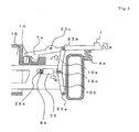
grasping member 103, is operated in this state (in the direction of arrow Z in the figure). This leads the protrusion of thelock lever 107 to come in contact with the plunger of the electromagnetic solenoid 115, and the rotation of thelock lever 107 is regulated. Hence, a state in which the lock pin 107a is pressed against theconcaved part 119 is maintained. Thus, the connector body 111 can be fixed with respect to thecase 109, and the connector body 111 will not come loose from the reception connector. - However, especially in cold climates, there are times when the electromagnetic solenoid 115 freezes and becomes inoperable. In such a case, the plunger does not move even when the electromagnetic solenoid 115 is worked, and the rotation of the
lock lever 107 cannot be regulated. For this reason, the operator is capable of releasing the lock lever while electric conduction takes place between the connector body 111 and the power reception connector during charging etc., to retract the connector body 111 with respect to thecase 109. When such operation takes place, as described previously, arc discharge may occur at the moment the connectors come apart. - Note that normally, a limit switch etc. detects the fitting of the lock pin 107a to the
concaved part 119, but there is a slight time-lag before the turn-off of the limit switch to the complete shutdown of electric conduction. Thus, when the operator operates thelock lever 107 to immediately pull out the connector during electric conduction, the occurrence of arc discharge cannot be prevented with certainty. - The present invention was made in view of such problems, and its object is to provide a power supply connector that can prevent the connector from disconnecting during electric conduction.
- In order to achieve the above-described object, the present invention provides a power supply connector for automobiles, which comprises: a connector body; a case for accommodating the connector body; a grasping member that is attached to the case; a lock lever that limits the movement of the case with respect to the grasping member; a link member that is connected to the lock lever and the grasping member; and an electromagnetic solenoid that is fixed to the grasping member; wherein a plunger of the electromagnetic solenoid is connected to the link member, the connector body and the grasping member are slidable in a direction of nearly the same axis line with respect to the case, when the lock lever is in a released state, and by sliding the grasping member with respect to the case and locking the lock lever to the case, the link member operates along with the operation of the lock lever, while the position of the plunger connected to the link member changes, and further, by operating the electromagnetic solenoid, a locked state, in which the lock lever is locked to the case by the link member, is maintained.
- The case preferably comprises a limit switch that is capable of detecting the locked state of the lock lever.
- It is preferable that the electromagnetic solenoid operates when a state of electric conductibility with respect to the connector body is obtained, by detecting the locked state of the lock lever with the limit switch, and electricity is conducted to the connector body.
- It is preferable that the power supply connector further comprises: a first spring that presses the lock lever towards a direction of obtaining a locked state for the lock lever; and a second spring that retracts the plunger to the direction of the electromagnetic solenoid; wherein the sum of the force of pressing the plunger against the link member with the electromagnetic solenoid and the force of pulling out the plunger by moving the link member through the operation of the lock lever with the first spring, is larger than the retracting force of the plunger by the second spring.
- According to the present invention, because the plunger of the electromagnetic solenoid moves via a link member when the lock lever is locked, when the plunger of the electromagnetic solenoid is inoperative due to freezing etc., the rotation of the lock lever becomes limited, and loses its function as a locking means that limits the movement of the case with respect to the grasping member. Thus, the fact that the plunger of the electromagnetic solenoid is unable to move due to freezing etc., can be perceived with certainty.
- Further, by operating the electromagnetic solenoid, the lock lever can be fixed at a locked state. Thus, disconnection of the connector during electric conduction can be prevented.
- Furthermore, by installing a detection means such as a limit switch etc., which detects the locked state of the lock lever, detachment of the connector during electric conduction can be prevented with more certainty.
- Further, because electric conduction is made possible only when a locked state is detected by the detection means, and because the electromagnetic solenoid always operates during electric conduction, incorrect operation of the lock lever can be prevented with certainty.
- Moreover, by providing a first spring that presses the lock lever towards the direction of obtaining a locked state of the lock lever, the lock lever automatically turns to a locked state when the connector body moves with respect to the case. Therefore, excellent operability is obtained. Further, by setting the sum of the force of pressing the plunger with the electromagnetic solenoid and the force of pulling out the plunger with the first spring to be larger than the restoring force of the plunger by the second spring, the lock lever can be fixed with certainty.
- According to the present invention, a power supply connector that can prevent the disconnection of the connector during electric conduction can be provided.
-
-
FIG 1 is a figure that shows thepower supply connector 1, and (a) is a side view, and (b) is a sectional side view. -
FIG 2 is an enlarged view of the vicinity of thelock lever 7 of thepower supply connector 1. -
FIG 3 is a figure that shows thepower supply connector 1 at a state of operation, and (a) is a side view, and (b) is a sectional side view. -
FIG 4 is an enlarged view of the vicinity of thelock lever 7 of thepower supply connector 1 at a state of operation. -
FIG 5 is a figure that shows a state in which thepower supply connector 1 is connected to thepower reception connector 33, and (a) is a sectional side view, and (b) is a bottom perspective view showing the movement of theslider 25 etc. -
FIG 6 is a figure that shows a state in which thepower supply connector 1 is connected to thepower reception connector 33, and (a) is a sectional side view, and (b) is a bottom perspective view showing the movement of theslider 25 etc. -
FIG 7 is a figure that shows a state in which thepower supply connector 1 is connected to thepower reception connector 33, and (a) is a sectional side view, and (b) is a bottom perspective view showing the movement of theslider 25 etc. -
FIG 8 is an enlarged view of the vicinity of thelock lever 7 at a state in which theelectromagnetic solenoid 22 is operated. -
FIG 9 is a front view of a state in whichmultiple sliders 25 are provided. -
FIG 10 is an enlarged view of the vicinity of thelock lever 7 of another embodiment. -
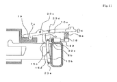
FIG 11 is an enlarged view of the vicinity of thelock lever 7 at a state in which thepower supply connecter 1 of another embodiment is operated. -
FIG 12 is an enlarged view of the vicinity of thelock lever 7 at a state in which theelectromagnetic solenoid 22 of another embodiment is operated. -
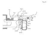
FIG 13 is an enlarged view of the vicinity of thelock lever 7 of yet another embodiment. -
FIG 14 is an enlarged view of the vicinity of thelock lever 7 at a state in which theelectromagnetic solenoid 22 of yet another embodiment is operated. -
FIG 15 is a figure showing a conventionalpower supply connector 100. - Hereinafter, embodiments of the present invention will be described with reference to the accompanying figures.
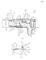
FIG 1 is a schematic diagram that indicates thepower supply connector 1, andFIG 1(a) is a side view, andFIG 1(b) is a sectional side view. Note that in the present invention, the state shown inFIG 1 is referred to as the normal state. Further, in the following figures, cables and such are abbreviated from the figure. Thepower supply connector 1 mainly comprises a graspingmember 3, acase 9 and aconnector body 11. - As shown in
FIG 1(a) and FIG 1(b) , the graspingmember 3 comprises ahandle 5 on one end (rear). Thehandle 5 is the part that is held by the operator when handling thepower supply connector 1. Here, thehandle 5 is formed so that at least part of thehandle 5 is positioned on a line that extends from the central axis of theconnector body 11. Thus, when the graspingmember 3 is pushed in, force can be applied to theconnector body 11 in a straight manner against the connection target. Therefore, the power supply connector shows excellent operability. - The interior of the grasping
member 3 can accommodate various structures. Acase 9 is provided on the other end (front) of the graspingmember 3. The vicinity of the front end of the graspingmember 3 is cylindrical, and part (rear end) of thecase 9 is accommodated within the graspingmember 3. The graspingmember 3 can slide back and forth with respect to thecase 9. - The
case 9 is a cylindrical member and theconnector body 11 is accommodated in the front end of thecase 9. Theconnector body 11 can slide back and forth with respect to thecase 9. Note that each slidable part of the graspingmember 3 and theconnector body 11, with respect to thecase 9, may contain guide mechanisms and stoppers that regulate the slidable area, which are abbreviated from the figure. - Inside the
case 9 is provided anarm 13. The vicinity of one end of thearm 13 is rotatably attached to thecase 9 with a pin 23a. The vicinity of the other end of thearm 13 is connected to aconnection bar 16, which is joined to the graspingmember 3, at a linkage 15a. At the linkage 15a, both parts are rotatably connected by an elongated hole formed on thearm 13 and a pin etc. formed on theconnection bar 16. - The
arm 13 is connected to theconnector body 11 by the linkage 15b substantially at the center (between pin 23a and linkage 15b). The structure of linkage 15b is similar to that of linkage 15a. That is, when thearm 13 rotates, theconnector body 11 and the graspingmember 3 are movable on a straight line with respect to thecase 9, along with the rotation of thearm 13. - In the
case 9 is provided a lockingmember 17. The lockingmember 17 is rotatably attached to thecase 9 by a pin 23b. A lock pin 17a is formed in an upward direction at the front end of the lockingmember 17. The lock pin 17a is arranged at the position of an opening formed on thecase 9. - At the rear end of the locking
member 17 is provided a joint 17b in a downward direction. The joint 17b is in a convex shape that can fit a joint 21. The joint 21 is fixed on the graspingmember 3. In a normal state, thejoints 17b and 21 do not fit and the protrusion of the joint 17b is positioned on top of the protrusion of the joint 21. Further, in this state, because the joint 17b is pushed up by the joint 21 in an upward direction, the lock pin 17a does not protrude from the case 9 (the opening formed on the case 9) and remains within thecase 9 via pin 23b. - Inside the
case 9 is provided aslider 25. One end of theslider 25 protrudes toward the front of thecase 9. That is, a level difference is formed in the front of thecase 9, and theslider 25 is exposed through this level difference. Theslider 25 is slidable in the axial direction (the movement direction of thecase 9, which is the insertion-extraction direction of the connector). - In part of the
case 9 is formed anopening 24. Theopening 24 allows observation of the position of theslider 25 within thecase 9. Note that the arrangements of theslider 25 and theopening 24 are not limited to that shown in the figure and may be set arbitrarily. For example, theopening 24 may be arranged on the top surface or the side surface of thecase 9 for easier observation, and theslider 25 may be arranged on the top or side of the power supply connector. - In the rear side of the
slider 25 in the vicinity of the tip of theconnection bar 16, is provided a lockingmember 27. The lockingmember 27 comes in contact with theslider 25 and is movable in response to the movement of theslider 25. The lockingmember 27 locks thecase 9 and the graspingmember 3. That is, the lockingmember 27 functions as a case-lock mechanism that locks thecase 9 from moving with respect to the graspingmember 3. Note that details of the mechanisms and movements of theslider 25, which is an insertion detection means, and the lockingmember 27, which is a case-lock mechanism, will be described later. - A
lock lever 7, which is the operation part, is provided within the graspingmember 3. Thelock lever 7 is rotatably attached to the graspingmember 3 by a pin 23c. The rear side end of thelock lever 7 protrudes out from the graspingmember 3, allowing the operator to operate thelock lever 7 from the outside. A lock pin 7a is provided at the front of thelock lever 7 in a downward direction. The lock pin 7a comes in contact with part of thecase 9, and is normally in a state of being pushed up. On thecase 9 at the front side of the part that comes in contact with the lock pin 7a in a normal state, aconcaved part 19, to which the lock pin 7a can fit into, is provided. - Further, a spring 8a is provided in the vicinity of the rear end of the
lock lever 7. The spring 8a pushes up the vicinity of the rear end of thelock lever 7. That is, the lock pin 7a is pressed downward with the pin 23c as the fulcrum point. - An
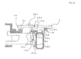
electromagnetic solenoid 22 is connected to thelock lever 7 via link members 10a, and 10b.FIG 2 is an enlarged view of the vicinity of thelock lever 7. At a position of thelock lever 7 further behind the pin 23c, one end of the link member 10a is rotatably connected with pin 23d. - The other end of the link member 10a is rotatably connected to one end of the link member 10b by a linkage 15c. Further, the other end of link member 10b is rotatably connected to the grasping
member 3 by a pin 23e. Note that in a normal state, link members 10a and 10b are arranged at an angle from each other so that they are bent forward at the linkage 15c. - The
electromagnetic solenoid 22 is fixed to the graspingmember 3 in the vicinity of the linkage 15c. A plunger 22a penetrates the interior of theelectromagnetic solenoid 22, and the plunger 22a can be operated by operating theelectromagnetic solenoid 22. The end of the plunger 22a is connected to the linkage 15c. The plunger 22a is connected toward the rear side from the bent part (front) of the link members 10a and 10b in a normal state. - A spring 8b is provided on the
electromagnetic solenoid 22. The spring 8b applies force to the plunger 22a in a direction that retracts the plunger 22a toward the rear. Thus, in a normal state, the plunger 22a is pulled toward the front side by the spring 8b, which also causes the linkage 15c to be pulled toward the front. The link members 10a and 10b receive force in a direction that decreases their angle by the linkage 15c being pulled toward the front. Here, because the pin 23e is fixed to the graspingmember 3, the pin 23d goes in a state of being pulled downward. - Next, a state in which the
power supply connector 1 is operated will be described.FIG 3 is a figure that shows thepower supply connector 1 in a state where the grasping member is moved, andFIG 3(a) is a side view, andFIG 3(b) is a sectional side view. - As described previously, in the normal state, the grasping
member 3 and thecase 9 are locked by the lockingmember 27. When theslider 25 is pushed in (in the direction of arrow A in the figure) from this state, the lockingmember 27 is pushed by theslider 25 and the lockingmember 27 moves. At this moment, the lock between the graspingmember 3 and thecase 9 is released by the movement of the lockingmember 27. - When the grasping
member 3 is moved forward with respect to the case 9 (in the direction of arrow C in the figure) in a state where the lock between thecase 9 and the graspingmember 3 is released, the linkage 15a, which is jointed to the grasping member 3 (connection bar 16), is pushed in toward the front. Because the linkage 15a moves forward, thearm 13 rotates (in the direction of arrow D in the figure) with the pin 23a as its axis of rotation. Theconnector body 11, which is connected to thearm 13 with the linkage 15b, moves toward the same direction as the grasping member 3 (in the direction of arrow E in the figure), due to the rotation of thearm 13. - Note that the distance of movement for the grasping
member 3 and the distance of movement for theconnector body 11 with respect to thecase 9 differ, because the coupling positions to thearm 13 differ for the graspingmember 3 and theconnector body 11. Specifically, when the ratio of the distance of the linkages 15a and 15b from the pin 23a is 2:1, then if the distance of movement of the graspingmember 3 with respect to thecase 9 is set as 2, the distance of movement of theconnector body 11 becomes 1. That is, the mechanism of thearm 13 etc., functions as a deceleration mechanism. By having a deceleration mechanism, the insertion-extraction process of the connector can be performed with little force. - Further, because the grasping
member 3 moves forward with respect to thecase 9, joint 17b and joint 21 join together to fit. Thus, the lockingmember 17 rotates with the pin 23b serving as its axis of rotation. That is, the lockingmember 17 rotates because the joint 17b side is pushed downward, and the lock pin 17a on the other end is pushed upward. Thus, the lock pin 17a protrudes outward (in the direction of arrow G in the figure) from thecase 9 through the opening. Note that the lockingmember 17 may be formed with a spring etc., so that it constantly tries to return to the state shown inFIG 3 (a state wherein the joint 17b is pushed down). - Further, because the grasping
member 3 moves forward with respect to thecase 9, the lock pin 7a of thelock lever 7 moves toward theconcaved part 19. At this moment, the vicinity of the rear end of thelock lever 7 is pushed upward by the spring 8a (in the direction of arrow F in the figure). Thus, thelock lever 7 rotates with the pin 23c serving as its axis of rotation. Hence, the lock pin 7a fits into theconcaved part 19. - A
limit switch 18, which is a detection means, is provided in the vicinity of theconcaved part 19 of thecase 9. When the lock pin 7a fits into theconcaved part 19, the tip of thelock lever 7 comes in contact with thelimit switch 18. Thus, the definite fitting of the lock pin 7a to theconcaved part 19 can be detected. Note that the detection means may be of other compositions. - When the
lock lever 7 operates, the force is conveyed to theelectromagnetic solenoid 22 via link members 10a and 10b.FIG 4 is an enlarged view of the vicinity of thelock lever 7. As described previously, the link member 10a is connected to thelock lever 7 by a pin 23d. Thus, by the upward movement of thelock lever 7, the link member 10a is pulled upward (in the direction of arrow J in the figure). - At this point, the bottom end of the link member 10b is fixed to the grasping
member 3 by the pin 23e. Thus, link members 10a and 10b move in the direction that increases their angle, along with the movement of thelock lever 7. That is, the linkage 15c moves backward. - At this moment, the plunger 22a connected to the linkage 15c moves toward the rear side (in the direction that protrudes from the
electromagnetic solenoid 22 body,) (in the direction of arrow K in the figure) in opposition to the restoration force of the spring 8b. Thus, when the plunger 22a is unable to move with respect to theelectromagnetic solenoid 22 body due to freezing etc., the linkage 15c cannot move. Hence, in such a case, thelever 7 cannot rotate around the pin 23c, and the state ofFIG 4 , wherein the lock pin 7a is fit into theconcaved part 19, cannot be obtained. Therefore, the operator can understand whether or not the plunger 22a is in a movable state. - If the plunger 22a is in a movable state, the lock pin 7a fits into the
concaved part 19 by thelock lever 7 operating. Thus, the movement of the graspingmember 3 with respect to thecase 9 is locked. That is, thelock lever 7 functions as a locking means that locks the grasping member 3 (and the connector body 11) from moving with respect to thecase 9, and functions as a release mechanism of the same lock by operating the lock lever 7 (pressing down the outside end of the lock lever 7). Thus, the connected state of the connector can be maintained with certainty, while further allowing easy release. - Note that a display part that shows the position of the
lock lever 7 may be provided at the top part of thehandle 5. For example, in the normal state shown inFIG 1 , thelock lever 7 is in a state in which the lock pin 7a side is pushed up. Thus, thelock lever 7 is in a state of being rotated toward the right side in the figure, with the pin 23c serving as the axis. On the other hand, in a state shown inFIG 3 , thelock lever 7 is in a state in which the lock pin 7a side is pushed down. Thus, thelock lever 7 is in a state of being rotated toward the left side in the figure with the pin 23c serving as the axis. - That is, by providing an opening on part of the grasping
member 3 to serve as a display part that enables confirmation of the state of thelock lever 7, whether thepower supply connector 1 is in a locked state (the state ofFIG 3 ) or in a released state (normal state) can easily be observed. Note that the method of observation of the state of thelock lever 7 and the arrangement of the display part can be any method. - Further, a parallel link may be used as the sliding part of the grasping member 3 (or the connector body 11) and the
case 9. By using a parallel link, rattling of the grasping member 3 (or the connector body 11) and thecase 9 during sliding is less likely to occur, and the moving range can be regulated. - Next, the method of utilizing the
power supply connector 1 will be described.FIG 5 to FIG 8 are figures that show the process of connecting thepower supply connector 1 to thepower reception connector 33, andFIG 5(a) to FIG 7(a) are sectional side views andFIG 5(b) to FIG 7(b) are bottom perspective views that show the movement of theslider 25 etc., andFIG 8 is a figure that shows the movement of theelectromagnetic solenoid 22. - First, as shown in
FIG 5(a) , thepower supply connector 1 in a normal state is faced toward thepower reception connector 33. Specifically, the tip of thecase 9 is inserted into the concaved part of the power reception connector. Note that aconnector body 37 is accommodated within thepower reception connector 33. In this state, the male-female terminals of theconnector bodies - Thus, as shown in
FIG 5(b) , the tip of theslider 25 does not come in contact with thepower reception connector 33 and protrudes from the front of thecase 9. Note that theslider 25 is constantly biased toward the front (in the direction of arrow H in the figure) by anelastic member 29 provided inside thecase 9. That is, theslider 25 always protrudes from the front of thecase 9 in the normal state. - A locking
member 27 is provided at the rear end of theslider 25 inside thecase 9. The lockingmember 27 is pushed toward the connection bar 16 (that is, perpendicular to the sliding direction of the slider 25) (in the direction of arrow I in the figure) by anelastic member 31. As shown in the figure, the side of the lockingmember 27 comes in contact with, for example, thepin 32 of theconnection bar 16. Thus, theconnection bar 16 is prevented from moving any further to the front by the lockingmember 27. For this reason, the graspingmember 3, to which theconnection bar 16 is fixed, is regulated from moving with respect to thecase 9 and becomes locked. - Thus, the grasping
member 3 would not move forward with respect to thecase 9, even when, for example, thecase 9 is inserted into thepower reception connector 33 obliquely, or thecase 9 comes in contact with the rim of thepower reception connector 33. That is, when the lockingmember 27, which is a case lock mechanism, is in the locked state, thecase 9 is not pushed in towards the interior of the graspingmember 3, even when the graspingmember 3 is pushed forward. - Note that part of the
slider 25 can be observed from theopening 24. Thus, in a state where theslider 25 protrudes forward, by putting a mark or a color on the part that corresponds to theopening 24, the state in which theslider 25 protrudes forward can be confirmed from theopening 24. - Further, in a state in which the case is arranged in the
power reception connector 33 side, aconcaved part 35 is formed at a position corresponding to the lock pin 17a, within thepower reception connector 33 side. To align the position of the lock pin 17a and theconcaved part 35, or to align the position of the aforementioned male-female terminals, a guide etc. may be formed on the outer surface of thecase 9 for determining the position in relation to the power reception connector. - Next, as shown in
FIG 6 , the grasping member of thepower supply connector 1 is pushed into thepower reception connector 33 side (in the direction of arrow C in the figure), which leads the level difference of thecase 9 to touch the rim of thepower reception connector 33. Since theslider 25 protrudes from the level difference part of thecase 9, theslider 25 comes in contact with the rim of thepower reception connector 33. - Thus, as shown in
FIG 6(b) , theslider 25 is pushed backward (inside the case 9) (in the direction of arrow A in the figure) in opposition to the force of theelastic member 29 that presses forward. The rear end of theslider 25 comes in contact with the lockingmember 27. A tapered part 27a is formed on the surface of the lockingmember 27 that comes in contact with theslider 25. - Thus, when the
slider 25 moves backward (in the direction of arrow A in the figure), the rear end of theslider 25 and the tapered part 27a slides, and converts the direction of movement of the lockingmember 27. That is, the lockingmember 27 moves in the direction perpendicular to the sliding direction of the slider 25 (in the direction of arrow B in the figure), in opposition to the pressing force of theelastic member 31. Thus, the lockingmember 27 moves in a direction away from thepin 32. This causes the locked state between the lockingmember 27 and the pin 32 (connection bar 16) to be released. - Note that the detection means for detecting whether or not the
case 9 has been inserted into thepower reception connector 33 is not limited to aslider 25 as shown in the figure, and may be any method as long as it operates when thecase 9 is inserted. Further, the mechanism for releasing the case lock mechanism when detected by the insertion detection means does not necessarily have to be a lockingmember 27 as shown in the figure, and may be any method depending on the insertion detection means, as long as it is able to release the locked state. - In this manner, when the
case 9 is completely inserted into thepower reception connector 33, the locked state of thecase 9 and the graspingmember 3 is released, and both become movable. Note that part of theslider 25 can be observed from theopening 24. Thus, by putting a mark or color at the position corresponding to the opening in a state wherein theslider 25 is pushed backward, the state of theslider 25 being pushed backward can be observed from theopening 24. That is, the secure insertion of thecase 9 to thepower reception connector 33 can be observed. - Next, as shown in
FIG 7 , thegrasping part 3 of thepower supply connector 1 is pushed into thepower reception connector 33 side (in the direction of arrow C in the figure). As previously stated, since thecase 9 comes in contact with thepower reception connector 33, it cannot be further pushed in. On the other hand, the locked state of the graspingmember 3 with respect to thecase 9 is released. That is, as shown inFIG 7(b) , thepin 32 does not come in contact with the lockingmember 27. Thus, theconnection bar 16 does not come in contact with the lockingmember 27 and moves forward (in the direction of arrow C in the figure). - For this reason, the grasping
member 3 can be moved forward with respect to thecase 9. At this point, theconnector body 11 moves forward with respect to the case 9 (in the direction of arrow E in the figure) along with the movement of the graspingmember 3. Thus, theconnector body 11 protrudes from the front of thecase 9 and connects to theconnector body 37 of the power reception connector side. - At this moment, when the ratio of the distance of movement of the grasping
member 3 and theconnector body 11 with respect to thecase 9 is 2:1, by pushing the grasping member in a movement distance that is twice the spare length of connection, which connects theconnector body 11 and theconnector body 37, theconnector body 11 can be moved just enough to allow the connectors to connect. That is, the connectors can be connected by pushing in the graspingmember 3 with half the force necessary for connecting the two connectors (interconnection resistance). Note that the deceleration ratio of the deceleration mechanism can be set arbitrarily, taking into consideration the interconnection resistance and operability. - Further, in the state shown in
FIG 7(a) , as described previously, the lock pin 17a fits into theconcaved part 35. For this reason, thepower reception connector 33 and thepower supply connector 1 are locked in a connected state. Further, the lock pin 7a at the end of thelock lever 7 fits into theconcaved part 19. Thus, even when the cable etc., which is abbreviated in the figure, is pulled, thepower supply connector 1 is not easily disconnected from thepower reception connector 33. - When the lock pin 7a fits into the
concaved part 19, thelimit switch 18 is turned ON by the tip of thelock lever 7. The connected connectors become electrically conductible by thelimit switch 18 being turned ON. - When electric conduction of the connectors begins, as shown in
FIG 8 , theelectromagnetic solenoid 22 operates. Theelectromagnetic solenoid 22 constantly pushes the plunger 22a toward the linkage 15c in opposition to the spring 8b (in the direction of arrow L in the figure) during electric conduction. The link members 10a and 10b move apart in an opening direction by the movement of the plunger 22a. Thus, the top part (pin 23d) of the link member 10a is pushed upward (in the direction of arrow M in the figure). Hence, it becomes impossible to release thelock lever 7 during electric conduction. For this reason, the operator cannot release the lock of thelock lever 7 during electric conduction, and the connection of the connector cannot be pulled out. - Note that when disconnecting the
power supply connector 1, by stopping electric conduction, the operation of theelectromagnetic solenoid 22 stops. When the electromagnetic solenoid stops, the plunger 22a is pulled backwards by the spring 8b. By pressing down the end of thelock lever 7 in this state, the lock pin 7a can be pushed up. By pulling back the graspingmember 3 after the lock pin 7a is released from theconcaved part 19, joint 17b moves above joint 21, which leads the lock by the lock pin 17a to be released. Thus, thepower supply connector 1 can easily be disconnected. - Note that although an example wherein one set of
slider 25 and lockingmember 27 was arranged was shown in the above-described example, the present invention is not limited to such. For example, as shown inFIG 9 , multiple pairs of sliders 25 (andcorresponding locking members 27 etc.) may be arranged. - When
multiple sliders 25 are used, it is preferable that they are arranged in a point symmetrical position with theconnector center 39, which is the center of the connector body 11 (case 9) from the front view of theconnector body 11, as its center point. By taking such position, the pushing force of theslider 25 works evenly against theconnector center 39 when thecase 9 is inserted to thepower reception connector 33, and thus, thecase 9 can be inserted into thepower reception connector 33 more precisely. - As described above, by using the
power supply connector 1 of the present embodiment, connection with the power reception connector can be easily performed without the use of large force. In particular, because the pushing movement of the grasping member by the operator matches the direction of connection of theconnector body 11 in thepower supply connector 1, the operator can easily understand the connection process instinctively. - Further, by gearing the plunger 22a of the
electromagnetic solenoid 22 with the movement of thelock lever 7, the plunger 22a can be moved slightly when locking thelock lever 7. Thus, when the plunger 22a is in an inoperable state due to freezing etc., thelock lever 7 loses its function as a locking means. Hence, electric conduction can only be made possible when theelectromagnetic solenoid 22 operates. - At this point, because the
electromagnetic solenoid 22 is constantly in operation during electric conduction, thelock lever 7 cannot be released during electric conduction. Thus, the operator is unable to release thelock lever 7 to pull out the connector during electric conduction. Hence, the occurrence of arc discharge etc. due to disconnection of the connector during electric conduction can be prevented. - Further, by providing a case lock mechanism that locks the
case 9 and the graspingmember 3, in a normal state, the graspingmember 3 cannot move with respect to thecase 9. Thus, the graspingmember 3 cannot be moved into thecase 9, while thecase 9 is not completely inserted into thepower reception connector 33. - Although embodiments of the present invention have been described in detail above with reference to the accompanying figures, the present invention is not limited to such embodiments. It should be obvious to those in the field that examples of various changes and modifications are included within the realm of the technical idea of the present invention, and it should be understood that such examples are included in the technical scope of the present invention.
- For example, the shape of the grasping
member 3, as well as the arrangements and shapes of various compositions within thecase 9, are not limited to those exemplified in the figures. Further, the structure of the deceleration mechanism is not limited to those exemplified in the figures. - Furthermore, the structure of the link members 10a and 10b are not limited to those described above. For example,
FIG 10 is an enlarged view of the vicinity of thelock lever 7 in another embodiment. In the example shown inFIG 10 , one end of the link member 10a is rotatably connected to the lock lever by a pin 23d, in a position that is toward the rear side of the pin 23c of thelock lever 7. The link member 10a is a member that is bent in a nearly-hooked shape. - The other end of the link member 10a is rotatably connected to the link member 10b by a linkage 15d. Further, one end of the link member 10b is rotatably connected to the grasping
member 3 by a pin 23e. - The other end of the link member 10b is coupled to the end of the plunger 22a of the
electromagnetic solenoid 22 at a linkage 15c. Note that in a normal state, the plunger 22a is pushed forward by the spring 8b. Thus, the link member 10b is in a state of being rotated forward (counter-clockwise in the figure) with the pin 23e serving as its fulcrum point. - When the power supply connector is operated from this state (the state of
FIG 3 ), as shown inFIG 11 , the lock pin 7a fits into theconcaved part 19. This causes the rear side of thelock lever 7 to rotate upward (in the direction of arrow N in the figure) with the pin 23d serving as its fulcrum point. Thus, the pin 23d also moves upward with the rotation of thelever 7. Hence, the link member 10a is lifted upward. - Since the bottom end of the link member 10a is connected to part of the link member 10b, the linkage 15d of the link members 10a and 10b are lifted upward. Thus, in a normal state, the link member 10b, which was in a slightly slanted state, rotates as if to stand upward (counter-clockwise in the figure) with the pin 23e serving as its fulcrum point. Thus, the linkage 15c moves backward, pushing back the plunger 22a (in the direction of arrow O in the figure). The
limit switch 18 is pushed in by the plunger 22a due to the plunger 22a being pushed back. This enables the detection of the lock pin 7a being fit into theconcaved part 19 with precision. - As described above, when the plunger 22a cannot move with respect to the
electromagnetic solenoid 22 body due to freezing etc., the linkage 15c cannot move. Thus, in such case, thelock lever 7 cannot rotate around the pin 23c, and the lock pin 7a cannot be in a state of fitting into theconcaved part 19. For this reason, the operator can determine whether or not the plunger 22a is in an operable state. - When electric conduction through the connector begins, the
electromagnetic solenoid 22 operates as shown inFIG 12 . The movement of the plunger 22a pulls the link member 10b toward the back (in the direction of arrow P in the figure). Thus, the top end part of the link member 10a (pin 23d) is pushed upward. Hence, it becomes impossible to perform a release operation of thelock lever 7 during electric conduct. Therefore, the operator cannot release thelock lever 7, and the connector cannot be pulled out during electric conduction. - As described above, even in the compositions shown in
FIG 10 to FIG 12 , the aforementioned effects can be obtained. That is, in the present invention, the shapes etc. of the link members 10a and 10b do not matter. The shapes and arrangements of link members 10a and 10b, and the operation direction of theelectromagnetic solenoid 22 etc, may be appropriately set, as long as the plunger 22a of theelectromagnetic solenoid 22 can be operated along with the operation of thelock lever 7. - Further, the composition shown in
FIGs 13 to 14 may also be taken. The composition ofFIG 13 is similar to that ofFIG 10 , but thelimit switch 18 comes in contact with thelock lever 7. That is, the limit switch is pushed in at a state in which thelock lever 7 is released. - In contrast, as shown in
FIG 14 , when the lock pin 7a fits into theconcaved part 19, thelock lever 7 rotates, and detaches from thelimit switch 18. The state of thelock lever 7 can also be detected by thelimit switch 18 in this manner. - The detection mechanism of the
limit switch 18, which is a detection means for detecting the locked state of thelock lever 7, is not limited to that exemplified, as long as it can detect the locked state. For example, it may be operated by other parts such as the link member 10b etc. -
- 1
- power supply connector
- 3
- grasping member
- 5
- handle
- 7
- lock lever
- 7a
- lock pin
- 8a, 8b
- spring
- 9
- case
- 10a, 10b
- link member
- 11
- connector body
- 13
- arm
- 15a, 15b, 15c, 15d
- linkage
- 16
- connection bar
- 17
- locking member
- 17a
- lock pin
- 17b
- joint
- 18
- limit switch
- 19
- concaved part
- 21
- joint
- 22
- electromagnetic solenoid
- 22a
- plunger
- 23a, 23b, 23c, 23d, 23e
- pin
- 24
- opening
- 25
- slider
- 27
- locking member
- 27a
- tapered part
- 29
- elastic member
- 31
- elastic member
- 32
- pin
- 33
- power reception connector
- 35
- concaved part
- 37
- connector body
- 39
- connector center
- 100
- power supply connector
- 103
- grasping member
- 105
- handle
- 107
- lock lever
- 107a
- lock pin
- 109
- case
- 111
- connector body
- 113
- pin
- 115
- electromagnetic solenoid
- 119
- concaved part
Claims (4)
- A power supply connector for automobiles, which comprises:a connector body;a case for accommodating the connector body;a grasping member that is attached to the case;a lock lever that limits the movement of the case with respect to the grasping member;a link member that is connected to the lock lever and the grasping member; andan electromagnetic solenoid that is fixed to the grasping member; whereina plunger of the electromagnetic solenoid is connected to the link member,the connector body and the grasping member are slidable in a direction of nearly the same axis line with respect to the case, when the lock lever is in a released state, andby sliding the grasping member with respect to the case and locking the lock lever to the case, the link member operates along with the operation of the lock lever, while the position of the plunger connected to the link member changes, and further,by operating the electromagnetic solenoid, a locked state, in which the lock lever is locked to the case by the link member, is maintained.
- The power supply connector according to Claim 1, wherein the case comprises a detection means that is capable of detecting the locked state of the lock lever.
- The power supply connector according to Claim 2, wherein a state of electric conductibility with respect to the connector body is obtained, by detecting the locked state of the lock lever with the detection means, and
electricity is conducted to the connector body, whereby the electromagnetic solenoid operates. - The power supply connector according to Claim 3, which further comprises:a first spring that presses the lock lever towards a direction of obtaining a locked state for the lock lever; anda second spring that retracts the plunger to the direction of the electromagnetic solenoid; whereinthe sum of the force of pressing the plunger against the link member with the electromagnetic solenoid and the force of pulling out the plunger by moving the link member through the operation of the lock lever with the first spring, is larger than the retracting force of the plunger by the second spring.
Applications Claiming Priority (2)
| Application Number | Priority Date | Filing Date | Title |
|---|---|---|---|
| JP2012078145A JP5916476B2 (en) | 2012-03-29 | 2012-03-29 | Power supply connector |
| PCT/JP2013/054129 WO2013145947A1 (en) | 2012-03-29 | 2013-02-20 | Power supply connector |
Publications (2)
| Publication Number | Publication Date |
|---|---|
| EP2833485A1 true EP2833485A1 (en) | 2015-02-04 |
| EP2833485A4 EP2833485A4 (en) | 2015-11-11 |
Family
ID=49259229
Family Applications (1)
| Application Number | Title | Priority Date | Filing Date |
|---|---|---|---|
| EP13769934.4A Withdrawn EP2833485A4 (en) | 2012-03-29 | 2013-02-20 | Power supply connector |
Country Status (5)
| Country | Link |
|---|---|
| US (1) | US9088101B2 (en) |
| EP (1) | EP2833485A4 (en) |
| JP (1) | JP5916476B2 (en) |
| CN (2) | CN103748746B (en) |
| WO (1) | WO2013145947A1 (en) |
Families Citing this family (25)
| Publication number | Priority date | Publication date | Assignee | Title |
|---|---|---|---|---|
| WO2013061400A1 (en) * | 2011-10-25 | 2013-05-02 | 住友電装株式会社 | Vehicle charging device |
| JP5798935B2 (en) * | 2012-01-17 | 2015-10-21 | 矢崎総業株式会社 | Electrical connector |
| JP5939927B2 (en) * | 2012-08-06 | 2016-06-22 | 矢崎総業株式会社 | Charging connector |
| WO2014033948A1 (en) * | 2012-09-03 | 2014-03-06 | 古河電気工業株式会社 | Power supply connector |
| CN104756328A (en) * | 2012-10-22 | 2015-07-01 | 古河电气工业株式会社 | Power supply connector |
| JP5718302B2 (en) * | 2012-11-19 | 2015-05-13 | 古河電気工業株式会社 | Power supply connector |
| WO2014157196A1 (en) * | 2013-03-28 | 2014-10-02 | 矢崎総業株式会社 | Charging connector |
| JP6148964B2 (en) * | 2013-10-17 | 2017-06-14 | 日本航空電子工業株式会社 | connector |
| JP5690914B1 (en) * | 2013-12-16 | 2015-03-25 | 株式会社フジクラ | Power supply connector |
| WO2016077690A1 (en) | 2014-11-14 | 2016-05-19 | Henderson Ricky Jay | Power docking port system |
| US9368911B2 (en) * | 2014-11-14 | 2016-06-14 | GM Global Technology Operations LLC | Systems and methods for self-closing electrical connector |
| CN104916972A (en) * | 2015-07-13 | 2015-09-16 | 沈素春 | Power supply device with moving roller |
| JP6452568B2 (en) * | 2015-07-24 | 2019-01-16 | 日本航空電子工業株式会社 | Electrical connector |
| JP6537938B2 (en) | 2015-09-02 | 2019-07-03 | 日本航空電子工業株式会社 | Connector and connector assembly |
| CN105576447B (en) * | 2016-02-26 | 2018-03-23 | 南京康尼新能源汽车零部件有限公司 | A kind of DC charging rifle provided with mechanical release mechanism |
| CN106229770B (en) * | 2016-08-30 | 2019-04-19 | 张家港友诚新能源科技股份有限公司 | A locking and unlocking device for a charging plug |
| CN108466565B (en) * | 2018-03-21 | 2019-01-29 | 深圳市鸿春新能源有限公司 | A kind of fast charge method of manifold type charging pile to new-energy automobile |
| JP2020146806A (en) * | 2019-03-14 | 2020-09-17 | 株式会社マキタ | Dust collection system |
| JP7321021B2 (en) * | 2019-07-26 | 2023-08-04 | シャープ株式会社 | Image forming apparatus and data protection method |
| CN111244694B (en) * | 2020-01-14 | 2021-04-20 | 南京多特蒙电气有限公司 | A flag-shaped terminal that will not loosen for long-term plugging and unplugging |
| CN112477656A (en) * | 2020-12-18 | 2021-03-12 | 蔚来汽车科技(安徽)有限公司 | DC charging gun and charging pile |
| CN114039248B (en) * | 2021-09-29 | 2024-07-16 | 华为数字能源技术有限公司 | Connector assembly and electronic device |
| US11990713B2 (en) * | 2021-10-25 | 2024-05-21 | Nvidia Corporation | Connector positioning system and method |
| CN114361877B (en) * | 2021-12-31 | 2023-09-08 | 核动力运行研究所 | Mechanical interlocking automatic connecting joint structure |
| JP7538185B2 (en) * | 2022-07-14 | 2024-08-21 | 矢崎総業株式会社 | Connector Locking Device |
Family Cites Families (17)
| Publication number | Priority date | Publication date | Assignee | Title |
|---|---|---|---|---|
| JP2978348B2 (en) * | 1992-12-18 | 1999-11-15 | 矢崎総業株式会社 | Power supply connector |
| US5433623A (en) * | 1993-04-19 | 1995-07-18 | Sumitomo Wiring Systems, Ltd. | Coupling device of charging connector assembly for electric car |
| JP2916348B2 (en) * | 1993-07-22 | 1999-07-05 | 住友電装株式会社 | Electric vehicle charging connector |
| JP3463820B2 (en) * | 1994-04-01 | 2003-11-05 | 矢崎総業株式会社 | Power supply connector |
| JP3292278B2 (en) * | 1995-12-06 | 2002-06-17 | 矢崎総業株式会社 | Electric vehicle charging connector |
| JP3262203B2 (en) * | 1996-02-16 | 2002-03-04 | 矢崎総業株式会社 | Low insertion / extraction force connector |
| JP3731797B2 (en) * | 1999-11-08 | 2006-01-05 | 矢崎総業株式会社 | Power supply connector |
| JP3866052B2 (en) * | 2001-05-24 | 2007-01-10 | 矢崎総業株式会社 | Power supply connector |
| JP4989097B2 (en) * | 2006-04-18 | 2012-08-01 | ダイコク電機株式会社 | Display device for gaming machine |
| WO2011081124A1 (en) * | 2009-12-28 | 2011-07-07 | 株式会社フジクラ | Power-feed connector |
| JP5393439B2 (en) * | 2009-12-28 | 2014-01-22 | 株式会社フジクラ | Power supply connector |
| JP5393440B2 (en) * | 2009-12-28 | 2014-01-22 | 株式会社フジクラ | Power supply connector |
| JP2011165609A (en) * | 2010-02-15 | 2011-08-25 | Tokai Rika Co Ltd | Lock structure of power supply plug |
| JP5482295B2 (en) * | 2010-03-01 | 2014-05-07 | 住友電装株式会社 | Charging connector |
| JP2011253671A (en) * | 2010-06-01 | 2011-12-15 | Tokai Rika Co Ltd | Power supply plug locking device |
| JP5603197B2 (en) * | 2010-10-06 | 2014-10-08 | 九州電力株式会社 | Power supply side connector |
| JP5697031B2 (en) * | 2011-02-24 | 2015-04-08 | 古河電気工業株式会社 | Power supply connector |
-
2012
- 2012-03-29 JP JP2012078145A patent/JP5916476B2/en not_active Expired - Fee Related
-
2013
- 2013-02-20 CN CN201380002764.8A patent/CN103748746B/en not_active Expired - Fee Related
- 2013-02-20 CN CN201610128512.5A patent/CN105680243A/en active Pending
- 2013-02-20 WO PCT/JP2013/054129 patent/WO2013145947A1/en not_active Ceased
- 2013-02-20 EP EP13769934.4A patent/EP2833485A4/en not_active Withdrawn
-
2014
- 2014-09-26 US US14/497,335 patent/US9088101B2/en not_active Expired - Fee Related
Also Published As
| Publication number | Publication date |
|---|---|
| JP2013206873A (en) | 2013-10-07 |
| CN103748746A (en) | 2014-04-23 |
| JP5916476B2 (en) | 2016-05-11 |
| CN103748746B (en) | 2016-03-30 |
| US20150011111A1 (en) | 2015-01-08 |
| US9088101B2 (en) | 2015-07-21 |
| CN105680243A (en) | 2016-06-15 |
| WO2013145947A1 (en) | 2013-10-03 |
| EP2833485A4 (en) | 2015-11-11 |
Similar Documents
| Publication | Publication Date | Title |
|---|---|---|
| US9088101B2 (en) | Power supply connector | |
| JP5503619B2 (en) | Power supply connector | |
| US9209563B2 (en) | Power supply connector and method for unlocking power supply connector | |
| EP2903100B1 (en) | Power supply connector | |
| EP2894726B1 (en) | Power supply connector | |
| JP5697031B2 (en) | Power supply connector | |
| US20140285148A1 (en) | Vehicle charging device | |
| CN103702859A (en) | Vehicle charging device | |
| JP5712418B2 (en) | Charging connector | |
| JP5298165B2 (en) | Charging connector | |
| JP2014150012A (en) | Connector | |
| JP5697053B2 (en) | Power supply connector | |
| JP5718302B2 (en) | Power supply connector | |
| JP2015072851A (en) | Connector |
Legal Events
| Date | Code | Title | Description |
|---|---|---|---|
| PUAI | Public reference made under article 153(3) epc to a published international application that has entered the european phase |
Free format text: ORIGINAL CODE: 0009012 |
|
| 17P | Request for examination filed |
Effective date: 20141016 |
|
| AK | Designated contracting states |
Kind code of ref document: A1 Designated state(s): AL AT BE BG CH CY CZ DE DK EE ES FI FR GB GR HR HU IE IS IT LI LT LU LV MC MK MT NL NO PL PT RO RS SE SI SK SM TR |
|
| AX | Request for extension of the european patent |
Extension state: BA ME |
|
| DAX | Request for extension of the european patent (deleted) | ||
| RA4 | Supplementary search report drawn up and despatched (corrected) |
Effective date: 20151008 |
|
| RIC1 | Information provided on ipc code assigned before grant |
Ipc: H01R 13/639 20060101AFI20151002BHEP Ipc: H01R 13/627 20060101ALI20151002BHEP Ipc: H01R 13/629 20060101ALI20151002BHEP Ipc: B60L 11/18 20060101ALI20151002BHEP |
|
| STAA | Information on the status of an ep patent application or granted ep patent |
Free format text: STATUS: EXAMINATION IS IN PROGRESS |
|
| 17Q | First examination report despatched |
Effective date: 20171018 |
|
| STAA | Information on the status of an ep patent application or granted ep patent |
Free format text: STATUS: THE APPLICATION HAS BEEN WITHDRAWN |
|
| 18W | Application withdrawn |
Effective date: 20171114 |