EP2833484A1 - Electric wire-to-substrate connector - Google Patents
Electric wire-to-substrate connector Download PDFInfo
- Publication number
- EP2833484A1 EP2833484A1 EP13769589.6A EP13769589A EP2833484A1 EP 2833484 A1 EP2833484 A1 EP 2833484A1 EP 13769589 A EP13769589 A EP 13769589A EP 2833484 A1 EP2833484 A1 EP 2833484A1
- Authority
- EP
- European Patent Office
- Prior art keywords
- connector
- plug
- wire
- lock
- receptacle
- Prior art date
- Legal status (The legal status is an assumption and is not a legal conclusion. Google has not performed a legal analysis and makes no representation as to the accuracy of the status listed.)
- Granted
Links
Images


Classifications
-
- H—ELECTRICITY
- H01—ELECTRIC ELEMENTS
- H01R—ELECTRICALLY-CONDUCTIVE CONNECTIONS; STRUCTURAL ASSOCIATIONS OF A PLURALITY OF MUTUALLY-INSULATED ELECTRICAL CONNECTING ELEMENTS; COUPLING DEVICES; CURRENT COLLECTORS
- H01R13/00—Details of coupling devices of the kinds covered by groups H01R12/70 or H01R24/00 - H01R33/00
- H01R13/62—Means for facilitating engagement or disengagement of coupling parts or for holding them in engagement
- H01R13/639—Additional means for holding or locking coupling parts together, after engagement, e.g. separate keylock, retainer strap
-
- H—ELECTRICITY
- H01—ELECTRIC ELEMENTS
- H01R—ELECTRICALLY-CONDUCTIVE CONNECTIONS; STRUCTURAL ASSOCIATIONS OF A PLURALITY OF MUTUALLY-INSULATED ELECTRICAL CONNECTING ELEMENTS; COUPLING DEVICES; CURRENT COLLECTORS
- H01R12/00—Structural associations of a plurality of mutually-insulated electrical connecting elements, specially adapted for printed circuits, e.g. printed circuit boards [PCB], flat or ribbon cables, or like generally planar structures, e.g. terminal strips, terminal blocks; Coupling devices specially adapted for printed circuits, flat or ribbon cables, or like generally planar structures; Terminals specially adapted for contact with, or insertion into, printed circuits, flat or ribbon cables, or like generally planar structures
- H01R12/70—Coupling devices
- H01R12/71—Coupling devices for rigid printing circuits or like structures
- H01R12/75—Coupling devices for rigid printing circuits or like structures connecting to cables except for flat or ribbon cables
-
- H—ELECTRICITY
- H01—ELECTRIC ELEMENTS
- H01R—ELECTRICALLY-CONDUCTIVE CONNECTIONS; STRUCTURAL ASSOCIATIONS OF A PLURALITY OF MUTUALLY-INSULATED ELECTRICAL CONNECTING ELEMENTS; COUPLING DEVICES; CURRENT COLLECTORS
- H01R13/00—Details of coupling devices of the kinds covered by groups H01R12/70 or H01R24/00 - H01R33/00
- H01R13/62—Means for facilitating engagement or disengagement of coupling parts or for holding them in engagement
- H01R13/627—Snap or like fastening
- H01R13/6271—Latching means integral with the housing
- H01R13/6273—Latching means integral with the housing comprising two latching arms
-
- H—ELECTRICITY
- H01—ELECTRIC ELEMENTS
- H01R—ELECTRICALLY-CONDUCTIVE CONNECTIONS; STRUCTURAL ASSOCIATIONS OF A PLURALITY OF MUTUALLY-INSULATED ELECTRICAL CONNECTING ELEMENTS; COUPLING DEVICES; CURRENT COLLECTORS
- H01R12/00—Structural associations of a plurality of mutually-insulated electrical connecting elements, specially adapted for printed circuits, e.g. printed circuit boards [PCB], flat or ribbon cables, or like generally planar structures, e.g. terminal strips, terminal blocks; Coupling devices specially adapted for printed circuits, flat or ribbon cables, or like generally planar structures; Terminals specially adapted for contact with, or insertion into, printed circuits, flat or ribbon cables, or like generally planar structures
- H01R12/70—Coupling devices
- H01R12/71—Coupling devices for rigid printing circuits or like structures
- H01R12/712—Coupling devices for rigid printing circuits or like structures co-operating with the surface of the printed circuit or with a coupling device exclusively provided on the surface of the printed circuit
- H01R12/716—Coupling device provided on the PCB
-
- H—ELECTRICITY
- H01—ELECTRIC ELEMENTS
- H01R—ELECTRICALLY-CONDUCTIVE CONNECTIONS; STRUCTURAL ASSOCIATIONS OF A PLURALITY OF MUTUALLY-INSULATED ELECTRICAL CONNECTING ELEMENTS; COUPLING DEVICES; CURRENT COLLECTORS
- H01R12/00—Structural associations of a plurality of mutually-insulated electrical connecting elements, specially adapted for printed circuits, e.g. printed circuit boards [PCB], flat or ribbon cables, or like generally planar structures, e.g. terminal strips, terminal blocks; Coupling devices specially adapted for printed circuits, flat or ribbon cables, or like generally planar structures; Terminals specially adapted for contact with, or insertion into, printed circuits, flat or ribbon cables, or like generally planar structures
- H01R12/70—Coupling devices
- H01R12/82—Coupling devices connected with low or zero insertion force
- H01R12/83—Coupling devices connected with low or zero insertion force connected with pivoting of printed circuits or like after insertion
-
- H—ELECTRICITY
- H01—ELECTRIC ELEMENTS
- H01R—ELECTRICALLY-CONDUCTIVE CONNECTIONS; STRUCTURAL ASSOCIATIONS OF A PLURALITY OF MUTUALLY-INSULATED ELECTRICAL CONNECTING ELEMENTS; COUPLING DEVICES; CURRENT COLLECTORS
- H01R13/00—Details of coupling devices of the kinds covered by groups H01R12/70 or H01R24/00 - H01R33/00
- H01R13/02—Contact members
- H01R13/10—Sockets for co-operation with pins or blades
- H01R13/11—Resilient sockets
-
- H—ELECTRICITY
- H01—ELECTRIC ELEMENTS
- H01R—ELECTRICALLY-CONDUCTIVE CONNECTIONS; STRUCTURAL ASSOCIATIONS OF A PLURALITY OF MUTUALLY-INSULATED ELECTRICAL CONNECTING ELEMENTS; COUPLING DEVICES; CURRENT COLLECTORS
- H01R12/00—Structural associations of a plurality of mutually-insulated electrical connecting elements, specially adapted for printed circuits, e.g. printed circuit boards [PCB], flat or ribbon cables, or like generally planar structures, e.g. terminal strips, terminal blocks; Coupling devices specially adapted for printed circuits, flat or ribbon cables, or like generally planar structures; Terminals specially adapted for contact with, or insertion into, printed circuits, flat or ribbon cables, or like generally planar structures
- H01R12/70—Coupling devices
- H01R12/77—Coupling devices for flexible printed circuits, flat or ribbon cables or like structures
- H01R12/81—Coupling devices for flexible printed circuits, flat or ribbon cables or like structures connecting to another cable except for flat or ribbon cable
Definitions
- the present invention relates to a wire-to-board connector.
- Patent Literature 1 discloses a connector including a socket connector 100 shown in Fig. 29 of this application, and a base connector 101 shown in Fig. 30 of this application.
- the socket connector 100 includes a housing 102 and a plurality of socket contacts (not shown) which are engaged with the housing 102. Lead wires extending substantially forward are respectively attached to the socket contacts.
- the base connector 101 is fixed to a printed circuit board by solder joining.
- the base connector 101 includes a housing 103 and a plurality of contacts 104 which are held by the housing 103.
- the housing 103 has a recess 105 which is opened in a direction away from the printed circuit board.
- the socket connector 100 is inserted into and removed from the recess 105 of the base connector 101 along an inserting/removing direction which is orthogonal to the printed circuit board.
- a pair of lock pieces 106 is formed so as to protrude from an end face of the housing 102 of the socket connector 100.
- a pair of mating grooves 107 is formed in the housing 103 of the base connector 101. In the state where the socket connector 100 and the base connector 101 are coupled together, the pair of lock pieces 106 of the housing 102 of the socket connector 100 are respectively mated with the pair of mating grooves 107.
- the pair of lock pieces 106 and the pair of mating grooves 107 constitute a lock mechanism for maintaining the state in which the socket connector 100 is engaged with base connector 101.
- Patent Literature 1 Japanese Patent No. 4020907
- Patent Literature 1 described above, there is a possibility that the socket connector 100 is disengaged from the base connector 101 when the lead wires are raised in the direction away from the printed circuit board. Meanwhile, there is a potential need for removing the socket connector 100 from the base connector 101 depending on the situation.
- a wire-to-board connector including: a plug connector including a plug contact to which a wire is attached, and a plug housing that holds the plug contact; and a receptacle connector that is mounted on a connector mounting surface of a board and includes a receptacle contact corresponding to the plug contact, and a receptacle housing that holds the receptacle contact, the plug connector being mated with the receptacle connector to thereby allow the plug contact to contact the receptacle contact.
- a vicinity portion of the wire In a mated state in which the plug connector is mated with the receptacle connector, a vicinity portion of the wire, the vicinity portion being located in the vicinity of the plug connector, extends along the connector mounting surface of the board.
- a mating direction in which the plug connector is mated with the receptacle connector is a direction approaching the connector mounting surface of the board.
- the plug housing includes a plug side surface as a side surface of the plug housing.
- the receptacle connector includes a side surface opposing portion that is opposed to the plug side surface in the mated state.
- the plug side surface is provided with a claw portion projecting toward the side surface opposing portion.
- the claw portion includes a plug lock surface that faces in a direction away from the connector mounting surface of the board and extends in a wire direction specified as a longitudinal direction of the vicinity portion in the mated state.
- the side surface opposing portion of the receptacle connector includes a receptacle lock surface that faces in a direction approaching the connector mounting surface of the board and is opposed to the plug lock surface in the mated state.
- the plug lock surface includes a lock maintaining surface disposed on a side in a connector wire direction in which the wire is viewed from the plug connector in the wire direction, and an unlocking surface disposed on a side in a wire connector direction which is opposite to the connector wire direction.
- the unlocking angle ⁇ 2 is greater than 90 degrees.
- the lock maintaining angle ⁇ 1 is equal to or smaller than 90 degrees.
- the unlocking surface is inclined so as to approach the plug side surface in the wire connector direction.
- the unlocking surface is connected to an edge of the lock maintaining surface on a side far from the plug side surface.
- an inclined surface that is inclined so as to approach the plug side surface in the wire connector direction is formed, and the inclined surface is connected to the unlocking surface.
- the side surface opposing portion includes a lock piece supporting portion and a lock piece that is supported by the lock piece supporting portion; the lock piece is formed in a cantilever shape including a lock piece held portion that is held by the lock piece supporting portion, and a lock piece opposing portion that is opposed to the plug side surface; the lock piece opposing portion is elastically displaceable in a direction away from the plug side surface; and the receptacle lock surface is formed in the lock piece opposing portion.
- the side surface opposing portion includes a displacement regulating portion that is disposed on a side opposite to the connector mounting surface of the board with the lock piece opposing portion interposed therebetween, thereby regulating the lock piece opposing portion from being elastically displaced in a direction away from the connector mounting surface of the board.
- the lock piece held portion and the lock piece opposing portion are formed so as to extend in the wire direction.
- an end in the wire connector direction of the lock piece held portion is coupled with an end in the wire connector direction of the lock piece opposing portion.
- the plug housing is provided with a releasing projection that allows the plug connector to be inclined in such a manner that the wire approaches the connector mounting surface of the board.
- the releasing projection is formed so as to protrude in the wire connector direction from an end in the wire connector direction of the plug housing.
- a wire-to-board connector including: a plug connector including a plug contact to which a wire is attached, and a plug housing that holds the plug contact; and a receptacle connector that is mounted on a connector mounting surface of a board and includes a receptacle contact corresponding to the plug contact, and a receptacle housing that holds the receptacle contact, the plug connector being mated with the receptacle connector to thereby allow the plug contact to contact the receptacle contact.
- a vicinity portion of the wire In a mated state in which the plug connector is mated with the receptacle connector, a vicinity portion of the wire, the vicinity portion being located in the vicinity of the plug connector, extends along the connector mounting surface of the board.
- a mating direction in which the plug connector is mated with the receptacle connector is a direction approaching the connector mounting surface of the board.
- the plug housing includes a plug side surface as a side surface of the plug housing.
- the receptacle connector includes a side surface opposing portion that is opposed to the plug side surface in the mated state.
- the plug side surface is provided with a claw portion projecting toward the side surface opposing portion.
- the claw portion includes a plug lock surface that faces in a direction away from the connector mounting surface of the board and extends in a wire direction specified as a longitudinal direction of the vicinity portion in the mated state.
- the side surface opposing portion of the receptacle connector includes a receptacle lock surface that faces in a direction approaching the connector mounting surface of the board and is opposed to the plug lock surface in the mated state.
- the plug lock surface includes a lock maintaining surface disposed on a side in a connector wire direction in which the wire is viewed from the plug connector in the wire direction, and an unlocking surface disposed on a side in a wire connector direction which is opposite to the connector wire direction.
- the unlocking surface is formed to be curved so as to approach the connector mounting surface of the board in a direction away from the plug side surface.
- a wire-to-board connector including: a plug connector including a plug contact to which a wire is attached, and a plug housing that holds the plug contact; and a receptacle connector that is mounted on a connector mounting surface of a board and includes a receptacle contact corresponding to the plug contact, and a receptacle housing that holds the receptacle contact, the plug connector being mated with the receptacle connector to thereby allow the plug contact to contact the receptacle contact.
- a vicinity portion of the wire In a mated state in which the plug connector is mated with the receptacle connector, a vicinity portion of the wire, the vicinity portion being located in the vicinity of the plug connector, extends along the connector mounting surface of the board.
- a mating direction in which the plug connector is mated with the receptacle connector is a direction approaching the connector mounting surface of the board.
- the plug housing includes a plug side surface as a side surface of the plug housing.
- the receptacle connector includes a side surface opposing portion that is opposed to the plug side surface in the mated state.
- the plug side surface is provided with a claw portion projecting toward the side surface opposing portion.
- the claw portion includes a plug lock surface that faces in a direction away from the connector mounting surface of the board and extends in a wire direction specified as a longitudinal direction of the vicinity portion in the mated state.
- the side surface opposing portion of the receptacle connector includes a receptacle lock surface that faces in a direction approaching the connector mounting surface of the board and is opposed to the plug lock surface in the mated state.
- the plug lock surface includes a lock maintaining surface disposed on a side in a connector wire direction in which the wire is viewed from the plug connector in the wire direction, and an unlocking surface disposed on a side in a wire connector direction which is opposite to the connector wire direction.
- the side surface opposing portion includes a lock piece supporting portion and a lock piece that is supported by the lock piece supporting portion.
- the lock piece is formed in a cantilever shape including a lock piece held portion that is held by the lock piece supporting portion, and a lock piece opposing portion that is opposed to the plug side surface.
- the lock piece opposing portion is elastically displaceable in a direction away from the plug side surface.
- the plug side surface of the plug housing is provided with an overhanging portion projecting toward the lock piece of the side surface opposing portion, and the overhanging portion is in contact with an elastically displaceable portion of the lock piece opposing portion in the mated state.
- the lock maintaining surface contacts the receptacle lock surface in advance of the unlocking surface.
- the plug connector is intentionally inclined in such a manner that the wire approaches the connector mounting surface of the board, the unlocking surface contacts the receptacle lock surface in advance of the lock maintaining surface.
- the mated state is easily maintained without releasing the opposed relationship between the plug lock surface and the receptacle lock surface, and when the plug connector is intentionally inclined in such a manner that the wire approaches the connector mounting surface of the board, the opposed relationship between the plug lock surface and the receptacle lock surface is released and thus the mated state is easily released. Consequently, a wire-to-board connector capable of maintaining the mated state even when the wire is raised in the direction away from the connector mounting surface of the board and capable of intentionally releasing the mated state is achieved.
- a wire-to-board connector 1 includes a plug connector 2 and a receptacle connector 3.
- the plug connector 2 includes a plurality of plug contacts 4 and a plug housing 5 that holds the plurality of plug contacts 4. Wires 6 are respectively attached to the plug contacts 4.
- the receptacle connector 3 includes a plurality of receptacle contacts 7, a receptacle housing 8 which holds the plurality of receptacle contacts 7, and a pair of assistant fittings 9 (lock pieces).
- the receptacle contacts 7 respectively correspond to the plug contacts 4.
- the receptacle connector 3 is mounted on a connector mounting surface 10a of a circuit board 10 (board).
- the plug connector 2 is mated with the receptacle connector 3, thereby allowing the plug contacts 4 to respectively contact the receptacle contacts 7.
- wire direction refers to a direction specified as a longitudinal direction of a vicinity portion 6a, which is a portion in the vicinity of the plug connector 2 of the wire 6, in a mated state in which the plug connector 2 is mated with the receptacle connector 3 as shown in Fig. 1 .
- the vicinity portion 6a of each wire 6 extends along the connector mounting surface 10a of the circuit board 10. Accordingly, it can be said that the wire direction is parallel to the connector mounting surface 10a of the circuit board 10.
- a direction in which the plurality of wires 6 are viewed from the plug connector 2 is defined as a connector wire direction and a direction in which the plug connector 2 is viewed from the plurality of wires 6 is defined as a wire connector direction.
- the term “connector height direction” refers to a direction orthogonal to the connector mounting surface 10a of the circuit board 10. The connector height direction is orthogonal to the wire direction.
- a direction approaching the connector mounting surface 10a of the circuit board 10 is defined as a board approaching direction and a direction separating from the connector mounting surface 10a of the circuit board 10 is defined as a board separating direction.
- the term “connector width direction” refers to a direction orthogonal to the wire direction and the connector height direction.
- the connector width direction is parallel to the connector mounting surface 10a of the circuit board 10.
- a direction approaching the center of the wire-to-board connector 1 is defined as a “connector width center direction” and a direction separating from the center of the wire-to-board connector 1 is defined as a “connector width anti-center direction”.
- wire direction the terms "wire direction”, “connector height direction”, and “connector width direction”, which are defined in the mated state in which the plug connector 2 is mated with the receptacle connector 3.
- a mating direction P in which the plug connector 2 is mated with the receptacle connector 3 is a direction approaching the connector mounting surface 10a of the circuit board 10.
- the mating direction P is orthogonal to the connector mounting surface 10a of the circuit board 10. Accordingly, the mating direction P coincides with the board approaching direction.
- the plurality of wires 6 are arranged side by side in the connector width direction.
- the plurality of receptacle contacts 7 are arranged side by side in the connector width direction.
- the receptacle connector 3 includes the plurality of receptacle contacts 7, the receptacle housing 8 which holds the plurality of receptacle contacts 7, and the pair of assistant fittings 9, as described above.
- the receptacle housing 8 includes a board opposing portion 15, a receptacle contact holding portion 16, and a pair of side portions 17 (lock piece supporting portions).
- the board opposing portion 15, the receptacle contact holding portion 16, and the pair of side portions 17, which constitute the receptacle housing 8, are integrally formed of a material having an insulating property, such as resin.
- the board opposing portion 15 is a flat plate parallel to the connector mounting surface 10a of the circuit board 10, and is formed in a rectangular shape elongated in the connector width direction.
- the receptacle contact holding portion 16 is a portion that is connected to an end in the wire connector direction of the board opposing portion 15, protrudes in the board separating direction, and extends in an elongated shape in the connector width direction.
- the receptacle contact holding portion 16 has a plurality of receptacle contact mounting holes 18 formed therein. Each receptacle contact mounting hole 18 is a hole for attaching each receptacle contact 7 to the receptacle housing 8.
- the plurality of receptacle contact mounting holes 18 are formed at a predetermined interval along the connector width direction.
- the plurality of receptacle contact mounting holes 18 are formed between both ends 19 in the connector width direction of the receptacle contact holding portion 16.
- Each receptacle contact mounting hole 18 is formed so as to penetrate the receptacle contact holding portion 16 in the wire direction. That is, each receptacle contact mounting hole 18 is formed so as to be opened in the wire connector direction and the connector wire direction.
- the both ends 19 are walls orthogonal to the wire direction.
- the pair of side portions 17 are respectively connected to the both ends in the connector width direction of the board opposing portion 15 and the receptacle contact holding portion 16, and are formed so as to protrude in the connector wire direction.
- the pair of side portions 17 is formed to be elongated along the wire direction.
- the pair of side portions 17 is formed in a symmetrical shape with respect to the center in the connector width direction of the wire-to-board connector 1. Accordingly, only one of the pair will be described, and the description of the other one of the pair will be omitted.
- the side portion 17 includes a positioning groove side partition wall portion 20, a positioning groove front partition wall portion 21, a press-fit groove side partition wall portion 22, a press-fit groove front partition wall portion 23, a press-fit groove inner partition wall portion 24, and a displacement regulating portion 25.
- the positioning groove side partition wall portion 20 is a wall that is connected to an end in the connector width anti-center direction at the corresponding end 19 of the receptacle contact holding portion 16, and extends in the connector wire direction.
- the positioning groove side partition wall portion 20 is orthogonal to the connector width direction.
- the positioning groove front partition wall portion 21 is a wall that is connected to an end in the connector wire direction of the positioning groove side partition wall portion 20, and extends in the connector width center direction.
- the positioning groove front partition wall portion 21 is orthogonal to the wire direction.
- the end 19 of the receptacle contact holding portion 16, and the positioning groove side partition wall portion 20 and the positioning groove front partition wall portion 21 of the side portion 17 constitute a positioning groove 41.
- the end 19 of the receptacle contact holding portion 16 defines a space in the wire connector direction of the positioning groove 41.
- the positioning groove side partition wall portion 20 defines a space in the connector width anti-center direction of the positioning groove 41.
- the positioning groove front partition wall portion 21 defines a space in the connector wire direction of the positioning groove 41.
- the press-fit groove side partition wall portion 22 is a wall that is connected to an end in the connector width anti-center direction of the positioning groove front partition wall portion 21, and extends in the connector wire direction.
- the press-fit groove side partition wall portion 22 is orthogonal to the connector width direction.
- the press-fit groove front partition wall portion 23 is a wall that is connected to an end in the connector wire direction of the press-fit groove side partition wall portion 22, and extends in the connector width center direction.
- the press-fit groove front partition wall portion 23 is orthogonal to the wire direction.
- the press-fit groove inner partition wall portion 24 is a wall that is connected to an end in the connector width center direction of the press-fit groove front partition wall portion 23, and extends in the wire connector direction.
- the press-fit groove inner partition wall portion 24 is orthogonal to the connector width direction.
- the press-fit groove side partition wall portion 22 and the press-fit groove inner partition wall portion 24 constitute a press-fit groove 26.
- the press-fit groove side partition wall portion 22 defines a space in the connector width anti-center direction of the press-fit groove 26.
- the press-fit groove inner partition wall portion 24 defines a space in the connector width center direction of the press-fit groove 26.
- the press-fit groove front partition wall portion 23 defines a space in the connector wire direction of the press-fit groove 26.
- the press-fit groove 26 is opened in the board separating direction.
- the press-fit groove 26 is formed to be elongated along the wire direction.
- An end 24a in the wire connector direction of the press-fit groove inner partition wall portion 24 is opposed to the positioning groove front partition wall portion 21.
- a gap “g" is formed between the end 24a of the press-fit groove inner partition wall portion 24 and the positioning groove front partition wall portion 21.
- the displacement regulating portion 25 is connected to an end in the connector wire direction of the press-fit groove inner partition wall portion 24, and is formed so as to protrude in the connector width center direction. As shown in Figs. 8 to 10 , the displacement regulating portion 25 is connected to a side in the board separating direction of the end in the connector wire direction of the press-fit groove inner partition wall portion 24.
- the displacement regulating portion 25 includes an inclined guide surface 27, an erect guide surface 28, and a regulating surface 29.
- the inclined guide surface 27 is a flat surface that is inclined in the board approaching direction toward the connector width center direction on a side in the board separating direction of an end in the connector width center direction of the displacement regulating portion 25.
- the erect guide surface 28 is a surface that is connected to an edge in the board approaching direction of the inclined guide surface 27 and is orthogonal to the connector width direction.
- the regulating surface 29 is a surface that is connected to an edge in the board approaching direction of the erect guide surface 28 and is orthogonal to the connector height direction.
- the pair of assistant fittings 9 is formed in a symmetrical shape with respect to the center in the connector width direction of the wire-to-board connector 1. Accordingly, only one of the pair will be described, and the description of the other one of the pair will be omitted.
- the assistant fitting 9 includes a lock piece held portion 30, a lock piece opposing portion 31, and a lock piece coupling portion 32.
- the assistant fitting 9 is formed by sheet metal bending.
- the lock piece held portion 30 is a portion held by the receptacle housing 8.
- the lock piece held portion 30 is formed so as to extend in the wire direction.
- the lock piece held portion 30 is orthogonal to the connector width direction.
- the lock piece held portion 30 includes a press-fitted portion 30a and a soldered leg portion 33.
- the press-fitted portion 30a is formed in a rod shape protruding in the board approaching direction.
- the soldered leg portion 33 is a portion that is soldered to the connector mounting surface 10a of the circuit board 10.
- the lock piece opposing portion 31 is formed so as to extend in the wire direction.
- the lock piece opposing portion 31 is orthogonal to the connector width direction.
- the lock piece opposing portion 31 includes an opposing portion body 34 and a regulated projection 35.
- the opposing portion body 34 is formed to be elongated in the wire direction.
- the opposing portion body 34 is orthogonal to the connector width direction.
- the opposing portion body 34 has a lock hole 36 which is formed in a substantially rectangular shape when viewed along the connector width anti-center direction.
- the lock hole 36 is formed to be elongated in the wire direction. Since the lock hole 36 is formed, a lock beam 37 which defines a space in the board separating direction of the lock hole 36 is formed on a side in the board separating direction of the lock hole 36.
- the lock beam 37 includes a receptacle lock surface 38, a plug opposing surface 39, and an assembly guide surface 40.
- the receptacle lock surface 38 is a surface that faces in the direction approaching the connector mounting surface 10a of the circuit board 10.
- the receptacle lock surface 38 is a flat surface that faces in the board approaching direction.
- the receptacle lock surface 38 is orthogonal to the connector height direction.
- the receptacle lock surface 38 is formed to be elongated in the wire direction.
- the plug opposing surface 39 is a flat surface that is connected to an edge in the connector width center direction of the receptacle lock surface 38 and faces in the connector width center direction.
- the plug opposing surface 39 is orthogonal to the connector width direction.
- the assembly guide surface 40 is a flat surface that is connected to an edge in the board separating direction of the plug opposing surface 39 and is inclined in the connector width center direction toward the board approaching direction.
- the regulated projection 35 is a portion that is connected to a side in the board approaching direction of an end in the connector wire direction of the opposing portion body 34 and is formed so as to protrude in the connector wire direction.
- the regulated projection 35 includes a regulated surface 35a that faces in the board separating direction.
- the regulated surface 35a is orthogonal to the connector height direction.
- the lock piece coupling portion 32 is a portion that couples an end in the wire connector direction of the lock piece held portion 30 with an end in the wire connector direction of the lock piece opposing portion 31.
- the lock piece coupling portion 32 is connected to an end in the wire connector direction of the lock piece held portion 30, and is formed so as to extend in the connector width center direction.
- the lock piece coupling portion 32 is orthogonal to the wire direction. An end in the connector width center direction of the lock piece coupling portion 32 is connected to an end in the wire connector direction of the lock piece opposing portion 31.
- the assistant fitting 9 includes the lock piece held portion 30, the lock piece opposing portion 31, and the lock piece coupling portion 32, thereby forming a U-shape when viewed along the board approaching direction.
- the plurality of receptacle contacts 7 are respectively press-fitted into the receptacle contact mounting holes 17 of the receptacle contact holding portion 16 of the receptacle housing 8.
- a direction in which the receptacle contacts 7 are respectively press-fitted into the receptacle contact mounting holes 18 corresponds to the connector wire direction.
- Each receptacle contact 7 is partially exposed in the connector wire direction as shown in Fig. 3 and is partially exposed in the board approaching direction as shown in Fig. 4 in the state where each receptacle contact 7 is attached to the receptacle housing 8.
- the pair of assistant fittings 9 are respectively attached to the pair of side portions 17 of the receptacle housing 8.
- the assistant fittings 9 are first positioned relative to the respective side portions 17 in such a manner that the lock piece held portion 30 of each assistant fitting 9 shown in Fig. 14 is inserted into the press-fit groove 26 of the corresponding side portion 17 of the receptacle housing 8 and the lock piece coupling portion 32 of each assistant fitting 9 is inserted into the gap "g" of the corresponding side portion 17 of the receptacle housing 8.
- the assistant fittings 9 are positioned relative to the respective side portions 17, the assistant fittings 9 are pushed in the board approaching direction.
- the lock piece held portion 30 of each assistant fitting 9 is inserted into the press-fit groove 26 of the corresponding side portion 17 of the receptacle housing 8.
- the press-fitted portion 30a also see Figs. 11 and 12
- the lock piece coupling portion 32 of each assistant fitting 9 is inserted into the gap "g" of the corresponding side portion 17 of the receptacle housing 8.
- the regulated projection 35 of the lock piece opposing portion 31 of each assistant fitting 9 passes over the inclined guide surface 27 of the displacement regulating portion 25 of the corresponding side portion 17 of the receptacle housing 8 in the connector width center direction, while the opposing portion body 34 of the lock piece opposing portion 31 is elastically displaced in the connector width center direction. Then, the regulated projection 35 slides on the erect guide surface 28 of the displacement regulating portion 25 in the board approaching direction.
- Fig. 15 shows a state in which each assistant fitting 9 is attached to the corresponding side portion 17 of the receptacle housing 8. As shown in Fig. 15 , each assistant fitting 9 is supported in a cantilever manner by the corresponding side portion 17 of the receptacle housing 8.
- the displacement regulating portion 25 and the regulated projection 35 face each other in the connector height direction. Specifically, the regulating surface 29 of the displacement regulating portion 25 shown in Fig. 10 and the regulated surface 35a of the regulated projection 35 shown in Fig. 11 are opposed to each other in the connector height direction. The opposed relationship between the displacement regulating portion 25 and the regulated projection 35 regulates the elastic displacement of the lock piece opposing portion 31 of each assistant fitting 9 shown in Fig. 15 in the board separating direction.
- a gap "h" is formed between the press-fit groove inner partition wall portion 24 of each side portion 17 and the lock piece opposing portion 31 of each assistant fitting 9 in the state where each assistant fitting 9 is attached to the corresponding side portion 17 of the receptacle housing 8. Accordingly, the lock beam 37 of the lock piece opposing portion 31 of each assistant fitting 9 is elastically displaceable in the connector width anti-center direction.
- a side surface opposing portion R corresponds to each side portion 17 and each assistance fitting 9 of the receptacle housing 8 as shown in Fig. 15 .
- the plug connector 2 shown in Figs. 17 and 18 includes the plurality of plug contacts 4 and the plug housing 5 that holds the plurality of plug contacts 4, as described above.
- the plug housing 5 includes a plug housing body 50, a releasing projection 51, a pair of positioning projections 52, and a pair of claw portions 53.
- the plug housing body 50 is a flat body with a small thickness in the connector height direction.
- the plug housing body 50 has a rectangular shape when viewed along the board approaching direction, and is formed to be elongated in the connector width direction.
- the plug housing body 50 has a plurality of plug contact mounting holes 54 formed therein.
- the plurality of plug contact mounting holes 54 are formed at a predetermined interval along the connector width direction.
- Each plug contact mounting hole 54 is formed so as to penetrate the plug housing body 50 in the wire direction. That is, each plug contact mounting hole 54 is formed so as to be opened in the wire connector direction and the connector wire direction.
- the plug housing body 50 includes a pair of plug side surfaces 50a serving as a pair of side surfaces of the plug housing body 50.
- Each of the pair of plug side surfaces 50a is a flat surface substantially parallel to both of the wire direction and the connector height direction. That is, each plug side surface 50a is substantially orthogonal to the connector width direction.
- the pair of plug side surfaces 50a is parallel to both of the wire direction and the connector height direction.
- the pair of plug side surfaces 50a is orthogonal to the connector width direction.
- Fig. 19 shows the plug contact 4 which is attached to an end of the wire 6.
- the plug contact 4 includes a pair of contact pieces 4a which contact the corresponding receptacle contact 7 so as to sandwich the receptacle contact 7.
- the plurality of plug contacts 4 are arranged side by side in the connector width direction.
- the plurality of plug contacts 4 are sandwiched by the pair of plug side surfaces 50a in the connector width direction. In other words, the pair of plug side surfaces 50a sandwich the plurality of plug contacts 4 in the connector width direction.
- the releasing projection 51 is connected to a side in the board separating direction of an end in the wire connector direction of the plug housing body 50, and is formed so as to protrude in the wire connector direction.
- the releasing projection 51 is formed to be elongated in the connector width direction.
- the pair of positioning projections 52 is formed in a symmetrical shape with respect to the center in the connector width direction of the wire-to-board connector 1. Accordingly, only one of the pair will be described, and the description of the other one of the pair will be omitted.
- the positioning projection 52 is connected to an end in the connector width direction of the end in the wire connector direction of the plug housing body 50, and is formed so as to protrude in the connector width anti-center direction.
- the pair of claw portions 53 is formed in a symmetrical shape with respect to the center in the connector width direction of the wire-to-board connector 1. Accordingly, only one of the pair will be described, and the description of the other one of the pair will be omitted.
- the claw portion 53 is connected to a side in the connector wire direction of the plug side surface 50a, and is formed so as to protrude in the connector width anti-center direction from the plug side surface 50a.
- the claw portion 53 is formed to be elongated in the wire direction. As shown in Fig. 20 , the claw portion 53 has a prism shape with a trapezoidal longitudinal sectional shape, and the side in the wire connector direction of the claw portion 53 is partially cut off.
- the claw portion 53 includes a plug lock surface 60, a mating guide surface 61, a side standing surface 62, an end standing surface 63, and an end inclined surface 64 (inclined surface).
- the plug lock surface 60 is a surface that faces in a direction away from the connector mounting surface 10a of the circuit board 10 and is elongated in the wire direction.
- the plug lock surface 60 includes a lock maintaining surface 65 that is disposed on the side in the connector wire direction, and an unlocking surface 66 that is disposed on the side in the wire connector direction.
- the lock maintaining surface 65 is a flat surface that is connected to the plug side surface 50a and is substantially orthogonal to the connector height direction.
- the unlocking surface 66 is a flat surface that is connected to the plug side surface 50a, is inclined in the connector width center direction toward the board separating direction, and is inclined in the connector width center direction toward the wire connector direction.
- the lock maintaining surface 65 and the unlocking surface 66 are connected to each other.
- the lock maintaining surface 65 and the unlocking surface 66 are adjacent to each other in the wire direction.
- the lock maintaining surface 65 is disposed on the side in the connector wire direction when viewed from the unlocking surface 66. That is, the unlocking surface 66 is disposed on the side in the wire connector direction when viewed from the lock maintaining surface 65.
- the unlocking surface 66 is connected to an edge 65a on a side far from the plug side surface 50a of the lock maintaining surface 65. In other words, the unlocking surface 66 is connected to the edge 65a on a side in the connector width anti-center direction of the lock maintaining surface 65.
- the mating guide surface 61 is a flat surface that faces in the direction approaching the connector mounting surface 10a of the circuit board 10 and is elongated in the wire direction.
- the mating guide surface 61 is inclined in the connector width center direction toward the board approaching direction.
- the side standing surface 62 is a flat surface that faces in the connector width anti-center direction and is elongated in the wire direction.
- the side standing surface 62 is orthogonal to the connector width direction.
- the side standing surface 62 is connected to the plug lock surface 60 and the mating guide surface 61.
- the side standing surface 62 is formed between the plug lock surface 60 and the mating guide surface 61.
- the end standing surface 63 is a flat surface that is connected to the plug side surface 50a and faces in the connector wire direction.
- the end standing surface 63 is orthogonal to the wire direction.
- the end standing surface 63 is connected to each of the plug lock surface 60, the mating guide surface 61, and the side standing surface 62.
- the end inclined surface 64 is a flat surface that is connected to the plug side surface 50a and faces in the wire connector direction and the connector width anti-center direction.
- the end inclined surface 64 is inclined in the connector width center direction toward the wire connector direction.
- the end inclined surface 64 is connected each of the unlocking surface 66 of the plug lock surface 60, the mating guide surface 61, and the side standing surface 62.
- the plug side surface 50a has a reference plane Q as indicated by an alternate long and two short dashes line in Fig. 20 .
- the reference plane Q is a part of the plug side surface 50a.
- the reference plane Q is a portion of the plug side surface 50a which is located on a side farther from the connector mounting surface 10a of the circuit board 10 than the claw portion 53.
- the reference plane Q is a portion of the plug side surface 50a which is located on the side in the board separating direction relative to the claw portion 53.
- Fig. 21 shows three cross-sections, i.e., a cross-section X, a cross-section Y, and a cross-section Z, of the claw portion 53.
- the cross-section X is located on the side in the connector wire direction relative to the cross-section Y.
- the cross-section Y is located on the side in the connector wire direction relative to the cross-section Z.
- the cross-section X, the cross-section Y, and the cross-section Z are cross-sections orthogonal to the wire direction.
- the shape of the claw portion 53 will be described in more detail by using the cross-section X, the cross-section Y, and the cross-section Z.
- an angle formed between the reference plane Q and the lock maintaining surface 65 is defined as a lock maintaining angle ⁇ 1.
- an angle formed between the reference plane Q and the unlocking surface 66 is defined as an unlocking angle ⁇ 2.
- the lock maintaining angle ⁇ 1 is smaller than the unlocking angle ⁇ 2.
- the lock maintaining angle ⁇ 1 is equal to or smaller than 90 degrees.
- the lock maintaining angle ⁇ 1 ranges from 70 to 90 degrees. More preferably, the lock maintaining angle ⁇ 1 ranges from 80 to 85 degrees. In this embodiment, the lock maintaining angle ⁇ 1 is 85 degrees, and the unlocking angle ⁇ 2 is greater than 90 degrees.
- the unlocking angle ⁇ 2 ranges from 95 to 165 degrees. More preferably, the unlocking angle ⁇ 2 ranges from 120 to 150 degrees. In this embodiment, the unlocking angle ⁇ 2 is 135 degrees.
- each plug contact 4 is attached to an end of the corresponding wire 6 as shown in Fig. 19 , and each plug contact 4 is inserted into the corresponding plug contact mounting hole 54 of the plug housing body 50 of the plug housing 5 in the wire connector direction as shown in Fig. 17 .
- each plug contact 4 is inhibited from being disengaged from the corresponding plug contact mounting hole 54.
- the receptacle connector 3 is preliminarily mounted on the connector mounting surface 10a of the circuit board 10 as shown in Fig. 2 .
- the soldered leg portion 33 also see Fig. 4
- the lock piece held portion 30 of each assistant fitting 9 shown in Fig. 11 is soldered to the connector mounting surface 10a (also see Fig. 2 ) of the circuit board 10.
- a soldered leg portion 7a of each receptacle contact 7 shown in Fig. 4 is soldered to the connector mounting surface 10a (also see Fig. 2 ) of the circuit board 10.
- the plug connector 2 is caused to descend in the mating direction P toward the receptacle connector 3. Then, the plug connector 2 and the receptacle 3 behave in the following manner.
- the plurality of wires 6 may be raised in the direction away from the connector mounting surface 10a of the circuit board 10 due to some operation.
- the plug housing 5 is inclined while being rotated clockwise.
- the lock maintaining surface 65 contacts the receptacle lock surface 38 in advance of the unlocking surface 66.
- the lock maintaining angle ⁇ 1 of the lock maintaining surface 65 is set to be equal to or smaller than 90 degrees. Accordingly, when the wires 6 are raised in the direction away from the connector mounting surface 10a of the circuit board 10, the mated state is maintained without releasing the opposed relationship between the plug lock surface 60 and the receptacle lock surface 38.
- the unlocking surface 66 contacts the receptacle lock surface 38 in advance of the lock maintaining surface 65.
- the unlocking angle ⁇ 2 of the unlocking surface 66 is set to be greater than 90 degrees. Accordingly, when the plug connector 2 is intentionally inclined so that the wires 6 approach the connector mounting surface 10a of the circuit board 10, the claw portion 53 pushes out the lock piece opposing portion 31 of the assistant fitting 9.
- the lock piece opposing portion 31 is regulated from being elastically displaced in the direction away from the connector mounting surface 10a of the circuit board 10.
- the gap "h" is secured between the lock piece opposing portion 31 and the press-fit groove inner partition wall portion 24. Accordingly, when the claw portion 53 pushes out the lock piece opposing portion 31 of the assistant fitting 9, the lock piece opposing portion 31 is elastically displaced only in the connector width anti-center direction, without being elastically displaced in the board separating direction. The elastic displacement of the lock piece opposing portion 31 in the connector width anti-center direction releases the opposed relationship between the plug lock surface 60 and the receptacle lock surface 38, thereby releasing the mated state of the wire-to-board connector 1.
- the lock maintaining surface 65 contacts the receptacle lock surface 38 in advance of the unlocking surface 66.
- the plug connector 2 is intentionally inclined so that the wires 6 approach the connector mounting surface 10a of the circuit board 10
- the unlocking surface 66 contacts the receptacle lock surface 38 in advance of the lock maintaining surface 65.
- the mated state is easily maintained without releasing the opposed relationship between the plug lock surface 60 and the receptacle lock surface 38, and when the plug connector 2 is intentionally inclined so that the wires 6 approach the connector mounting surface 10a of the circuit board 10, the opposed relationship between the plug lock surface 60 and the receptacle lock surface 38 is released, thereby facilitating the release of the mated state. Consequently, the wire-to-board connector 1 capable of maintaining the mated state even when the wires 6 are raised in the direction away from the connector mounting surface 10a of the circuit board 10 and capable of intentionally releasing the mated state is achieved.
- the receptacle lock surface 38 is formed in the assistant fitting 9 of the side surface opposed portion R in this embodiment, but instead may be formed in the side portion 17 of the side surface opposed portion R. In a modified example shown in Fig. 27 , the side surface opposing portion R does not include the assistant fitting 9. The side surface opposing portion R is formed of the side portion 17. The receptacle lock surface 38 is formed in the side portion 17.
- the unlocking surface 66 of the plug lock surface 60 is formed as a flat surface, but instead may be formed as a curved surface that is curved so as to approach the connector mounting surface 10a of the circuit board 10 in a direction away from the plug side surface 50a as shown in Fig. 28.
- Fig. 28 shows a cross-sectional shape of the curved unlocking surface 66 as indicated by a hatched area.
- the wire-to-board connector 1 capable of maintaining the mated state even when the wires 6 are raised in the direction away from the connector mounting surface 10a of the circuit board 10 and capable of intentionally releasing the mated state is achieved.
- the assistant fittings 9 Upon assembly of the receptacle connector 3, the assistant fittings 9 are positioned relative to the respective side portions 17, and the assistant fittings 9 are pushed in the board approaching direction. However, instead, the assistant fittings 9 may be pushed in the board separating direction. That is, upon attachment of the assistant fittings 9 to the respective side portions 17, the attachment direction is not limited to the board approaching direction.
- Fig. 31 shows the mated state of the wire-to-board connector 1.
- Fig. 32 is an enlarged view of a portion "G" shown in Fig. 31 .
- the lock piece opposing portion 31 of the assistant fitting 9 of the receptacle connector 3 is supported in a cantilever manner. Accordingly, an end 31 a which corresponds to the bottom of the lock piece opposing portion 31 and is located on the side of the lock piece coupling portion 32 of the lock piece opposing portion 31 is less likely to be elastically displaced in the connector width anti-center direction.
- the plug housing body 50 of the plug housing 5 of the plug connector 2 happens to contact the end 31a located on the side of the lock piece coupling portion 32 of the lock piece opposed portion 31 of the assistant fitting 9 of the receptacle connector 3 when the plug connector 2 is mated with the receptacle connector 3, the mating of the plug connector 2 with the receptacle connector 3 is considerably inhibited because the end 31a is less likely to be elastically displaced in the connector width anti-center direction as described above.
- a gap "i" is left between the plug side surface 50a of the plug housing body 50 of the plug housing 5 of the plug connector 2 and the lock piece opposing portion 31 of the assistant fitting 9 of the receptacle connector 3 in the mated state of the wire-to-board connector 1.
- each plug side surface 50a of the plug housing body 50 of the plug housing 5 of the plug connector 2 is provided with an overhanging portion 80 which projects toward the assistant fitting 9 (lock piece) of the side surface opposing portion R. That is, the overhanging portion 80 is formed so as to protrude in the connector width anti-center direction from the corresponding plug side surface 50a of the plug housing body 50.
- the overhanging portion 80 is in contact with an elastically displaceable portion of the lock piece opposing portion 31.
- the movement of the plug housing 5 of the plug connector 2 in the connector width direction within the receptacle connector 3 is suppressed by an elastic force N of the lock piece opposing portion 31 of the assistant fitting 9 of the receptacle connector 3 in the connector width center direction.
- the opposed relationship in the connector height direction between the receptacle lock surface 38 of the lock piece opposing portion 31 of the assistant fitting 9 shown in Fig. 15 and the lock maintaining surface 65 of the plug lock surface 60 of the claw portion 53 shown in Fig. 20 is maintained, thereby preventing the plug connector 2 from being easily disengaged from the receptacle connector 3.
- the plug housing 5 of the plug connector 2 includes a pair of overhanging portions 80 in addition to the plug housing body 50, the releasing projection 51, the pair of positioning projections 52, and the pair of claw portions 53.
- Each overhanging portion 80 is formed so as to protrude in the connector width anti-center direction from the corresponding plug side surface 50a.
- the overhanging portion 80 is formed at a location as far as possible from the corresponding positioning projection 52.
- the overhanging portion 80 includes an overhanging surface 80a that faces in the connector width anti-center direction.
- the overhanging surface 80a is orthogonal to the connector width direction.
- each overhanging portion 80 can be regarded as a part of the plug side surfaces 50a of the plug housing body 50.
- the overhanging portions 80 are respectively provided with the claw portions 53. Specifically, each claw portion 53 is formed on the overhanging surface 80a of the corresponding overhanging portion 80.
- the claw portion 53 is formed so as to protrude in the connector width anti-center direction from the overhanging surface 80a of the corresponding overhanging portion 80.
- each overhanging portion 80 is formed at a location as far as possible from the corresponding positioning projection 52 as shown in Fig. 33 , the overhanging portion 80 is apart from the end 31a of the lock piece opposing portion 31 in the connector wire direction in the mated state of the wire-to-board connector 1 as shown in Fig. 34 .
- the overhanging portion 80 is constantly in contact with the elastically displaceable portion of the lock piece opposing portion 31.
- the above-mentioned gap "i" still exists between the plug side surface 50a and the vicinity of the end 31a of the lock piece opposing portion 31.
- the overhanging portions 80 are provided, it is possible to effectively prevent the plug housing body 50 of the plug housing 5 of the plug connector 2 from contacting the end 31a located on the side of the lock piece coupling portion 32 of the lock piece opposed portion 31 of the assistant fitting 9 of the receptacle connector 3 when the plug connector 2 is mated with the receptacle connector 3, as in the first embodiment described above. Therefore, the mating of the plug connector 2 with the receptacle connector 3 is not inhibited.
- the overhanging surface 80a of each overhanging portion 80 includes a first overhanging surface 80b and a second overhanging surface 80c.
- the first overhanging surface 80b is connected to an end in the connector wire direction of the second overhanging surface 80c. That is, the second overhanging surface 80c is connected to an end in the wire connector direction of the first overhanging surface 80b.
- the first overhanging surface 80b faces in the connector width anti-center direction.
- the first overhanging surface 80b is orthogonal to the connector width direction.
- the first overhanging surface 80b is connected to an end in the connector wire direction of the lock maintaining surface 65 of the plug lock surface 60 of the claw portion 53.
- the second overhanging surface 80c is inclined in the connector width center direction toward the wire connector direction.
- the first overhanging surface 80b of the overhanging portion 80 is constantly in contact with the lock piece opposing portion 31, and the second overhanging surface 80c of the overhanging portion 80 does not contact the lock piece opposing portion 31. Further, the first overhanging surface 80b is connected to the end in the connector wire direction of the lock maintaining surface 65 of the claw portion 53.
- the elastic displacement has no influence on the opposed relationship in the connector height direction between the receptacle lock surface 38 of the lock piece opposing portion 31 of the assistant fitting 9 shown in Fig. 15 and the lock maintaining surface 65 of the plug lock surface 60 of the claw portion 53 shown in Fig. 20 .
Abstract
Description
- The present invention relates to a wire-to-board connector.
- As a technique of this type,
Patent Literature 1 discloses a connector including asocket connector 100 shown inFig. 29 of this application, and abase connector 101 shown inFig. 30 of this application. - The
socket connector 100 includes ahousing 102 and a plurality of socket contacts (not shown) which are engaged with thehousing 102. Lead wires extending substantially forward are respectively attached to the socket contacts. - The
base connector 101 is fixed to a printed circuit board by solder joining. Thebase connector 101 includes ahousing 103 and a plurality ofcontacts 104 which are held by thehousing 103. Thehousing 103 has arecess 105 which is opened in a direction away from the printed circuit board. Thesocket connector 100 is inserted into and removed from therecess 105 of thebase connector 101 along an inserting/removing direction which is orthogonal to the printed circuit board. - A pair of
lock pieces 106 is formed so as to protrude from an end face of thehousing 102 of thesocket connector 100. A pair ofmating grooves 107 is formed in thehousing 103 of thebase connector 101. In the state where thesocket connector 100 and thebase connector 101 are coupled together, the pair oflock pieces 106 of thehousing 102 of thesocket connector 100 are respectively mated with the pair ofmating grooves 107. The pair oflock pieces 106 and the pair ofmating grooves 107 constitute a lock mechanism for maintaining the state in which thesocket connector 100 is engaged withbase connector 101. - [Patent Literature 1] Japanese Patent No.
4020907 - However, in the structure disclosed in
Patent Literature 1 described above, there is a possibility that thesocket connector 100 is disengaged from thebase connector 101 when the lead wires are raised in the direction away from the printed circuit board. Meanwhile, there is a potential need for removing thesocket connector 100 from thebase connector 101 depending on the situation. - It is an object of the present invention to provide a connector capable of maintaining a mated state even when a wire is raised in a direction away from a board and capable of intentionally releasing the mated state.
- According to a first aspect of the present invention, there is provided a wire-to-board connector including: a plug connector including a plug contact to which a wire is attached, and a plug housing that holds the plug contact; and a receptacle connector that is mounted on a connector mounting surface of a board and includes a receptacle contact corresponding to the plug contact, and a receptacle housing that holds the receptacle contact, the plug connector being mated with the receptacle connector to thereby allow the plug contact to contact the receptacle contact. In a mated state in which the plug connector is mated with the receptacle connector, a vicinity portion of the wire, the vicinity portion being located in the vicinity of the plug connector, extends along the connector mounting surface of the board. A mating direction in which the plug connector is mated with the receptacle connector is a direction approaching the connector mounting surface of the board. The plug housing includes a plug side surface as a side surface of the plug housing. The receptacle connector includes a side surface opposing portion that is opposed to the plug side surface in the mated state. The plug side surface is provided with a claw portion projecting toward the side surface opposing portion. The claw portion includes a plug lock surface that faces in a direction away from the connector mounting surface of the board and extends in a wire direction specified as a longitudinal direction of the vicinity portion in the mated state. The side surface opposing portion of the receptacle connector includes a receptacle lock surface that faces in a direction approaching the connector mounting surface of the board and is opposed to the plug lock surface in the mated state. The plug lock surface includes a lock maintaining surface disposed on a side in a connector wire direction in which the wire is viewed from the plug connector in the wire direction, and an unlocking surface disposed on a side in a wire connector direction which is opposite to the connector wire direction. In a cross-section orthogonal to the wire direction, assuming that an angle formed between the lock maintaining surface and a reference plane that is a portion of the plug side surface located on a side farther from the connector mounting surface of the board than the claw portion is a lock maintaining angle θ1 and an angle formed between the reference plane and the unlocking surface is an unlocking angle θ2, the lock maintaining angle θ1 is smaller than the unlocking angle θ2.
- Preferably, the unlocking angle θ2 is greater than 90 degrees.
- Preferably, the lock maintaining angle θ1 is equal to or smaller than 90 degrees.
- Preferably, the unlocking surface is inclined so as to approach the plug side surface in the wire connector direction.
- Preferably, the unlocking surface is connected to an edge of the lock maintaining surface on a side far from the plug side surface.
- Preferably, at an end in the wire connector direction of the claw portion, an inclined surface that is inclined so as to approach the plug side surface in the wire connector direction is formed, and the inclined surface is connected to the unlocking surface.
- Preferably, the side surface opposing portion includes a lock piece supporting portion and a lock piece that is supported by the lock piece supporting portion; the lock piece is formed in a cantilever shape including a lock piece held portion that is held by the lock piece supporting portion, and a lock piece opposing portion that is opposed to the plug side surface; the lock piece opposing portion is elastically displaceable in a direction away from the plug side surface; and the receptacle lock surface is formed in the lock piece opposing portion.
- Preferably, the side surface opposing portion includes a displacement regulating portion that is disposed on a side opposite to the connector mounting surface of the board with the lock piece opposing portion interposed therebetween, thereby regulating the lock piece opposing portion from being elastically displaced in a direction away from the connector mounting surface of the board.
- Preferably, the lock piece held portion and the lock piece opposing portion are formed so as to extend in the wire direction.
- Preferably, an end in the wire connector direction of the lock piece held portion is coupled with an end in the wire connector direction of the lock piece opposing portion.
- Preferably, the plug housing is provided with a releasing projection that allows the plug connector to be inclined in such a manner that the wire approaches the connector mounting surface of the board.
- Preferably, the releasing projection is formed so as to protrude in the wire connector direction from an end in the wire connector direction of the plug housing.
- According to a second aspect of the present invention, there is provided a wire-to-board connector including: a plug connector including a plug contact to which a wire is attached, and a plug housing that holds the plug contact; and a receptacle connector that is mounted on a connector mounting surface of a board and includes a receptacle contact corresponding to the plug contact, and a receptacle housing that holds the receptacle contact, the plug connector being mated with the receptacle connector to thereby allow the plug contact to contact the receptacle contact. In a mated state in which the plug connector is mated with the receptacle connector, a vicinity portion of the wire, the vicinity portion being located in the vicinity of the plug connector, extends along the connector mounting surface of the board. A mating direction in which the plug connector is mated with the receptacle connector is a direction approaching the connector mounting surface of the board. The plug housing includes a plug side surface as a side surface of the plug housing. The receptacle connector includes a side surface opposing portion that is opposed to the plug side surface in the mated state. The plug side surface is provided with a claw portion projecting toward the side surface opposing portion. The claw portion includes a plug lock surface that faces in a direction away from the connector mounting surface of the board and extends in a wire direction specified as a longitudinal direction of the vicinity portion in the mated state. The side surface opposing portion of the receptacle connector includes a receptacle lock surface that faces in a direction approaching the connector mounting surface of the board and is opposed to the plug lock surface in the mated state. The plug lock surface includes a lock maintaining surface disposed on a side in a connector wire direction in which the wire is viewed from the plug connector in the wire direction, and an unlocking surface disposed on a side in a wire connector direction which is opposite to the connector wire direction. The unlocking surface is formed to be curved so as to approach the connector mounting surface of the board in a direction away from the plug side surface.
- According to the second aspect of the present invention, there is provided a wire-to-board connector including: a plug connector including a plug contact to which a wire is attached, and a plug housing that holds the plug contact; and a receptacle connector that is mounted on a connector mounting surface of a board and includes a receptacle contact corresponding to the plug contact, and a receptacle housing that holds the receptacle contact, the plug connector being mated with the receptacle connector to thereby allow the plug contact to contact the receptacle contact. In a mated state in which the plug connector is mated with the receptacle connector, a vicinity portion of the wire, the vicinity portion being located in the vicinity of the plug connector, extends along the connector mounting surface of the board. A mating direction in which the plug connector is mated with the receptacle connector is a direction approaching the connector mounting surface of the board. The plug housing includes a plug side surface as a side surface of the plug housing. The receptacle connector includes a side surface opposing portion that is opposed to the plug side surface in the mated state. The plug side surface is provided with a claw portion projecting toward the side surface opposing portion. The claw portion includes a plug lock surface that faces in a direction away from the connector mounting surface of the board and extends in a wire direction specified as a longitudinal direction of the vicinity portion in the mated state. The side surface opposing portion of the receptacle connector includes a receptacle lock surface that faces in a direction approaching the connector mounting surface of the board and is opposed to the plug lock surface in the mated state. The plug lock surface includes a lock maintaining surface disposed on a side in a connector wire direction in which the wire is viewed from the plug connector in the wire direction, and an unlocking surface disposed on a side in a wire connector direction which is opposite to the connector wire direction. In a cross-section orthogonal to the wire direction, assuming that an angle formed between the lock maintaining surface and a reference plane that is a portion of the plug side surface located on a side farther from the connector mounting surface of the board than the claw portion is a lock maintaining angle θ1 and an angle formed between the reference plane and the unlocking surface is an unlocking angle θ2, the lock maintaining angle θ1 is smaller than the unlocking angle θ2. The side surface opposing portion includes a lock piece supporting portion and a lock piece that is supported by the lock piece supporting portion. The lock piece is formed in a cantilever shape including a lock piece held portion that is held by the lock piece supporting portion, and a lock piece opposing portion that is opposed to the plug side surface. The lock piece opposing portion is elastically displaceable in a direction away from the plug side surface. The plug side surface of the plug housing is provided with an overhanging portion projecting toward the lock piece of the side surface opposing portion, and the overhanging portion is in contact with an elastically displaceable portion of the lock piece opposing portion in the mated state.
- When the wire is raised in the direction away from the connector mounting surface of the board and the plug connector is inclined, the lock maintaining surface contacts the receptacle lock surface in advance of the unlocking surface. On the other hand, when the plug connector is intentionally inclined in such a manner that the wire approaches the connector mounting surface of the board, the unlocking surface contacts the receptacle lock surface in advance of the lock maintaining surface. Thus, according to the structure described above, when the wire is raised in the direction away from the connector mounting surface of the board, the mated state is easily maintained without releasing the opposed relationship between the plug lock surface and the receptacle lock surface, and when the plug connector is intentionally inclined in such a manner that the wire approaches the connector mounting surface of the board, the opposed relationship between the plug lock surface and the receptacle lock surface is released and thus the mated state is easily released. Consequently, a wire-to-board connector capable of maintaining the mated state even when the wire is raised in the direction away from the connector mounting surface of the board and capable of intentionally releasing the mated state is achieved.
-
-
Fig. 1 is a perspective view showing a mated state of a wire-to-board connector (first embodiment); -
Fig. 2 is a perspective view showing an unmated state of the wire-to-board connector (first embodiment); -
Fig. 3 is a perspective view of a receptacle connector (first embodiment); -
Fig. 4 is a perspective view of the receptacle connector when viewed from another angle (first embodiment); -
Fig. 5 is a perspective view of a receptacle housing (first embodiment); -
Fig. 6 is a perspective view of the receptacle housing when viewed from another angle (first embodiment); -
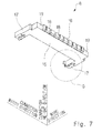
Fig. 7 is a perspective view of the receptacle housing viewed from yet another angle (first embodiment); -
Fig. 8 is an enlarged view of a portion "B" shown inFig. 5 (first embodiment); -
Fig. 9 is an enlarged view of a portion "C" shown inFig. 6 (first embodiment); -
Fig. 10 is an enlarged view of a portion "D" shown inFig. 7 (first embodiment); -
Fig. 11 is a perspective view showing an assistant fitting (first embodiment); -
Fig. 12 is a perspective view of the assistant fitting when viewed from another angle (first embodiment); -
Fig. 13 is an explanatory view showing an assembly of the receptacle connector (first embodiment); -
Fig. 14 is an enlarged view of a portion "E" shown inFig. 13 (first embodiment); -
Fig. 15 is an enlarged view of a portion "A" shown inFig. 3 (first embodiment); -
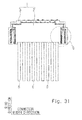
Fig. 16 is a plan view of the receptacle connector (first embodiment); -
Fig. 17 is a perspective view of a plug connector in a state where a plurality of wires are attached to the plug connector (first embodiment); -
Fig. 18 is a perspective view of the plug connector in the state where the plurality of wires are attached to the plug connecter, when viewed from another angle (first embodiment); -
Fig. 19 is a perspective view of a plug contact in a state where a wire is attached to the plug contact (first embodiment); -
Fig. 20 is an enlarged view of a portion "F" shown inFig. 17 (first embodiment); -
Fig. 21 is an image of a sectional view of a claw portion (first embodiment); -
Fig. 22 is a cross-section X of the claw portion specified inFig. 21 (first embodiment); -
Fig. 23 is a cross-section Y of the claw portion specified inFig. 21 (first embodiment); -
Fig. 24 is a cross-section Z of the claw portion specified inFig. 21 (first embodiment); -
Fig. 25 corresponds to a sectional view taken along the line XXV-XXV ofFig. 16 , and shows a state in which a plug connector is mated with a receptacle connector (first embodiment); -
Fig. 26 corresponds to a sectional view taken along the line XXV-XXV ofFig. 16 , and shows a state in which the plug connector is intentionally inclined (first embodiment); -
Fig. 27 is a perspective view showing a modified example of the receptacle connector; -
Fig. 28 is a view showing a modified example of an unlocking surface; -
Fig. 29 is a view corresponding toFig. 5 ofPatent Literature 1; -
Fig. 30 is a view corresponding toFig. 6 ofPatent Literature 1; -
Fig. 31 is a plan view showing the mated state of the wire-to-board connector of the first embodiment; -
Fig. 32 is an enlarged view of a portion "G" shown inFig. 31 ; -
Fig. 33 is a partial perspective view of a plug connector to which a plurality of wires are attached (second embodiment); -
Fig. 34 is a diagram corresponding toFig. 32 (second embodiment); -
Fig. 35 is a partial perspective view of a plug connector to which a plurality of wires are attached (third embodiment); and -
Fig. 36 is a diagram corresponding toFig. 34 (third embodiment) - A first embodiment of the present invention will be described below with reference to
Figs. 1 to 26 . As shown inFigs. 1 and2 , a wire-to-board connector 1 includes aplug connector 2 and areceptacle connector 3. - As shown in
Fig. 2 , theplug connector 2 includes a plurality ofplug contacts 4 and aplug housing 5 that holds the plurality ofplug contacts 4.Wires 6 are respectively attached to theplug contacts 4. - The
receptacle connector 3 includes a plurality ofreceptacle contacts 7, areceptacle housing 8 which holds the plurality ofreceptacle contacts 7, and a pair of assistant fittings 9 (lock pieces). Thereceptacle contacts 7 respectively correspond to theplug contacts 4. Thereceptacle connector 3 is mounted on aconnector mounting surface 10a of a circuit board 10 (board). - As shown in
Fig. 1 , theplug connector 2 is mated with thereceptacle connector 3, thereby allowing theplug contacts 4 to respectively contact thereceptacle contacts 7. - The terms "wire direction", "connector height direction", and "connector width direction" are now defined. The term "wire direction" refers to a direction specified as a longitudinal direction of a
vicinity portion 6a, which is a portion in the vicinity of theplug connector 2 of thewire 6, in a mated state in which theplug connector 2 is mated with thereceptacle connector 3 as shown inFig. 1 . In this embodiment, when the wire-to-board connector 1 is in the mated state, thevicinity portion 6a of eachwire 6 extends along theconnector mounting surface 10a of thecircuit board 10. Accordingly, it can be said that the wire direction is parallel to theconnector mounting surface 10a of thecircuit board 10. In the "wire direction", a direction in which the plurality ofwires 6 are viewed from theplug connector 2 is defined as a connector wire direction and a direction in which theplug connector 2 is viewed from the plurality ofwires 6 is defined as a wire connector direction. The term "connector height direction" refers to a direction orthogonal to theconnector mounting surface 10a of thecircuit board 10. The connector height direction is orthogonal to the wire direction. In the "connector height direction", a direction approaching theconnector mounting surface 10a of thecircuit board 10 is defined as a board approaching direction and a direction separating from theconnector mounting surface 10a of thecircuit board 10 is defined as a board separating direction. The term "connector width direction" refers to a direction orthogonal to the wire direction and the connector height direction. The connector width direction is parallel to theconnector mounting surface 10a of thecircuit board 10. In the "connector width direction", a direction approaching the center of the wire-to-board connector 1 is defined as a "connector width center direction" and a direction separating from the center of the wire-to-board connector 1 is defined as a "connector width anti-center direction". - In the following description, each component of the wire-to-
board connector 1 will be described by using the terms "wire direction", "connector height direction", and "connector width direction", which are defined in the mated state in which theplug connector 2 is mated with thereceptacle connector 3. - As shown in
Figs. 1 and2 , in this embodiment, a mating direction P in which theplug connector 2 is mated with thereceptacle connector 3 is a direction approaching theconnector mounting surface 10a of thecircuit board 10. Specifically, the mating direction P is orthogonal to theconnector mounting surface 10a of thecircuit board 10. Accordingly, the mating direction P coincides with the board approaching direction. - The plurality of
wires 6 are arranged side by side in the connector width direction. Similarly, the plurality ofreceptacle contacts 7 are arranged side by side in the connector width direction. - Next, the
receptacle connector 3 will be described in detail with reference toFigs. 3 to 16 . - As shown in
Figs. 3 and4 , thereceptacle connector 3 includes the plurality ofreceptacle contacts 7, thereceptacle housing 8 which holds the plurality ofreceptacle contacts 7, and the pair ofassistant fittings 9, as described above. - As shown in
Figs. 5 to 7 , thereceptacle housing 8 includes aboard opposing portion 15, a receptaclecontact holding portion 16, and a pair of side portions 17 (lock piece supporting portions). Theboard opposing portion 15, the receptaclecontact holding portion 16, and the pair ofside portions 17, which constitute thereceptacle housing 8, are integrally formed of a material having an insulating property, such as resin. - The
board opposing portion 15 is a flat plate parallel to theconnector mounting surface 10a of thecircuit board 10, and is formed in a rectangular shape elongated in the connector width direction. - The receptacle
contact holding portion 16 is a portion that is connected to an end in the wire connector direction of theboard opposing portion 15, protrudes in the board separating direction, and extends in an elongated shape in the connector width direction. The receptaclecontact holding portion 16 has a plurality of receptaclecontact mounting holes 18 formed therein. Each receptaclecontact mounting hole 18 is a hole for attaching eachreceptacle contact 7 to thereceptacle housing 8. The plurality of receptaclecontact mounting holes 18 are formed at a predetermined interval along the connector width direction. The plurality of receptaclecontact mounting holes 18 are formed between both ends 19 in the connector width direction of the receptaclecontact holding portion 16. Each receptaclecontact mounting hole 18 is formed so as to penetrate the receptaclecontact holding portion 16 in the wire direction. That is, each receptaclecontact mounting hole 18 is formed so as to be opened in the wire connector direction and the connector wire direction. The both ends 19 are walls orthogonal to the wire direction. - The pair of
side portions 17 are respectively connected to the both ends in the connector width direction of theboard opposing portion 15 and the receptaclecontact holding portion 16, and are formed so as to protrude in the connector wire direction. The pair ofside portions 17 is formed to be elongated along the wire direction. The pair ofside portions 17 is formed in a symmetrical shape with respect to the center in the connector width direction of the wire-to-board connector 1. Accordingly, only one of the pair will be described, and the description of the other one of the pair will be omitted. - As shown in
Figs. 8 to 10 , theside portion 17 includes a positioning groove sidepartition wall portion 20, a positioning groove frontpartition wall portion 21, a press-fit groove sidepartition wall portion 22, a press-fit groove frontpartition wall portion 23, a press-fit groove innerpartition wall portion 24, and adisplacement regulating portion 25. - The positioning groove side
partition wall portion 20 is a wall that is connected to an end in the connector width anti-center direction at thecorresponding end 19 of the receptaclecontact holding portion 16, and extends in the connector wire direction. The positioning groove sidepartition wall portion 20 is orthogonal to the connector width direction. - The positioning groove front
partition wall portion 21 is a wall that is connected to an end in the connector wire direction of the positioning groove sidepartition wall portion 20, and extends in the connector width center direction. The positioning groove frontpartition wall portion 21 is orthogonal to the wire direction. - The
end 19 of the receptaclecontact holding portion 16, and the positioning groove sidepartition wall portion 20 and the positioning groove frontpartition wall portion 21 of theside portion 17 constitute apositioning groove 41. Theend 19 of the receptaclecontact holding portion 16 defines a space in the wire connector direction of thepositioning groove 41. The positioning groove sidepartition wall portion 20 defines a space in the connector width anti-center direction of thepositioning groove 41. The positioning groove frontpartition wall portion 21 defines a space in the connector wire direction of thepositioning groove 41. - The press-fit groove side
partition wall portion 22 is a wall that is connected to an end in the connector width anti-center direction of the positioning groove frontpartition wall portion 21, and extends in the connector wire direction. The press-fit groove sidepartition wall portion 22 is orthogonal to the connector width direction. - The press-fit groove front
partition wall portion 23 is a wall that is connected to an end in the connector wire direction of the press-fit groove sidepartition wall portion 22, and extends in the connector width center direction. The press-fit groove frontpartition wall portion 23 is orthogonal to the wire direction. - The press-fit groove inner
partition wall portion 24 is a wall that is connected to an end in the connector width center direction of the press-fit groove frontpartition wall portion 23, and extends in the wire connector direction. The press-fit groove innerpartition wall portion 24 is orthogonal to the connector width direction. - The press-fit groove side
partition wall portion 22 and the press-fit groove innerpartition wall portion 24 constitute a press-fit groove 26. The press-fit groove sidepartition wall portion 22 defines a space in the connector width anti-center direction of the press-fit groove 26. The press-fit groove innerpartition wall portion 24 defines a space in the connector width center direction of the press-fit groove 26. The press-fit groove frontpartition wall portion 23 defines a space in the connector wire direction of the press-fit groove 26. The press-fit groove 26 is opened in the board separating direction. The press-fit groove 26 is formed to be elongated along the wire direction. - An
end 24a in the wire connector direction of the press-fit groove innerpartition wall portion 24 is opposed to the positioning groove frontpartition wall portion 21. A gap "g" is formed between theend 24a of the press-fit groove innerpartition wall portion 24 and the positioning groove frontpartition wall portion 21. - The
displacement regulating portion 25 is connected to an end in the connector wire direction of the press-fit groove innerpartition wall portion 24, and is formed so as to protrude in the connector width center direction. As shown inFigs. 8 to 10 , thedisplacement regulating portion 25 is connected to a side in the board separating direction of the end in the connector wire direction of the press-fit groove innerpartition wall portion 24. Thedisplacement regulating portion 25 includes aninclined guide surface 27, anerect guide surface 28, and a regulatingsurface 29. Theinclined guide surface 27 is a flat surface that is inclined in the board approaching direction toward the connector width center direction on a side in the board separating direction of an end in the connector width center direction of thedisplacement regulating portion 25. Theerect guide surface 28 is a surface that is connected to an edge in the board approaching direction of theinclined guide surface 27 and is orthogonal to the connector width direction. The regulatingsurface 29 is a surface that is connected to an edge in the board approaching direction of theerect guide surface 28 and is orthogonal to the connector height direction. - The pair of
assistant fittings 9 is formed in a symmetrical shape with respect to the center in the connector width direction of the wire-to-board connector 1. Accordingly, only one of the pair will be described, and the description of the other one of the pair will be omitted. - As shown in
Figs. 11 and12 , the assistant fitting 9 includes a lock piece heldportion 30, a lockpiece opposing portion 31, and a lockpiece coupling portion 32. Theassistant fitting 9 is formed by sheet metal bending. - The lock piece held
portion 30 is a portion held by thereceptacle housing 8. The lock piece heldportion 30 is formed so as to extend in the wire direction. The lock piece heldportion 30 is orthogonal to the connector width direction. The lock piece heldportion 30 includes a press-fittedportion 30a and asoldered leg portion 33. The press-fittedportion 30a is formed in a rod shape protruding in the board approaching direction. Thesoldered leg portion 33 is a portion that is soldered to theconnector mounting surface 10a of thecircuit board 10. - The lock
piece opposing portion 31 is formed so as to extend in the wire direction. The lockpiece opposing portion 31 is orthogonal to the connector width direction. The lockpiece opposing portion 31 includes an opposingportion body 34 and aregulated projection 35. - The opposing
portion body 34 is formed to be elongated in the wire direction. The opposingportion body 34 is orthogonal to the connector width direction. The opposingportion body 34 has alock hole 36 which is formed in a substantially rectangular shape when viewed along the connector width anti-center direction. Thelock hole 36 is formed to be elongated in the wire direction. Since thelock hole 36 is formed, alock beam 37 which defines a space in the board separating direction of thelock hole 36 is formed on a side in the board separating direction of thelock hole 36. Thelock beam 37 includes areceptacle lock surface 38, aplug opposing surface 39, and anassembly guide surface 40. Thereceptacle lock surface 38 is a surface that faces in the direction approaching theconnector mounting surface 10a of thecircuit board 10. Thereceptacle lock surface 38 is a flat surface that faces in the board approaching direction. Thereceptacle lock surface 38 is orthogonal to the connector height direction. Thereceptacle lock surface 38 is formed to be elongated in the wire direction. Theplug opposing surface 39 is a flat surface that is connected to an edge in the connector width center direction of thereceptacle lock surface 38 and faces in the connector width center direction. Theplug opposing surface 39 is orthogonal to the connector width direction. Theassembly guide surface 40 is a flat surface that is connected to an edge in the board separating direction of theplug opposing surface 39 and is inclined in the connector width center direction toward the board approaching direction. - The
regulated projection 35 is a portion that is connected to a side in the board approaching direction of an end in the connector wire direction of the opposingportion body 34 and is formed so as to protrude in the connector wire direction. Theregulated projection 35 includes aregulated surface 35a that faces in the board separating direction. Theregulated surface 35a is orthogonal to the connector height direction. - The lock
piece coupling portion 32 is a portion that couples an end in the wire connector direction of the lock piece heldportion 30 with an end in the wire connector direction of the lockpiece opposing portion 31. The lockpiece coupling portion 32 is connected to an end in the wire connector direction of the lock piece heldportion 30, and is formed so as to extend in the connector width center direction. The lockpiece coupling portion 32 is orthogonal to the wire direction. An end in the connector width center direction of the lockpiece coupling portion 32 is connected to an end in the wire connector direction of the lockpiece opposing portion 31. - The
assistant fitting 9 includes the lock piece heldportion 30, the lockpiece opposing portion 31, and the lockpiece coupling portion 32, thereby forming a U-shape when viewed along the board approaching direction. - Next, a method for assembling the
receptacle connector 3 will be described in detail. - First, as shown in
Figs. 3 to 7 , the plurality ofreceptacle contacts 7 are respectively press-fitted into the receptaclecontact mounting holes 17 of the receptaclecontact holding portion 16 of thereceptacle housing 8. A direction in which thereceptacle contacts 7 are respectively press-fitted into the receptaclecontact mounting holes 18 corresponds to the connector wire direction. Eachreceptacle contact 7 is partially exposed in the connector wire direction as shown inFig. 3 and is partially exposed in the board approaching direction as shown inFig. 4 in the state where eachreceptacle contact 7 is attached to thereceptacle housing 8. - Next, as shown in
Fig. 13 , the pair ofassistant fittings 9 are respectively attached to the pair ofside portions 17 of thereceptacle housing 8. Specifically, theassistant fittings 9 are first positioned relative to therespective side portions 17 in such a manner that the lock piece heldportion 30 of eachassistant fitting 9 shown inFig. 14 is inserted into the press-fit groove 26 of thecorresponding side portion 17 of thereceptacle housing 8 and the lockpiece coupling portion 32 of eachassistant fitting 9 is inserted into the gap "g" of thecorresponding side portion 17 of thereceptacle housing 8. After theassistant fittings 9 are positioned relative to therespective side portions 17, theassistant fittings 9 are pushed in the board approaching direction. - Then, the lock piece held
portion 30 of eachassistant fitting 9 is inserted into the press-fit groove 26 of thecorresponding side portion 17 of thereceptacle housing 8. At this time, the press-fittedportion 30a (also seeFigs. 11 and12 ) of the lock piece heldportion 30 of eachassistant fitting 9 is press-fit into a press-fit hole which is not shown and is formed in the press-fit groove 26 of eachside portion 17 of thereceptacle housing 8. The lockpiece coupling portion 32 of eachassistant fitting 9 is inserted into the gap "g" of thecorresponding side portion 17 of thereceptacle housing 8. - The
regulated projection 35 of the lockpiece opposing portion 31 of each assistant fitting 9 passes over theinclined guide surface 27 of thedisplacement regulating portion 25 of thecorresponding side portion 17 of thereceptacle housing 8 in the connector width center direction, while the opposingportion body 34 of the lockpiece opposing portion 31 is elastically displaced in the connector width center direction. Then, theregulated projection 35 slides on theerect guide surface 28 of thedisplacement regulating portion 25 in the board approaching direction. - When each
assistant fitting 9 is further pushed in the board approaching direction, theregulated projection 35 eventually passes over thedisplacement regulating portion 25 in the board approaching direction, and is displaced in the connector width anti-center direction as shown inFig. 15 by the spring restoring force of theassistant fitting 9.Fig. 15 shows a state in which eachassistant fitting 9 is attached to thecorresponding side portion 17 of thereceptacle housing 8. As shown inFig. 15 , eachassistant fitting 9 is supported in a cantilever manner by thecorresponding side portion 17 of thereceptacle housing 8. - In the state shown in
Fig. 15 , thedisplacement regulating portion 25 and theregulated projection 35 face each other in the connector height direction. Specifically, the regulatingsurface 29 of thedisplacement regulating portion 25 shown inFig. 10 and theregulated surface 35a of theregulated projection 35 shown inFig. 11 are opposed to each other in the connector height direction. The opposed relationship between thedisplacement regulating portion 25 and theregulated projection 35 regulates the elastic displacement of the lockpiece opposing portion 31 of eachassistant fitting 9 shown inFig. 15 in the board separating direction. - As shown in
Fig. 16 , a gap "h" is formed between the press-fit groove innerpartition wall portion 24 of eachside portion 17 and the lockpiece opposing portion 31 of eachassistant fitting 9 in the state where eachassistant fitting 9 is attached to thecorresponding side portion 17 of thereceptacle housing 8. Accordingly, thelock beam 37 of the lockpiece opposing portion 31 of eachassistant fitting 9 is elastically displaceable in the connector width anti-center direction. - In this embodiment, "a side surface opposing portion R" corresponds to each
side portion 17 and each assistance fitting 9 of thereceptacle housing 8 as shown inFig. 15 . - Next, the
plug connector 2 will be described in detail with reference toFigs. 17 to 24 . - The
plug connector 2 shown inFigs. 17 and18 includes the plurality ofplug contacts 4 and theplug housing 5 that holds the plurality ofplug contacts 4, as described above. - The
plug housing 5 includes aplug housing body 50, a releasingprojection 51, a pair ofpositioning projections 52, and a pair ofclaw portions 53. - The
plug housing body 50 is a flat body with a small thickness in the connector height direction. Theplug housing body 50 has a rectangular shape when viewed along the board approaching direction, and is formed to be elongated in the connector width direction. Theplug housing body 50 has a plurality of plugcontact mounting holes 54 formed therein. The plurality of plugcontact mounting holes 54 are formed at a predetermined interval along the connector width direction. Each plugcontact mounting hole 54 is formed so as to penetrate theplug housing body 50 in the wire direction. That is, each plugcontact mounting hole 54 is formed so as to be opened in the wire connector direction and the connector wire direction. - The
plug housing body 50 includes a pair ofplug side surfaces 50a serving as a pair of side surfaces of theplug housing body 50. Each of the pair ofplug side surfaces 50a is a flat surface substantially parallel to both of the wire direction and the connector height direction. That is, eachplug side surface 50a is substantially orthogonal to the connector width direction. In this embodiment, the pair ofplug side surfaces 50a is parallel to both of the wire direction and the connector height direction. The pair ofplug side surfaces 50a is orthogonal to the connector width direction. -
Fig. 19 shows theplug contact 4 which is attached to an end of thewire 6. Theplug contact 4 includes a pair ofcontact pieces 4a which contact the correspondingreceptacle contact 7 so as to sandwich thereceptacle contact 7. As shown inFigs. 17 and18 , the plurality ofplug contacts 4 are arranged side by side in the connector width direction. The plurality ofplug contacts 4 are sandwiched by the pair ofplug side surfaces 50a in the connector width direction. In other words, the pair of plug side surfaces 50a sandwich the plurality ofplug contacts 4 in the connector width direction. - As shown in
Figs. 17 and18 , the releasingprojection 51 is connected to a side in the board separating direction of an end in the wire connector direction of theplug housing body 50, and is formed so as to protrude in the wire connector direction. The releasingprojection 51 is formed to be elongated in the connector width direction. - The pair of
positioning projections 52 is formed in a symmetrical shape with respect to the center in the connector width direction of the wire-to-board connector 1. Accordingly, only one of the pair will be described, and the description of the other one of the pair will be omitted. Thepositioning projection 52 is connected to an end in the connector width direction of the end in the wire connector direction of theplug housing body 50, and is formed so as to protrude in the connector width anti-center direction. - The pair of
claw portions 53 is formed in a symmetrical shape with respect to the center in the connector width direction of the wire-to-board connector 1. Accordingly, only one of the pair will be described, and the description of the other one of the pair will be omitted. Theclaw portion 53 is connected to a side in the connector wire direction of theplug side surface 50a, and is formed so as to protrude in the connector width anti-center direction from theplug side surface 50a. Theclaw portion 53 is formed to be elongated in the wire direction. As shown inFig. 20 , theclaw portion 53 has a prism shape with a trapezoidal longitudinal sectional shape, and the side in the wire connector direction of theclaw portion 53 is partially cut off. Theclaw portion 53 includes aplug lock surface 60, amating guide surface 61, aside standing surface 62, anend standing surface 63, and an end inclined surface 64 (inclined surface). - The
plug lock surface 60 is a surface that faces in a direction away from theconnector mounting surface 10a of thecircuit board 10 and is elongated in the wire direction. Theplug lock surface 60 includes alock maintaining surface 65 that is disposed on the side in the connector wire direction, and an unlockingsurface 66 that is disposed on the side in the wire connector direction. Thelock maintaining surface 65 is a flat surface that is connected to theplug side surface 50a and is substantially orthogonal to the connector height direction. The unlockingsurface 66 is a flat surface that is connected to theplug side surface 50a, is inclined in the connector width center direction toward the board separating direction, and is inclined in the connector width center direction toward the wire connector direction. Thelock maintaining surface 65 and the unlockingsurface 66 are connected to each other. Thelock maintaining surface 65 and the unlockingsurface 66 are adjacent to each other in the wire direction. Thelock maintaining surface 65 is disposed on the side in the connector wire direction when viewed from the unlockingsurface 66. That is, the unlockingsurface 66 is disposed on the side in the wire connector direction when viewed from thelock maintaining surface 65. The unlockingsurface 66 is connected to anedge 65a on a side far from theplug side surface 50a of thelock maintaining surface 65. In other words, the unlockingsurface 66 is connected to theedge 65a on a side in the connector width anti-center direction of thelock maintaining surface 65. - The
mating guide surface 61 is a flat surface that faces in the direction approaching theconnector mounting surface 10a of thecircuit board 10 and is elongated in the wire direction. Themating guide surface 61 is inclined in the connector width center direction toward the board approaching direction. - The
side standing surface 62 is a flat surface that faces in the connector width anti-center direction and is elongated in the wire direction. Theside standing surface 62 is orthogonal to the connector width direction. Theside standing surface 62 is connected to theplug lock surface 60 and themating guide surface 61. Theside standing surface 62 is formed between theplug lock surface 60 and themating guide surface 61. - The
end standing surface 63 is a flat surface that is connected to theplug side surface 50a and faces in the connector wire direction. Theend standing surface 63 is orthogonal to the wire direction. Theend standing surface 63 is connected to each of theplug lock surface 60, themating guide surface 61, and theside standing surface 62. - The end inclined
surface 64 is a flat surface that is connected to theplug side surface 50a and faces in the wire connector direction and the connector width anti-center direction. The end inclinedsurface 64 is inclined in the connector width center direction toward the wire connector direction. The end inclinedsurface 64 is connected each of the unlockingsurface 66 of theplug lock surface 60, themating guide surface 61, and theside standing surface 62. - The
plug side surface 50a has a reference plane Q as indicated by an alternate long and two short dashes line inFig. 20 . The reference plane Q is a part of theplug side surface 50a. The reference plane Q is a portion of theplug side surface 50a which is located on a side farther from theconnector mounting surface 10a of thecircuit board 10 than theclaw portion 53. The reference plane Q is a portion of theplug side surface 50a which is located on the side in the board separating direction relative to theclaw portion 53. -
Fig. 21 shows three cross-sections, i.e., a cross-section X, a cross-section Y, and a cross-section Z, of theclaw portion 53. The cross-section X is located on the side in the connector wire direction relative to the cross-section Y. The cross-section Y is located on the side in the connector wire direction relative to the cross-section Z. The cross-section X, the cross-section Y, and the cross-section Z are cross-sections orthogonal to the wire direction. The shape of theclaw portion 53 will be described in more detail by using the cross-section X, the cross-section Y, and the cross-section Z. - In the cross-section X shown in
Fig. 22 , only thelock maintaining surface 65 of theplug lock surface 60 appears. In the cross-section Y shown inFig. 23 , both of thelock maintaining surface 65 and the unlockingsurface 66 of theplug lock surface 60 appear. In other words, in the cross-section Y, thelock maintaining surface 65 and the unlockingsurface 66 are adjacent to each other in the connector width direction. In the cross-section Z shown inFig. 24 , only the unlockingsurface 66 of theplug lock surface 60 appears. In the cross-section X shown inFig. 22 and the cross-section Y shown inFig. 23 , theside standing surface 62 appears. On the other hand, in the cross-section Z shown inFig. 24 , the end inclinedsurface 64 appears instead of theside standing surface 62. - As shown in
Fig. 22 , an angle formed between the reference plane Q and thelock maintaining surface 65 is defined as a lock maintaining angle θ1. As shown inFigs. 23 and24 , an angle formed between the reference plane Q and the unlockingsurface 66 is defined as an unlocking angle θ2. In this embodiment, the lock maintaining angle θ1 is smaller than the unlocking angle θ2. Specifically, the lock maintaining angle θ1 is equal to or smaller than 90 degrees. Preferably, the lock maintaining angle θ1 ranges from 70 to 90 degrees. More preferably, the lock maintaining angle θ1 ranges from 80 to 85 degrees. In this embodiment, the lock maintaining angle θ1 is 85 degrees, and the unlocking angle θ2 is greater than 90 degrees. Preferably, the unlocking angle θ2 ranges from 95 to 165 degrees. More preferably, the unlocking angle θ2 ranges from 120 to 150 degrees. In this embodiment, the unlocking angle θ2 is 135 degrees. - Next, a method for assembling the
plug connector 2 will be described. To assemble theplug connector 2, eachplug contact 4 is attached to an end of thecorresponding wire 6 as shown inFig. 19 , and eachplug contact 4 is inserted into the corresponding plugcontact mounting hole 54 of theplug housing body 50 of theplug housing 5 in the wire connector direction as shown inFig. 17 . As a result, due to an operation of a lance, which is not shown, eachplug contact 4 is inhibited from being disengaged from the corresponding plugcontact mounting hole 54. - Next, a method for mating the wire-to-
board connector 1 will be described. To mate theplug connector 2 with thereceptacle connector 3, thereceptacle connector 3 is preliminarily mounted on theconnector mounting surface 10a of thecircuit board 10 as shown inFig. 2 . Specifically, the soldered leg portion 33 (also seeFig. 4 ) of the lock piece heldportion 30 of eachassistant fitting 9 shown inFig. 11 is soldered to theconnector mounting surface 10a (also seeFig. 2 ) of thecircuit board 10. Further, a soldered leg portion 7a of eachreceptacle contact 7 shown inFig. 4 is soldered to theconnector mounting surface 10a (also seeFig. 2 ) of thecircuit board 10. - Next, as shown in
Fig. 2 , theplug connector 2 is caused to descend in the mating direction P toward thereceptacle connector 3. Then, theplug connector 2 and thereceptacle 3 behave in the following manner. - (1) The pair of
positioning projections 52 of theplug housing 5 shown inFigs. 17 and18 are respectively inserted into the pair ofpositioning grooves 41 shown inFigs. 3 and8 . As a result, the position of theplug connector 2 relative to thereceptacle connector 3 is adjusted. In other words, the pair ofpositioning projections 52 and the pair ofpositioning grooves 41 exert the effect of positioning theplug connector 2 relative to thereceptacle connector 3. Specifically, the effect of positioning theplug connector 2 relative to thereceptacle connector 3 means the effect of positioning theplug connector 2 relative to thereceptacle connector 3 in a direction parallel to theconnector mounting surface 10a of thecircuit board 10. After the mating of the wire-to-board connector 1, the pair ofpositioning projections 52 and the pair ofpositioning grooves 41 exert the retaining effect that inhibits theplug connector 2 from being disengaged from thereceptacle 3 when thewires 6 are pulled in the connector wire direction. - (2) As shown in
Fig. 18 , eachreceptacle contact 7 shown inFig. 3 is inserted between the pair ofcontact pieces 4a (also seeFig. 19 ) which are held by theplug housing 5 of theplug connector 2. This allows the pair ofcontact pieces 4a of eachplug contact 4 to reliably contact the correspondingreceptacle contact 7 so as to sandwich thereceptacle contact 7. - (3) As shown in
Fig. 2 , when theplug connector 2 is caused to descend toward thereceptacle connector 3, each of the pair ofclaw portions 53 of theplug housing 5 shown inFig. 17 is opposed to thelock beam 37 of the lockpiece opposing portion 31 of the corresponding assistant fitting 9 shown inFig. 15 in the connector height direction, due to the effect of positioning theplug connector 2 relative to thereceptacle connector 3, which is exerted by the pair ofpositioning projections 52 shown inFig. 17 and the pair ofpositioning grooves 41 shown inFig. 3 . Then, themating guide surface 61 of theclaw portion 53 shown inFig. 20 contacts theassembly guide surface 40 of thelock beam 37 shown inFig. 15 . In this state, as theplug connector 2 is pushed towardreceptacle connector 3, due to the presence of themating guide surface 61 of theclaw portion 53 shown inFig. 20 and theassembly guide surface 40 of thelock beam 37 shown inFig. 15 , theclaw portion 53 pushes out thelock beam 37 in the connector width anti-center direction, and descends while sliding on theplug opposing surface 39 of thelock beam 37. Eventually, when theclaw portion 53 passes over thelock beam 37, the lockpiece opposing portion 31 is allowed to return in the connector width center direction by the spring restoring force of theassistant fitting 9 and theclaw portion 53 is accommodated in thelock hole 36. As a result, as shown inFig. 25 , theplug lock surface 60 of theclaw portion 53 of theplug housing 5 of theplug connector 2 is opposed in the connector height direction to thereceptacle lock surface 38 of thelock beam 37 of the lockpiece opposing portion 31 of the assistant fitting 9 of thereceptacle connector 3. Theplug lock surface 60 and thereceptacle lock surface 38 are opposed to each other in the connector height direction, thereby inhibiting theconnector 2 from being disengaged from thereceptacle connector 3. - Specifically, in the mated state shown in
Fig. 25 , the plurality ofwires 6 may be raised in the direction away from theconnector mounting surface 10a of thecircuit board 10 due to some operation. When thewires 6 are raised in the direction away from theconnector mounting surface 10a of thecircuit board 10, theplug housing 5 is inclined while being rotated clockwise. When theplug housing 5 is inclined while being rotated clockwise, thelock maintaining surface 65 contacts thereceptacle lock surface 38 in advance of the unlockingsurface 66. In this embodiment, the lock maintaining angle θ1 of thelock maintaining surface 65 is set to be equal to or smaller than 90 degrees. Accordingly, when thewires 6 are raised in the direction away from theconnector mounting surface 10a of thecircuit board 10, the mated state is maintained without releasing the opposed relationship between theplug lock surface 60 and thereceptacle lock surface 38. - On the other hand, as shown in
Fig. 26 , when a claw, a tool, a jig, or the like is hooked on the releasingprojection 51 of theplug housing 5 of theplug connector 2 and theplug connector 2 is intentionally inclined while being rotated counterclockwise so that thewires 6 approach theconnector mounting surface 10a of thecircuit board 10, the unlockingsurface 66 contacts thereceptacle lock surface 38 in advance of thelock maintaining surface 65. In this embodiment, the unlocking angle θ2 of the unlockingsurface 66 is set to be greater than 90 degrees. Accordingly, when theplug connector 2 is intentionally inclined so that thewires 6 approach theconnector mounting surface 10a of thecircuit board 10, theclaw portion 53 pushes out the lockpiece opposing portion 31 of theassistant fitting 9. At this time, since thedisplacement regulating portion 25 is disposed on a side opposite to theconnector mounting surface 10a of thecircuit board 10 with theregulated projection 35 of the lockpiece opposing portion 31 interposed therebetween as shown inFig. 15 , the lockpiece opposing portion 31 is regulated from being elastically displaced in the direction away from theconnector mounting surface 10a of thecircuit board 10. On the other hand, as shown inFig. 16 , the gap "h" is secured between the lockpiece opposing portion 31 and the press-fit groove innerpartition wall portion 24. Accordingly, when theclaw portion 53 pushes out the lockpiece opposing portion 31 of theassistant fitting 9, the lockpiece opposing portion 31 is elastically displaced only in the connector width anti-center direction, without being elastically displaced in the board separating direction. The elastic displacement of the lockpiece opposing portion 31 in the connector width anti-center direction releases the opposed relationship between theplug lock surface 60 and thereceptacle lock surface 38, thereby releasing the mated state of the wire-to-board connector 1. - In sum, the preferred embodiment of the present invention described above has the following features.
- (1) The wire-to-
board connector 1 includes theplug connector 2 and thereceptacle connector 3. Theplug connector 2 includes theplug contacts 4 to which thewires 6 are respectively attached, and theplug housing 5 that holds theplug contacts 4. Thereceptacle connector 3 includes thereceptacle contacts 7 respectively corresponding to theplug contacts 4, and thereceptacle housing 8 that holds thereceptacle contacts 7. Thereceptacle connector 3 is mounted on theconnector mounting surface 10a of the circuit board 10 (board). Theplug connector 2 is mated with thereceptacle connector 3, thereby allowing theplug contacts 4 to respectively contact thereceptacle contacts 7. In the mated state in which theplug connector 2 is mated with thereceptacle connector 3, thevicinity portion 6a which is a portion located in the vicinity of theplug connector 2 of eachwire 6 extends along theconnector mounting surface 10a of thecircuit board 10. The mating direction P in which theplug connector 2 is mated with thereceptacle connector 3 is a direction approaching theconnector mounting surface 10a of thecircuit board 10. Theplug housing 5 includes theplug side surfaces 50a serving as side surfaces of theplug housing 5. Thereceptacle connector 3 includes the side surface opposing portion R that is opposed to the correspondingplug side surface 50a in the mated state. Eachplug side surface 50a is provided with theclaw portion 53 that protrudes toward the side surface opposing portion R. Theclaw portion 53 includes theplug lock surface 60 that faces in the direction away from theconnector mounting surface 10a of thecircuit board 10 and extends in the wire direction which is specified as the longitudinal direction of thevicinity portion 6a in the mated state. Theassistant fitting 9 in the side surface opposing portion R of thereceptacle connector 3 includes thereceptacle lock surface 38 that faces in the direction approaching theconnector mounting surface 10a of thecircuit board 10 and is opposed to theplug lock surface 60 in the mated state. Theplug lock surface 60 includes thelock maintaining surface 65 that is disposed on a side in the connector wire direction which is the direction in which eachwire 6 is viewed from theplug connector 2 in the wire direction, and the unlockingsurface 66 that is disposed on a side in the wire connector direction which is a direction opposite to the connector wire direction. In a cross-section orthogonal to the wire direction, assuming that the angle formed between thelock maintaining surface 65 and the reference plane Q, which is a portion of theplug side surface 50a that is located on a side farther from theconnector mounting surface 10a of thecircuit board 10 than theclaw portion 53, is the lock maintaining angle θ1 and the angle formed between the reference plane Q and the unlockingsurface 66 is the unlocking angle θ2, the lock maintaining angle θ1 is smaller than the unlocking angle θ2. - Specifically, when the
wires 6 are raised in the direction away from theconnector mounting surface 10a of thecircuit board 10 and theplug connector 2 is inclined, thelock maintaining surface 65 contacts thereceptacle lock surface 38 in advance of the unlockingsurface 66. On the other hand, when theplug connector 2 is intentionally inclined so that thewires 6 approach theconnector mounting surface 10a of thecircuit board 10, the unlockingsurface 66 contacts thereceptacle lock surface 38 in advance of thelock maintaining surface 65. Thus, according to the structure described above, when thewires 6 are raised in the direction away from theconnector mounting surface 10a of thecircuit board 10, the mated state is easily maintained without releasing the opposed relationship between theplug lock surface 60 and thereceptacle lock surface 38, and when theplug connector 2 is intentionally inclined so that thewires 6 approach theconnector mounting surface 10a of thecircuit board 10, the opposed relationship between theplug lock surface 60 and thereceptacle lock surface 38 is released, thereby facilitating the release of the mated state. Consequently, the wire-to-board connector 1 capable of maintaining the mated state even when thewires 6 are raised in the direction away from theconnector mounting surface 10a of thecircuit board 10 and capable of intentionally releasing the mated state is achieved. - The
receptacle lock surface 38 is formed in the assistant fitting 9 of the side surface opposed portion R in this embodiment, but instead may be formed in theside portion 17 of the side surface opposed portion R. In a modified example shown inFig. 27 , the side surface opposing portion R does not include theassistant fitting 9. The side surface opposing portion R is formed of theside portion 17. Thereceptacle lock surface 38 is formed in theside portion 17. - (2) The unlocking angle θ2 is greater than 90 degrees. According to the structure described above, when the
plug connector 2 is intentionally inclined so that thewires 6 approach theconnector mounting surface 10a of thecircuit board 10, the opposed relationship between theplug lock surface 60 and thereceptacle lock surface 38 is released more easily. - (3) The lock maintaining angle θ1 is equal to or smaller than 90 degrees. According to the structure described above, when the
wires 6 are raised in the direction away from theconnector mounting surface 10a of thecircuit board 10, the opposed relationship between theplug lock surface 60 and thereceptacle lock surface 38 is less likely to be released. - (4) The unlocking
surface 66 is inclined so as to approach theplug side surface 50a in the wire connector direction. According to the structure described above, when the plug connector is intentionally inclined so that the wires approach the connector mounting surface of the board, the opposed relationship between the plug lock surface and the receptacle lock surface can be released more smoothly. - (5) The unlocking
surface 66 is connected to theedge 65a of thelock maintaining surface 65 on a side far from theplug side surface 50a. According to the structure described above, when theplug connector 2 is intentionally inclined so that thewires 6 approach theconnector mounting surface 10a of thecircuit board 10 and the opposed relationship between theplug lock surface 60 and thereceptacle lock surface 38 is released, thereceptacle lock surface 38 is prevented from being caught on the boundary between the unlockingsurface 66 and thelock maintaining surface 65. - (6) The end inclined surface 64 (inclined surface) that is inclined so as to approach the
plug side surface 50a in the wire connector direction is formed at an end in the wire connector direction of theclaw portion 53. The end inclinedsurface 64 is connected to the unlockingsurface 66. According to the structure described above, when theplug connector 2 is intentionally inclined so that thewires 6 approach theconnector mounting surface 10a of thecircuit board 10, the opposed relationship between theplug lock surface 60 and thereceptacle lock surface 38 can be released more smoothly. - (7) The side surface opposing portion R includes the side portion 17 (lock piece supporting portion) and the assistant fitting 9 (lock piece) which is supported by the
side portion 17. Theassistant fitting 9 is formed in a cantilever shape including the lock piece heldportion 30 which is held by theside portion 17, and the lockpiece opposing portion 31 which is opposed to theplug side surface 50a. The lockpiece opposing portion 31 is elastically displaceable in the direction away from theplug side surface 50a. Thereceptacle lock surface 38 is formed in the lockpiece opposing portion 31. According to the structure described above, when theplug connector 2 is intentionally inclined so that thewires 6 approach theconnector mounting surface 10a of thecircuit board 10, thereceptacle lock surface 38 is pushed out by the unlockingsurface 66 in the direction away from theplug side surface 50a, so that the opposed relationship between theplug lock surface 60 and thereceptacle lock surface 38 can be released more smoothly. - (8) The
side portion 17 of the side surface opposing portion R includes thedisplacement regulating portion 25 that is disposed on the side opposite to theconnector mounting surface 10a of thecircuit board 10 with theregulated projection 35 of the lockpiece opposing portion 31 interposed therebetween, thereby regulating the lockpiece opposing portion 31 from being elastically displaced in the direction away from theconnector mounting surface 10a of thecircuit board 10. According to the structure described above, when theplug connector 2 is intentionally inclined so that thewires 6 approach theconnector mounting surface 10a of thecircuit board 10, thereceptacle lock surface 38 is rapidly pushed out by the unlockingsurface 66 in the direction away from theplug side surface 50a.
In this embodiment, thedisplacement regulating portion 25 is formed at theside portion 17 of the side surface opposing portion R, but instead may be formed at, for example, the lock piece heldportion 30 of the assistant fitting 9 of the side surface opposing portion R. - (9) The lock piece held
portion 30 and the lockpiece opposing portion 31 are formed so as to extend in the wire direction. The above-mentioned structure contributes to a reduction in the height of the wire-to-board connector 1. - (10) An end in the wire connector direction of the lock piece held
portion 30 and an end in the wire connector direction of the lockpiece opposing portion 31 are coupled together. - (11) The
plug housing 5 is provided with the releasingprojection 51 that allows theplug connector 2 to be inclined so that thewires 6 approach theconnector mounting surface 10a of thecircuit board 10. - (12) The releasing
projection 51 is formed so as to protrude in the wire connector direction from an end in the wire connector direction of theplug housing 5. - The preferred embodiment of the present invention described above can be modified in the following manner, for example.
- In the embodiment described above, the unlocking
surface 66 of theplug lock surface 60 is formed as a flat surface, but instead may be formed as a curved surface that is curved so as to approach theconnector mounting surface 10a of thecircuit board 10 in a direction away from theplug side surface 50a as shown inFig. 28. Fig. 28 shows a cross-sectional shape of the curved unlockingsurface 66 as indicated by a hatched area. Also in this case, the wire-to-board connector 1 capable of maintaining the mated state even when thewires 6 are raised in the direction away from theconnector mounting surface 10a of thecircuit board 10 and capable of intentionally releasing the mated state is achieved. - Upon assembly of the
receptacle connector 3, theassistant fittings 9 are positioned relative to therespective side portions 17, and theassistant fittings 9 are pushed in the board approaching direction. However, instead, theassistant fittings 9 may be pushed in the board separating direction. That is, upon attachment of theassistant fittings 9 to therespective side portions 17, the attachment direction is not limited to the board approaching direction. - A second embodiment of the present invention will be described below with reference to
Figs. 31 to 34 . Here, differences between this embodiment and the first embodiment will be mainly described, while a repeat of previous descriptions is omitted as appropriate. Components corresponding to the components of the first embodiment described above are denoted by the same reference numerals as a rule. -
Fig. 31 shows the mated state of the wire-to-board connector 1.Fig. 32 is an enlarged view of a portion "G" shown inFig. 31 . - As shown in
Fig. 32 , the lockpiece opposing portion 31 of the assistant fitting 9 of thereceptacle connector 3 is supported in a cantilever manner. Accordingly, anend 31 a which corresponds to the bottom of the lockpiece opposing portion 31 and is located on the side of the lockpiece coupling portion 32 of the lockpiece opposing portion 31 is less likely to be elastically displaced in the connector width anti-center direction. If theplug housing body 50 of theplug housing 5 of theplug connector 2 happens to contact theend 31a located on the side of the lockpiece coupling portion 32 of the lock piece opposedportion 31 of the assistant fitting 9 of thereceptacle connector 3 when theplug connector 2 is mated with thereceptacle connector 3, the mating of theplug connector 2 with thereceptacle connector 3 is considerably inhibited because theend 31a is less likely to be elastically displaced in the connector width anti-center direction as described above. - To avoid such a problem, in the first embodiment described above, a gap "i" is left between the
plug side surface 50a of theplug housing body 50 of theplug housing 5 of theplug connector 2 and the lockpiece opposing portion 31 of the assistant fitting 9 of thereceptacle connector 3 in the mated state of the wire-to-board connector 1. - However, due to the presence of the gap "i", the movement of the
plug housing 5 of theplug connector 2 in the connector width direction is allowed within thereceptacle connector 3 in the mated state of the wire-to-board connector 1 shown inFig. 32 . When theplug housing 5 of theplug connector 2 is moved in the connector width direction within thereceptacle connector 3, the opposed relationship in the connector height direction between thereceptacle lock surface 38 of the lockpiece opposing portion 31 of the assistant fitting 9 shown inFig. 15 and thelock maintaining surface 65 of theplug lock surface 60 of theclaw portion 53 shown inFig. 20 is weakened. This results in a problem that theplug connector 2 is liable to be disengaged from thereceptacle connector 3. - As shown in
Fig. 33 , in this embodiment, eachplug side surface 50a of theplug housing body 50 of theplug housing 5 of theplug connector 2 is provided with an overhangingportion 80 which projects toward the assistant fitting 9 (lock piece) of the side surface opposing portion R. That is, the overhangingportion 80 is formed so as to protrude in the connector width anti-center direction from the correspondingplug side surface 50a of theplug housing body 50. In the mated state of the wire-to-board connector 1 shown inFig. 34 , the overhangingportion 80 is in contact with an elastically displaceable portion of the lockpiece opposing portion 31. According to the structure described above, in the mated state of the wire-to-board connector 1, the movement of theplug housing 5 of theplug connector 2 in the connector width direction within thereceptacle connector 3 is suppressed by an elastic force N of the lockpiece opposing portion 31 of the assistant fitting 9 of thereceptacle connector 3 in the connector width center direction. As a result, the opposed relationship in the connector height direction between thereceptacle lock surface 38 of the lockpiece opposing portion 31 of the assistant fitting 9 shown inFig. 15 and thelock maintaining surface 65 of theplug lock surface 60 of theclaw portion 53 shown inFig. 20 is maintained, thereby preventing theplug connector 2 from being easily disengaged from thereceptacle connector 3. - Specifically, as shown in
Fig. 33 , theplug housing 5 of theplug connector 2 includes a pair of overhangingportions 80 in addition to theplug housing body 50, the releasingprojection 51, the pair ofpositioning projections 52, and the pair ofclaw portions 53. Each overhangingportion 80 is formed so as to protrude in the connector width anti-center direction from the correspondingplug side surface 50a. The overhangingportion 80 is formed at a location as far as possible from thecorresponding positioning projection 52. The overhangingportion 80 includes an overhangingsurface 80a that faces in the connector width anti-center direction. The overhangingsurface 80a is orthogonal to the connector width direction. Since the overhangingportions 80 are respectively formed on the plug side surfaces 50a of theplug housing body 50, the overhangingsurface 80a of each overhangingportion 80 can be regarded as a part of the plug side surfaces 50a of theplug housing body 50. The overhangingportions 80 are respectively provided with theclaw portions 53. Specifically, eachclaw portion 53 is formed on the overhangingsurface 80a of the corresponding overhangingportion 80. Theclaw portion 53 is formed so as to protrude in the connector width anti-center direction from the overhangingsurface 80a of the corresponding overhangingportion 80. - Since each overhanging
portion 80 is formed at a location as far as possible from thecorresponding positioning projection 52 as shown inFig. 33 , the overhangingportion 80 is apart from theend 31a of the lockpiece opposing portion 31 in the connector wire direction in the mated state of the wire-to-board connector 1 as shown inFig. 34 . As a result, in the mated state of the wire-to-board connector 1, the overhangingportion 80 is constantly in contact with the elastically displaceable portion of the lockpiece opposing portion 31. On the other hand, the above-mentioned gap "i" still exists between theplug side surface 50a and the vicinity of theend 31a of the lockpiece opposing portion 31. Accordingly, also in this embodiment in which the overhangingportions 80 are provided, it is possible to effectively prevent theplug housing body 50 of theplug housing 5 of theplug connector 2 from contacting theend 31a located on the side of the lockpiece coupling portion 32 of the lock piece opposedportion 31 of the assistant fitting 9 of thereceptacle connector 3 when theplug connector 2 is mated with thereceptacle connector 3, as in the first embodiment described above. Therefore, the mating of theplug connector 2 with thereceptacle connector 3 is not inhibited. - Next, a third embodiment of the present invention will be described with reference to
Figs. 35 and36 . Here, differences between this embodiment and the second embodiment will be mainly described, while a repeat of previous descriptions is omitted as appropriate. Components corresponding to the components of the second embodiment described above are denoted by the same reference numerals as a rule. - As shown in
Fig. 35 , in this embodiment, the overhangingsurface 80a of each overhangingportion 80 includes a first overhangingsurface 80b and asecond overhanging surface 80c. Thefirst overhanging surface 80b is connected to an end in the connector wire direction of the second overhangingsurface 80c. That is, the second overhangingsurface 80c is connected to an end in the wire connector direction of the first overhangingsurface 80b. Thefirst overhanging surface 80b faces in the connector width anti-center direction. Thefirst overhanging surface 80b is orthogonal to the connector width direction. Thefirst overhanging surface 80b is connected to an end in the connector wire direction of thelock maintaining surface 65 of theplug lock surface 60 of theclaw portion 53. Thesecond overhanging surface 80c is inclined in the connector width center direction toward the wire connector direction. - In this structure, as shown in
Fig. 36 , when theplug connector 2 is mated with thereceptacle connector 3, only the first overhangingsurface 80b of the overhangingportion 80 is constantly in contact with the lockpiece opposing portion 31, and the second overhangingsurface 80c of the overhangingportion 80 does not contact the lockpiece opposing portion 31. Further, the first overhangingsurface 80b is connected to the end in the connector wire direction of thelock maintaining surface 65 of theclaw portion 53. Accordingly, regardless of how much the lockpiece opposing portion 31 is elastically displaced in the connector width anti-center direction due to the contact between the overhangingportion 80 and the lockpiece opposing portion 31, the elastic displacement has no influence on the opposed relationship in the connector height direction between thereceptacle lock surface 38 of the lockpiece opposing portion 31 of the assistant fitting 9 shown inFig. 15 and thelock maintaining surface 65 of theplug lock surface 60 of theclaw portion 53 shown inFig. 20 . - This application is based upon and claims the benefit of priority from Japanese patent application No.
2012-072085, filed on March 27, 2012 2012-247408, filed on November 9, 2012 -
- 1
- WIRE-TO-BOARD CONNECTOR
- 2
- PLUG CONNECTOR
- 3
- RECEPTACLE CONNECTOR
- 4
- PLUG CONTACT
- 4a
- CONTACT PIECE
- 5
- PLUG HOUSING
- 6
- WIRE
- 6a
- VICINITY PORTION
- 7
- RECEPTACLE CONTACT
- 7a
- SOLDERED LEG PORTION
- 8
- RECEPTACLE HOUSING
- 9
- ASSISTANT FITTING (LOCK PIECE)
- 10
- CIRCUIT BOARD (BOARD)
- 10a
- CONNECTOR MOUNTING SURFACE
- 15
- BOARD OPPOSING PORTION
- 16
- RECEPTACLE CONTACT HOLDING PORTION
- 17
- SIDE PORTION (LOCK PIECE SUPPORTING PORTION)
- 18
- RECEPTACLE CONTACT MOUNTING HOLE
- 19
- END
- 20
- POSITIONING GROOVE SIDE PARTITION WALL PORTION
- 21
- POSITIONING GROOVE FRONT PARTITION WALL PORTION
- 22
- PRESS-FIT GROOVE SIDE PARTITION WALL PORTION
- 23
- PRESS-FIT GROOVE FRONT PARTITION WALL PORTION
- 24
- PRESS-FIT GROOVE INNER PARTITION WALL PORTION
- 24a
- END
- 25
- DISPLACEMENT REGULATING PORTION
- 26
- PRESS-FIT GROOVE
- 27
- INCLINED GUIDE SURFACE
- 28
- ERECT GUIDE SURFACE
- 29
- REGULATING SURFACE
- 30
- LOCK PIECE HELD PORTION
- 30a
- PRESS-FITTED PORTION
- 31
- LOCK PIECE OPPOSING PORTION
- 31a
- END
- 32
- LOCK PIECE COUPLING PORTION
- 33
- SOLDERED LEG PORTION
- 34
- OPPOSING PORTION BODY
- 35
- REGULATED PROJECTION
- 35a
- REGULATED SURFACE
- 36
- LOCK HOLE
- 37
- LOCK BEAM
- 38
- RECEPTACLE LOCK SURFACE
- 39
- PLUG OPPOSING SURFACE
- 40
- ASSEMBLY GUIDE SURFACE
- 41
- POSITIONING GROOVE
- 50
- PLUG HOUSING BODY
- 50a
- PLUG SIDE SURFACE
- 51
- RELEASING PROJECTION
- 52
- POSITIONING PROJECTION
- 53
- CLAW PORTION
- 54
- PLUG CONTACT MOUNTING HOLE
- 60
- PLUG LOCK SURFACE
- 61
- MATING GUIDE SURFACE
- 62
- SIDE STANDING SURFACE
- 63
- END STANDING SURFACE
- 64
- END INCLINED SURFACE (INCLINED SURFACE)
- 65
- LOCK MAINTAINING SURFACE
- 65a
- EDGE
- 66
- UNLOCKING SURFACE
- 80
- OVERHANGING PORTION
- 80a
- OVERHANGING SURFACE
- 80b
- FIRST OVERHANGING SURFACE
- 80c
- SECOND OVERHANGING SURFACE
- h
- GAP
- i
- GAP
- g
- GAP
- N
- ELASTIC FORCE
- P
- MATING DIRECTION
- Q
- REFERENCE PLANE
- R
- SIDE SURFACE OPPOSING PORTION
- X
- CROSS-SECTION
- Y
- CROSS-SECTION
- Z
- CROSS-SECTION
- θ1
- LOCK MAINTAINING ANGLE
- θ2
- UNLOCKING ANGLE
Claims (14)
- A wire-to-board connector comprising:a plug connector including a plug contact to which a wire is attached, and a plug housing that holds the plug contact; anda receptacle connector that is mounted on a connector mounting surface of a board and includes a receptacle contact corresponding to the plug contact, and a receptacle housing that holds the receptacle contact, the plug connector being mated with the receptacle connector to thereby allow the plug contact to contact the receptacle contact, whereinin a mated state in which the plug connector is mated with the receptacle connector, a vicinity portion of the wire, the vicinity portion being located in the vicinity of the plug connector, extends along the connector mounting surface of the board,a mating direction in which the plug connector is mated with the receptacle connector is a direction approaching the connector mounting surface of the board,the plug housing includes a plug side surface as a side surface of the plug housing,the receptacle connector includes a side surface opposing portion that is opposed to the plug side surface in the mated state,the plug side surface is provided with a claw portion projecting toward the side surface opposing portion,the claw portion includes a plug lock surface that faces in a direction away from the connector mounting surface of the board and extends in a wire direction specified as a longitudinal direction of the vicinity portion in the mated state,the side surface opposing portion of the receptacle connector includes a receptacle lock surface that faces in a direction approaching the connector mounting surface of the board and is opposed to the plug lock surface in the mated state,the plug lock surface includes a lock maintaining surface disposed on a side in a connector wire direction in which the wire is viewed from the plug connector in the wire direction, and an unlocking surface disposed on a side in a wire connector direction which is opposite to the connector wire direction, andin a cross-section orthogonal to the wire direction, assuming that an angle formed between the lock maintaining surface and a reference plane that is a portion of the plug side surface located on a side farther from the connector mounting surface of the board than the claw portion is a lock maintaining angle θ1 and an angle formed between the reference plane and the unlocking surface is an unlocking angle θ2, the lock maintaining angle θ1 is smaller than the unlocking angle θ2.
- The wire-to-board connector according to Claim 1, wherein the unlocking angle θ2 is greater than 90 degrees.
- The wire-to-board connector according to Claim 1 or 2, wherein the lock maintaining angle θ1 is equal to or smaller than 90 degrees.
- The wire-to-board connector according to any one of Claims 1 to 3, wherein the unlocking surface is inclined so as to approach the plug side surface in the wire connector direction.
- The wire-to-board connector according to any one of Claims 1 to 3, wherein the unlocking surface is connected to an edge of the lock maintaining surface on a side far from the plug side surface.
- The wire-to-board connector according to any one of Claims 1 to 5, wherein
at an end in the wire connector direction of the claw portion, an inclined surface that is inclined so as to approach the plug side surface in the wire connector direction is formed, and
the inclined surface is connected to the unlocking surface. - The wire-to-board connector according to any one of Claims 1 to 6, wherein
the side surface opposing portion includes a lock piece supporting portion and a lock piece that is supported by the lock piece supporting portion,
the lock piece is formed in a cantilever shape including a lock piece held portion that is held by the lock piece supporting portion, and a lock piece opposing portion that is opposed to the plug side surface,
the lock piece opposing portion is elastically displaceable in a direction away from the plug side surface, and
the receptacle lock surface is formed in the lock piece opposing portion. - The wire-to-board connector according to Claim 7, wherein the side surface opposing portion includes a displacement regulating portion that is disposed on a side opposite to the connector mounting surface of the board with the lock piece opposing portion interposed therebetween, thereby regulating the lock piece opposing portion from being elastically displaced in a direction away from the connector mounting surface of the board.
- The wire-to-board connector according to Claim 7 or 8, wherein the lock piece held portion and the lock piece opposing portion are formed so as to extend in the wire direction.
- The wire-to-board connector according to Claim 9, wherein an end in the wire connector direction of the lock piece held portion is coupled with an end in the wire connector direction of the lock piece opposing portion.
- The wire-to-board connector according to any one of Claims 1 to 10, wherein the plug housing is provided with a releasing projection that allows the plug connector to be inclined in such a manner that the wire approaches the connector mounting surface of the board.
- The wire-to-board connector according to Claim 11, wherein the releasing projection is formed so as to protrude in the wire connector direction from an end in the wire connector direction of the plug housing.
- A wire-to-board connector comprising:a plug connector including a plug contact to which a wire is attached, and a plug housing that holds the plug contact; anda receptacle connector that is mounted on a connector mounting surface of a board and includes a receptacle contact corresponding to the plug contact, and a receptacle housing that holds the receptacle contact, the plug connector being mated with the receptacle connector to thereby allow the plug contact to contact the receptacle contact, whereinin a mated state in which the plug connector is mated with the receptacle connector, a vicinity portion of the wire, the vicinity portion being located in the vicinity of the plug connector, extends along the connector mounting surface of the board,a mating direction in which the plug connector is mated with the receptacle connector is a direction approaching the connector mounting surface of the board,the plug housing includes a plug side surface as a side surface of the plug housing,the receptacle connector includes a side surface opposing portion that is opposed to the plug side surface in the mated state,the plug side surface is provided with a claw portion projecting toward the side surface opposing portion,the claw portion includes a plug lock surface that faces in a direction away from the connector mounting surface of the board and extends in a wire direction specified as a longitudinal direction of the vicinity portion in the mated state,the side surface opposing portion of the receptacle connector includes a receptacle lock surface that faces in a direction approaching the connector mounting surface of the board and is opposed to the plug lock surface in the mated state,the plug lock surface includes a lock maintaining surface disposed on a side in a connector wire direction in which the wire is viewed from the plug connector in the wire direction, and an unlocking surface disposed on a side in a wire connector direction which is opposite to the connector wire direction, andthe unlocking surface is formed to be curved so as to approach the connector mounting surface of the board in a direction away from the plug side surface.
- A wire-to-board connector comprising:a plug connector including a plug contact to which a wire is attached, and a plug housing that holds the plug contact; anda receptacle connector that is mounted on a connector mounting surface of a board and includes a receptacle contact corresponding to the plug contact, and a receptacle housing that holds the receptacle contact, the plug connector being mated with the receptacle connector to thereby allow the plug contact to contact the receptacle contact, whereinin a mated state in which the plug connector is mated with the receptacle connector, a vicinity portion of the wire, the vicinity portion being located in the vicinity of the plug connector, extends along the connector mounting surface of the board,a mating direction in which the plug connector is mated with the receptacle connector is a direction approaching the connector mounting surface of the board,the plug housing includes a plug side surface as a side surface of the plug housing,the receptacle connector includes a side surface opposing portion that is opposed to the plug side surface in the mated state,the plug side surface is provided with a claw portion projecting toward the side surface opposing portion,the claw portion includes a plug lock surface that faces in a direction away from the connector mounting surface of the board and extends in a wire direction specified as a longitudinal direction of the vicinity portion in the mated state,the side surface opposing portion of the receptacle connector includes a receptacle lock surface that faces in a direction approaching the connector mounting surface of the board and is opposed to the plug lock surface in the mated state,the plug lock surface includes a lock maintaining surface disposed on a side in a connector wire direction in which the wire is viewed from the plug connector in the wire direction, and an unlocking surface disposed on a side in a wire connector direction which is opposite to the connector wire direction,in a cross-section orthogonal to the wire direction, assuming that an angle formed between the lock maintaining surface and a reference plane that is a portion of the plug side surface located on a side farther from the connector mounting surface of the board than the claw portion is a lock maintaining angle θ1 and an angle formed between the reference plane and the unlocking surface is an unlocking angle θ2, the lock maintaining angle θ1 is smaller than the unlocking angle θ2,the side surface opposing portion includes a lock piece supporting portion and a lock piece that is supported by the lock piece supporting portion,the lock piece is formed in a cantilever shape including a lock piece held portion that is held by the lock piece supporting portion, and a lock piece opposing portion that is opposed to the plug side surface,the lock piece opposing portion is elastically displaceable in a direction away from the plug side surface, andthe plug side surface of the plug housing is provided with an overhanging portion projecting toward the lock piece of the side surface opposing portion, and the overhanging portion is in contact with an elastically displaceable portion of the lock piece opposing portion in the mated state.
Applications Claiming Priority (3)
| Application Number | Priority Date | Filing Date | Title |
|---|---|---|---|
| JP2012072085 | 2012-03-27 | ||
| JP2012247408 | 2012-11-09 | ||
| PCT/JP2013/000707 WO2013145527A1 (en) | 2012-03-27 | 2013-02-08 | Electric wire-to-substrate connector |
Publications (3)
| Publication Number | Publication Date |
|---|---|
| EP2833484A1 true EP2833484A1 (en) | 2015-02-04 |
| EP2833484A4 EP2833484A4 (en) | 2015-10-14 |
| EP2833484B1 EP2833484B1 (en) | 2016-07-27 |
Family
ID=49258854
Family Applications (1)
| Application Number | Title | Priority Date | Filing Date |
|---|---|---|---|
| EP13769589.6A Active EP2833484B1 (en) | 2012-03-27 | 2013-02-08 | Electric wire-to-substrate connector |
Country Status (6)
| Country | Link |
|---|---|
| US (1) | US9240653B2 (en) |
| EP (1) | EP2833484B1 (en) |
| JP (1) | JP5801473B2 (en) |
| KR (1) | KR101655207B1 (en) |
| CN (1) | CN104221227B (en) |
| WO (1) | WO2013145527A1 (en) |
Cited By (1)
| Publication number | Priority date | Publication date | Assignee | Title |
|---|---|---|---|---|
| EP2876743A4 (en) * | 2012-07-19 | 2016-02-17 | Japan Aviation Electron | Connector between cable and substrate |
Families Citing this family (11)
| Publication number | Priority date | Publication date | Assignee | Title |
|---|---|---|---|---|
| CN103811910B (en) * | 2014-02-07 | 2018-03-09 | 连展科技电子(昆山)有限公司 | Electric connector |
| CN206004039U (en) | 2016-08-04 | 2017-03-08 | 富士康(昆山)电脑接插件有限公司 | Electric connector and combinations thereof |
| TWD192835S (en) * | 2018-01-22 | 2018-09-11 | 唐虞企業股份有限公司 | Board end connector |
| TWD192834S (en) * | 2018-01-22 | 2018-09-11 | 唐虞企業股份有限公司 | Board end connector housing |
| TWD192841S (en) * | 2018-01-29 | 2018-09-11 | 唐虞企業股份有限公司 | Part of the line end connector |
| TWD192840S (en) * | 2018-01-29 | 2018-09-11 | 唐虞企業股份有限公司 | Part of the wire end connector housing |
| JP6658798B2 (en) * | 2018-06-05 | 2020-03-04 | 第一精工株式会社 | Electrical connector and connector device |
| TWM601912U (en) * | 2019-03-26 | 2020-09-21 | 英屬開曼群島商鴻騰精密科技股份有限公司 | Receptacle connector |
| CN210326329U (en) | 2019-06-21 | 2020-04-14 | 重庆市鸿腾科技有限公司 | Socket connector and plug connector connected with same |
| US11374358B2 (en) | 2019-07-01 | 2022-06-28 | Amphenol Fci Asia Pte. Ltd. | Wire to board connector with low height |
| TWM594289U (en) * | 2019-09-10 | 2020-04-21 | 禾昌興業股份有限公司 | Connector |
Family Cites Families (20)
| Publication number | Priority date | Publication date | Assignee | Title |
|---|---|---|---|---|
| US5545051A (en) | 1995-06-28 | 1996-08-13 | The Whitaker Corporation | Board to board matable assembly |
| JP2003142208A (en) | 2001-11-07 | 2003-05-16 | Sumitomo Wiring Syst Ltd | Connector |
| JP4082512B2 (en) * | 2004-03-31 | 2008-04-30 | エフシーアイ アジア テクノロジー ピーティーイー リミテッド | Vertical mating connector |
| JP4020907B2 (en) | 2004-11-01 | 2007-12-12 | 日本圧着端子製造株式会社 | Socket contact |
| JP4115983B2 (en) * | 2004-11-01 | 2008-07-09 | 日本圧着端子製造株式会社 | Blade contact |
| JP4579021B2 (en) * | 2005-03-23 | 2010-11-10 | ヒロセ電機株式会社 | Electrical connector |
| JP4605785B2 (en) * | 2005-11-30 | 2011-01-05 | ヒロセ電機株式会社 | Electrical connector |
| US7261580B1 (en) * | 2006-04-27 | 2007-08-28 | General Electric Company | Cable connector |
| US7329158B1 (en) * | 2006-06-30 | 2008-02-12 | Yazaki North America, Inc. | Push-lock terminal connection assembly |
| US7641500B2 (en) * | 2007-04-04 | 2010-01-05 | Fci Americas Technology, Inc. | Power cable connector system |
| US7497715B2 (en) * | 2007-06-11 | 2009-03-03 | Hon Hai Precision Ind. Co., Ltd. | Cable connector assembly for solar device |
| JP5134415B2 (en) * | 2008-03-31 | 2013-01-30 | 日本圧着端子製造株式会社 | Socket connector |
| JP4678887B2 (en) * | 2009-01-22 | 2011-04-27 | 日本航空電子工業株式会社 | Connector assembly |
| JP4972174B2 (en) * | 2009-04-16 | 2012-07-11 | ヒロセ電機株式会社 | Electrical connector assembly |
| JP2012003874A (en) * | 2010-06-15 | 2012-01-05 | Fujitsu Ltd | Connector, receptacle connector and plug connector |
| JP2012072085A (en) | 2010-09-29 | 2012-04-12 | Shiseido Co Ltd | Oil-in-water type emulsified cosmetic |
| JP4885320B1 (en) * | 2011-03-23 | 2012-02-29 | 日本航空電子工業株式会社 | Wire-to-board connector |
| TWM410379U (en) * | 2011-04-01 | 2011-08-21 | Cheng Uei Prec Ind Co Ltd | Wire to board connector assembly |
| KR101064655B1 (en) | 2011-05-25 | 2011-09-15 | 한국지질자원연구원 | Excitation device and downhole seismic test method using it |
| CN104092051A (en) * | 2011-11-23 | 2014-10-08 | 3M创新有限公司 | Electrical cable connector and latching electrical cable connector assembly |
-
2013
- 2013-02-08 US US14/386,630 patent/US9240653B2/en active Active
- 2013-02-08 JP JP2014507359A patent/JP5801473B2/en active Active
- 2013-02-08 CN CN201380014702.9A patent/CN104221227B/en active Active
- 2013-02-08 WO PCT/JP2013/000707 patent/WO2013145527A1/en active Application Filing
- 2013-02-08 KR KR1020147025787A patent/KR101655207B1/en active IP Right Grant
- 2013-02-08 EP EP13769589.6A patent/EP2833484B1/en active Active
Cited By (2)
| Publication number | Priority date | Publication date | Assignee | Title |
|---|---|---|---|---|
| EP2876743A4 (en) * | 2012-07-19 | 2016-02-17 | Japan Aviation Electron | Connector between cable and substrate |
| US9748677B2 (en) | 2012-07-19 | 2017-08-29 | Japan Aviation Electronics Industry, Ltd. | Wire-to-board connector |
Also Published As
| Publication number | Publication date |
|---|---|
| JPWO2013145527A1 (en) | 2015-12-10 |
| JP5801473B2 (en) | 2015-10-28 |
| WO2013145527A1 (en) | 2013-10-03 |
| US9240653B2 (en) | 2016-01-19 |
| KR20140138729A (en) | 2014-12-04 |
| EP2833484B1 (en) | 2016-07-27 |
| KR101655207B1 (en) | 2016-09-07 |
| CN104221227B (en) | 2016-08-24 |
| US20150155658A1 (en) | 2015-06-04 |
| CN104221227A (en) | 2014-12-17 |
| EP2833484A4 (en) | 2015-10-14 |
Similar Documents
| Publication | Publication Date | Title |
|---|---|---|
| EP2833484B1 (en) | Electric wire-to-substrate connector | |
| EP2876743B1 (en) | Connector between cable and substrate | |
| KR101567356B1 (en) | Electrical connector assembly, plug connector and receptacle connector | |
| JP5947678B2 (en) | Connector device | |
| US10505288B2 (en) | Electrical connector having terminal supports | |
| WO2012127541A1 (en) | Wire-to-board connector | |
| US9130309B2 (en) | Electrical connector | |
| EP3229321A1 (en) | Power source connector device | |
| US9997881B2 (en) | Electric connector | |
| US20150050820A1 (en) | Wire-to-board connector | |
| KR20150003378A (en) | Connector for flat cable | |
| US20160056556A1 (en) | Connector assembly | |
| JP2009129710A (en) | Connector | |
| JP4034801B2 (en) | Electrical connector | |
| JP2005251624A (en) | Connector | |
| JP2007134237A (en) | Connector | |
| JP7272232B2 (en) | connector | |
| JP2018037336A (en) | Unlock mechanism, and electric connector assembly and connector using this unlock mechanism | |
| CN110233370B (en) | Terminal, connector and connector device | |
| JP6053544B2 (en) | Abutting connector board connection structure | |
| JP2019114355A (en) | Connector and connector device | |
| TWI519008B (en) | Electric wire to board connector | |
| JP2007123035A (en) | Panel attachment connector | |
| JP5943831B2 (en) | Socket terminal and connector | |
| JP2021022474A (en) | connector |
Legal Events
| Date | Code | Title | Description |
|---|---|---|---|
| PUAI | Public reference made under article 153(3) epc to a published international application that has entered the european phase |
Free format text: ORIGINAL CODE: 0009012 |
|
| 17P | Request for examination filed |
Effective date: 20141027 |
|
| AK | Designated contracting states |
Kind code of ref document: A1 Designated state(s): AL AT BE BG CH CY CZ DE DK EE ES FI FR GB GR HR HU IE IS IT LI LT LU LV MC MK MT NL NO PL PT RO RS SE SI SK SM TR |
|
| AX | Request for extension of the european patent |
Extension state: BA ME |
|
| RIN1 | Information on inventor provided before grant (corrected) |
Inventor name: KUDO, TAKAAKI Inventor name: URANO, TETSU |
|
| DAX | Request for extension of the european patent (deleted) | ||
| RA4 | Supplementary search report drawn up and despatched (corrected) |
Effective date: 20150915 |
|
| RIC1 | Information provided on ipc code assigned before grant |
Ipc: H01R 13/627 20060101AFI20150909BHEP Ipc: H01R 12/71 20110101ALI20150909BHEP Ipc: H01R 12/83 20110101ALI20150909BHEP Ipc: H01R 12/81 20110101ALN20150909BHEP |
|
| REG | Reference to a national code |
Ref country code: DE Ref legal event code: R079 Ref document number: 602013009932 Country of ref document: DE Free format text: PREVIOUS MAIN CLASS: H01R0013639000 Ipc: H01R0013627000 |
|
| GRAP | Despatch of communication of intention to grant a patent |
Free format text: ORIGINAL CODE: EPIDOSNIGR1 |
|
| RIC1 | Information provided on ipc code assigned before grant |
Ipc: H01R 12/71 20110101ALI20160113BHEP Ipc: H01R 12/81 20110101ALN20160113BHEP Ipc: H01R 13/627 20060101AFI20160113BHEP Ipc: H01R 12/83 20110101ALI20160113BHEP |
|
| INTG | Intention to grant announced |
Effective date: 20160210 |
|
| GRAS | Grant fee paid |
Free format text: ORIGINAL CODE: EPIDOSNIGR3 |
|
| GRAA | (expected) grant |
Free format text: ORIGINAL CODE: 0009210 |
|
| AK | Designated contracting states |
Kind code of ref document: B1 Designated state(s): AL AT BE BG CH CY CZ DE DK EE ES FI FR GB GR HR HU IE IS IT LI LT LU LV MC MK MT NL NO PL PT RO RS SE SI SK SM TR |
|
| REG | Reference to a national code |
Ref country code: GB Ref legal event code: FG4D |
|
| REG | Reference to a national code |
Ref country code: CH Ref legal event code: EP |
|
| REG | Reference to a national code |
Ref country code: AT Ref legal event code: REF Ref document number: 816473 Country of ref document: AT Kind code of ref document: T Effective date: 20160815 |
|
| REG | Reference to a national code |
Ref country code: IE Ref legal event code: FG4D |
|
| REG | Reference to a national code |
Ref country code: DE Ref legal event code: R096 Ref document number: 602013009932 Country of ref document: DE |
|
| REG | Reference to a national code |
Ref country code: LT Ref legal event code: MG4D |
|
| REG | Reference to a national code |
Ref country code: NL Ref legal event code: MP Effective date: 20160727 |
|
| REG | Reference to a national code |
Ref country code: AT Ref legal event code: MK05 Ref document number: 816473 Country of ref document: AT Kind code of ref document: T Effective date: 20160727 |
|
| PG25 | Lapsed in a contracting state [announced via postgrant information from national office to epo] |
Ref country code: IT Free format text: LAPSE BECAUSE OF FAILURE TO SUBMIT A TRANSLATION OF THE DESCRIPTION OR TO PAY THE FEE WITHIN THE PRESCRIBED TIME-LIMIT Effective date: 20160727 Ref country code: IS Free format text: LAPSE BECAUSE OF FAILURE TO SUBMIT A TRANSLATION OF THE DESCRIPTION OR TO PAY THE FEE WITHIN THE PRESCRIBED TIME-LIMIT Effective date: 20161127 Ref country code: NL Free format text: LAPSE BECAUSE OF FAILURE TO SUBMIT A TRANSLATION OF THE DESCRIPTION OR TO PAY THE FEE WITHIN THE PRESCRIBED TIME-LIMIT Effective date: 20160727 Ref country code: NO Free format text: LAPSE BECAUSE OF FAILURE TO SUBMIT A TRANSLATION OF THE DESCRIPTION OR TO PAY THE FEE WITHIN THE PRESCRIBED TIME-LIMIT Effective date: 20161027 Ref country code: HR Free format text: LAPSE BECAUSE OF FAILURE TO SUBMIT A TRANSLATION OF THE DESCRIPTION OR TO PAY THE FEE WITHIN THE PRESCRIBED TIME-LIMIT Effective date: 20160727 Ref country code: RS Free format text: LAPSE BECAUSE OF FAILURE TO SUBMIT A TRANSLATION OF THE DESCRIPTION OR TO PAY THE FEE WITHIN THE PRESCRIBED TIME-LIMIT Effective date: 20160727 Ref country code: LT Free format text: LAPSE BECAUSE OF FAILURE TO SUBMIT A TRANSLATION OF THE DESCRIPTION OR TO PAY THE FEE WITHIN THE PRESCRIBED TIME-LIMIT Effective date: 20160727 Ref country code: FI Free format text: LAPSE BECAUSE OF FAILURE TO SUBMIT A TRANSLATION OF THE DESCRIPTION OR TO PAY THE FEE WITHIN THE PRESCRIBED TIME-LIMIT Effective date: 20160727 |
|
| PG25 | Lapsed in a contracting state [announced via postgrant information from national office to epo] |
Ref country code: LV Free format text: LAPSE BECAUSE OF FAILURE TO SUBMIT A TRANSLATION OF THE DESCRIPTION OR TO PAY THE FEE WITHIN THE PRESCRIBED TIME-LIMIT Effective date: 20160727 Ref country code: AT Free format text: LAPSE BECAUSE OF FAILURE TO SUBMIT A TRANSLATION OF THE DESCRIPTION OR TO PAY THE FEE WITHIN THE PRESCRIBED TIME-LIMIT Effective date: 20160727 Ref country code: PT Free format text: LAPSE BECAUSE OF FAILURE TO SUBMIT A TRANSLATION OF THE DESCRIPTION OR TO PAY THE FEE WITHIN THE PRESCRIBED TIME-LIMIT Effective date: 20161128 Ref country code: ES Free format text: LAPSE BECAUSE OF FAILURE TO SUBMIT A TRANSLATION OF THE DESCRIPTION OR TO PAY THE FEE WITHIN THE PRESCRIBED TIME-LIMIT Effective date: 20160727 Ref country code: PL Free format text: LAPSE BECAUSE OF FAILURE TO SUBMIT A TRANSLATION OF THE DESCRIPTION OR TO PAY THE FEE WITHIN THE PRESCRIBED TIME-LIMIT Effective date: 20160727 Ref country code: SE Free format text: LAPSE BECAUSE OF FAILURE TO SUBMIT A TRANSLATION OF THE DESCRIPTION OR TO PAY THE FEE WITHIN THE PRESCRIBED TIME-LIMIT Effective date: 20160727 Ref country code: BE Free format text: LAPSE BECAUSE OF FAILURE TO SUBMIT A TRANSLATION OF THE DESCRIPTION OR TO PAY THE FEE WITHIN THE PRESCRIBED TIME-LIMIT Effective date: 20160727 Ref country code: GR Free format text: LAPSE BECAUSE OF FAILURE TO SUBMIT A TRANSLATION OF THE DESCRIPTION OR TO PAY THE FEE WITHIN THE PRESCRIBED TIME-LIMIT Effective date: 20161028 |
|
| PG25 | Lapsed in a contracting state [announced via postgrant information from national office to epo] |
Ref country code: RO Free format text: LAPSE BECAUSE OF FAILURE TO SUBMIT A TRANSLATION OF THE DESCRIPTION OR TO PAY THE FEE WITHIN THE PRESCRIBED TIME-LIMIT Effective date: 20160727 Ref country code: EE Free format text: LAPSE BECAUSE OF FAILURE TO SUBMIT A TRANSLATION OF THE DESCRIPTION OR TO PAY THE FEE WITHIN THE PRESCRIBED TIME-LIMIT Effective date: 20160727 |
|
| REG | Reference to a national code |
Ref country code: DE Ref legal event code: R097 Ref document number: 602013009932 Country of ref document: DE |
|
| PG25 | Lapsed in a contracting state [announced via postgrant information from national office to epo] |
Ref country code: SM Free format text: LAPSE BECAUSE OF FAILURE TO SUBMIT A TRANSLATION OF THE DESCRIPTION OR TO PAY THE FEE WITHIN THE PRESCRIBED TIME-LIMIT Effective date: 20160727 Ref country code: BG Free format text: LAPSE BECAUSE OF FAILURE TO SUBMIT A TRANSLATION OF THE DESCRIPTION OR TO PAY THE FEE WITHIN THE PRESCRIBED TIME-LIMIT Effective date: 20161027 Ref country code: CZ Free format text: LAPSE BECAUSE OF FAILURE TO SUBMIT A TRANSLATION OF THE DESCRIPTION OR TO PAY THE FEE WITHIN THE PRESCRIBED TIME-LIMIT Effective date: 20160727 Ref country code: SK Free format text: LAPSE BECAUSE OF FAILURE TO SUBMIT A TRANSLATION OF THE DESCRIPTION OR TO PAY THE FEE WITHIN THE PRESCRIBED TIME-LIMIT Effective date: 20160727 Ref country code: DK Free format text: LAPSE BECAUSE OF FAILURE TO SUBMIT A TRANSLATION OF THE DESCRIPTION OR TO PAY THE FEE WITHIN THE PRESCRIBED TIME-LIMIT Effective date: 20160727 |
|
| PLBE | No opposition filed within time limit |
Free format text: ORIGINAL CODE: 0009261 |
|
| STAA | Information on the status of an ep patent application or granted ep patent |
Free format text: STATUS: NO OPPOSITION FILED WITHIN TIME LIMIT |
|
| 26N | No opposition filed |
Effective date: 20170502 |
|
| PG25 | Lapsed in a contracting state [announced via postgrant information from national office to epo] |
Ref country code: SI Free format text: LAPSE BECAUSE OF FAILURE TO SUBMIT A TRANSLATION OF THE DESCRIPTION OR TO PAY THE FEE WITHIN THE PRESCRIBED TIME-LIMIT Effective date: 20160727 |
|
| PG25 | Lapsed in a contracting state [announced via postgrant information from national office to epo] |
Ref country code: MC Free format text: LAPSE BECAUSE OF FAILURE TO SUBMIT A TRANSLATION OF THE DESCRIPTION OR TO PAY THE FEE WITHIN THE PRESCRIBED TIME-LIMIT Effective date: 20160727 |
|
| REG | Reference to a national code |
Ref country code: CH Ref legal event code: PL |
|
| GBPC | Gb: european patent ceased through non-payment of renewal fee |
Effective date: 20170208 |
|
| PG25 | Lapsed in a contracting state [announced via postgrant information from national office to epo] |
Ref country code: LI Free format text: LAPSE BECAUSE OF NON-PAYMENT OF DUE FEES Effective date: 20170228 Ref country code: CH Free format text: LAPSE BECAUSE OF NON-PAYMENT OF DUE FEES Effective date: 20170228 |
|
| REG | Reference to a national code |
Ref country code: IE Ref legal event code: MM4A |
|
| REG | Reference to a national code |
Ref country code: FR Ref legal event code: ST Effective date: 20171031 |
|
| PG25 | Lapsed in a contracting state [announced via postgrant information from national office to epo] |
Ref country code: LU Free format text: LAPSE BECAUSE OF NON-PAYMENT OF DUE FEES Effective date: 20170208 |
|
| PG25 | Lapsed in a contracting state [announced via postgrant information from national office to epo] |
Ref country code: FR Free format text: LAPSE BECAUSE OF NON-PAYMENT OF DUE FEES Effective date: 20170228 |
|
| PG25 | Lapsed in a contracting state [announced via postgrant information from national office to epo] |
Ref country code: IE Free format text: LAPSE BECAUSE OF NON-PAYMENT OF DUE FEES Effective date: 20170208 Ref country code: GB Free format text: LAPSE BECAUSE OF NON-PAYMENT OF DUE FEES Effective date: 20170208 |
|
| PG25 | Lapsed in a contracting state [announced via postgrant information from national office to epo] |
Ref country code: MT Free format text: LAPSE BECAUSE OF NON-PAYMENT OF DUE FEES Effective date: 20170208 |
|
| PG25 | Lapsed in a contracting state [announced via postgrant information from national office to epo] |
Ref country code: AL Free format text: LAPSE BECAUSE OF FAILURE TO SUBMIT A TRANSLATION OF THE DESCRIPTION OR TO PAY THE FEE WITHIN THE PRESCRIBED TIME-LIMIT Effective date: 20160727 |
|
| PG25 | Lapsed in a contracting state [announced via postgrant information from national office to epo] |
Ref country code: HU Free format text: LAPSE BECAUSE OF FAILURE TO SUBMIT A TRANSLATION OF THE DESCRIPTION OR TO PAY THE FEE WITHIN THE PRESCRIBED TIME-LIMIT; INVALID AB INITIO Effective date: 20130208 |
|
| PG25 | Lapsed in a contracting state [announced via postgrant information from national office to epo] |
Ref country code: CY Free format text: LAPSE BECAUSE OF FAILURE TO SUBMIT A TRANSLATION OF THE DESCRIPTION OR TO PAY THE FEE WITHIN THE PRESCRIBED TIME-LIMIT Effective date: 20160727 |
|
| PG25 | Lapsed in a contracting state [announced via postgrant information from national office to epo] |
Ref country code: MK Free format text: LAPSE BECAUSE OF FAILURE TO SUBMIT A TRANSLATION OF THE DESCRIPTION OR TO PAY THE FEE WITHIN THE PRESCRIBED TIME-LIMIT Effective date: 20160727 |
|
| PG25 | Lapsed in a contracting state [announced via postgrant information from national office to epo] |
Ref country code: TR Free format text: LAPSE BECAUSE OF FAILURE TO SUBMIT A TRANSLATION OF THE DESCRIPTION OR TO PAY THE FEE WITHIN THE PRESCRIBED TIME-LIMIT Effective date: 20160727 |
|
| PGFP | Annual fee paid to national office [announced via postgrant information from national office to epo] |
Ref country code: DE Payment date: 20221229 Year of fee payment: 11 |