EP2833194B1 - Heads-up display device - Google Patents
Heads-up display device Download PDFInfo
- Publication number
- EP2833194B1 EP2833194B1 EP13768908.9A EP13768908A EP2833194B1 EP 2833194 B1 EP2833194 B1 EP 2833194B1 EP 13768908 A EP13768908 A EP 13768908A EP 2833194 B1 EP2833194 B1 EP 2833194B1
- Authority
- EP
- European Patent Office
- Prior art keywords
- light
- display
- combiner
- external light
- guide body
- Prior art date
- Legal status (The legal status is an assumption and is not a legal conclusion. Google has not performed a legal analysis and makes no representation as to the accuracy of the status listed.)
- Not-in-force
Links
- 230000003287 optical effect Effects 0.000 claims description 48
- 239000012141 concentrate Substances 0.000 claims description 4
- 230000004048 modification Effects 0.000 description 13
- 238000012986 modification Methods 0.000 description 13
- 238000001514 detection method Methods 0.000 description 5
- 230000006870 function Effects 0.000 description 4
- 239000004973 liquid crystal related substance Substances 0.000 description 3
- 239000011347 resin Substances 0.000 description 3
- 229920005989 resin Polymers 0.000 description 3
- 230000005540 biological transmission Effects 0.000 description 2
- 239000000463 material Substances 0.000 description 2
- 239000002390 adhesive tape Substances 0.000 description 1
- XAGFODPZIPBFFR-UHFFFAOYSA-N aluminium Chemical compound [Al] XAGFODPZIPBFFR-UHFFFAOYSA-N 0.000 description 1
- 229910052782 aluminium Inorganic materials 0.000 description 1
- 238000004891 communication Methods 0.000 description 1
- 239000000470 constituent Substances 0.000 description 1
- 238000010276 construction Methods 0.000 description 1
- 230000003247 decreasing effect Effects 0.000 description 1
- 230000000694 effects Effects 0.000 description 1
- 230000008030 elimination Effects 0.000 description 1
- 238000003379 elimination reaction Methods 0.000 description 1
- 239000011521 glass Substances 0.000 description 1
- 239000003365 glass fiber Substances 0.000 description 1
- 230000012447 hatching Effects 0.000 description 1
- 238000009434 installation Methods 0.000 description 1
- 238000000034 method Methods 0.000 description 1
- 230000004044 response Effects 0.000 description 1
- 230000035939 shock Effects 0.000 description 1
Images
Classifications
-
- B—PERFORMING OPERATIONS; TRANSPORTING
- B60—VEHICLES IN GENERAL
- B60K—ARRANGEMENT OR MOUNTING OF PROPULSION UNITS OR OF TRANSMISSIONS IN VEHICLES; ARRANGEMENT OR MOUNTING OF PLURAL DIVERSE PRIME-MOVERS IN VEHICLES; AUXILIARY DRIVES FOR VEHICLES; INSTRUMENTATION OR DASHBOARDS FOR VEHICLES; ARRANGEMENTS IN CONNECTION WITH COOLING, AIR INTAKE, GAS EXHAUST OR FUEL SUPPLY OF PROPULSION UNITS IN VEHICLES
- B60K35/00—Arrangement of adaptations of instruments
-
- G—PHYSICS
- G02—OPTICS
- G02B—OPTICAL ELEMENTS, SYSTEMS OR APPARATUS
- G02B27/00—Optical systems or apparatus not provided for by any of the groups G02B1/00 - G02B26/00, G02B30/00
- G02B27/01—Head-up displays
- G02B27/0101—Head-up displays characterised by optical features
-
- B60K35/22—
-
- B60K35/23—
-
- B60K35/50—
-
- B60K35/53—
-
- G—PHYSICS
- G02—OPTICS
- G02B—OPTICAL ELEMENTS, SYSTEMS OR APPARATUS
- G02B27/00—Optical systems or apparatus not provided for by any of the groups G02B1/00 - G02B26/00, G02B30/00
- G02B27/01—Head-up displays
-
- G—PHYSICS
- G09—EDUCATION; CRYPTOGRAPHY; DISPLAY; ADVERTISING; SEALS
- G09G—ARRANGEMENTS OR CIRCUITS FOR CONTROL OF INDICATING DEVICES USING STATIC MEANS TO PRESENT VARIABLE INFORMATION
- G09G3/00—Control arrangements or circuits, of interest only in connection with visual indicators other than cathode-ray tubes
- G09G3/001—Control arrangements or circuits, of interest only in connection with visual indicators other than cathode-ray tubes using specific devices not provided for in groups G09G3/02 - G09G3/36, e.g. using an intermediate record carrier such as a film slide; Projection systems; Display of non-alphanumerical information, solely or in combination with alphanumerical information, e.g. digital display on projected diapositive as background
- G09G3/002—Control arrangements or circuits, of interest only in connection with visual indicators other than cathode-ray tubes using specific devices not provided for in groups G09G3/02 - G09G3/36, e.g. using an intermediate record carrier such as a film slide; Projection systems; Display of non-alphanumerical information, solely or in combination with alphanumerical information, e.g. digital display on projected diapositive as background to project the image of a two-dimensional display, such as an array of light emitting or modulating elements or a CRT
-
- G—PHYSICS
- G09—EDUCATION; CRYPTOGRAPHY; DISPLAY; ADVERTISING; SEALS
- G09G—ARRANGEMENTS OR CIRCUITS FOR CONTROL OF INDICATING DEVICES USING STATIC MEANS TO PRESENT VARIABLE INFORMATION
- G09G3/00—Control arrangements or circuits, of interest only in connection with visual indicators other than cathode-ray tubes
- G09G3/20—Control arrangements or circuits, of interest only in connection with visual indicators other than cathode-ray tubes for presentation of an assembly of a number of characters, e.g. a page, by composing the assembly by combination of individual elements arranged in a matrix no fixed position being assigned to or needed to be assigned to the individual characters or partial characters
- G09G3/34—Control arrangements or circuits, of interest only in connection with visual indicators other than cathode-ray tubes for presentation of an assembly of a number of characters, e.g. a page, by composing the assembly by combination of individual elements arranged in a matrix no fixed position being assigned to or needed to be assigned to the individual characters or partial characters by control of light from an independent source
- G09G3/36—Control arrangements or circuits, of interest only in connection with visual indicators other than cathode-ray tubes for presentation of an assembly of a number of characters, e.g. a page, by composing the assembly by combination of individual elements arranged in a matrix no fixed position being assigned to or needed to be assigned to the individual characters or partial characters by control of light from an independent source using liquid crystals
-
- B60K2360/23—
-
- B60K2360/334—
-
- B60K2360/336—
-
- B60K2360/349—
-
- B60K2360/48—
-
- B60K2360/66—
-
- B—PERFORMING OPERATIONS; TRANSPORTING
- B60—VEHICLES IN GENERAL
- B60R—VEHICLES, VEHICLE FITTINGS, OR VEHICLE PARTS, NOT OTHERWISE PROVIDED FOR
- B60R2300/00—Details of viewing arrangements using cameras and displays, specially adapted for use in a vehicle
- B60R2300/20—Details of viewing arrangements using cameras and displays, specially adapted for use in a vehicle characterised by the type of display used
- B60R2300/205—Details of viewing arrangements using cameras and displays, specially adapted for use in a vehicle characterised by the type of display used using a head-up display
-
- G—PHYSICS
- G02—OPTICS
- G02B—OPTICAL ELEMENTS, SYSTEMS OR APPARATUS
- G02B27/00—Optical systems or apparatus not provided for by any of the groups G02B1/00 - G02B26/00, G02B30/00
- G02B27/01—Head-up displays
- G02B27/0101—Head-up displays characterised by optical features
- G02B2027/0118—Head-up displays characterised by optical features comprising devices for improving the contrast of the display / brillance control visibility
-
- G—PHYSICS
- G02—OPTICS
- G02B—OPTICAL ELEMENTS, SYSTEMS OR APPARATUS
- G02B27/00—Optical systems or apparatus not provided for by any of the groups G02B1/00 - G02B26/00, G02B30/00
- G02B27/01—Head-up displays
- G02B27/0101—Head-up displays characterised by optical features
- G02B2027/013—Head-up displays characterised by optical features comprising a combiner of particular shape, e.g. curvature
-
- G—PHYSICS
- G09—EDUCATION; CRYPTOGRAPHY; DISPLAY; ADVERTISING; SEALS
- G09G—ARRANGEMENTS OR CIRCUITS FOR CONTROL OF INDICATING DEVICES USING STATIC MEANS TO PRESENT VARIABLE INFORMATION
- G09G2320/00—Control of display operating conditions
- G09G2320/02—Improving the quality of display appearance
- G09G2320/0233—Improving the luminance or brightness uniformity across the screen
-
- G—PHYSICS
- G09—EDUCATION; CRYPTOGRAPHY; DISPLAY; ADVERTISING; SEALS
- G09G—ARRANGEMENTS OR CIRCUITS FOR CONTROL OF INDICATING DEVICES USING STATIC MEANS TO PRESENT VARIABLE INFORMATION
- G09G2360/00—Aspects of the architecture of display systems
- G09G2360/14—Detecting light within display terminals, e.g. using a single or a plurality of photosensors
- G09G2360/144—Detecting light within display terminals, e.g. using a single or a plurality of photosensors the light being ambient light
-
- G—PHYSICS
- G09—EDUCATION; CRYPTOGRAPHY; DISPLAY; ADVERTISING; SEALS
- G09G—ARRANGEMENTS OR CIRCUITS FOR CONTROL OF INDICATING DEVICES USING STATIC MEANS TO PRESENT VARIABLE INFORMATION
- G09G2380/00—Specific applications
- G09G2380/10—Automotive applications
Definitions
- the present invention relates to a head-up display device.
- a head-up display (HUD) device for example, one disclosed in Patent Literature 1 is known.
- This document describes a head-up display device comprising : a display unit configured to emit display light representing a display image; a combiner having a surface to which the display light emitted by the display unit enters, and to concentrate the incident display light to allow an observer to see the display image from the said surface side superimposed on a background of the front; and an optical detector configured to be positioned below the combiner, and detects brightness of light reached, wherein the combiner has a light guide body that is integrated with the combiner at a lower end part thereof, the light guide body has a facing surface that faces the optical detector in a vertical direction, guides external light from the front downward, of the external light incident, and emits the external light guided downward from the facing surface, and the optical detector detects brightness of the light emitted from the facing surface.
- Patent Literature 1 Japanese Unexamined Patent Application Publication No. H9-54276 .
- JP H04 25816A describes a foreground brightness detection device.
- a transmission type hologram 2 is disposed in the windshield 1.
- a glass block 5 as an emitting means is disposed in close contact with the inner surface of the passenger compartment of the windshield 1 in a lower position appropriately spaced from the disposing position of the transmission type hologram 2.
- JP H09 43531A describes an optical unit, which projects a display image as information, provided in a dashboard of an automobile.
- a combiner is separately arranged above an opening section of a dashboard to which the display image is projected.
- a light shielding plate is arranged on the top of the combiner so that external light such as sun light is prevented from being incident on the unit.
- GB 1322422 describes improvements in head-up display apparatus.
- the HUD device according to the Patent Literature 1 requires exclusive parts (a prism 16, a reflector 17) for guiding light to be detected to an optical sensor as shown in Fig. 6 and Fig. 7 attached to the Document, and the configuration tends to be complex.
- the present invention has been made in view of the above circumstances, and it is an object to provide a head-up display device that can detect background brightness with a simple configuration.
- a head-up display device comprises:
- the light guide body may has a reflection surface that reflects downward the external light incident from the front, and may be configured to emit the external light reflected by the reflection surface from the facing surface.
- the head-up display device is provided with a cover part that covers a part of the facing surface from the lower side, and disturbs the optical path of the light that is passed through the light guide body from above the combiner, and directed downward.
- a light-shielding cover member that covers the upper side of the combiner may be provided, and may be configured to prevent incidence of external light from the upper side.
- the head-up display device may be provided with an adjustment means that adjusts the display brightness of the display unit based on the brightness of the light detected by the optical detector.
- the present invention it is possible to provide a head-up display device capable of detecting background brightness with a simple configuration.
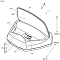
- the HUD device 1 comprises, as shown in Figs. 1 to 3 , a case body 10, a display unit 20, a circuit board 30, a reflection part 40, a combiner 50, a light guide body 60 formed integrally with the combiner 50, and a cover member 70.
- the HUD device 1 is configured as a stationary HUD device that is installed on a vehicle dashboard (e.g., above an instrument panel).
- a vehicle dashboard e.g., above an instrument panel.
- the components of the HUD device will be appropriately explained, assuming that as seen from an observer to see a display image displayed by the HUD device 1, an upward direction is "up”, a downward direction is “down”, a forward direction is “front”, and a backward direction is “back”, respectively (see the arrows at both ends of Fig. 1 and Fig. 3 ).
- the case body 10 comprises an upper case 11, a lower case 12, and a middle case 13.
- a first opening part 110 is formed in the upper case 11, a first opening part 110 is formed.
- a shape like a box with the upper side opened is formed by connecting the upper case 11 and lower case 12.
- the display unit 20, the circuit board 30, and the middle case 13 are housed.
- the upper case 11 has a mounting part (not shown) to mount the combiner 50, on the side ahead of the first opening part 110 thereof.
- a lower end part of the combiner 50 is fixed to the mounting part with a screw, for example. In this manner, the upper case 11 holds the combiner 50.
- the combiner 50 held by the upper case is shaped such as extended upward from the upper case 11.
- a second opening part 111 is formed for exposing the light guide body 60 forward and passing incident light (external light N1 described later) through the inside of the case body 10.
- the middle case 13 is placed on the lower case 12.
- a concave part 121 having a shape corresponding to the lower end portion of the reflection part 40 is formed.
- the reflection part 40 is held by the concave part 121 and a part (a rear inner surface) of the middle case 13. (For example, the reflection part 40 is held with one end inserted into the concave part 121 and a rear side surface fixed to the middle case 13 with adhesive tape or the like.)
- the middle case 13 is a substantially cylindrical member, and the display unit 20 is disposed on a part of the outside surface thereof (on the right side in Fig. 3 ).
- an emission port 130 that is a port to expose a display surface of the display unit 20 is formed.
- the middle case 13 may be provided with a transparent window member covering the emission port 130.
- the display unit 20 is configured to emit display light L representing a display image for notifying display information such as a vehicle speed and mileage, and comprises of a transmissive liquid crystal display comprising a liquid crystal panel and a backlight light source, or a self-luminous display, for example.
- the circuit board 30 is a printed circuit board formed by implementing a control unit (not shown) comprised of a microcomputer including a memory, such as a CPU and ROM, a graphic display controller (GDC) or the like on a place-shaped base material made of resin including a glass fiber or the like.
- the circuit board 30 is fixed to the lower case 12 by a not-shown fixing member, for example, and is located in front of the display unit 20 and between the upper case 11 and lower case 12.
- the circuit board 30 and display unit 20 are conductively connected via a flexible printed circuit (FPC) 3.
- One end of the FPC 3 is connected to the circuit board 30 via a connector C.
- the control unit acquires vehicle state information transmitted from an external device (not shown) such as a vehicle electronic control unit (ECU) via a communication line, and drives the display unit 20 according to the information (namely, displays a predetermined display image on the display unit 20).
- ECU vehicle electronice control unit
- an optical sensor 31 On the circuit board 30, an optical sensor 31, an amplifier circuit (not shown), a drive circuit (not shown) to drive the display unit 20 or the like are mounted.
- the optical sensor 31 is for detecting brightness of light reached, and disposed opposite to a facing surface 62 of the light guide body 60 described later, so that an optical axis of light incident to the optical sensor 31 is along the vertical direction (see Fig. 4 ).
- the optical sensor 31 supplies the amplifier circuit with a detection signal representing the brightness of light reached.
- the amplifier circuit amplifies the detection signal detected by the optical sensor 31, and supplies it to the control unit.
- the control unit adjusts the brightness of the display image displayed by the display unit 20 via the drive circuit based on the obtained detection signal. For example, when a value indicating the brightness of the light received by the optical sensor 31 is lower than a threshold value (previously stored), a background is assumed to be dark.
- the display brightness of the display unit 20 is increased by a predetermined degree. Specifically, for example, when the display unit 20 comprises a transmissive liquid crystal display, the brightness of the backlight light source is increased.
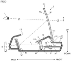
- the reflection part 40 is located on the display side of the display unit 20, that is, the exit side of the display light L, and reflects the reached display light L toward the combiner 50.
- the reflection part 40 is made of an aluminum deposited resin molded product, for example, and has a reflection surface configured as a curved surface for effectively reflecting the display light L from the display unit 20 to the combiner 50 (in Fig. 3 , the reflection surface is schematically shown as a plane). Further, as the reflection part 40 is held by the concave part 121 and a part of the middle case 13 as described before, the reflection surface is arranged so as to substantially facing the display side of the display unit 20.
- the display light L emitted by the display unit 20 reaches the reflection part through the emission port 130.
- the display light L reflected by the reflection part 40 is directed to the combiner 50 through the first opening part 110 of the upper case 11.
- the combiner 50 comprises a plate-shaped half-mirror having a curved surface, a hologram element, or the like. As described before, the combiner 50 is attached to the upper case 11, and a concave surface 50a thereof is substantially opposite to the reflection surface of the reflection part 40. As shown in Fig. 3 , the combiner 50 changes the optical path of the incident display light L after reflected by the reflection part 40 (changes the optical path of the display light L by reflection when a half-mirror is used as the combiner 50, and changes the optical path of the display light L by diffraction when a hologram element is used).
- the concave surface 50a of the combiner 50 has a function of condensing the display light L, and is configured as a curved surface capable of forming a virtual image far front (for example, about 1m ahead of the combiner 50) compared with the case of simply reflecting the light.
- the combiner 50 forms a virtual image of a display image at a front position F thereof, and passes the light from the front, whereby the HUD device 1 can allow an observer 2 to see both a virtual image and a real scene present in the front.
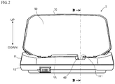
- the light guide body 60 is formed integrally with the combiner 50, and projected downward from a part of the lower end portion of the combiner 50, for example, as shown in Fig. 2 .
- the lower end UL of the combiner 50 is represented by a dotted line.
- the cross-section of the light guide body 60 is formed in a substantially triangular shape.
- the light guide body 60 is for guiding external light from a predetermined direction toward the optical sensor 31, and formed having a reflection surface 61 and a facing surface 62.
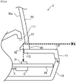
- the reflection surface 61 is an inclined surface on the rear side of the light guide body 60 (inclined by 45° with respect to the longitudinal direction, for example), and effectively reflects downward the external light N1 incident from the front to the light guide body 60 as shown in Fig. 4 (hereinafter, external light from the front is given a reference symbol "N1").
- Fig. 4 shows a magnified essential part of the HUD device 1 in the schematic cross-sectional view shown in Fig. 3 . In Fig. 4 , a hatching representing a cross section is omitted (same in Figs. 5 (a) and (b) according to a modification described later).
- the facing surface 62 is a lower surface of the light guide body 60, and is a surface opposite to the optical sensor 31 in the vertical direction.
- the facing surface 62 functions as an emission surface that emits the light guided downward by the light guide body 60 to the outside.
- a part of a front part 11F that is a part of the upper case 11 ahead of the combiner 50 serves as a cover part 112 covering a part of the facing surface 62 from the lower side.
- the upper case 11 is configured such that the cover part 112 covers only a part of the optical path of the external light N1 that is reflected by the reflection surface 61, emitted from the facing surface 62, and directed to the optical sensor 31.
- the cover member 70 is a member covering a side of the combiner 50, and made of a light-shielding resin material.
- the cover member 70 is provided for protecting a side of the combiner 50 (for example, protection from shock) and for preventing the incidence of external light to the combiner 50 (particularly, from the upper side surface located above the optical sensor 31).
- the cover member 70 is configured not to cover a part of the light guide body 60.
- the cover part 112 may be provided so as to block the optical path of the external light incident from the upper side of the combiner 50 (namely, the external light directed downward without being reflected by the reflection surface 61) without disturbing the optical path of the external light that is reflected by the reflection surface 61 and directed downward.
- the external light N1 from the front of the combiner 50 enters from the front side of the light guide body 60, and reflects on the reflection surface 61.
- the reflected external light N1 is guided to the inside of the light guide body 60, directed downward, and emitted from the facing surface 62.
- the external light N1 emitted from the facing surface 62 reaches the optical sensor 31 opposing the facing surface 62.
- the optical sensor 31 detects the brightness of the external light N1, and in response thereto, the control unit appropriately adjusts the brightness of the display unit 20 based on the detection result as described before.
- the cover member 70 is provided on the side of the combiner 50, external light does not enter from the side (particularly, the upper side of the upper part of the optical sensor 31).
- the external light N1 mainly from the front can be sensed.
- the front of the combiner 50 is a background direction for the observer 2 when watching a display image
- the brightness of the external light N1 can be regarded as the brightness of substantially background.
- a display image projecting direction namely, forward and background direction
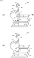
- a HUD device 101 according to a modification 1 is, as shown in Fig. 5 (a) , configured to detect not only external light N1 from the front, but also external light N2 from above (hereinafter, external light from above is denoted by a reference symbol "N2").
- a cover member 70 may not be provided, or at least a part of the cover member 70 located above an optical sensor 31 (the part near a B-B line in Fig. 2 ) May be cut out.
- a cover part 112 is provided so as not to disturb the optical path of the external light N2 incident from the upper side of a combiner 50.
- Such a configuration is useful when background brightness can be more reflected by detecting the external light N2 from above, in accordance with the vehicle interior environment.
- a HUD device 201 according to a modification 2 is, as shown in Fig. 5 (b) , configured to be able to detect external light N2 from above without detecting external light N1 from the front as much as possible.
- a cover member 70 may not be provided, or at least a part of the cover member 70 located above an optical sensor 31 may be cut out.
- a cover part 112 is provided so as not to disturb the optical path of the external light N2 incident from the upper side of a combiner 50.
- the reflection surface 61 as described above is not formed in a light guide body 260 according to the modification 2.
- Such a configuration is useful when the external light N2 from above is dominant to the background brightness due to any factor.
- the HUD device 1 (or 101, 201) explained above comprises a display unit 20 that emits display light L representing a display image; a combiner 50 that has a concave surface 50a to which the display light L emitted by the display unit 20 is incident, and concentrates the incident display light L so as to allow an observer 2 to see the display image from the concave surface 50a side superimposed on a background of the front; and an optical sensor 31 (an example of an optical detector) that is positioned below the combiner 50, and detects brightness of light reached, wherein the combiner 50 has a light guide body 60 that is integrated with the combiner 50 at a lower end part thereof, the light guide body 60 has a facing surface 62 that faces the optical sensor 31 in a vertical direction, guides external light from at least one of the front and above downward, of the external light incident, and emits the external light guided downward from the facing surface 62, and the optical sensor 31 detects brightness of the light emitted from the facing surface 62.
- the combiner 50 has a light guide
- the HUD device 1 (or 101, 201) has a simple structure. Further, as the number of parts can be decreased, the cost can be reduced.
- the light guide body 60 has a reflection surface 61 that reflects downward the external light N1 incident from the front, and emits the external light reflected by the reflection surface 61 from the facing surface 62.
- the reflection surface 61 that reflects downward the external light N1 incident from the front, and emits the external light reflected by the reflection surface 61 from the facing surface 62.
- the above description shows an example that the angle of the reflection surface 61 of the light guide body 60 is 45 degrees, but not limited thereto. It is possible to adjust (suppress) the amount of the external light N1 reaching the optical sensor 31 by displacing the reflection surface 61 from the tilt angle of 45 degrees.
- the above description shows an example that the display light L from the display unit 20 is reflected by the reflection part 40 and reached to the combiner 50, but not limited thereto.
- the HUD device may be configured such that the display unit emits the display light L directly to the combiner. In this case, the display unit and combiner are arranged so as to substantially opposite to each other, and the reflection part 40 is unnecessary.
- an automobile is taken as an example of vehicles to install the HUD device 1 (hereinafter, including the HUD devices 101 and 201), but not to be limited thereto.
- the HUD device 1 may be installed in the vicinity of a driver's seat in a ship, an airplane, or other vehicles. Further, the installation place is not limited to the vicinity of a driver's seat of a vehicle. It may also be applied to tabletop interiors or the like to be placed indoors.
- the HUD device 1 has been explained as a stationary type.
- the HUD device 1 may be configured integrally with a dashboard of a vehicle.
- a head-up display device for a vehicle has been explained as an example of application.
Description
- The present invention relates to a head-up display device.
- As a head-up display (HUD) device, for example, one disclosed in
Patent Literature 1 is known. This document describes a head-up display device comprising : a display unit configured to emit display light representing a display image; a combiner having a surface to which the display light emitted by the display unit enters, and to concentrate the incident display light to allow an observer to see the display image from the said surface side superimposed on a background of the front; and an optical detector configured to be positioned below the combiner, and detects brightness of light reached, wherein the combiner has a light guide body that is integrated with the combiner at a lower end part thereof, the light guide body has a facing surface that faces the optical detector in a vertical direction, guides external light from the front downward, of the external light incident, and emits the external light guided downward from the facing surface, and the optical detector detects brightness of the light emitted from the facing surface. - Patent Literature 1: Japanese Unexamined Patent Application Publication No.
H9-54276 JP H04 25816A transmission type hologram 2 is disposed in thewindshield 1. A glass block 5 as an emitting means is disposed in close contact with the inner surface of the passenger compartment of thewindshield 1 in a lower position appropriately spaced from the disposing position of thetransmission type hologram 2.JP H09 43531A GB 1322422 - The HUD device according to the
Patent Literature 1 requires exclusive parts (a prism 16, a reflector 17) for guiding light to be detected to an optical sensor as shown in Fig. 6 and Fig. 7 attached to the Document, and the configuration tends to be complex. - The present invention has been made in view of the above circumstances, and it is an object to provide a head-up display device that can detect background brightness with a simple configuration.
- In orderto achieve the above object, a head-up display device according to an aspect of the invention comprises:
- a display unit that emits display light representing a display image;
- a combiner that has a concave surface to which the display light emitted by the display unit is incident, and concentrates the incident display light to allow an observer to see the display image from the concave surface side superimposed on a background of the front; and
- an optical detector that is positioned below the combiner, and detects brightness of light reached,
- wherein the combiner has a light guide body that is integrated with the combiner at a lower end part thereof,
- the light guide body has a facing surface that faces the optical detector in a vertical direction, guides external light from at least one of the front and above downward, of the external light incident, and emits the external light guided downward from the facing surface, and
- the optical detector detects brightness of the light emitted from the facing surface.
- In the head-up display device, the light guide body may has a reflection surface that reflects downward the external light incident from the front, and may be configured to emit the external light reflected by the reflection surface from the facing surface.
- The head-up display device is provided with a cover part that covers a part of the facing surface from the lower side, and disturbs the optical path of the light that is passed through the light guide body from above the combiner, and directed downward.
- In the head-up display device, a light-shielding cover member that covers the upper side of the combiner may be provided, and may be configured to prevent incidence of external light from the upper side.
- The head-up display device may be provided with an adjustment means that adjusts the display brightness of the display unit based on the brightness of the light detected by the optical detector.
- According to the present invention, it is possible to provide a head-up display device capable of detecting background brightness with a simple configuration.
-
- [
Fig. 1] Fig. 1 is a perspective view of a HUD device according to an embodiment of the invention. - [
Fig. 2] Fig. 2 is a view of the HUD device as seen from the direction of the arrow A (from the front) shown inFig. 1 . - [
Fig. 3] Fig. 3 is a line B-B schematic cross-sectional view of the HUD device shown inFig. 2 . - [
Fig. 4] Fig. 4 is an enlarged view of an essential part of the HUD device shown inFig. 3 , primarily for explaining a function of a light guide body. - [
Fig. 5] Fig. 5 (a) is an enlarged view of an essential part of a HUD device according to amodification 1.Fig. 5 (b) is an enlarged view of an essential part of a HUD device according to amodification 2. - Hereinafter, a HUD device according to an embodiment of the present invention will be described with reference to the drawings.
- The
HUD device 1 comprises, as shown inFigs. 1 to 3 , acase body 10, adisplay unit 20, acircuit board 30, areflection part 40, acombiner 50, alight guide body 60 formed integrally with thecombiner 50, and acover member 70. - The
HUD device 1 is configured as a stationary HUD device that is installed on a vehicle dashboard (e.g., above an instrument panel). In the following description, the components of the HUD device will be appropriately explained, assuming that as seen from an observer to see a display image displayed by theHUD device 1, an upward direction is "up", a downward direction is "down", a forward direction is "front", and a backward direction is "back", respectively (see the arrows at both ends ofFig. 1 andFig. 3 ). - The
case body 10 comprises anupper case 11, alower case 12, and amiddle case 13. In theupper case 11, a firstopening part 110 is formed. A shape like a box with the upper side opened is formed by connecting theupper case 11 andlower case 12. In the box shape, thedisplay unit 20, thecircuit board 30, and themiddle case 13 are housed. - The
upper case 11 has a mounting part (not shown) to mount thecombiner 50, on the side ahead of the first openingpart 110 thereof. A lower end part of thecombiner 50 is fixed to the mounting part with a screw, for example. In this manner, theupper case 11 holds thecombiner 50. Thecombiner 50 held by the upper case is shaped such as extended upward from theupper case 11. - Further, in the
upper case 11, a second openingpart 111 is formed for exposing thelight guide body 60 forward and passing incident light (external light N1 described later) through the inside of thecase body 10. - The
middle case 13 is placed on thelower case 12. In thelower case 12, as shown inFig. 3 , aconcave part 121 having a shape corresponding to the lower end portion of thereflection part 40 is formed. Thereflection part 40 is held by theconcave part 121 and a part (a rear inner surface) of themiddle case 13. (For example, thereflection part 40 is held with one end inserted into theconcave part 121 and a rear side surface fixed to themiddle case 13 with adhesive tape or the like.) - The
middle case 13 is a substantially cylindrical member, and thedisplay unit 20 is disposed on a part of the outside surface thereof (on the right side inFig. 3 ). In themiddle case 13, anemission port 130 that is a port to expose a display surface of thedisplay unit 20 is formed. Themiddle case 13 may be provided with a transparent window member covering theemission port 130. - The
display unit 20 is configured to emit display light L representing a display image for notifying display information such as a vehicle speed and mileage, and comprises of a transmissive liquid crystal display comprising a liquid crystal panel and a backlight light source, or a self-luminous display, for example. - The
circuit board 30 is a printed circuit board formed by implementing a control unit (not shown) comprised of a microcomputer including a memory, such as a CPU and ROM, a graphic display controller (GDC) or the like on a place-shaped base material made of resin including a glass fiber or the like. Thecircuit board 30 is fixed to thelower case 12 by a not-shown fixing member, for example, and is located in front of thedisplay unit 20 and between theupper case 11 andlower case 12. Thecircuit board 30 anddisplay unit 20 are conductively connected via a flexible printed circuit (FPC) 3. One end of the FPC 3 is connected to thecircuit board 30 via a connector C. The control unit acquires vehicle state information transmitted from an external device (not shown) such as a vehicle electronic control unit (ECU) via a communication line, and drives thedisplay unit 20 according to the information (namely, displays a predetermined display image on the display unit 20). - On the
circuit board 30, anoptical sensor 31, an amplifier circuit (not shown), a drive circuit (not shown) to drive thedisplay unit 20 or the like are mounted. - The
optical sensor 31 is for detecting brightness of light reached, and disposed opposite to a facingsurface 62 of thelight guide body 60 described later, so that an optical axis of light incident to theoptical sensor 31 is along the vertical direction (seeFig. 4 ). Theoptical sensor 31 supplies the amplifier circuit with a detection signal representing the brightness of light reached.
The amplifier circuit amplifies the detection signal detected by theoptical sensor 31, and supplies it to the control unit. The control unit adjusts the brightness of the display image displayed by thedisplay unit 20 via the drive circuit based on the obtained detection signal. For example, when a value indicating the brightness of the light received by theoptical sensor 31 is lower than a threshold value (previously stored), a background is assumed to be dark. Thus, The display brightness of thedisplay unit 20 is increased by a predetermined degree. Specifically, for example, when thedisplay unit 20 comprises a transmissive liquid crystal display, the brightness of the backlight light source is increased. - The
reflection part 40 is located on the display side of thedisplay unit 20, that is, the exit side of the display light L, and reflects the reached display light L toward thecombiner 50. Thereflection part 40 is made of an aluminum deposited resin molded product, for example, and has a reflection surface configured as a curved surface for effectively reflecting the display light L from thedisplay unit 20 to the combiner 50 (inFig. 3 , the reflection surface is schematically shown as a plane). Further, as thereflection part 40 is held by theconcave part 121 and a part of themiddle case 13 as described before, the reflection surface is arranged so as to substantially facing the display side of thedisplay unit 20. The display light L emitted by thedisplay unit 20 reaches the reflection part through theemission port 130. The display light L reflected by thereflection part 40 is directed to thecombiner 50 through thefirst opening part 110 of theupper case 11. - The
combiner 50 comprises a plate-shaped half-mirror having a curved surface, a hologram element, or the like. As described before, thecombiner 50 is attached to theupper case 11, and aconcave surface 50a thereof is substantially opposite to the reflection surface of thereflection part 40. As shown inFig. 3 , thecombiner 50 changes the optical path of the incident display light L after reflected by the reflection part 40 (changes the optical path of the display light L by reflection when a half-mirror is used as thecombiner 50, and changes the optical path of the display light L by diffraction when a hologram element is used). Theconcave surface 50a of thecombiner 50 has a function of condensing the display light L, and is configured as a curved surface capable of forming a virtual image far front (for example, about 1m ahead of the combiner 50) compared with the case of simply reflecting the light. Thecombiner 50 forms a virtual image of a display image at a front position F thereof, and passes the light from the front, whereby theHUD device 1 can allow anobserver 2 to see both a virtual image and a real scene present in the front. - The
light guide body 60 is formed integrally with thecombiner 50, and projected downward from a part of the lower end portion of thecombiner 50, for example, as shown inFig. 2 . (For reference, inFig. 2 , the lower end UL of thecombiner 50 is represented by a dotted line.) As shown inFig. 3 , the cross-section of thelight guide body 60 is formed in a substantially triangular shape. - The
light guide body 60 is for guiding external light from a predetermined direction toward theoptical sensor 31, and formed having areflection surface 61 and a facingsurface 62. - The
reflection surface 61 is an inclined surface on the rear side of the light guide body 60 (inclined by 45° with respect to the longitudinal direction, for example), and effectively reflects downward the external light N1 incident from the front to thelight guide body 60 as shown inFig. 4 (hereinafter, external light from the front is given a reference symbol "N1").Fig. 4 shows a magnified essential part of theHUD device 1 in the schematic cross-sectional view shown inFig. 3 . InFig. 4 , a hatching representing a cross section is omitted (same inFigs. 5 (a) and (b) according to a modification described later). - The facing
surface 62 is a lower surface of thelight guide body 60, and is a surface opposite to theoptical sensor 31 in the vertical direction. The facingsurface 62 functions as an emission surface that emits the light guided downward by thelight guide body 60 to the outside. - A part of a
front part 11F that is a part of theupper case 11 ahead of thecombiner 50 serves as acover part 112 covering a part of the facingsurface 62 from the lower side. Theupper case 11 is configured such that thecover part 112 covers only a part of the optical path of the external light N1 that is reflected by thereflection surface 61, emitted from the facingsurface 62, and directed to theoptical sensor 31. - The
cover member 70 is a member covering a side of thecombiner 50, and made of a light-shielding resin material. Thecover member 70 is provided for protecting a side of the combiner 50 (for example, protection from shock) and for preventing the incidence of external light to the combiner 50 (particularly, from the upper side surface located above the optical sensor 31). Of course, as shown inFig. 2 , thecover member 70 is configured not to cover a part of thelight guide body 60. - It is also possible to prevent the light incident from the upper side of the
combiner 50 from reaching theoptical sensor 31 as much as possible by thecover part 112 without providing thecover member 70. For this purpose, thecover part 112 may be provided so as to block the optical path of the external light incident from the upper side of the combiner 50 (namely, the external light directed downward without being reflected by the reflection surface 61) without disturbing the optical path of the external light that is reflected by thereflection surface 61 and directed downward. - Now, how the external light N1 reaches the
optical sensor 31 will be explained by referring toFig. 4 . - The external light N1 from the front of the
combiner 50 enters from the front side of thelight guide body 60, and reflects on thereflection surface 61. The reflected external light N1 is guided to the inside of thelight guide body 60, directed downward, and emitted from the facingsurface 62. - The external light N1 emitted from the facing
surface 62 reaches theoptical sensor 31 opposing the facingsurface 62. Theoptical sensor 31 detects the brightness of the external light N1, and in response thereto, the control unit appropriately adjusts the brightness of thedisplay unit 20 based on the detection result as described before. - Particularly, in the embodiment, as the
cover member 70 is provided on the side of thecombiner 50, external light does not enter from the side (particularly, the upper side of the upper part of the optical sensor 31). Thus, the external light N1 mainly from the front can be sensed. In this manner, as the front of thecombiner 50 is a background direction for theobserver 2 when watching a display image, the brightness of the external light N1 can be regarded as the brightness of substantially background. Thus, for example, even when the vehicle interior is dark in the daytime in a tunnel near an exit and a display image projecting direction (namely, forward and background direction) is bright, it is possible to adjust the brightness of the projected image to appropriate brightness in accordance with the brightness in the projecting direction before the vehicle leaves the tunnel. - From here, a HUD device according to a modification will be explained by referring to
Figs. 5 (a) and (b) . Parts having similar functions as those of the embodiment will be denoted by the same reference numerals, and description overlapping with the embodiment will be omitted. - A
HUD device 101 according to amodification 1 is, as shown inFig. 5 (a) , configured to detect not only external light N1 from the front, but also external light N2 from above (hereinafter, external light from above is denoted by a reference symbol "N2"). - For detecting the external light N2 from above, a
cover member 70 may not be provided, or at least a part of thecover member 70 located above an optical sensor 31 (the part near a B-B line inFig. 2 ) May be cut out. Of course, in this case, acover part 112 is provided so as not to disturb the optical path of the external light N2 incident from the upper side of acombiner 50. - Such a configuration is useful when background brightness can be more reflected by detecting the external light N2 from above, in accordance with the vehicle interior environment.
- A
HUD device 201 according to amodification 2 is, as shown inFig. 5 (b) , configured to be able to detect external light N2 from above without detecting external light N1 from the front as much as possible. - In this case, similar to the modification1, a
cover member 70 may not be provided, or at least a part of thecover member 70 located above anoptical sensor 31 may be cut out. Acover part 112 is provided so as not to disturb the optical path of the external light N2 incident from the upper side of acombiner 50. To detect only the external light N2 from above, thereflection surface 61 as described above is not formed in alight guide body 260 according to themodification 2. - Such a configuration is useful when the external light N2 from above is dominant to the background brightness due to any factor.
- The HUD device 1 (or 101, 201) explained above comprises a
display unit 20 that emits display light L representing a display image;
acombiner 50 that has aconcave surface 50a to which the display light L emitted by thedisplay unit 20 is incident, and concentrates the incident display light L so as to allow anobserver 2 to see the display image from theconcave surface 50a side superimposed on a background of the front; and
an optical sensor 31 (an example of an optical detector) that is positioned below thecombiner 50, and detects brightness of light reached, wherein thecombiner 50 has alight guide body 60 that is integrated with thecombiner 50 at a lower end part thereof,
thelight guide body 60 has a facingsurface 62 that faces theoptical sensor 31 in a vertical direction, guides external light from at least one of the front and above downward, of the external light incident, and emits the external light guided downward from the facingsurface 62, and theoptical sensor 31 detects brightness of the light emitted from the facingsurface 62. - As described above, since the light guide body for guiding light to the optical sensor is configured integrally with the combiner, the HUD device 1 (or 101, 201) has a simple structure. Further, as the number of parts can be decreased, the cost can be reduced.
- Particularly, in the
HUD device 1 and theHUD device 101 according to themodification 1, thelight guide body 60 has areflection surface 61 that reflects downward the external light N1 incident from the front, and emits the external light reflected by thereflection surface 61 from the facingsurface 62. Thus, as described above, it is possible to effectively detect the brightness in the background direction. - The present invention is not to be limited to the aforementioned embodiment, modifications (
modifications 1 and 2), and drawings. It is of course possible to add various changes and modifications (including elimination of the constituent elements) to them. - The above description shows an example that the angle of the
reflection surface 61 of thelight guide body 60 is 45 degrees, but not limited thereto. It is possible to adjust (suppress) the amount of the external light N1 reaching theoptical sensor 31 by displacing thereflection surface 61 from the tilt angle of 45 degrees. - The above description shows an example that the display light L from the
display unit 20 is reflected by thereflection part 40 and reached to thecombiner 50, but not limited thereto. The HUD device may be configured such that the display unit emits the display light L directly to the combiner. In this case, the display unit and combiner are arranged so as to substantially opposite to each other, and thereflection part 40 is unnecessary. - In the above description, an automobile is taken as an example of vehicles to install the HUD device 1 (hereinafter, including the
HUD devices 101 and 201), but not to be limited thereto. TheHUD device 1 may be installed in the vicinity of a driver's seat in a ship, an airplane, or other vehicles. Further, the installation place is not limited to the vicinity of a driver's seat of a vehicle. It may also be applied to tabletop interiors or the like to be placed indoors. - In the above description, the
HUD device 1 has been explained as a stationary type. However, for example, theHUD device 1 may be configured integrally with a dashboard of a vehicle. - In the above description, unimportant known techniques are appropriately omitted to facilitate understanding of the present invention.
- In the aforementioned embodiment, a head-up display device for a vehicle has been explained as an example of application. However, it is possible to apply the invention to a ship or special vehicles such as agricultural machinery and construction equipment.
-
- 1 HUD device
- 2 Observer
- 10 Case body
- 11 Upper case
- 11F Front part
- 110 First opening part
- 111 Second opening part
- 112 Cover part
- 12 Lower case
- 121 Concave part
- 13 Middle case
- 130 Emission port
- 20 Display unit
- 30 Circuit board
- 31 Optical sensor
- 40 Reflection part
- 50 Combiner
- 50a Concave surface
- 60 Reflection surface
- 62 facing surfaces
- 70 Cover member
Claims (4)
- A head-up display device comprising:a display unit (20) configured to emit display light (L) representing a display image;a combiner (50) having a concave surface (50a) to which the display light emitted by the display unit enters, and to concentrate the incident display light to allow an observer (2) to see the display image from the concave surface (50a) side superimposed on a background of the front; andan optical detector (31) configured to be positioned below the combiner, and detects brightness of light reached,wherein the combiner has a light guide body (60) that is integrated with the combiner at a lower end part thereof,the light guide body has a facing surface (62) that faces the optical detector in a vertical direction, guides external light from at least one of the front and above downward, of the external light incident, and emits the external light guided downward from the facing surface, andthe optical detector detects brightness of the light emitted from the facing surface, anda cover part (112) that covers a part of the facing surface from the lower side, and disturbs the optical path of the light that is passed through the light guide body from above the combiner, and directed downward.
- The head-up display device according to claim 1, wherein
the light guide body has a reflection surface (61) that reflects downward the external light incident from the front, and is configured to emit the external light reflected by the reflection surface from the facing surface. - The head-up display device according to claim 1 or 2, further comprising a light-shielding cover member (70) that covers the upper side of the combiner, and is configured to prevent incidence of external light from the upper side.
- The head-up display device according to one of claims 1 to 3, further comprising an adjustment means that adjusts the display brightness of the display unit based on the brightness of the light detected by the optical detector.
Applications Claiming Priority (2)
| Application Number | Priority Date | Filing Date | Title |
|---|---|---|---|
| JP2012078120A JP5998578B2 (en) | 2012-03-29 | 2012-03-29 | Head-up display device |
| PCT/JP2013/056261 WO2013146160A1 (en) | 2012-03-29 | 2013-03-07 | Heads-up display device |
Publications (3)
| Publication Number | Publication Date |
|---|---|
| EP2833194A1 EP2833194A1 (en) | 2015-02-04 |
| EP2833194A4 EP2833194A4 (en) | 2017-04-12 |
| EP2833194B1 true EP2833194B1 (en) | 2018-06-06 |
Family
ID=49259428
Family Applications (1)
| Application Number | Title | Priority Date | Filing Date |
|---|---|---|---|
| EP13768908.9A Not-in-force EP2833194B1 (en) | 2012-03-29 | 2013-03-07 | Heads-up display device |
Country Status (7)
| Country | Link |
|---|---|
| US (1) | US9242604B2 (en) |
| EP (1) | EP2833194B1 (en) |
| JP (1) | JP5998578B2 (en) |
| KR (1) | KR20140141629A (en) |
| CN (1) | CN104204903B (en) |
| IN (1) | IN2014DN08234A (en) |
| WO (1) | WO2013146160A1 (en) |
Families Citing this family (33)
| Publication number | Priority date | Publication date | Assignee | Title |
|---|---|---|---|---|
| JP6349632B2 (en) * | 2013-06-24 | 2018-07-04 | 日本精機株式会社 | Head-up display device |
| JP5957710B2 (en) * | 2013-12-27 | 2016-07-27 | パナソニックIpマネジメント株式会社 | Display device and display unit |
| JP2015127170A (en) * | 2013-12-27 | 2015-07-09 | パイオニア株式会社 | Head-up display, control method, program, and memory medium |
| CN104914574B (en) * | 2014-03-11 | 2018-12-14 | 鸿富锦精密工业(深圳)有限公司 | Head-up display device |
| CN103885183B (en) * | 2014-03-12 | 2017-01-04 | 惠州市华阳多媒体电子有限公司 | Callable vehicle-mounted head-up display and vehicle |
| EP2930048A1 (en) * | 2014-04-10 | 2015-10-14 | Johnson Controls Automotive Electronics SAS | Head up display projecting visual information onto a screen |
| JP2015214246A (en) * | 2014-05-09 | 2015-12-03 | カルソニックカンセイ株式会社 | Vehicle display device |
| JP6284153B2 (en) * | 2014-06-12 | 2018-02-28 | 矢崎総業株式会社 | External light introducing member and vehicle display device |
| DE112015002757B4 (en) | 2014-06-12 | 2021-07-29 | Yazaki Corporation | Visor body and vehicle display device |
| EP3165959B1 (en) * | 2014-07-01 | 2018-11-07 | Ricoh Company, Ltd. | Vehicular display device with improved brightness adjustment regarding to the background illuminance |
| DE102014019160B4 (en) * | 2014-12-19 | 2021-04-29 | Audi Ag | Method for reducing a reflection when operating a head-up display of a motor vehicle, a head-up display, and a motor vehicle with a head-up display |
| TWI572503B (en) * | 2015-02-24 | 2017-03-01 | 晶典有限公司 | Head up display system |
| TWI554785B (en) * | 2015-03-19 | 2016-10-21 | 尚立光電股份有限公司 | Displayer with asymmetry prism and head up displayer thereof |
| DE102016209526A1 (en) * | 2015-06-12 | 2016-12-15 | Ford Global Technologies, Llc | A projection device and method for projecting a virtual image into a field of view of a driver of a vehicle |
| JP6595250B2 (en) * | 2015-08-06 | 2019-10-23 | 株式会社ポラテクノ | Head-up display device |
| JP6661955B2 (en) * | 2015-10-08 | 2020-03-11 | 株式会社リコー | Display device |
| KR102363992B1 (en) * | 2015-11-24 | 2022-02-18 | 현대모비스 주식회사 | Head up display device for vehicle |
| US20170148216A1 (en) * | 2015-11-25 | 2017-05-25 | Continental Automotive Systems, Inc. | Display system adjustable based on background |
| EP4043944A1 (en) * | 2016-01-12 | 2022-08-17 | Magic Leap, Inc. | Beam angle sensor in virtual/augmented reality system |
| WO2017147158A1 (en) * | 2016-02-22 | 2017-08-31 | Navdy, Inc. | Head-up display device and method for constructing the same |
| FR3050542B1 (en) * | 2016-04-26 | 2019-07-12 | Valeo Comfort And Driving Assistance | DISPLAY COMPRISING A LIGHT SENSOR |
| FR3050541B1 (en) * | 2016-04-26 | 2019-07-12 | Valeo Comfort And Driving Assistance | DISPLAY |
| JP6559105B2 (en) * | 2016-08-31 | 2019-08-14 | 富士フイルム株式会社 | Head-up display device |
| CN106547094A (en) * | 2016-11-25 | 2017-03-29 | 刘涛 | The equipment that new line shows is realized using shield glass |
| CN106772967A (en) * | 2016-12-06 | 2017-05-31 | 中国航空工业集团公司洛阳电光设备研究所 | A kind of Clairvoyant type speech display optical system |
| CN108237975B (en) * | 2016-12-23 | 2021-06-11 | 大众汽车(中国)投资有限公司 | Method and device for illumination adjustment |
| KR20180093583A (en) * | 2017-02-14 | 2018-08-22 | 현대모비스 주식회사 | Head up display apparatus having multi display field capable of individual control and display control method for head up dispaly apparatus |
| US20190033582A1 (en) * | 2017-07-31 | 2019-01-31 | Benoit CHAUVEAU | Embedded sensor in a heads-up display (hud) panel |
| USD888633S1 (en) * | 2017-10-17 | 2020-06-30 | Lg Electronics Inc. | Head-up display for car |
| USD900689S1 (en) * | 2017-10-17 | 2020-11-03 | Lg Electronics Inc. | Head-up display for car |
| JP6995646B2 (en) * | 2018-01-26 | 2022-01-14 | 本田技研工業株式会社 | Display device |
| FR3084476B1 (en) * | 2018-07-30 | 2022-12-30 | Valeo Comfort & Driving Assistance | LIGHT SENSOR DISPLAY |
| CN109521564A (en) * | 2018-11-20 | 2019-03-26 | 惠州市华阳多媒体电子有限公司 | A kind of vehicle-mounted multi-screen holographic projection system |
Family Cites Families (9)
| Publication number | Priority date | Publication date | Assignee | Title |
|---|---|---|---|---|
| CA954347A (en) * | 1970-06-22 | 1974-09-10 | Robert K. Kirschner | Head-up display |
| JPH0425816A (en) * | 1990-05-22 | 1992-01-29 | Nissan Motor Co Ltd | Foreground brightness detection device |
| JP3241824B2 (en) * | 1992-10-30 | 2001-12-25 | カルソニックカンセイ株式会社 | Head-up display device with automatic dimming function for vehicles |
| JPH0943531A (en) * | 1995-07-31 | 1997-02-14 | Fujitsu Ltd | Display device for vehicle |
| JPH0954276A (en) * | 1995-08-11 | 1997-02-25 | Denso Corp | Head-up display |
| JP4089075B2 (en) * | 1999-03-30 | 2008-05-21 | 株式会社島津製作所 | Head-up display system |
| US7561966B2 (en) * | 2003-12-17 | 2009-07-14 | Denso Corporation | Vehicle information display system |
| JP5012640B2 (en) * | 2008-04-25 | 2012-08-29 | 株式会社島津製作所 | Display device |
| DE102009053825A1 (en) * | 2009-11-18 | 2011-05-19 | Trw Automotive Electronics & Components Gmbh | Optical sensor device for detecting ambient light |
-
2012
- 2012-03-29 JP JP2012078120A patent/JP5998578B2/en not_active Expired - Fee Related
-
2013
- 2013-03-07 WO PCT/JP2013/056261 patent/WO2013146160A1/en active Application Filing
- 2013-03-07 KR KR1020147027744A patent/KR20140141629A/en not_active Application Discontinuation
- 2013-03-07 US US14/388,737 patent/US9242604B2/en not_active Expired - Fee Related
- 2013-03-07 IN IN8234DEN2014 patent/IN2014DN08234A/en unknown
- 2013-03-07 CN CN201380016253.1A patent/CN104204903B/en not_active Expired - Fee Related
- 2013-03-07 EP EP13768908.9A patent/EP2833194B1/en not_active Not-in-force
Non-Patent Citations (1)
| Title |
|---|
| None * |
Also Published As
| Publication number | Publication date |
|---|---|
| KR20140141629A (en) | 2014-12-10 |
| US20150035725A1 (en) | 2015-02-05 |
| EP2833194A1 (en) | 2015-02-04 |
| JP5998578B2 (en) | 2016-09-28 |
| CN104204903A (en) | 2014-12-10 |
| CN104204903B (en) | 2016-08-31 |
| JP2013205817A (en) | 2013-10-07 |
| WO2013146160A1 (en) | 2013-10-03 |
| EP2833194A4 (en) | 2017-04-12 |
| US9242604B2 (en) | 2016-01-26 |
| IN2014DN08234A (en) | 2015-05-15 |
Similar Documents
| Publication | Publication Date | Title |
|---|---|---|
| EP2833194B1 (en) | Heads-up display device | |
| US20160178900A1 (en) | Head-up display device | |
| EP3057305B1 (en) | Vehicle front camera module integrated with rearview mirror | |
| US4978214A (en) | Display apparatus for automotive vehicle | |
| US9360183B2 (en) | Mirror apparatus for a vehicle | |
| EP3457194A1 (en) | Head-up display device | |
| JP7008267B2 (en) | Head-up display device | |
| CN111703303A (en) | Display device | |
| US10634908B2 (en) | Display device and display device main body including first and second emitting portions | |
| US11330691B2 (en) | Display comprising a light sensor | |
| CN109863056B (en) | Head-up display device | |
| US9244276B2 (en) | Head-up display device | |
| KR102436578B1 (en) | Display unit for vehicle and controlling method thereof | |
| US20150293368A1 (en) | Dashboard, and optical system for automobile | |
| JP4622606B2 (en) | Solar radiation detection device and vehicle instrument system | |
| CN105774652B (en) | Display device for outputting optical markings and method for producing such a display device | |
| CN110857070B (en) | External sensor | |
| JP7136127B2 (en) | vehicle display | |
| US11175496B2 (en) | Display | |
| KR20230089459A (en) | Head up display apparatus | |
| CN113302077A (en) | Head-up display device | |
| US20190033582A1 (en) | Embedded sensor in a heads-up display (hud) panel | |
| JP2005035415A (en) | Display device for vehicle | |
| KR20130107933A (en) | Sensing module and control device of rear view mirror in a vehicle using the same | |
| KR20130107935A (en) | Sensing module and control device of rear view mirror in a vehicle using the same |
Legal Events
| Date | Code | Title | Description |
|---|---|---|---|
| PUAI | Public reference made under article 153(3) epc to a published international application that has entered the european phase |
Free format text: ORIGINAL CODE: 0009012 |
|
| 17P | Request for examination filed |
Effective date: 20141022 |
|
| AK | Designated contracting states |
Kind code of ref document: A1 Designated state(s): AL AT BE BG CH CY CZ DE DK EE ES FI FR GB GR HR HU IE IS IT LI LT LU LV MC MK MT NL NO PL PT RO RS SE SI SK SM TR |
|
| AX | Request for extension of the european patent |
Extension state: BA ME |
|
| DAX | Request for extension of the european patent (deleted) | ||
| RA4 | Supplementary search report drawn up and despatched (corrected) |
Effective date: 20170314 |
|
| RIC1 | Information provided on ipc code assigned before grant |
Ipc: G02F 1/1335 20060101ALN20170308BHEP Ipc: G02B 27/01 20060101AFI20170308BHEP Ipc: G09G 3/34 20060101ALI20170308BHEP Ipc: B60K 35/00 20060101ALI20170308BHEP |
|
| RIC1 | Information provided on ipc code assigned before grant |
Ipc: G09G 3/34 20060101ALI20171222BHEP Ipc: G02B 27/01 20060101AFI20171222BHEP Ipc: B60K 35/00 20060101ALI20171222BHEP Ipc: G02F 1/1335 20060101ALN20171222BHEP |
|
| GRAP | Despatch of communication of intention to grant a patent |
Free format text: ORIGINAL CODE: EPIDOSNIGR1 |
|
| STAA | Information on the status of an ep patent application or granted ep patent |
Free format text: STATUS: GRANT OF PATENT IS INTENDED |
|
| INTG | Intention to grant announced |
Effective date: 20180209 |
|
| GRAS | Grant fee paid |
Free format text: ORIGINAL CODE: EPIDOSNIGR3 |
|
| GRAA | (expected) grant |
Free format text: ORIGINAL CODE: 0009210 |
|
| STAA | Information on the status of an ep patent application or granted ep patent |
Free format text: STATUS: THE PATENT HAS BEEN GRANTED |
|
| AK | Designated contracting states |
Kind code of ref document: B1 Designated state(s): AL AT BE BG CH CY CZ DE DK EE ES FI FR GB GR HR HU IE IS IT LI LT LU LV MC MK MT NL NO PL PT RO RS SE SI SK SM TR |
|
| REG | Reference to a national code |
Ref country code: GB Ref legal event code: FG4D |
|
| REG | Reference to a national code |
Ref country code: CH Ref legal event code: EP Ref country code: AT Ref legal event code: REF Ref document number: 1006738 Country of ref document: AT Kind code of ref document: T Effective date: 20180615 |
|
| REG | Reference to a national code |
Ref country code: IE Ref legal event code: FG4D |
|
| REG | Reference to a national code |
Ref country code: DE Ref legal event code: R096 Ref document number: 602013038591 Country of ref document: DE |
|
| REG | Reference to a national code |
Ref country code: NL Ref legal event code: MP Effective date: 20180606 |
|
| REG | Reference to a national code |
Ref country code: LT Ref legal event code: MG4D |
|
| PG25 | Lapsed in a contracting state [announced via postgrant information from national office to epo] |
Ref country code: FI Free format text: LAPSE BECAUSE OF FAILURE TO SUBMIT A TRANSLATION OF THE DESCRIPTION OR TO PAY THE FEE WITHIN THE PRESCRIBED TIME-LIMIT Effective date: 20180606 Ref country code: BG Free format text: LAPSE BECAUSE OF FAILURE TO SUBMIT A TRANSLATION OF THE DESCRIPTION OR TO PAY THE FEE WITHIN THE PRESCRIBED TIME-LIMIT Effective date: 20180906 Ref country code: LT Free format text: LAPSE BECAUSE OF FAILURE TO SUBMIT A TRANSLATION OF THE DESCRIPTION OR TO PAY THE FEE WITHIN THE PRESCRIBED TIME-LIMIT Effective date: 20180606 Ref country code: SE Free format text: LAPSE BECAUSE OF FAILURE TO SUBMIT A TRANSLATION OF THE DESCRIPTION OR TO PAY THE FEE WITHIN THE PRESCRIBED TIME-LIMIT Effective date: 20180606 Ref country code: NO Free format text: LAPSE BECAUSE OF FAILURE TO SUBMIT A TRANSLATION OF THE DESCRIPTION OR TO PAY THE FEE WITHIN THE PRESCRIBED TIME-LIMIT Effective date: 20180906 Ref country code: ES Free format text: LAPSE BECAUSE OF FAILURE TO SUBMIT A TRANSLATION OF THE DESCRIPTION OR TO PAY THE FEE WITHIN THE PRESCRIBED TIME-LIMIT Effective date: 20180606 Ref country code: CY Free format text: LAPSE BECAUSE OF FAILURE TO SUBMIT A TRANSLATION OF THE DESCRIPTION OR TO PAY THE FEE WITHIN THE PRESCRIBED TIME-LIMIT Effective date: 20180606 |
|
| PG25 | Lapsed in a contracting state [announced via postgrant information from national office to epo] |
Ref country code: GR Free format text: LAPSE BECAUSE OF FAILURE TO SUBMIT A TRANSLATION OF THE DESCRIPTION OR TO PAY THE FEE WITHIN THE PRESCRIBED TIME-LIMIT Effective date: 20180907 Ref country code: HR Free format text: LAPSE BECAUSE OF FAILURE TO SUBMIT A TRANSLATION OF THE DESCRIPTION OR TO PAY THE FEE WITHIN THE PRESCRIBED TIME-LIMIT Effective date: 20180606 Ref country code: RS Free format text: LAPSE BECAUSE OF FAILURE TO SUBMIT A TRANSLATION OF THE DESCRIPTION OR TO PAY THE FEE WITHIN THE PRESCRIBED TIME-LIMIT Effective date: 20180606 Ref country code: LV Free format text: LAPSE BECAUSE OF FAILURE TO SUBMIT A TRANSLATION OF THE DESCRIPTION OR TO PAY THE FEE WITHIN THE PRESCRIBED TIME-LIMIT Effective date: 20180606 |
|
| REG | Reference to a national code |
Ref country code: AT Ref legal event code: MK05 Ref document number: 1006738 Country of ref document: AT Kind code of ref document: T Effective date: 20180606 |
|
| PG25 | Lapsed in a contracting state [announced via postgrant information from national office to epo] |
Ref country code: NL Free format text: LAPSE BECAUSE OF FAILURE TO SUBMIT A TRANSLATION OF THE DESCRIPTION OR TO PAY THE FEE WITHIN THE PRESCRIBED TIME-LIMIT Effective date: 20180606 |
|
| PG25 | Lapsed in a contracting state [announced via postgrant information from national office to epo] |
Ref country code: AT Free format text: LAPSE BECAUSE OF FAILURE TO SUBMIT A TRANSLATION OF THE DESCRIPTION OR TO PAY THE FEE WITHIN THE PRESCRIBED TIME-LIMIT Effective date: 20180606 Ref country code: EE Free format text: LAPSE BECAUSE OF FAILURE TO SUBMIT A TRANSLATION OF THE DESCRIPTION OR TO PAY THE FEE WITHIN THE PRESCRIBED TIME-LIMIT Effective date: 20180606 Ref country code: IS Free format text: LAPSE BECAUSE OF FAILURE TO SUBMIT A TRANSLATION OF THE DESCRIPTION OR TO PAY THE FEE WITHIN THE PRESCRIBED TIME-LIMIT Effective date: 20181006 Ref country code: CZ Free format text: LAPSE BECAUSE OF FAILURE TO SUBMIT A TRANSLATION OF THE DESCRIPTION OR TO PAY THE FEE WITHIN THE PRESCRIBED TIME-LIMIT Effective date: 20180606 Ref country code: SK Free format text: LAPSE BECAUSE OF FAILURE TO SUBMIT A TRANSLATION OF THE DESCRIPTION OR TO PAY THE FEE WITHIN THE PRESCRIBED TIME-LIMIT Effective date: 20180606 Ref country code: RO Free format text: LAPSE BECAUSE OF FAILURE TO SUBMIT A TRANSLATION OF THE DESCRIPTION OR TO PAY THE FEE WITHIN THE PRESCRIBED TIME-LIMIT Effective date: 20180606 Ref country code: PL Free format text: LAPSE BECAUSE OF FAILURE TO SUBMIT A TRANSLATION OF THE DESCRIPTION OR TO PAY THE FEE WITHIN THE PRESCRIBED TIME-LIMIT Effective date: 20180606 |
|
| PG25 | Lapsed in a contracting state [announced via postgrant information from national office to epo] |
Ref country code: SM Free format text: LAPSE BECAUSE OF FAILURE TO SUBMIT A TRANSLATION OF THE DESCRIPTION OR TO PAY THE FEE WITHIN THE PRESCRIBED TIME-LIMIT Effective date: 20180606 Ref country code: IT Free format text: LAPSE BECAUSE OF FAILURE TO SUBMIT A TRANSLATION OF THE DESCRIPTION OR TO PAY THE FEE WITHIN THE PRESCRIBED TIME-LIMIT Effective date: 20180606 |
|
| REG | Reference to a national code |
Ref country code: DE Ref legal event code: R097 Ref document number: 602013038591 Country of ref document: DE |
|
| PLBE | No opposition filed within time limit |
Free format text: ORIGINAL CODE: 0009261 |
|
| STAA | Information on the status of an ep patent application or granted ep patent |
Free format text: STATUS: NO OPPOSITION FILED WITHIN TIME LIMIT |
|
| 26N | No opposition filed |
Effective date: 20190307 |
|
| PG25 | Lapsed in a contracting state [announced via postgrant information from national office to epo] |
Ref country code: SI Free format text: LAPSE BECAUSE OF FAILURE TO SUBMIT A TRANSLATION OF THE DESCRIPTION OR TO PAY THE FEE WITHIN THE PRESCRIBED TIME-LIMIT Effective date: 20180606 Ref country code: DK Free format text: LAPSE BECAUSE OF FAILURE TO SUBMIT A TRANSLATION OF THE DESCRIPTION OR TO PAY THE FEE WITHIN THE PRESCRIBED TIME-LIMIT Effective date: 20180606 |
|
| REG | Reference to a national code |
Ref country code: DE Ref legal event code: R119 Ref document number: 602013038591 Country of ref document: DE |
|
| PG25 | Lapsed in a contracting state [announced via postgrant information from national office to epo] |
Ref country code: MC Free format text: LAPSE BECAUSE OF FAILURE TO SUBMIT A TRANSLATION OF THE DESCRIPTION OR TO PAY THE FEE WITHIN THE PRESCRIBED TIME-LIMIT Effective date: 20180606 |
|
| REG | Reference to a national code |
Ref country code: CH Ref legal event code: PL |
|
| GBPC | Gb: european patent ceased through non-payment of renewal fee |
Effective date: 20190307 |
|
| PG25 | Lapsed in a contracting state [announced via postgrant information from national office to epo] |
Ref country code: LU Free format text: LAPSE BECAUSE OF NON-PAYMENT OF DUE FEES Effective date: 20190307 Ref country code: AL Free format text: LAPSE BECAUSE OF FAILURE TO SUBMIT A TRANSLATION OF THE DESCRIPTION OR TO PAY THE FEE WITHIN THE PRESCRIBED TIME-LIMIT Effective date: 20180606 |
|
| REG | Reference to a national code |
Ref country code: BE Ref legal event code: MM Effective date: 20190331 |
|
| PG25 | Lapsed in a contracting state [announced via postgrant information from national office to epo] |
Ref country code: LI Free format text: LAPSE BECAUSE OF NON-PAYMENT OF DUE FEES Effective date: 20190331 Ref country code: GB Free format text: LAPSE BECAUSE OF NON-PAYMENT OF DUE FEES Effective date: 20190307 Ref country code: DE Free format text: LAPSE BECAUSE OF NON-PAYMENT OF DUE FEES Effective date: 20191001 Ref country code: CH Free format text: LAPSE BECAUSE OF NON-PAYMENT OF DUE FEES Effective date: 20190331 Ref country code: IE Free format text: LAPSE BECAUSE OF NON-PAYMENT OF DUE FEES Effective date: 20190307 |
|
| PG25 | Lapsed in a contracting state [announced via postgrant information from national office to epo] |
Ref country code: BE Free format text: LAPSE BECAUSE OF NON-PAYMENT OF DUE FEES Effective date: 20190331 Ref country code: FR Free format text: LAPSE BECAUSE OF NON-PAYMENT OF DUE FEES Effective date: 20190331 |
|
| PG25 | Lapsed in a contracting state [announced via postgrant information from national office to epo] |
Ref country code: TR Free format text: LAPSE BECAUSE OF FAILURE TO SUBMIT A TRANSLATION OF THE DESCRIPTION OR TO PAY THE FEE WITHIN THE PRESCRIBED TIME-LIMIT Effective date: 20180606 |
|
| PG25 | Lapsed in a contracting state [announced via postgrant information from national office to epo] |
Ref country code: MT Free format text: LAPSE BECAUSE OF NON-PAYMENT OF DUE FEES Effective date: 20190307 Ref country code: PT Free format text: LAPSE BECAUSE OF FAILURE TO SUBMIT A TRANSLATION OF THE DESCRIPTION OR TO PAY THE FEE WITHIN THE PRESCRIBED TIME-LIMIT Effective date: 20181008 |
|
| PG25 | Lapsed in a contracting state [announced via postgrant information from national office to epo] |
Ref country code: HU Free format text: LAPSE BECAUSE OF FAILURE TO SUBMIT A TRANSLATION OF THE DESCRIPTION OR TO PAY THE FEE WITHIN THE PRESCRIBED TIME-LIMIT; INVALID AB INITIO Effective date: 20130307 |
|
| PG25 | Lapsed in a contracting state [announced via postgrant information from national office to epo] |
Ref country code: MK Free format text: LAPSE BECAUSE OF FAILURE TO SUBMIT A TRANSLATION OF THE DESCRIPTION OR TO PAY THE FEE WITHIN THE PRESCRIBED TIME-LIMIT Effective date: 20180606 |