EP2833011A1 - Railway axlebox assembly and railway axlebox including the same - Google Patents
Railway axlebox assembly and railway axlebox including the same Download PDFInfo
- Publication number
- EP2833011A1 EP2833011A1 EP13306107.7A EP13306107A EP2833011A1 EP 2833011 A1 EP2833011 A1 EP 2833011A1 EP 13306107 A EP13306107 A EP 13306107A EP 2833011 A1 EP2833011 A1 EP 2833011A1
- Authority
- EP
- European Patent Office
- Prior art keywords
- sealing
- ring
- railway axlebox
- railway
- assembly according
- Prior art date
- Legal status (The legal status is an assumption and is not a legal conclusion. Google has not performed a legal analysis and makes no representation as to the accuracy of the status listed.)
- Withdrawn
Links
Images

Classifications
-
- B—PERFORMING OPERATIONS; TRANSPORTING
- B61—RAILWAYS
- B61F—RAIL VEHICLE SUSPENSIONS, e.g. UNDERFRAMES, BOGIES OR ARRANGEMENTS OF WHEEL AXLES; RAIL VEHICLES FOR USE ON TRACKS OF DIFFERENT WIDTH; PREVENTING DERAILING OF RAIL VEHICLES; WHEEL GUARDS, OBSTRUCTION REMOVERS OR THE LIKE FOR RAIL VEHICLES
- B61F15/00—Axle-boxes
- B61F15/20—Details
- B61F15/22—Sealing means preventing entrance of dust or leakage of oil
-
- B—PERFORMING OPERATIONS; TRANSPORTING
- B61—RAILWAYS
- B61F—RAIL VEHICLE SUSPENSIONS, e.g. UNDERFRAMES, BOGIES OR ARRANGEMENTS OF WHEEL AXLES; RAIL VEHICLES FOR USE ON TRACKS OF DIFFERENT WIDTH; PREVENTING DERAILING OF RAIL VEHICLES; WHEEL GUARDS, OBSTRUCTION REMOVERS OR THE LIKE FOR RAIL VEHICLES
- B61F15/00—Axle-boxes
- B61F15/20—Details
-
- B—PERFORMING OPERATIONS; TRANSPORTING
- B61—RAILWAYS
- B61F—RAIL VEHICLE SUSPENSIONS, e.g. UNDERFRAMES, BOGIES OR ARRANGEMENTS OF WHEEL AXLES; RAIL VEHICLES FOR USE ON TRACKS OF DIFFERENT WIDTH; PREVENTING DERAILING OF RAIL VEHICLES; WHEEL GUARDS, OBSTRUCTION REMOVERS OR THE LIKE FOR RAIL VEHICLES
- B61F15/00—Axle-boxes
- B61F15/02—Axle-boxes with journal bearings
-
- F—MECHANICAL ENGINEERING; LIGHTING; HEATING; WEAPONS; BLASTING
- F16—ENGINEERING ELEMENTS AND UNITS; GENERAL MEASURES FOR PRODUCING AND MAINTAINING EFFECTIVE FUNCTIONING OF MACHINES OR INSTALLATIONS; THERMAL INSULATION IN GENERAL
- F16C—SHAFTS; FLEXIBLE SHAFTS; ELEMENTS OR CRANKSHAFT MECHANISMS; ROTARY BODIES OTHER THAN GEARING ELEMENTS; BEARINGS
- F16C33/00—Parts of bearings; Special methods for making bearings or parts thereof
- F16C33/72—Sealings
- F16C33/76—Sealings of ball or roller bearings
- F16C33/78—Sealings of ball or roller bearings with a diaphragm, disc, or ring, with or without resilient members
- F16C33/7816—Details of the sealing or parts thereof, e.g. geometry, material
- F16C33/782—Details of the sealing or parts thereof, e.g. geometry, material of the sealing region
- F16C33/7826—Details of the sealing or parts thereof, e.g. geometry, material of the sealing region of the opposing surface cooperating with the seal, e.g. a shoulder surface of a bearing ring
-
- F—MECHANICAL ENGINEERING; LIGHTING; HEATING; WEAPONS; BLASTING
- F16—ENGINEERING ELEMENTS AND UNITS; GENERAL MEASURES FOR PRODUCING AND MAINTAINING EFFECTIVE FUNCTIONING OF MACHINES OR INSTALLATIONS; THERMAL INSULATION IN GENERAL
- F16C—SHAFTS; FLEXIBLE SHAFTS; ELEMENTS OR CRANKSHAFT MECHANISMS; ROTARY BODIES OTHER THAN GEARING ELEMENTS; BEARINGS
- F16C33/00—Parts of bearings; Special methods for making bearings or parts thereof
- F16C33/72—Sealings
- F16C33/76—Sealings of ball or roller bearings
- F16C33/78—Sealings of ball or roller bearings with a diaphragm, disc, or ring, with or without resilient members
- F16C33/7886—Sealings of ball or roller bearings with a diaphragm, disc, or ring, with or without resilient members mounted outside the gap between the inner and outer races, e.g. sealing rings mounted to an end face or outer surface of a race
-
- F—MECHANICAL ENGINEERING; LIGHTING; HEATING; WEAPONS; BLASTING
- F16—ENGINEERING ELEMENTS AND UNITS; GENERAL MEASURES FOR PRODUCING AND MAINTAINING EFFECTIVE FUNCTIONING OF MACHINES OR INSTALLATIONS; THERMAL INSULATION IN GENERAL
- F16C—SHAFTS; FLEXIBLE SHAFTS; ELEMENTS OR CRANKSHAFT MECHANISMS; ROTARY BODIES OTHER THAN GEARING ELEMENTS; BEARINGS
- F16C33/00—Parts of bearings; Special methods for making bearings or parts thereof
- F16C33/72—Sealings
- F16C33/76—Sealings of ball or roller bearings
- F16C33/80—Labyrinth sealings
-
- F—MECHANICAL ENGINEERING; LIGHTING; HEATING; WEAPONS; BLASTING
- F16—ENGINEERING ELEMENTS AND UNITS; GENERAL MEASURES FOR PRODUCING AND MAINTAINING EFFECTIVE FUNCTIONING OF MACHINES OR INSTALLATIONS; THERMAL INSULATION IN GENERAL
- F16C—SHAFTS; FLEXIBLE SHAFTS; ELEMENTS OR CRANKSHAFT MECHANISMS; ROTARY BODIES OTHER THAN GEARING ELEMENTS; BEARINGS
- F16C35/00—Rigid support of bearing units; Housings, e.g. caps, covers
- F16C35/04—Rigid support of bearing units; Housings, e.g. caps, covers in the case of ball or roller bearings
- F16C35/06—Mounting or dismounting of ball or roller bearings; Fixing them onto shaft or in housing
- F16C35/063—Fixing them on the shaft
-
- F—MECHANICAL ENGINEERING; LIGHTING; HEATING; WEAPONS; BLASTING
- F16—ENGINEERING ELEMENTS AND UNITS; GENERAL MEASURES FOR PRODUCING AND MAINTAINING EFFECTIVE FUNCTIONING OF MACHINES OR INSTALLATIONS; THERMAL INSULATION IN GENERAL
- F16C—SHAFTS; FLEXIBLE SHAFTS; ELEMENTS OR CRANKSHAFT MECHANISMS; ROTARY BODIES OTHER THAN GEARING ELEMENTS; BEARINGS
- F16C19/00—Bearings with rolling contact, for exclusively rotary movement
- F16C19/22—Bearings with rolling contact, for exclusively rotary movement with bearing rollers essentially of the same size in one or more circular rows, e.g. needle bearings
- F16C19/24—Bearings with rolling contact, for exclusively rotary movement with bearing rollers essentially of the same size in one or more circular rows, e.g. needle bearings for radial load mainly
- F16C19/26—Bearings with rolling contact, for exclusively rotary movement with bearing rollers essentially of the same size in one or more circular rows, e.g. needle bearings for radial load mainly with a single row of rollers
-
- F—MECHANICAL ENGINEERING; LIGHTING; HEATING; WEAPONS; BLASTING
- F16—ENGINEERING ELEMENTS AND UNITS; GENERAL MEASURES FOR PRODUCING AND MAINTAINING EFFECTIVE FUNCTIONING OF MACHINES OR INSTALLATIONS; THERMAL INSULATION IN GENERAL
- F16C—SHAFTS; FLEXIBLE SHAFTS; ELEMENTS OR CRANKSHAFT MECHANISMS; ROTARY BODIES OTHER THAN GEARING ELEMENTS; BEARINGS
- F16C19/00—Bearings with rolling contact, for exclusively rotary movement
- F16C19/54—Systems consisting of a plurality of bearings with rolling friction
-
- F—MECHANICAL ENGINEERING; LIGHTING; HEATING; WEAPONS; BLASTING
- F16—ENGINEERING ELEMENTS AND UNITS; GENERAL MEASURES FOR PRODUCING AND MAINTAINING EFFECTIVE FUNCTIONING OF MACHINES OR INSTALLATIONS; THERMAL INSULATION IN GENERAL
- F16C—SHAFTS; FLEXIBLE SHAFTS; ELEMENTS OR CRANKSHAFT MECHANISMS; ROTARY BODIES OTHER THAN GEARING ELEMENTS; BEARINGS
- F16C2326/00—Articles relating to transporting
- F16C2326/10—Railway vehicles
Definitions
- the invention relates to a railway axlebox assembly including a bearing including an inner ring adapted to be mounted on a shaft with axial preload and an outer ring adapted to be mounted in a housing, a backing ring providing axial support of the inner ring on an inner end portion of the shaft, and a sealing provided between the backing ring and the inner end portion of the housing.
- Sealing units provided in bearing assemblies of railway axleboxes have to be designed such that they operate under very harsh conditions including temperature changes in a wide range, humidity and introducing dust or dirt from the outside while at the same time maintaining the sealing function and avoiding leakage of oil or grease out of the room accommodating the rollers of the bearings.
- labyrinth-sealing between the backing ring and the housing or rear cover.
- This labyrinth can be positioned such that the parts engage with each other in an axial or radial direction.
- the small gap avoids most of the external intrusions.
- the efficiency of this sealing is directly linked to the size of the clearance inside the labyrinth.
- tolerances and permissible displacement must be considered so that the clearances have to be big enough to safely avoid collisions.
- the drawback of labyrinth seals besides of the high manufacturing costs is a feature that the labyrinth acts as a pump for the bearing grease which is moved outside the housing.
- the traditional solution for the sealing is based on felt strips used in positions between the housing and the backing ring.
- This kind of sealing has a random efficiency depending on the wear and the environmental condition including temperature, ice, humidity etc.
- the purpose of the felt strip is to avoid the dust intrusion.
- it in order to be efficient, it has to be protected by a labyrinth ring provided axially outside of the felt strip.
- the felt strip creates important friction which is reduced over the time, and experience shows that the service life of this component is not sufficient for most modern railway applications.
- the inventions seeks to solve the above problems of the prior art by providing a railway axlebox assembly which is cost-saving while ensuring a sufficiently long service life.
- the invention starts from a railway axlebox assembly including a bearing including an inner ring adapted to be mounted on a shaft with axial preload and an outer ring adapted to be mounted in a housing, a backing ring providing axial support of the inner ring on an inner end portion of the shaft; and a sealing provided between the backing ring and the inner end portion of the housing.
- the sealing includes an elastomeric sealing lip with friction contact on a pertinent sealing surface provided on the backing ring.
- the inventors have found that the problem of wear of elastomeric sealings can be overcome and that the assumption that elastomeric sealings are not suitable for applications requiring high robustness such as railway axlebox sealings is based on a technical prejudice.
- the sealing surface is a surface of an anti-friction sleeve.
- an anti-friction sleeve is advantageous, because it reduces wear while avoiding high manufacturing costs as they could be the consequence of high-precision machining of a radially outer surface of the backing ring. Further, the anti-friction sleeve enables a simple replacement once the sleeve is worn out.
- the anti-friction sleeve includes a stainless steel sleeve with a wall-thickness of less than 0,5mm, preferably less than 0,3mm, and more than 0,1 mm.
- Anti-friction sleeves of this type are available under the trade name "Speedi Sleeve”.
- the anti-friction sleeve is press-fitted over the backing ring. This facilitates the assembly and leads to a robust fixation.
- the sealing surface is a surface coated with anti-friction coating, wherein the sealing surface may be a radially outer surface of the anti-friction ring in the former case.
- the sealing surface is a radially outer surface of the backing ring, in particular the radially outermost surface thereof. Further, it is proposed that the sealing lip is fixed on a radially inner surface of the housing and protrudes radially inward. This configuration facilitates the manufacturing of the sealing lip as compared to other configuration, wherein the sealing lip protrudes radially outward and the sealing surface faces radially inward.
- the sealing lip is a V-ring sealing. This ensures a tight sealing with two or more sealing lips arranged in a series while avoiding high costs.
- a further aspect of the invention relates to a railway axlebox including an axlebox assembly as described above.
- Fig. 1 illustrates a railway axlebox including a bearing including an inner ring adapted to be mounted on a shaft 12 with axial preload and an outer ring 14 adapted to be mounted in a housing 16, a backing ring 18 providing axial support of the inner ring 10 on an inner end portion of the shaft 12, and a sealing 20 provided between the backing ring 18 and the inner end portion of the housing 16.
- axially inner end portion refers to the end of the shaft facing the pertinent wheel as opposed to the axially outer end portion provided with an end plate 17.
- the bearing is a double-row roller bearing with split inner- and outer ring, wherein only one of the rows is illustrated.
- the inner ring 10 is fitted over the shaft 12 and clamped thereon by means of the end plate 17.
- the shaft 12 has an inner end portion with a rounded profile continuously connecting an essentially cylindrical main part of the shaft 12 with a radially protruding shoulder portion 27.
- the backing ring 18 supports the inner ring 10 and is provided with a step on a radially inner surface.
- the step rests on the shoulder 27 of the shaft 12 and supports the axial load of the bearing generated by the clamping action of the end plate.
- a sealing surface 20 of the backing ring 18 is barrel-shaped and located radially above the step of the inner surface of the backing ring 18.
- the bearing may be provided with an additional, integrated sealing including parts fixed on the inner- and outer ring respectively.
- the sealing 20 includes two elastomeric sealing lips 28, 30 bearing with friction contact on a pertinent sealing surface 22 provided on the backing ring 18.
- the sealing surface 22 is the radially outer surface of an anti-friction sleeve 24.
- the anti-friction sleeve 24 is press-fitted over the radially outermost surface of the backing ring 18.
- the anti-friction sleeve 24 includes a stainless steel sleeve with a wall-thickness of 0,28mm and the radially outer sealing surface 22 thereof is coated with anti-friction coating 26.
- the sealing 20 is fixed in a pertinent groove 32 on a radially inner surface of the housing 16 and protrudes radially inward.
- the sealing 20 is a V-ring sealing containing an axially inner lip 28 and an axially outer lip 30, wherein the axially inner lip 28 rests on the sealing surface 20 so as to be deflected axially inward and the axially outer lip 30 rests on the sealing surface 20 so as to be deflected axially outward.
- the axially outer lip 30 basically protects the bearing from intrusions of particles from the outside, whereas the axially inner lip basically prevents leakage of grease to the outside.
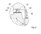
- Fig. 3 shows a further possible embodiment of the invention.
- the following description focuses on differences to the embodiment of Figs. 1 and 2 , and the reader is referred to the description of Figs. 1 and 2 or features which are similar or identical.
- the same or similar reference numbers are employed for features having identical or very similar features.
- the radially outermost surface of the backing ring 18 of the railway axlebox assembly according to Fig. 2 is directly coated with an anti-friction coating 26 without there being an anti-friction sleeve 24 provided as in Fig. 1 .
- the radially outer surface is machined prior to applying the coating 26.
- any suitable coating including coatings with dry-lubricants, nitrocarburation, tungsten carbide, diamond-like carbon, black oxide or tungsten disulfide may be used.
- the surface of the sleeve 24 in the embodiment of Fig. 1 on a radially outer surface of the backing ring 18 may be hardened so as to ensure a sufficiently long service life.
- the sealing arrangement according to the invention ensures reliable protection of the bearing against grease leakage and no supplementary protection on bearing is necessary.
- supplementary protection e.g. by a labyrinth seal placed axially outside of the V-ring sealing may be provided if deemed necessary.
- the solution of the invention ensures low friction compared to fey rings or felt strip system, whereas compared to a labyrinth system, the sealing tightness is better and there is no risk of collision due to the clearance of the system even when the requirements on the machining precision are reduced in order to reduce costs.
- the bearing according to the invention is particularly suitable for space optimization and weight reduction.
Landscapes
- Engineering & Computer Science (AREA)
- Mechanical Engineering (AREA)
- General Engineering & Computer Science (AREA)
- Rolling Contact Bearings (AREA)
- Sealing Of Bearings (AREA)
- Sealing Using Fluids, Sealing Without Contact, And Removal Of Oil (AREA)
Abstract
Description
- The invention relates to a railway axlebox assembly including a bearing including an inner ring adapted to be mounted on a shaft with axial preload and an outer ring adapted to be mounted in a housing, a backing ring providing axial support of the inner ring on an inner end portion of the shaft, and a sealing provided between the backing ring and the inner end portion of the housing.
- Sealing units provided in bearing assemblies of railway axleboxes have to be designed such that they operate under very harsh conditions including temperature changes in a wide range, humidity and introducing dust or dirt from the outside while at the same time maintaining the sealing function and avoiding leakage of oil or grease out of the room accommodating the rollers of the bearings.
- Hitherto, it was presumed that elastomeric sealings are not suitable for applications requiring high robustness such as railway axlebox sealings and that a friction contact would result in excessive wear in applications where dust may enter the contact surface.
- The prior art therefore relied on felt rings or labyrinth seals.
- Existing sealings include sealings which can be mounted directly on the bearing. However, this solution is available only for cylindrical roller bearings, tapered roller bearings or compact tapered roller bearings, because a special mechanic of the bearing is needed, which is not available for other types of bearings.
- Further, it is known to provide a machined labyrinth-sealing between the backing ring and the housing or rear cover. This labyrinth can be positioned such that the parts engage with each other in an axial or radial direction. In principle, the small gap avoids most of the external intrusions. However, the efficiency of this sealing is directly linked to the size of the clearance inside the labyrinth. However, tolerances and permissible displacement must be considered so that the clearances have to be big enough to safely avoid collisions. The drawback of labyrinth seals besides of the high manufacturing costs is a feature that the labyrinth acts as a pump for the bearing grease which is moved outside the housing.
- The traditional solution for the sealing is based on felt strips used in positions between the housing and the backing ring. This kind of sealing has a random efficiency depending on the wear and the environmental condition including temperature, ice, humidity etc. The purpose of the felt strip is to avoid the dust intrusion. However, in order to be efficient, it has to be protected by a labyrinth ring provided axially outside of the felt strip. The felt strip creates important friction which is reduced over the time, and experience shows that the service life of this component is not sufficient for most modern railway applications.
- The inventions seeks to solve the above problems of the prior art by providing a railway axlebox assembly which is cost-saving while ensuring a sufficiently long service life.
- This object is achieved by a railway axlebox assembly according to claim 1, and advantageous modifications or further embodiments of the inventions can be derived from the dependent claims.
- The invention starts from a railway axlebox assembly including a bearing including an inner ring adapted to be mounted on a shaft with axial preload and an outer ring adapted to be mounted in a housing, a backing ring providing axial support of the inner ring on an inner end portion of the shaft; and a sealing provided between the backing ring and the inner end portion of the housing.
- It is proposed that the sealing includes an elastomeric sealing lip with friction contact on a pertinent sealing surface provided on the backing ring. The inventors have found that the problem of wear of elastomeric sealings can be overcome and that the assumption that elastomeric sealings are not suitable for applications requiring high robustness such as railway axlebox sealings is based on a technical prejudice.
- Further, it is proposed that the sealing surface is a surface of an anti-friction sleeve. The use of an anti-friction sleeve is advantageous, because it reduces wear while avoiding high manufacturing costs as they could be the consequence of high-precision machining of a radially outer surface of the backing ring. Further, the anti-friction sleeve enables a simple replacement once the sleeve is worn out.
- In a preferred embodiment of the invention, the anti-friction sleeve includes a stainless steel sleeve with a wall-thickness of less than 0,5mm, preferably less than 0,3mm, and more than 0,1 mm. Anti-friction sleeves of this type are available under the trade name "Speedi Sleeve".
- Further, it is proposed that the anti-friction sleeve is press-fitted over the backing ring. This facilitates the assembly and leads to a robust fixation.
- As an alternative to the anti-friction ring or in addition to this, it is proposed that the sealing surface is a surface coated with anti-friction coating, wherein the sealing surface may be a radially outer surface of the anti-friction ring in the former case.
- In a preferred embodiment of the invention, the sealing surface is a radially outer surface of the backing ring, in particular the radially outermost surface thereof. Further, it is proposed that the sealing lip is fixed on a radially inner surface of the housing and protrudes radially inward. This configuration facilitates the manufacturing of the sealing lip as compared to other configuration, wherein the sealing lip protrudes radially outward and the sealing surface faces radially inward.
- In a preferred embodiment of the invention, the sealing lip is a V-ring sealing. This ensures a tight sealing with two or more sealing lips arranged in a series while avoiding high costs.
- A further aspect of the invention relates to a railway axlebox including an axlebox assembly as described above.
- The following non-limiting description of embodiments of the invention as well as the appended claims and figures show multiple characterizing features of the invention in specific combinations. The skilled person will easily be able to consider further combinations or sub-combinations of these features in order to adapt the invention as defined in the claims to his specific needs.
-
-
Fig. 1 illustrates a railway axlebox including a railway axlebox assembly according to an embodiment of the invention. -
Fig. 2 is a detail ofFig. 1 . -
Fig. 3 illustrates a railway axlebox assembly according to a second embodiment of the invention. -
Fig. 1 illustrates a railway axlebox including a bearing including an inner ring adapted to be mounted on ashaft 12 with axial preload and anouter ring 14 adapted to be mounted in ahousing 16, abacking ring 18 providing axial support of theinner ring 10 on an inner end portion of theshaft 12, and a sealing 20 provided between thebacking ring 18 and the inner end portion of thehousing 16. - Here and in the following, the expression "axially inner end portion" refers to the end of the shaft facing the pertinent wheel as opposed to the axially outer end portion provided with an
end plate 17. - The bearing is a double-row roller bearing with split inner- and outer ring, wherein only one of the rows is illustrated. The
inner ring 10 is fitted over theshaft 12 and clamped thereon by means of theend plate 17. Theshaft 12 has an inner end portion with a rounded profile continuously connecting an essentially cylindrical main part of theshaft 12 with a radially protrudingshoulder portion 27. - The
backing ring 18 supports theinner ring 10 and is provided with a step on a radially inner surface. The step rests on theshoulder 27 of theshaft 12 and supports the axial load of the bearing generated by the clamping action of the end plate. A sealingsurface 20 of thebacking ring 18 is barrel-shaped and located radially above the step of the inner surface of thebacking ring 18. - The bearing may be provided with an additional, integrated sealing including parts fixed on the inner- and outer ring respectively.
- As illustrated in more detail in
Fig. 2 , the sealing 20 includes twoelastomeric sealing lips pertinent sealing surface 22 provided on thebacking ring 18. The sealingsurface 22 is the radially outer surface of ananti-friction sleeve 24. Theanti-friction sleeve 24 is press-fitted over the radially outermost surface of thebacking ring 18. - The
anti-friction sleeve 24 includes a stainless steel sleeve with a wall-thickness of 0,28mm and the radiallyouter sealing surface 22 thereof is coated withanti-friction coating 26. - The sealing 20 is fixed in a
pertinent groove 32 on a radially inner surface of thehousing 16 and protrudes radially inward. - As shown in
Fig. 2 , the sealing 20 is a V-ring sealing containing an axiallyinner lip 28 and an axiallyouter lip 30, wherein the axiallyinner lip 28 rests on thesealing surface 20 so as to be deflected axially inward and the axiallyouter lip 30 rests on the sealingsurface 20 so as to be deflected axially outward. - As a consequence, the axially
outer lip 30 basically protects the bearing from intrusions of particles from the outside, whereas the axially inner lip basically prevents leakage of grease to the outside. -
Fig. 3 shows a further possible embodiment of the invention. In order to avoid repetitions, the following description focuses on differences to the embodiment ofFigs. 1 and 2 , and the reader is referred to the description ofFigs. 1 and 2 or features which are similar or identical. In order to highlight the common function or concept, the same or similar reference numbers are employed for features having identical or very similar features. - The radially outermost surface of the
backing ring 18 of the railway axlebox assembly according toFig. 2 is directly coated with ananti-friction coating 26 without there being ananti-friction sleeve 24 provided as inFig. 1 . The radially outer surface is machined prior to applying thecoating 26. - As to what concerns the
coating 26 in the embodiments inFigs. 1 and 2 , any suitable coating including coatings with dry-lubricants, nitrocarburation, tungsten carbide, diamond-like carbon, black oxide or tungsten disulfide may be used. Further, the surface of thesleeve 24 in the embodiment ofFig. 1 on a radially outer surface of thebacking ring 18 may be hardened so as to ensure a sufficiently long service life. - The sealing arrangement according to the invention ensures reliable protection of the bearing against grease leakage and no supplementary protection on bearing is necessary. However, supplementary protection e.g. by a labyrinth seal placed axially outside of the V-ring sealing may be provided if deemed necessary.
- The solution of the invention ensures low friction compared to fey rings or felt strip system, whereas compared to a labyrinth system, the sealing tightness is better and there is no risk of collision due to the clearance of the system even when the requirements on the machining precision are reduced in order to reduce costs.
- Since no additional sealing on the bearing is necessary, the costs of the bearing may be further reduced and the selection of the bearings may be extended.
- Last but not least, the bearing according to the invention is particularly suitable for space optimization and weight reduction.
Claims (9)
- Railway axlebox assembly including:a. a bearing including an inner ring (10) adapted to be mounted on a shaft (12) with axial preload and an outer ring (14) adapted to be mounted in a housing (16);b. a backing ring (18) providing axial support of the inner ring (10) on an inner end portion of the shaft (12); andc. a sealing (20) provided between the backing ring (18) and the inner end portion of the housing (16);
characterized in thatd. the sealing (20) includes an elastomeric sealing lip (28, 30) bearing with friction contact on a pertinent sealing surface (22) provided on the backing ring (18). - Railway axlebox assembly according to claim 1,
characterized in that the sealing surface (22) is a surface of an anti-friction sleeve (24). - Railway axlebox assembly according to claim 2,
characterized in that the anti-friction sleeve (24) includes a stainless steel sleeve with a wall-thickness of less than 0,5mm, preferably less than 0,3mm, and more than 0,1mm. - Railway axlebox assembly according to one of the preceding claims, characterized in that the anti-friction sleeve (24) is press-fitted over the backing ring (18).
- Railway axlebox assembly according to one of the preceding claims, characterized in that the sealing surface (22) is a surface coated with anti-friction coating (26).
- Railway axlebox assembly according to one of the preceding claims, characterized in that the sealing lip (28, 30) is fixed on a radially inner surface of the housing (16) and protrudes radially inward.
- Railway axlebox assembly according to one of the preceding claims, characterized in that the sealing surface (22) is a radially outer surface of the backing ring (18).
- Railway axlebox assembly according to one of the preceding claims, characterized in that said sealing lip is a V-ring sealing (20).
- Railway axlebox including an axlebox assembly according to one of the preceding claims.
Priority Applications (3)
| Application Number | Priority Date | Filing Date | Title |
|---|---|---|---|
| EP13306107.7A EP2833011A1 (en) | 2013-07-31 | 2013-07-31 | Railway axlebox assembly and railway axlebox including the same |
| CN201410534389.8A CN104340237A (en) | 2013-07-31 | 2014-07-31 | Railway axlebox assembly and railway axlebox including the same |
| US14/448,179 US9481379B2 (en) | 2013-07-31 | 2014-07-31 | Railway axlebox assembly and railway axlebox including the same |
Applications Claiming Priority (1)
| Application Number | Priority Date | Filing Date | Title |
|---|---|---|---|
| EP13306107.7A EP2833011A1 (en) | 2013-07-31 | 2013-07-31 | Railway axlebox assembly and railway axlebox including the same |
Publications (1)
| Publication Number | Publication Date |
|---|---|
| EP2833011A1 true EP2833011A1 (en) | 2015-02-04 |
Family
ID=48951425
Family Applications (1)
| Application Number | Title | Priority Date | Filing Date |
|---|---|---|---|
| EP13306107.7A Withdrawn EP2833011A1 (en) | 2013-07-31 | 2013-07-31 | Railway axlebox assembly and railway axlebox including the same |
Country Status (3)
| Country | Link |
|---|---|
| US (1) | US9481379B2 (en) |
| EP (1) | EP2833011A1 (en) |
| CN (1) | CN104340237A (en) |
Cited By (1)
| Publication number | Priority date | Publication date | Assignee | Title |
|---|---|---|---|---|
| RU220831U1 (en) * | 2022-12-06 | 2023-10-05 | Общество с ограниченной ответственностью "Оптимум" | Axle box bearing unit |
Families Citing this family (3)
| Publication number | Priority date | Publication date | Assignee | Title |
|---|---|---|---|---|
| EP3199419B1 (en) * | 2016-01-28 | 2018-12-19 | Aktiebolaget SKF | Railway axlebox bearing assembly with mounting surface |
| CN109733434B (en) * | 2019-01-07 | 2020-05-08 | 中车青岛四方机车车辆股份有限公司 | Sealing device for changing gauge wheelset and gauge changing wheelset |
| CN118545105A (en) * | 2024-06-11 | 2024-08-27 | 中车株洲电力机车有限公司 | Primary steel spring bogie with optimized span and railway vehicle |
Citations (5)
| Publication number | Priority date | Publication date | Assignee | Title |
|---|---|---|---|---|
| US2962328A (en) * | 1958-04-23 | 1960-11-29 | Skf Svenska Kullagerfab Ab | Double-row cylindrical roller bearings |
| US7314219B1 (en) * | 2005-01-10 | 2008-01-01 | Torque-Traction Technologies, Llc. | Shaft seal assembly |
| JP2008202729A (en) * | 2007-02-21 | 2008-09-04 | Ntn Corp | Sealing device for rolling bearing and rolling bearing |
| US20120082407A1 (en) * | 2010-10-01 | 2012-04-05 | Amsted Rail Company, Inc. | Railway car bearing seal spacer assembly |
| DE102012001379A1 (en) * | 2012-01-24 | 2012-09-06 | Daimler Ag | Beam axle of motor vehicle, has corrosion-resistant structure that is formed with contact surface on which seal is abutted |
Family Cites Families (18)
| Publication number | Priority date | Publication date | Assignee | Title |
|---|---|---|---|---|
| US2260955A (en) * | 1941-03-28 | 1941-10-28 | Timken Roller Bearing Co | Axle-box and other bearing mountings |
| US2600434A (en) * | 1950-06-06 | 1952-06-17 | Saywell Associates | Sealing device |
| US2660490A (en) * | 1951-03-05 | 1953-11-24 | Timken Roller Bearing Co | Railway car axle journal bearing mounting |
| US2712480A (en) * | 1953-01-12 | 1955-07-05 | Skf Ind Inc | Axle boxes |
| GB760304A (en) * | 1954-12-20 | 1956-10-31 | British Timken Ltd | Improvements relating to axle-boxes |
| US2802705A (en) * | 1954-12-29 | 1957-08-13 | Federal Mogul Bower Bearings | Roller bearing journal box |
| US2977138A (en) * | 1957-04-12 | 1961-03-28 | Gen Motors Corp | Flexible seal |
| US2891827A (en) * | 1957-04-12 | 1959-06-23 | Gen Motors Corp | Flexible seal |
| GB864061A (en) * | 1958-08-29 | 1961-03-29 | Timken Roller Bearing Co | Improvements relating to axle-boxes and other bearing housings |
| US3038766A (en) * | 1958-10-15 | 1962-06-12 | Gen Motors Corp | Journal box |
| GB1106584A (en) * | 1966-02-28 | 1968-03-20 | Timken Roller Bearing Co | A bearing sealing case for a removable axle journal seal assembly |
| GB1197196A (en) * | 1966-12-15 | 1970-07-01 | Schaeffler Ohg Industriewerk | A Shaft and Roller Bearing Assembly |
| DE3602051A1 (en) * | 1986-01-24 | 1987-07-30 | Schaeffler Waelzlager Kg | ROLLER BEARING TURN JOINT |
| US5242229A (en) * | 1992-11-25 | 1993-09-07 | The Torrington Company | Sealing structure for standardized bearing ring |
| US6126321A (en) * | 1999-07-16 | 2000-10-03 | Brenco Incorporated | Shaft journal bearing and seal wear ring assembly |
| JP4997532B2 (en) * | 2004-12-16 | 2012-08-08 | 内山工業株式会社 | Rotating member seal structure |
| US20100322544A1 (en) * | 2009-06-22 | 2010-12-23 | Amsted Rail Company, Inc. | Bearing assembly having a dust seal arrangement with contacting and non-contacting dust seals |
| US8596872B2 (en) * | 2009-10-13 | 2013-12-03 | Amsted Rail Company, Inc. | Roller bearing seal |
-
2013
- 2013-07-31 EP EP13306107.7A patent/EP2833011A1/en not_active Withdrawn
-
2014
- 2014-07-31 CN CN201410534389.8A patent/CN104340237A/en active Pending
- 2014-07-31 US US14/448,179 patent/US9481379B2/en not_active Expired - Fee Related
Patent Citations (5)
| Publication number | Priority date | Publication date | Assignee | Title |
|---|---|---|---|---|
| US2962328A (en) * | 1958-04-23 | 1960-11-29 | Skf Svenska Kullagerfab Ab | Double-row cylindrical roller bearings |
| US7314219B1 (en) * | 2005-01-10 | 2008-01-01 | Torque-Traction Technologies, Llc. | Shaft seal assembly |
| JP2008202729A (en) * | 2007-02-21 | 2008-09-04 | Ntn Corp | Sealing device for rolling bearing and rolling bearing |
| US20120082407A1 (en) * | 2010-10-01 | 2012-04-05 | Amsted Rail Company, Inc. | Railway car bearing seal spacer assembly |
| DE102012001379A1 (en) * | 2012-01-24 | 2012-09-06 | Daimler Ag | Beam axle of motor vehicle, has corrosion-resistant structure that is formed with contact surface on which seal is abutted |
Cited By (1)
| Publication number | Priority date | Publication date | Assignee | Title |
|---|---|---|---|---|
| RU220831U1 (en) * | 2022-12-06 | 2023-10-05 | Общество с ограниченной ответственностью "Оптимум" | Axle box bearing unit |
Also Published As
| Publication number | Publication date |
|---|---|
| US20150036954A1 (en) | 2015-02-05 |
| CN104340237A (en) | 2015-02-11 |
| US9481379B2 (en) | 2016-11-01 |
Similar Documents
| Publication | Publication Date | Title |
|---|---|---|
| EP2246581B1 (en) | Roller bearing with sealing device | |
| EP3048340B1 (en) | Sealing arrangement | |
| US8646985B2 (en) | Sealed spherical roller bearing assembly | |
| US20160108966A1 (en) | Rolling-element bearing | |
| US20140301685A1 (en) | Bearing device for axle of railway vehicle | |
| CA2712851C (en) | Roller bearing seal | |
| EP2857704B1 (en) | Cartridge seal with annular lips forming a labyrinth packing, in particular for rolling bearings | |
| US20150176654A1 (en) | Rolling-element bearing including seal unit | |
| US10208802B2 (en) | Sealing device | |
| US10024360B2 (en) | Axial bearing and retainer | |
| US9481379B2 (en) | Railway axlebox assembly and railway axlebox including the same | |
| CN106499734B (en) | Sealing device for roller bearing unit | |
| EP2949972B1 (en) | Cassette seal | |
| CN102345672A (en) | Railway car bearing seal | |
| US9279456B2 (en) | Housing mounted external bearing shield | |
| JP2015161405A (en) | Rolling bearing with sealing device | |
| US10024364B2 (en) | Integrated plastic shield bearing assembly | |
| US20190055988A1 (en) | Bearing cage with lubrication channel | |
| WO2015043629A1 (en) | Rolling bearing with pre-stressing member | |
| JP2017040337A (en) | Rolling bearing | |
| US3029082A (en) | Seal assembly | |
| CN105822662A (en) | Cylindrical roller bearing | |
| EP3009697A1 (en) | Rolling bearing assembly and rotary machine comprising such a rolling bearing assembly | |
| JP2004108372A (en) | Water pump device | |
| US20160319871A1 (en) | Bearing assembly with formed raceways |
Legal Events
| Date | Code | Title | Description |
|---|---|---|---|
| 17P | Request for examination filed |
Effective date: 20130731 |
|
| AK | Designated contracting states |
Kind code of ref document: A1 Designated state(s): AL AT BE BG CH CY CZ DE DK EE ES FI FR GB GR HR HU IE IS IT LI LT LU LV MC MK MT NL NO PL PT RO RS SE SI SK SM TR |
|
| AX | Request for extension of the european patent |
Extension state: BA ME |
|
| PUAI | Public reference made under article 153(3) epc to a published international application that has entered the european phase |
Free format text: ORIGINAL CODE: 0009012 |
|
| RIN1 | Information on inventor provided before grant (corrected) |
Inventor name: PAULIN, LAURENT |
|
| RIN1 | Information on inventor provided before grant (corrected) |
Inventor name: TURMEAU, ARNAUD Inventor name: PAULIN, LAURENT |
|
| R17P | Request for examination filed (corrected) |
Effective date: 20150706 |
|
| RBV | Designated contracting states (corrected) |
Designated state(s): AL AT BE BG CH CY CZ DE DK EE ES FI FR GB GR HR HU IE IS IT LI LT LU LV MC MK MT NL NO PL PT RO RS SE SI SK SM TR |
|
| RIN1 | Information on inventor provided before grant (corrected) |
Inventor name: TURMEAU, ARNAUD Inventor name: PAULIN, LAURENT |
|
| STAA | Information on the status of an ep patent application or granted ep patent |
Free format text: STATUS: EXAMINATION IS IN PROGRESS |
|
| 17Q | First examination report despatched |
Effective date: 20200728 |
|
| GRAP | Despatch of communication of intention to grant a patent |
Free format text: ORIGINAL CODE: EPIDOSNIGR1 |
|
| STAA | Information on the status of an ep patent application or granted ep patent |
Free format text: STATUS: GRANT OF PATENT IS INTENDED |
|
| INTG | Intention to grant announced |
Effective date: 20210120 |
|
| RIN1 | Information on inventor provided before grant (corrected) |
Inventor name: TURMEAU, ARNAUD Inventor name: PAULIN, LAURENT |
|
| STAA | Information on the status of an ep patent application or granted ep patent |
Free format text: STATUS: THE APPLICATION IS DEEMED TO BE WITHDRAWN |
|
| 18D | Application deemed to be withdrawn |
Effective date: 20210601 |