EP2832947A1 - Slider element, assembly method for a guiding device and guiding device - Google Patents
Slider element, assembly method for a guiding device and guiding device Download PDFInfo
- Publication number
- EP2832947A1 EP2832947A1 EP13003860.7A EP13003860A EP2832947A1 EP 2832947 A1 EP2832947 A1 EP 2832947A1 EP 13003860 A EP13003860 A EP 13003860A EP 2832947 A1 EP2832947 A1 EP 2832947A1
- Authority
- EP
- European Patent Office
- Prior art keywords
- snap fit
- slider element
- bearing area
- guiding arm
- guiding
- Prior art date
- Legal status (The legal status is an assumption and is not a legal conclusion. Google has not performed a legal analysis and makes no representation as to the accuracy of the status listed.)
- Granted
Links
Images


Classifications
-
- E—FIXED CONSTRUCTIONS
- E05—LOCKS; KEYS; WINDOW OR DOOR FITTINGS; SAFES
- E05F—DEVICES FOR MOVING WINGS INTO OPEN OR CLOSED POSITION; CHECKS FOR WINGS; WING FITTINGS NOT OTHERWISE PROVIDED FOR, CONCERNED WITH THE FUNCTIONING OF THE WING
- E05F3/00—Closers or openers with braking devices, e.g. checks; Construction of pneumatic or liquid braking devices
- E05F3/22—Additional arrangements for closers, e.g. for holding the wing in opened or other position
-
- E—FIXED CONSTRUCTIONS
- E05—LOCKS; KEYS; WINDOW OR DOOR FITTINGS; SAFES
- E05D—HINGES OR SUSPENSION DEVICES FOR DOORS, WINDOWS OR WINGS
- E05D7/00—Hinges or pivots of special construction
- E05D7/10—Hinges or pivots of special construction to allow easy separation or connection of the parts at the hinge axis
- E05D7/1044—Hinges or pivots of special construction to allow easy separation or connection of the parts at the hinge axis in an axial direction
- E05D7/1055—Hinges or pivots of special construction to allow easy separation or connection of the parts at the hinge axis in an axial direction with snap-fitted pins
-
- E—FIXED CONSTRUCTIONS
- E05—LOCKS; KEYS; WINDOW OR DOOR FITTINGS; SAFES
- E05D—HINGES OR SUSPENSION DEVICES FOR DOORS, WINDOWS OR WINGS
- E05D5/00—Construction of single parts, e.g. the parts for attachment
- E05D5/10—Pins, sockets or sleeves; Removable pins
- E05D5/12—Securing pins in sockets, movably or not
- E05D5/125—Non-removable, snap-fitted pins
-
- E—FIXED CONSTRUCTIONS
- E05—LOCKS; KEYS; WINDOW OR DOOR FITTINGS; SAFES
- E05Y—INDEXING SCHEME ASSOCIATED WITH SUBCLASSES E05D AND E05F, RELATING TO CONSTRUCTION ELEMENTS, ELECTRIC CONTROL, POWER SUPPLY, POWER SIGNAL OR TRANSMISSION, USER INTERFACES, MOUNTING OR COUPLING, DETAILS, ACCESSORIES, AUXILIARY OPERATIONS NOT OTHERWISE PROVIDED FOR, APPLICATION THEREOF
- E05Y2201/00—Constructional elements; Accessories therefor
- E05Y2201/60—Suspension or transmission members; Accessories therefor
- E05Y2201/622—Suspension or transmission members elements
- E05Y2201/708—Sliders
-
- E—FIXED CONSTRUCTIONS
- E05—LOCKS; KEYS; WINDOW OR DOOR FITTINGS; SAFES
- E05Y—INDEXING SCHEME ASSOCIATED WITH SUBCLASSES E05D AND E05F, RELATING TO CONSTRUCTION ELEMENTS, ELECTRIC CONTROL, POWER SUPPLY, POWER SIGNAL OR TRANSMISSION, USER INTERFACES, MOUNTING OR COUPLING, DETAILS, ACCESSORIES, AUXILIARY OPERATIONS NOT OTHERWISE PROVIDED FOR, APPLICATION THEREOF
- E05Y2600/00—Mounting or coupling arrangements for elements provided for in this subclass
- E05Y2600/50—Mounting methods; Positioning
- E05Y2600/52—Toolless
- E05Y2600/53—Snapping
-
- E—FIXED CONSTRUCTIONS
- E05—LOCKS; KEYS; WINDOW OR DOOR FITTINGS; SAFES
- E05Y—INDEXING SCHEME ASSOCIATED WITH SUBCLASSES E05D AND E05F, RELATING TO CONSTRUCTION ELEMENTS, ELECTRIC CONTROL, POWER SUPPLY, POWER SIGNAL OR TRANSMISSION, USER INTERFACES, MOUNTING OR COUPLING, DETAILS, ACCESSORIES, AUXILIARY OPERATIONS NOT OTHERWISE PROVIDED FOR, APPLICATION THEREOF
- E05Y2900/00—Application of doors, windows, wings or fittings thereof
- E05Y2900/10—Application of doors, windows, wings or fittings thereof for buildings or parts thereof
- E05Y2900/13—Type of wing
- E05Y2900/132—Doors
Definitions
- the present invention is related to a slider element for a sliding channel of a guiding device, an assembly method for a guiding device of a door closer as well as a guiding device for a door closer.
- doors comprise so called door closers. These are used after opening of the door to automatically close the door in a further step.
- These door closers usually comprise a guiding arm as well as a guiding or sliding channel.
- a slider element which is configured to be placed within the sliding channel, comprises a bearing area for rotational bearing of the guiding arm of the guiding device. Therefore, the closing movement of the door can be guided by respective rotational movement of the guiding arm relatively to the slider element in a sliding movement of the slider element within the sliding channel.
- One disadvantage of commonly known slider elements is the complexity of mounting the slider element.
- Known assembly methods for the guiding device comprise the step of inserting the slider element into the sliding channel and in a second step mounting the guiding arm at a bearing area of the slider element.
- This mounting step is carried out by the use of fixing elements, for example in the form of screws. Therefore, the mounting of the guiding arm at the slider element takes the respective time for fixing the screw at the respective position.
- Typical materials for the slider elements are plastic materials. To comprise an internal thread in the plastic material is of disadvantage due to the fact that the plastic material sometimes does not give the necessary stiffness for such internal thread. Therefore, the risk occurs that a fixing element in form of a screw is detached by a demounting force by destroying the respective internal thread of the slider element.
- An inventive slider element is in use for a sliding channel of a guiding device of a door closer.
- the slider element comprises at least two sliding surfaces to contact respective channel surfaces of the sliding channel.
- the slider element comprises one bearing area for rotational bearing of a guiding arm of the guiding device.
- the inventive slider element is characterized in that the bearing area comprises at least one snap fit section for snap fit assembly with the guiding arm.
- the assembly method of the slider element and the guiding arm can now take place by a snap fit movement.
- the assembly method with a snap fit is carried out a lot faster and safer. It does not relate to a predefined and necessary mounting force for the fixing element but is only in need for carrying out a snap fit movement. Therefore, the rotational bearing of the guiding arm at the bearing area is received in a more safe manner.
- the use of a snap fit section to enable the snap fit assembly with the guiding arm allows the production of the slider element in an easier and cost efficient manner.
- the slider element can be produced within an injection molding process for example with a plastic material or thermoplastic material. This leads to an easy and cost efficient way of production of the slider element.
- the slider element is formed by one single body, forming all different kinds of functional areas.
- the sliding surfaces as well as the bearing area Therefore, the whole slider element is in particular produced in one single body out of one single material.
- the bearing area is located spaced apart from the sliding surfaces.
- the two sliding surfaces are arranged parallel to each other, while the at least one snap fit section comprises a snap fit axis which is also configured to be parallel to the sliding surfaces.
- an inventive slider can further be characterized in that the snap fit section comprises at least one elastic part section elastically deformable during assembly with the guiding arm.
- the elastic part section can take its elastic functionality from the material of the slider element.
- the geometrical dimension of the snap fit section comprises the elastic part section such that the material parameters of the snap fit section allow the elastic deformability of the elastic part section.
- a slider element which is produced in an integral uniform body can comprise such elastic part section.
- one integral uniform body leads to a further reduced cost of the production of the slider element.
- the bearing area is deformed in an elastic way by deforming elastically the elastic part section.
- the elastic forces within the elastic part section form the snap fit section back into the original position such that the snap fit process is finalized.
- an inventive slider element is characterized in that it comprises a body which integrally forms at least one of the sliding surfaces and the bearing area.
- a uniform body can be produced in an easy and cost efficient way.
- it can be produced during an injection molding process and can be made of plastic, in particular thermoplastic material. Therefore, the slider element is further configured with a reduced complexity. All different functional sections of the slider element are part of one single and uniform body. This leads further to cost efficiency of the slider element.
- an inventive slider element is characterized in that the bearing area comprises at least two snap fit sections whereas the snap fit sections are separated from each other at least partly by a gap.
- Comprising at least two snap fit sections gives the possibility to reduce the elastic deformability of each of the snap fit sections and in the same way providing enough elastic deformability for the assembly movement of the guiding arm.
- the use of a gap is a very easy and cost efficient way to separate each of the snap fit sections from each other.
- the gap comprises geometric dimensions, which are greater or at least equal to the necessary elastic movement of the top end of the snap fit sections. Therefore, it is possible that the snap fit sections can deform inwardly during the snap fit assembly step.
- the respective snap fit sections can snap back in an elastic way and therefore finalize the snap fit movement.
- the gap gives enough space to allow this snap fit deflection of each of the snap fit sections.
- the gap is a full gap which extends between the top end of the bearing area until the most bottom end of the snap fit section.
- an inventive slider element is characterized in that the bearing area is formed in a rotational symmetric way. Due to the fact that the bearing area is made for a rotation bearing of the guiding arm, the rotational symmetric way of a bearing area is directed to that rotational movement of the guiding arm. Therefore, the rotational movement of the guiding arm can take place directly at the bearing area. Therefore, the bearing area can be used for direct or indirect contact to the guiding arm. A further element between the guiding arm and the bearing area can be avoided by the rotational symmetric construction of the bearing area.
- the bearing area is configured to comprise at least in general a cylindrical geometrical dimension.
- an inventive slider element is characterized in that all snap fit sections are formed identical or almost identical. That leads to almost identical snap fit movements for all snap fit sections.
- each snap fit section therefore comprises almost identical snap fit deflections and therefore almost identical elastic deformations.
- this comprises an easy way of manufacturing all the snap fit sections and thereby comprises a cost efficient production possibility.
- an inventive slider element is characterized in that the bearing area comprises a bearing element which is detachable from the body of the slider element and comprises the at least one snap fit section.
- the bearing element is detachable for example by a separate fixing element which comprises the at least one snap fit section.
- this fixing element in form of a bearing element is not a screw for a screw contact or screw assembly but is part of the snap fit assembly which has been discussed in detail above.
- the bearing element is for example configured to be a cap or something like a cap to be placed on top of the bearing area and therefore fixing the guiding arm in the snap fit position. This can in particular be carried out in combination with a bushing which comprises rotational bearing of the guiding arm relatively to the bearing area.
- an inventive slider element is characterized in that at the bearing area at least one sealing element is provided for sealing the contact between the guiding arm and the slider element.
- the sealing element is in particular used by the use of fluids for example hydraulic oils. If there is a lubricant used for example in the guiding channels, the sealing element avoids this lubricant for introduction into the gap between the snap fit sections respectively the bearing area and the guiding arm.
- the at least one snap fit section comprises at least one assembly interface for elastic deformation of the snap fit section.
- This assembly interface can be used as an interface for a mounting tool. Therefore it is more easy to elastically deform the snap fit section and therefore to carry out the assembly as well as the disassembly process.
- the assembly interface can comprise recess sections for introducing parts of a mounting tool.
- a further object of the present invention is to provide an assembly method for a guiding device of a door closer.
- Such an inventive assembly method comprises the following steps:
- an inventive assembly method comprises the same advantages which have been discussed in detail with respect to an inventive slider element.
- a further object of the present invention is a guiding device for a door closer, comprising a sliding channel, a slider element and a guiding arm.
- the inventive guiding device is characterized in that the slider element comprises the features according to the present invention. Therefore, the inventive guiding device comes with the same advantages which have been discussed in detail with respect to the inventive slider element.
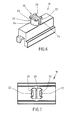
- Figs. 1 and 2 show an inventive guiding device 100 of a door closer. It comprises a sliding channel 110 and a guiding arm 120. Within the sliding channel 110 a slider element 10 is located. The slider element 10 comprises two sliding surfaces 12, which slide along channel surfaces 112 of the sliding channel 110. Moreover, it can be seen that the slider element 10 comprises a bearing area 20, which is used for rotational bearing of the guiding arm 120. During movement inside of the sliding channel 110, the guiding arm 120 can be moved in a rotational manner around the bearing area 20.
- Fig. 3 one embodiment of an inventive slider element 10 is shown.
- the bearing area 20 At the top end of the uniform body 30 of the slider element 10 the bearing area 20 is located. It comprises two snap fit sections 22 which are configured to have the geometrical dimensions in a cylindrical manner. The central axis of these snap fit sections 22 is arranged almost parallel to the sliding surfaces 12.
- the two snap fit sections 22 comprise each one elastic part section 24, which are able for elastic deformation of the whole snap fit section 22 inwardly. Both snap fit sections 22 are separated fully by a gap 26.
- the guiding arm 120 is placed on top of the two snap fit sections 22.
- the two snap fit sections 22 move inwardly, thereby giving way for the guiding arm 120.
- the two snap fit sections 22 can snap back into their original position and thereby finalizing the snap fit fixation. This can in particular also be understood in comparison to Fig. 5 which shows the slider element 10 in a side cross sectional view.
- Fig. 4 shows a further embodiment of an inventive slider element 10.
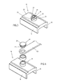
- the bearing area 20 comprises a separate bearing element 28 comprising the snap fit section 22.
- a bushing can be seen, which is placed over the cylindrical bearing area 20.
- the guiding arm 120 is placed around the bushing.
- the cap formed bearing element 28 is placed on top of the guiding arm 120, thereby getting the snap fit section 22 into internal contact with the bearing area 20. Thereby, the snap fit process is finalized.
- Figs. 6 and 7 show a further embodiment of an inventive slider element 10.
- this embodiment comprises a recess for every snap fit section 22 which is configured to form an assembly interface 23.
- the assembly process as well as the disassembly process can be handled faster, easier and in a more convenient way.
Landscapes
- Engineering & Computer Science (AREA)
- Mechanical Engineering (AREA)
- Slide Fasteners (AREA)
- Bearings For Parts Moving Linearly (AREA)
Abstract
Description
- The present invention is related to a slider element for a sliding channel of a guiding device, an assembly method for a guiding device of a door closer as well as a guiding device for a door closer.
- It is already known that doors comprise so called door closers. These are used after opening of the door to automatically close the door in a further step. These door closers usually comprise a guiding arm as well as a guiding or sliding channel. A slider element, which is configured to be placed within the sliding channel, comprises a bearing area for rotational bearing of the guiding arm of the guiding device. Therefore, the closing movement of the door can be guided by respective rotational movement of the guiding arm relatively to the slider element in a sliding movement of the slider element within the sliding channel.
- One disadvantage of commonly known slider elements is the complexity of mounting the slider element. Known assembly methods for the guiding device comprise the step of inserting the slider element into the sliding channel and in a second step mounting the guiding arm at a bearing area of the slider element. This mounting step is carried out by the use of fixing elements, for example in the form of screws. Therefore, the mounting of the guiding arm at the slider element takes the respective time for fixing the screw at the respective position. Moreover, it is a disadvantage to provide the respective internal thread at the slider element to be configured to correspond to the external thread of the screw. Typical materials for the slider elements are plastic materials. To comprise an internal thread in the plastic material is of disadvantage due to the fact that the plastic material sometimes does not give the necessary stiffness for such internal thread. Therefore, the risk occurs that a fixing element in form of a screw is detached by a demounting force by destroying the respective internal thread of the slider element.
- It is an object of the present invention to solve the problems of commonly known slider elements, guiding devices and respective assembly methods. In particular, it is an object of the present invention to reduce the costs of the assembly of the slider element and the guiding device, in particular within an easy manner.
- Aforesaid problem is solved by a slider element with the features of independent claim 1, an assembly method with the features of
independent claim 10 and by a guiding device with the features of independent claim 11. Further features and details of the invention result from the sub claims, the description and the drawings. Features and details, discussed in relation to the inventive slider element, are also related to the inventive assembly method as well as the inventive guiding device and the other way around such that it can be related to the disclosure of each singular invention aspect. - An inventive slider element is in use for a sliding channel of a guiding device of a door closer. The slider element comprises at least two sliding surfaces to contact respective channel surfaces of the sliding channel. Further, the slider element comprises one bearing area for rotational bearing of a guiding arm of the guiding device. The inventive slider element is characterized in that the bearing area comprises at least one snap fit section for snap fit assembly with the guiding arm.
- In contrast to commonly known slider elements, the assembly method of the slider element and the guiding arm can now take place by a snap fit movement. Compared to the use of fixing elements in form of a screw, the assembly method with a snap fit is carried out a lot faster and safer. It does not relate to a predefined and necessary mounting force for the fixing element but is only in need for carrying out a snap fit movement. Therefore, the rotational bearing of the guiding arm at the bearing area is received in a more safe manner.
- Moreover, the use of a snap fit section to enable the snap fit assembly with the guiding arm allows the production of the slider element in an easier and cost efficient manner. In particular, the slider element can be produced within an injection molding process for example with a plastic material or thermoplastic material. This leads to an easy and cost efficient way of production of the slider element.
- In particular, the slider element is formed by one single body, forming all different kinds of functional areas. In particular, the sliding surfaces as well as the bearing area. Therefore, the whole slider element is in particular produced in one single body out of one single material.
- The bearing area is located spaced apart from the sliding surfaces. In particular, the two sliding surfaces are arranged parallel to each other, while the at least one snap fit section comprises a snap fit axis which is also configured to be parallel to the sliding surfaces.
- An inventive slider can further be characterized in that the snap fit section comprises at least one elastic part section elastically deformable during assembly with the guiding arm. This leads to a more easy production step of the at least one snap fit section. The elastic part section can take its elastic functionality from the material of the slider element. For example, the geometrical dimension of the snap fit section comprises the elastic part section such that the material parameters of the snap fit section allow the elastic deformability of the elastic part section. In particular, a slider element which is produced in an integral uniform body can comprise such elastic part section. Moreover, one integral uniform body leads to a further reduced cost of the production of the slider element. During the assembly process, the guiding arm is placed over the bearing area. During the movement into the snap fit position of the guiding arm, the bearing area is deformed in an elastic way by deforming elastically the elastic part section. After the guiding arm has arrived at the snap fit position, the elastic forces within the elastic part section form the snap fit section back into the original position such that the snap fit process is finalized.
- It is further of advantage, if an inventive slider element is characterized in that it comprises a body which integrally forms at least one of the sliding surfaces and the bearing area. As it has already been discussed in detail, such a uniform body can be produced in an easy and cost efficient way. In particular, it can be produced during an injection molding process and can be made of plastic, in particular thermoplastic material. Therefore, the slider element is further configured with a reduced complexity. All different functional sections of the slider element are part of one single and uniform body. This leads further to cost efficiency of the slider element.
- It is further of advantage, if an inventive slider element is characterized in that the bearing area comprises at least two snap fit sections whereas the snap fit sections are separated from each other at least partly by a gap. Comprising at least two snap fit sections gives the possibility to reduce the elastic deformability of each of the snap fit sections and in the same way providing enough elastic deformability for the assembly movement of the guiding arm. The use of a gap is a very easy and cost efficient way to separate each of the snap fit sections from each other. In particular, the gap comprises geometric dimensions, which are greater or at least equal to the necessary elastic movement of the top end of the snap fit sections. Therefore, it is possible that the snap fit sections can deform inwardly during the snap fit assembly step. After the guiding arm has arrived at its snap position, the respective snap fit sections can snap back in an elastic way and therefore finalize the snap fit movement. During the snap fit movement, the gap gives enough space to allow this snap fit deflection of each of the snap fit sections. In particular, the gap is a full gap which extends between the top end of the bearing area until the most bottom end of the snap fit section.
- It is further of advantage, if an inventive slider element is characterized in that the bearing area is formed in a rotational symmetric way. Due to the fact that the bearing area is made for a rotation bearing of the guiding arm, the rotational symmetric way of a bearing area is directed to that rotational movement of the guiding arm. Therefore, the rotational movement of the guiding arm can take place directly at the bearing area. Therefore, the bearing area can be used for direct or indirect contact to the guiding arm. A further element between the guiding arm and the bearing area can be avoided by the rotational symmetric construction of the bearing area. For example, the bearing area is configured to comprise at least in general a cylindrical geometrical dimension.
- It is further possible that an inventive slider element is characterized in that all snap fit sections are formed identical or almost identical. That leads to almost identical snap fit movements for all snap fit sections. During the assembly of the guiding arm each snap fit section therefore comprises almost identical snap fit deflections and therefore almost identical elastic deformations. This leads to in general symmetrical snap fit movement of the guiding arm. Unwilling tilting of the guiding arm during the assembly step is avoided by such a geometrical expression of each of the snap fit sections. Moreover, this comprises an easy way of manufacturing all the snap fit sections and thereby comprises a cost efficient production possibility.
- Further it is possible that an inventive slider element is characterized in that the bearing area comprises a bearing element which is detachable from the body of the slider element and comprises the at least one snap fit section. This is a special embodiment of the present invention. The bearing element is detachable for example by a separate fixing element which comprises the at least one snap fit section. In contrast to commonly known slider elements this fixing element in form of a bearing element is not a screw for a screw contact or screw assembly but is part of the snap fit assembly which has been discussed in detail above. After placing the guiding arm in the area of the bearing area, the bearing element can be put on top of the guiding arm and therefore fixes the guiding arm in the snap fit position. The snap fit section can therefore get into snap fit contact with respective contact surfaces of the bearing area. The bearing element is for example configured to be a cap or something like a cap to be placed on top of the bearing area and therefore fixing the guiding arm in the snap fit position. This can in particular be carried out in combination with a bushing which comprises rotational bearing of the guiding arm relatively to the bearing area.
- It is further of advantage, if an inventive slider element is characterized in that at the bearing area at least one sealing element is provided for sealing the contact between the guiding arm and the slider element. The sealing element is in particular used by the use of fluids for example hydraulic oils. If there is a lubricant used for example in the guiding channels, the sealing element avoids this lubricant for introduction into the gap between the snap fit sections respectively the bearing area and the guiding arm.
- It is further of advantage, if the at least one snap fit section comprises at least one assembly interface for elastic deformation of the snap fit section. This assembly interface can be used as an interface for a mounting tool. Therefore it is more easy to elastically deform the snap fit section and therefore to carry out the assembly as well as the disassembly process. For example, the assembly interface can comprise recess sections for introducing parts of a mounting tool.
- A further object of the present invention is to provide an assembly method for a guiding device of a door closer. Such an inventive assembly method comprises the following steps:
- Providing a slider element with the features of the present invention,
- Moving a guiding arm over the bearing area by causing elastic deformation of a snap fit section,
- Finalizing the snap fit assembly by moving the guiding arm in its final position causing the snap fit section to snap back in its assembled position.
- Due to the use of an inventive slider element, an inventive assembly method comprises the same advantages which have been discussed in detail with respect to an inventive slider element.
- A further object of the present invention is a guiding device for a door closer, comprising a sliding channel, a slider element and a guiding arm. The inventive guiding device is characterized in that the slider element comprises the features according to the present invention. Therefore, the inventive guiding device comes with the same advantages which have been discussed in detail with respect to the inventive slider element.
- The present invention is discussed in more detail with respect to the accompanying drawings. The figures show in schematic way:
- Fig. 1
- a first embodiment of an inventive slider element,
- Fig. 2
- the embodiment of
Fig. 1 in a birds eye view, - Fig. 3
- a further embodiment of an inventive slider element,
- Fig. 4
- a further embodiment of an inventive slider element in an exploded view,
- Fig. 5
- a further embodiment of an inventive slider element in a schematic cross sectional view,
- Fig. 6
- a further embodiment of an inventive slider element and
- Fig. 7
- the embodiment of
Fig. 6 in a birds eye view. -
Figs. 1 and 2 show aninventive guiding device 100 of a door closer. It comprises a slidingchannel 110 and a guidingarm 120. Within the sliding channel 110 aslider element 10 is located. Theslider element 10 comprises two slidingsurfaces 12, which slide along channel surfaces 112 of the slidingchannel 110. Moreover, it can be seen that theslider element 10 comprises abearing area 20, which is used for rotational bearing of the guidingarm 120. During movement inside of the slidingchannel 110, the guidingarm 120 can be moved in a rotational manner around the bearingarea 20. - In
Fig. 3 , one embodiment of aninventive slider element 10 is shown. At the top end of theuniform body 30 of theslider element 10 thebearing area 20 is located. It comprises two snapfit sections 22 which are configured to have the geometrical dimensions in a cylindrical manner. The central axis of these snapfit sections 22 is arranged almost parallel to the sliding surfaces 12. - The two snap
fit sections 22 comprise each oneelastic part section 24, which are able for elastic deformation of the whole snapfit section 22 inwardly. Both snapfit sections 22 are separated fully by agap 26. - During the mounting assembly steps of guiding
arm 120, the guidingarm 120 is placed on top of the two snapfit sections 22. During the downward movement of the guidingarm 120, the two snapfit sections 22 move inwardly, thereby giving way for the guidingarm 120. When the guidingarm 120 arrives its snap fit position at the lowest end, the two snapfit sections 22 can snap back into their original position and thereby finalizing the snap fit fixation. This can in particular also be understood in comparison toFig. 5 which shows theslider element 10 in a side cross sectional view. -
Fig. 4 shows a further embodiment of aninventive slider element 10. In this particular embodiment, the bearingarea 20 comprises aseparate bearing element 28 comprising the snapfit section 22. Moreover, a bushing can be seen, which is placed over thecylindrical bearing area 20. In a further step, the guidingarm 120 is placed around the bushing. In a finalizing step, the cap formed bearingelement 28 is placed on top of the guidingarm 120, thereby getting the snapfit section 22 into internal contact with the bearingarea 20. Thereby, the snap fit process is finalized. -
Figs. 6 and 7 show a further embodiment of aninventive slider element 10. In particular this embodiment comprises a recess for every snapfit section 22 which is configured to form anassembly interface 23. One can use a mounting tool to interact geometrically with theassembly interface 23 and therefore elastically deform the snapfit section 22. The assembly process as well as the disassembly process can be handled faster, easier and in a more convenient way. - The aforesaid discussion of the figures describes the invention only by the way of examples. Different features of the different embodiments can be combined freely, if of technical sense.
-
- 10
- slider element
- 12
- sliding surface
- 20
- bearing area
- 22
- snap fit section
- 23
- assembly interface
- 24
- elastic part section
- 26
- gap
- 28
- bearing element
- 30
- body
- 100
- guiding device
- 110
- sliding channel
- 112
- channel surface
- 120
- guiding arm
Claims (11)
- Slider element (10) for a sliding channel (110) of a guiding device (100) of a door closer, comprising at least two sliding surfaces (12) to contact respective channel surfaces (112) of the sliding channel (110), further comprising one bearing area (20) for rotational bearing of a guiding arm (120) of the guiding device (100), characterized in that the bearing area (20) comprises at least one snap fit section (22) for snap fit assembly with the guiding arm (120).
- Slider element (10) according to claim 1, characterized in that the snap fit section (22) comprises at least one elastic part section (24) elastically deformable during assembly with the guiding arm (120).
- Slider element (10) according to any of the preceding claims, characterized in that it comprises a body (30) which integrally forms at least one of the sliding surfaces (12) and the bearing area (20).
- Slider element (10) according to any of the preceding claims, characterized in that the bearing area (20) comprises at least two snap fit sections (22) whereas the snap fit sections (22) are separated from each other at least partly by a gap (26).
- Slider element (10) according to any of the preceding claims, characterized in that the bearing area (20) is formed in a rotational symmetric way.
- Slider element (10) according to any of the preceding claims, characterized in that all snap fit sections (22) are formed identical or almost identical.
- Slider element (10) according to any of the preceding claims, characterized in that the bearing area (20) comprises a bearing element (28) which is detachable from the body (30) of the slider element (10) and comprises the at least one snap fit section (22).
- Slider element (10) according to any of the preceding claims, characterized in that at the bearing area (20) at least one sealing element is provided for sealing the contact between the guiding arm (120) and the slider element (10).
- Slider element (10) according to any of the preceding claims, characterized in that the at least one snap fit section (22) comprises at least one assembly interface (23) for elastic deformation of the snap fit section (22).
- Assembly method for a guiding device (100) of a door closer, comprising the following steps:- Providing a slider element (10) with the features of any of claims 1 to 9,- Moving a guiding arm (120) over the bearing area (20) by causing elastic deformation of a snap fit section (22),- Finalizing the snap fit assembly by moving the guiding arm (120) in its final position causing the snap fit section (22) to snap back in its assembled position.
- Guiding device (100) for a door closer, comprising a sliding channel (110), a slider element (10) and a guiding arm (120), characterized in that the slider element (10) comprises the features of any of claims 1 to 9.
Priority Applications (2)
| Application Number | Priority Date | Filing Date | Title |
|---|---|---|---|
| EP13003860.7A EP2832947B1 (en) | 2013-08-02 | 2013-08-02 | Slider element, assembly method for a guiding device and guiding device |
| CN201410379609.4A CN104343306B (en) | 2013-08-02 | 2014-08-04 | Slider component, assembly method and guide device for guide device |
Applications Claiming Priority (1)
| Application Number | Priority Date | Filing Date | Title |
|---|---|---|---|
| EP13003860.7A EP2832947B1 (en) | 2013-08-02 | 2013-08-02 | Slider element, assembly method for a guiding device and guiding device |
Publications (2)
| Publication Number | Publication Date |
|---|---|
| EP2832947A1 true EP2832947A1 (en) | 2015-02-04 |
| EP2832947B1 EP2832947B1 (en) | 2020-04-15 |
Family
ID=48979501
Family Applications (1)
| Application Number | Title | Priority Date | Filing Date |
|---|---|---|---|
| EP13003860.7A Active EP2832947B1 (en) | 2013-08-02 | 2013-08-02 | Slider element, assembly method for a guiding device and guiding device |
Country Status (2)
| Country | Link |
|---|---|
| EP (1) | EP2832947B1 (en) |
| CN (1) | CN104343306B (en) |
Citations (3)
| Publication number | Priority date | Publication date | Assignee | Title |
|---|---|---|---|---|
| DE202005015034U1 (en) * | 2005-09-22 | 2006-01-19 | Siegenia-Aubi Kg | Slider for a fitting |
| DE102005000195A1 (en) * | 2005-12-21 | 2007-06-28 | Siegenia-Aubi Kg | Fitting for window or door, has guide rail and sliding component which is guided in undercut profile groove of guide rail such that it is displaced longitudinally along adjustment axis |
| DE102007021979B3 (en) * | 2007-05-10 | 2008-08-07 | Hautau Gmbh | Sliding device for guiding in guide rail fastened to window frame has elastically flexible locking elements which automatically lock locking plate in locking position and in released position automatically block it against displacement |
Family Cites Families (2)
| Publication number | Priority date | Publication date | Assignee | Title |
|---|---|---|---|---|
| CN2438809Y (en) * | 2000-08-16 | 2001-07-11 | 林新达 | Closer for sliding door |
| DE102011051668A1 (en) * | 2011-07-08 | 2013-01-10 | Dorma Gmbh + Co. Kg | Slider, in particular for a door closer |
-
2013
- 2013-08-02 EP EP13003860.7A patent/EP2832947B1/en active Active
-
2014
- 2014-08-04 CN CN201410379609.4A patent/CN104343306B/en active Active
Patent Citations (3)
| Publication number | Priority date | Publication date | Assignee | Title |
|---|---|---|---|---|
| DE202005015034U1 (en) * | 2005-09-22 | 2006-01-19 | Siegenia-Aubi Kg | Slider for a fitting |
| DE102005000195A1 (en) * | 2005-12-21 | 2007-06-28 | Siegenia-Aubi Kg | Fitting for window or door, has guide rail and sliding component which is guided in undercut profile groove of guide rail such that it is displaced longitudinally along adjustment axis |
| DE102007021979B3 (en) * | 2007-05-10 | 2008-08-07 | Hautau Gmbh | Sliding device for guiding in guide rail fastened to window frame has elastically flexible locking elements which automatically lock locking plate in locking position and in released position automatically block it against displacement |
Also Published As
| Publication number | Publication date |
|---|---|
| CN104343306B (en) | 2018-04-27 |
| CN104343306A (en) | 2015-02-11 |
| EP2832947B1 (en) | 2020-04-15 |
Similar Documents
| Publication | Publication Date | Title |
|---|---|---|
| EP2392224B1 (en) | Cream pot with multiple wall housing | |
| EP1843441A3 (en) | Grommet for a casing opening for a cable | |
| EP3087672B1 (en) | Housing for solar panel electric connection | |
| CN103850561A (en) | Door actuator | |
| US20170328114A1 (en) | Extensible/contractible driving device and openable body opening/closing device | |
| DE112015003121T5 (en) | Sealing mechanism for drive housing | |
| KR200489205Y1 (en) | Interlocking bearing | |
| KR100820020B1 (en) | Ball Screw Linear Motion Guide | |
| KR20140139978A (en) | Captive retaining means for a fastening screw on a component | |
| EP2832947B1 (en) | Slider element, assembly method for a guiding device and guiding device | |
| IT201800003265A1 (en) | Rotary cartridge damper including a linear damper. | |
| EP3442083B1 (en) | Method for producing a contact device, contact device and contact system | |
| JP6900404B2 (en) | Methods for manufacturing sleeves by injection molding and related molding tools, as well as sleeves as deliverables. | |
| CN104755243A (en) | Positioning device for a mold | |
| CN205291477U (en) | Three -dimensional angie type die cavity forms device | |
| CN112413147A (en) | Electronic expansion valve and processing method thereof | |
| WO2008031766A1 (en) | Preform for producing a device for packaging and applying a product | |
| KR102228122B1 (en) | Molding apparatus and method of manufacturing resin modling product | |
| US10549901B2 (en) | Double container | |
| EP3260727B1 (en) | Damper and damper production method | |
| CN206225228U (en) | A kind of triangle off circuit tap changer | |
| CN106449217B (en) | A kind of triangle off circuit tap changer | |
| EP2841793B1 (en) | Damper | |
| EP3106707B1 (en) | Damper device | |
| CN112392974B (en) | Electronic expansion valve |
Legal Events
| Date | Code | Title | Description |
|---|---|---|---|
| 17P | Request for examination filed |
Effective date: 20130802 |
|
| AK | Designated contracting states |
Kind code of ref document: A1 Designated state(s): AL AT BE BG CH CY CZ DE DK EE ES FI FR GB GR HR HU IE IS IT LI LT LU LV MC MK MT NL NO PL PT RO RS SE SI SK SM TR |
|
| AX | Request for extension of the european patent |
Extension state: BA ME |
|
| PUAI | Public reference made under article 153(3) epc to a published international application that has entered the european phase |
Free format text: ORIGINAL CODE: 0009012 |
|
| RAP1 | Party data changed (applicant data changed or rights of an application transferred) |
Owner name: DORMA DEUTSCHLAND GMBH |
|
| R17P | Request for examination filed (corrected) |
Effective date: 20150617 |
|
| RBV | Designated contracting states (corrected) |
Designated state(s): AL AT BE BG CH CY CZ DE DK EE ES FI FR GB GR HR HU IE IS IT LI LT LU LV MC MK MT NL NO PL PT RO RS SE SI SK SM TR |
|
| RAP1 | Party data changed (applicant data changed or rights of an application transferred) |
Owner name: DORMAKABA DEUTSCHLAND GMBH |
|
| STAA | Information on the status of an ep patent application or granted ep patent |
Free format text: STATUS: EXAMINATION IS IN PROGRESS |
|
| 17Q | First examination report despatched |
Effective date: 20180606 |
|
| GRAP | Despatch of communication of intention to grant a patent |
Free format text: ORIGINAL CODE: EPIDOSNIGR1 |
|
| STAA | Information on the status of an ep patent application or granted ep patent |
Free format text: STATUS: GRANT OF PATENT IS INTENDED |
|
| INTG | Intention to grant announced |
Effective date: 20191115 |
|
| GRAS | Grant fee paid |
Free format text: ORIGINAL CODE: EPIDOSNIGR3 |
|
| GRAA | (expected) grant |
Free format text: ORIGINAL CODE: 0009210 |
|
| STAA | Information on the status of an ep patent application or granted ep patent |
Free format text: STATUS: THE PATENT HAS BEEN GRANTED |
|
| AK | Designated contracting states |
Kind code of ref document: B1 Designated state(s): AL AT BE BG CH CY CZ DE DK EE ES FI FR GB GR HR HU IE IS IT LI LT LU LV MC MK MT NL NO PL PT RO RS SE SI SK SM TR |
|
| REG | Reference to a national code |
Ref country code: GB Ref legal event code: FG4D Ref country code: CH Ref legal event code: EP |
|
| REG | Reference to a national code |
Ref country code: DE Ref legal event code: R096 Ref document number: 602013067853 Country of ref document: DE |
|
| REG | Reference to a national code |
Ref country code: IE Ref legal event code: FG4D |
|
| REG | Reference to a national code |
Ref country code: AT Ref legal event code: REF Ref document number: 1257480 Country of ref document: AT Kind code of ref document: T Effective date: 20200515 |
|
| REG | Reference to a national code |
Ref country code: NL Ref legal event code: FP |
|
| REG | Reference to a national code |
Ref country code: LT Ref legal event code: MG4D |
|
| PG25 | Lapsed in a contracting state [announced via postgrant information from national office to epo] |
Ref country code: IS Free format text: LAPSE BECAUSE OF FAILURE TO SUBMIT A TRANSLATION OF THE DESCRIPTION OR TO PAY THE FEE WITHIN THE PRESCRIBED TIME-LIMIT Effective date: 20200815 Ref country code: SE Free format text: LAPSE BECAUSE OF FAILURE TO SUBMIT A TRANSLATION OF THE DESCRIPTION OR TO PAY THE FEE WITHIN THE PRESCRIBED TIME-LIMIT Effective date: 20200415 Ref country code: FI Free format text: LAPSE BECAUSE OF FAILURE TO SUBMIT A TRANSLATION OF THE DESCRIPTION OR TO PAY THE FEE WITHIN THE PRESCRIBED TIME-LIMIT Effective date: 20200415 Ref country code: LT Free format text: LAPSE BECAUSE OF FAILURE TO SUBMIT A TRANSLATION OF THE DESCRIPTION OR TO PAY THE FEE WITHIN THE PRESCRIBED TIME-LIMIT Effective date: 20200415 Ref country code: PT Free format text: LAPSE BECAUSE OF FAILURE TO SUBMIT A TRANSLATION OF THE DESCRIPTION OR TO PAY THE FEE WITHIN THE PRESCRIBED TIME-LIMIT Effective date: 20200817 Ref country code: NO Free format text: LAPSE BECAUSE OF FAILURE TO SUBMIT A TRANSLATION OF THE DESCRIPTION OR TO PAY THE FEE WITHIN THE PRESCRIBED TIME-LIMIT Effective date: 20200715 Ref country code: GR Free format text: LAPSE BECAUSE OF FAILURE TO SUBMIT A TRANSLATION OF THE DESCRIPTION OR TO PAY THE FEE WITHIN THE PRESCRIBED TIME-LIMIT Effective date: 20200716 |
|
| REG | Reference to a national code |
Ref country code: AT Ref legal event code: MK05 Ref document number: 1257480 Country of ref document: AT Kind code of ref document: T Effective date: 20200415 |
|
| PG25 | Lapsed in a contracting state [announced via postgrant information from national office to epo] |
Ref country code: BG Free format text: LAPSE BECAUSE OF FAILURE TO SUBMIT A TRANSLATION OF THE DESCRIPTION OR TO PAY THE FEE WITHIN THE PRESCRIBED TIME-LIMIT Effective date: 20200715 Ref country code: HR Free format text: LAPSE BECAUSE OF FAILURE TO SUBMIT A TRANSLATION OF THE DESCRIPTION OR TO PAY THE FEE WITHIN THE PRESCRIBED TIME-LIMIT Effective date: 20200415 Ref country code: LV Free format text: LAPSE BECAUSE OF FAILURE TO SUBMIT A TRANSLATION OF THE DESCRIPTION OR TO PAY THE FEE WITHIN THE PRESCRIBED TIME-LIMIT Effective date: 20200415 Ref country code: RS Free format text: LAPSE BECAUSE OF FAILURE TO SUBMIT A TRANSLATION OF THE DESCRIPTION OR TO PAY THE FEE WITHIN THE PRESCRIBED TIME-LIMIT Effective date: 20200415 |
|
| PG25 | Lapsed in a contracting state [announced via postgrant information from national office to epo] |
Ref country code: AL Free format text: LAPSE BECAUSE OF FAILURE TO SUBMIT A TRANSLATION OF THE DESCRIPTION OR TO PAY THE FEE WITHIN THE PRESCRIBED TIME-LIMIT Effective date: 20200415 |
|
| REG | Reference to a national code |
Ref country code: DE Ref legal event code: R097 Ref document number: 602013067853 Country of ref document: DE |
|
| PG25 | Lapsed in a contracting state [announced via postgrant information from national office to epo] |
Ref country code: EE Free format text: LAPSE BECAUSE OF FAILURE TO SUBMIT A TRANSLATION OF THE DESCRIPTION OR TO PAY THE FEE WITHIN THE PRESCRIBED TIME-LIMIT Effective date: 20200415 Ref country code: RO Free format text: LAPSE BECAUSE OF FAILURE TO SUBMIT A TRANSLATION OF THE DESCRIPTION OR TO PAY THE FEE WITHIN THE PRESCRIBED TIME-LIMIT Effective date: 20200415 Ref country code: AT Free format text: LAPSE BECAUSE OF FAILURE TO SUBMIT A TRANSLATION OF THE DESCRIPTION OR TO PAY THE FEE WITHIN THE PRESCRIBED TIME-LIMIT Effective date: 20200415 Ref country code: CZ Free format text: LAPSE BECAUSE OF FAILURE TO SUBMIT A TRANSLATION OF THE DESCRIPTION OR TO PAY THE FEE WITHIN THE PRESCRIBED TIME-LIMIT Effective date: 20200415 Ref country code: DK Free format text: LAPSE BECAUSE OF FAILURE TO SUBMIT A TRANSLATION OF THE DESCRIPTION OR TO PAY THE FEE WITHIN THE PRESCRIBED TIME-LIMIT Effective date: 20200415 Ref country code: SM Free format text: LAPSE BECAUSE OF FAILURE TO SUBMIT A TRANSLATION OF THE DESCRIPTION OR TO PAY THE FEE WITHIN THE PRESCRIBED TIME-LIMIT Effective date: 20200415 Ref country code: ES Free format text: LAPSE BECAUSE OF FAILURE TO SUBMIT A TRANSLATION OF THE DESCRIPTION OR TO PAY THE FEE WITHIN THE PRESCRIBED TIME-LIMIT Effective date: 20200415 |
|
| PLBE | No opposition filed within time limit |
Free format text: ORIGINAL CODE: 0009261 |
|
| STAA | Information on the status of an ep patent application or granted ep patent |
Free format text: STATUS: NO OPPOSITION FILED WITHIN TIME LIMIT |
|
| PG25 | Lapsed in a contracting state [announced via postgrant information from national office to epo] |
Ref country code: SK Free format text: LAPSE BECAUSE OF FAILURE TO SUBMIT A TRANSLATION OF THE DESCRIPTION OR TO PAY THE FEE WITHIN THE PRESCRIBED TIME-LIMIT Effective date: 20200415 Ref country code: PL Free format text: LAPSE BECAUSE OF FAILURE TO SUBMIT A TRANSLATION OF THE DESCRIPTION OR TO PAY THE FEE WITHIN THE PRESCRIBED TIME-LIMIT Effective date: 20200415 |
|
| 26N | No opposition filed |
Effective date: 20210118 |
|
| PG25 | Lapsed in a contracting state [announced via postgrant information from national office to epo] |
Ref country code: MC Free format text: LAPSE BECAUSE OF FAILURE TO SUBMIT A TRANSLATION OF THE DESCRIPTION OR TO PAY THE FEE WITHIN THE PRESCRIBED TIME-LIMIT Effective date: 20200415 |
|
| REG | Reference to a national code |
Ref country code: CH Ref legal event code: PL |
|
| PG25 | Lapsed in a contracting state [announced via postgrant information from national office to epo] |
Ref country code: LU Free format text: LAPSE BECAUSE OF NON-PAYMENT OF DUE FEES Effective date: 20200802 Ref country code: LI Free format text: LAPSE BECAUSE OF NON-PAYMENT OF DUE FEES Effective date: 20200831 Ref country code: CH Free format text: LAPSE BECAUSE OF NON-PAYMENT OF DUE FEES Effective date: 20200831 |
|
| REG | Reference to a national code |
Ref country code: BE Ref legal event code: MM Effective date: 20200831 |
|
| PG25 | Lapsed in a contracting state [announced via postgrant information from national office to epo] |
Ref country code: SI Free format text: LAPSE BECAUSE OF FAILURE TO SUBMIT A TRANSLATION OF THE DESCRIPTION OR TO PAY THE FEE WITHIN THE PRESCRIBED TIME-LIMIT Effective date: 20200415 |
|
| PG25 | Lapsed in a contracting state [announced via postgrant information from national office to epo] |
Ref country code: IE Free format text: LAPSE BECAUSE OF NON-PAYMENT OF DUE FEES Effective date: 20200802 Ref country code: BE Free format text: LAPSE BECAUSE OF NON-PAYMENT OF DUE FEES Effective date: 20200831 |
|
| PG25 | Lapsed in a contracting state [announced via postgrant information from national office to epo] |
Ref country code: TR Free format text: LAPSE BECAUSE OF FAILURE TO SUBMIT A TRANSLATION OF THE DESCRIPTION OR TO PAY THE FEE WITHIN THE PRESCRIBED TIME-LIMIT Effective date: 20200415 Ref country code: MT Free format text: LAPSE BECAUSE OF FAILURE TO SUBMIT A TRANSLATION OF THE DESCRIPTION OR TO PAY THE FEE WITHIN THE PRESCRIBED TIME-LIMIT Effective date: 20200415 Ref country code: CY Free format text: LAPSE BECAUSE OF FAILURE TO SUBMIT A TRANSLATION OF THE DESCRIPTION OR TO PAY THE FEE WITHIN THE PRESCRIBED TIME-LIMIT Effective date: 20200415 |
|
| PG25 | Lapsed in a contracting state [announced via postgrant information from national office to epo] |
Ref country code: MK Free format text: LAPSE BECAUSE OF FAILURE TO SUBMIT A TRANSLATION OF THE DESCRIPTION OR TO PAY THE FEE WITHIN THE PRESCRIBED TIME-LIMIT Effective date: 20200415 |
|
| PGFP | Annual fee paid to national office [announced via postgrant information from national office to epo] |
Ref country code: NL Payment date: 20250821 Year of fee payment: 13 |
|
| PGFP | Annual fee paid to national office [announced via postgrant information from national office to epo] |
Ref country code: DE Payment date: 20250820 Year of fee payment: 13 |
|
| PGFP | Annual fee paid to national office [announced via postgrant information from national office to epo] |
Ref country code: IT Payment date: 20250825 Year of fee payment: 13 |
|
| PGFP | Annual fee paid to national office [announced via postgrant information from national office to epo] |
Ref country code: GB Payment date: 20250820 Year of fee payment: 13 |
|
| PGFP | Annual fee paid to national office [announced via postgrant information from national office to epo] |
Ref country code: FR Payment date: 20250829 Year of fee payment: 13 |